

Thermal Performance of Slotted Light Steel-Framed Composite Wall


Abstract
:1. Introduction
2. Test Overview
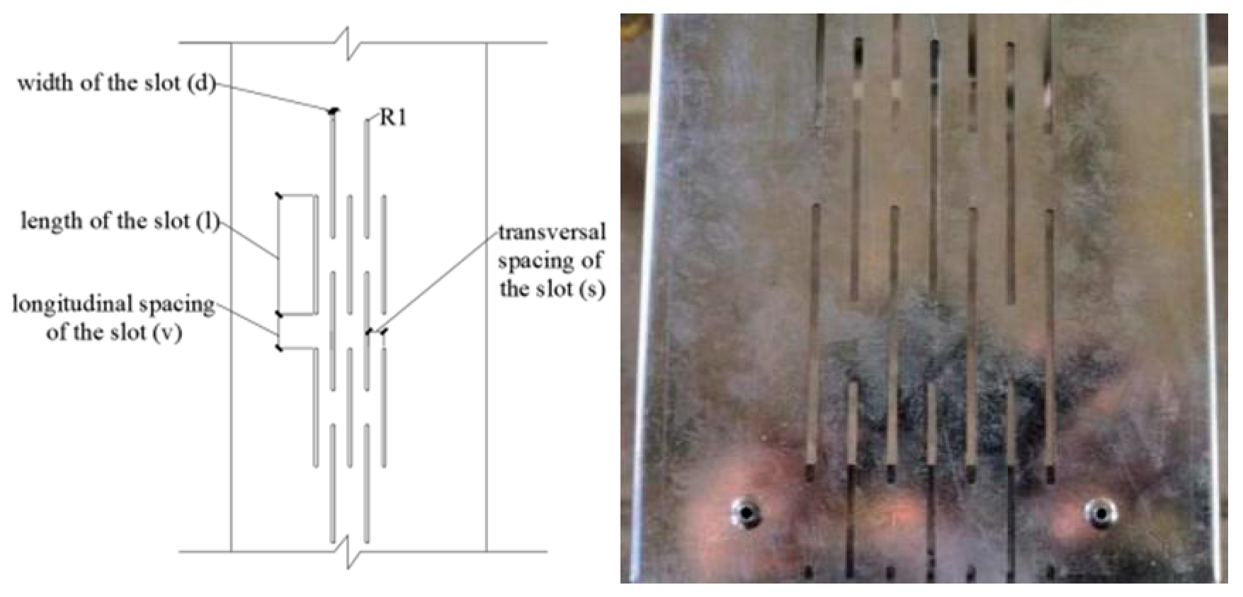
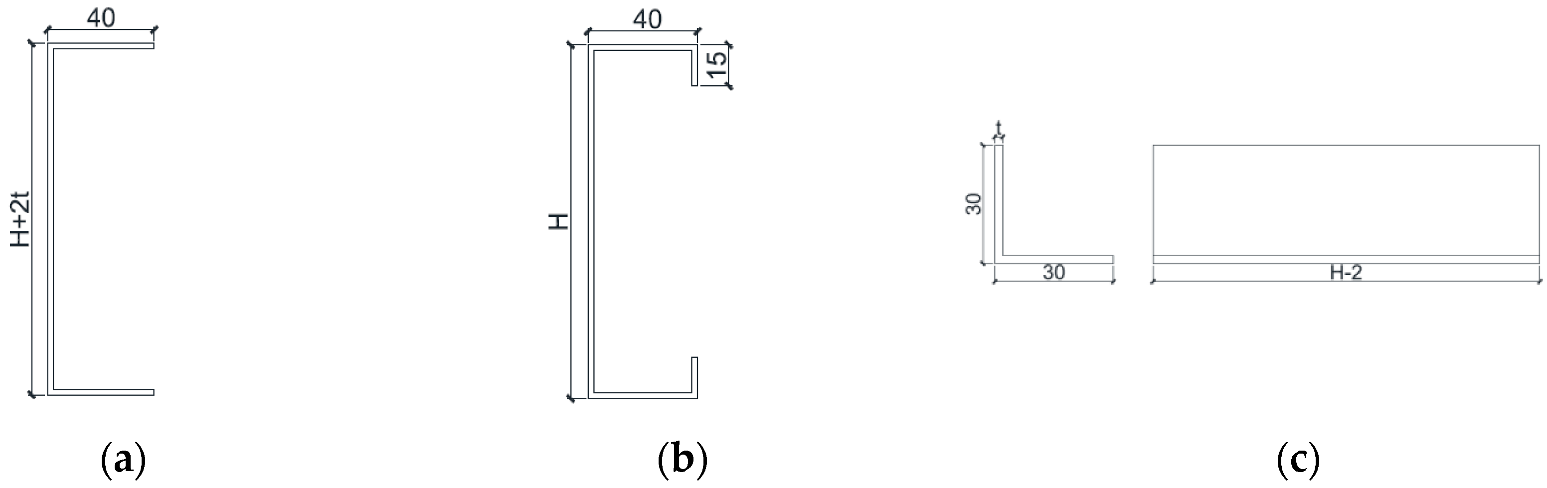
2.1. Designed Specimens
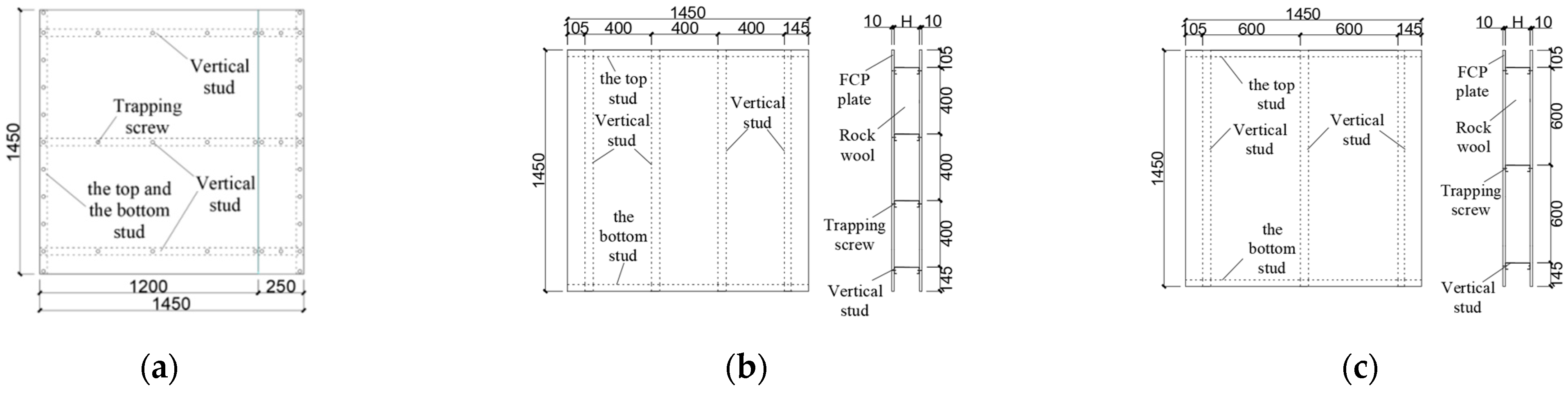
2.2. Assembled Specimens
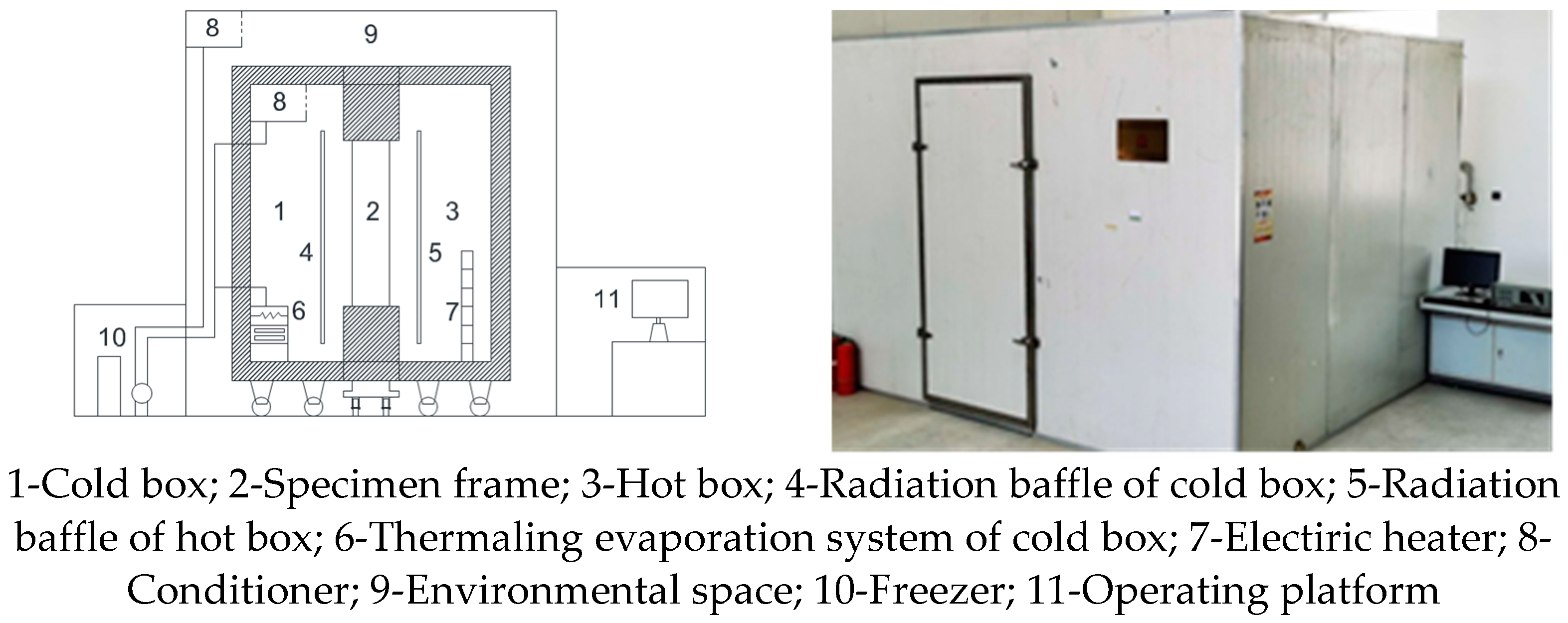
2.3. Test Device
2.4. Test Principle
3. Test Results
4. Finite Element Analysis
4.1. Establishment of Finite Element Model
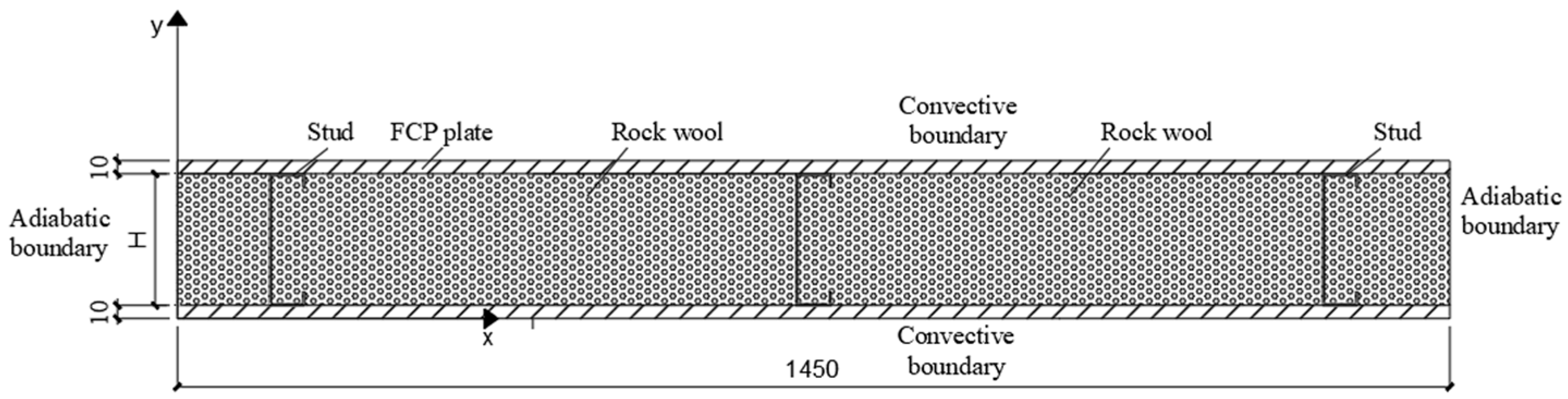
4.1.1. Plane Schematic Diagram of Model
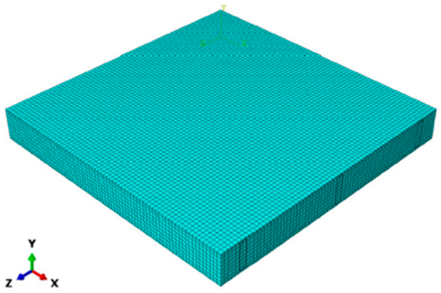
4.1.2. Plane Schematic Diagram of Model
- (1)
- In the finite element modeling analysis, only thermal conduction and convection were considered, whereas the radiation effect was ignored. The edges of the specimens did not thermally dissipate. The selected materials were used to minimize the effects of radiation. Therefore, the effect of radiation on the thermal transfer analysis could be ignored relative to that of the thermal convection;
- (2)
- The temperature and thermal flux at the contact surface were continuous, regardless of the influence of the contact thermal resistance caused by the gap between the materials in contact;
- (3)
- It was assumed that the materials in the light-gauge steel stud with the slotted web were homogeneous and isotropic, and that their material properties did not vary with changes in external temperature, humidity, and pressure.
4.1.3. Thermal Parameters of Materials
4.1.4. Contact Relation and Boundary Conditions
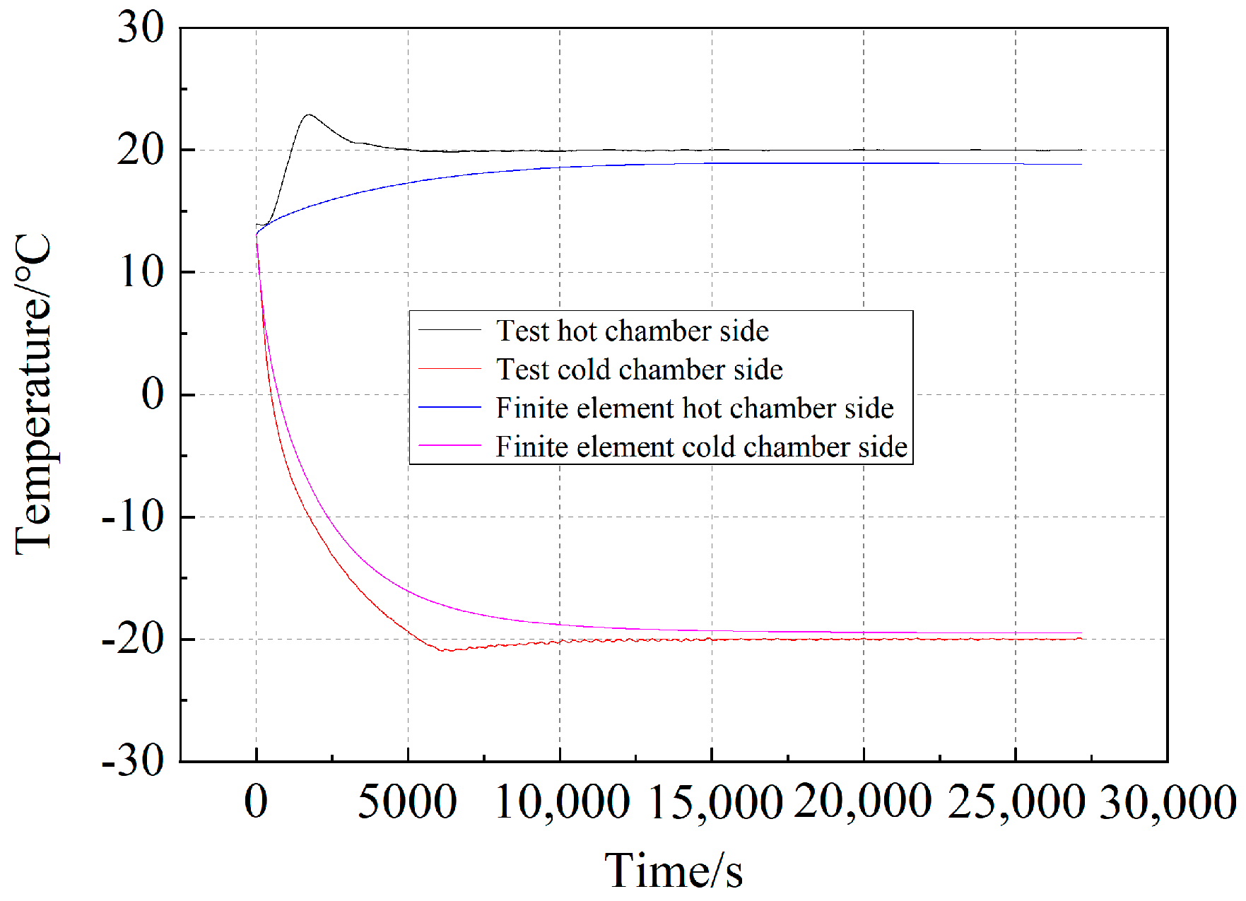
4.2. Validation of Model
4.3. Parameter Analysis
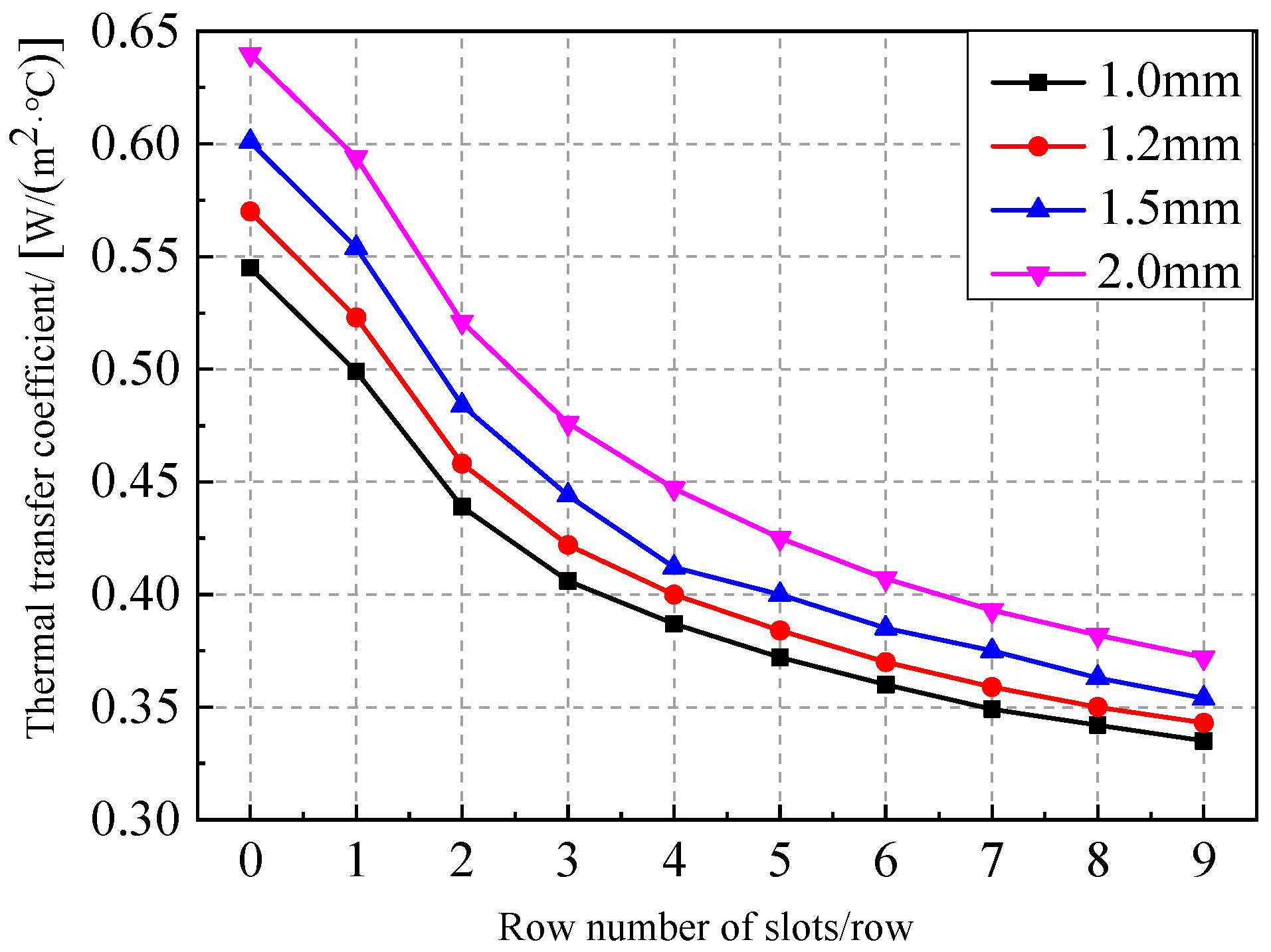
4.3.1. Number of Slot Rows
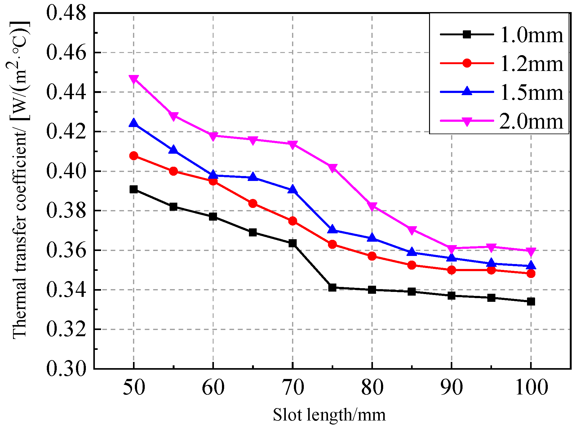
4.3.2. Slot Length
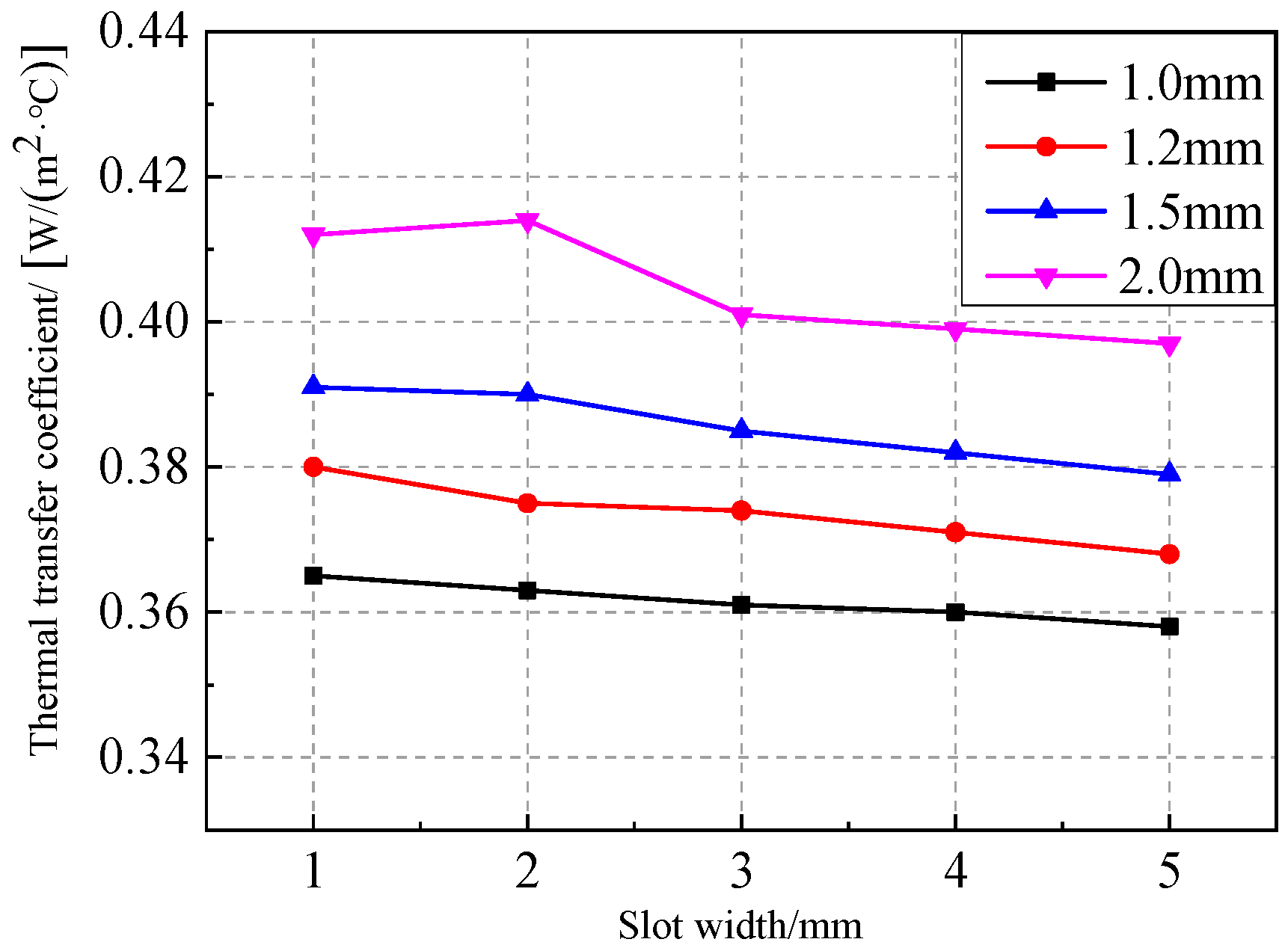
4.3.3. Slot Width
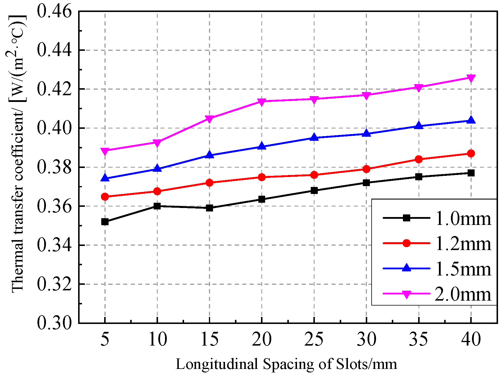
4.3.4. Longitudinal Spacing of Slots
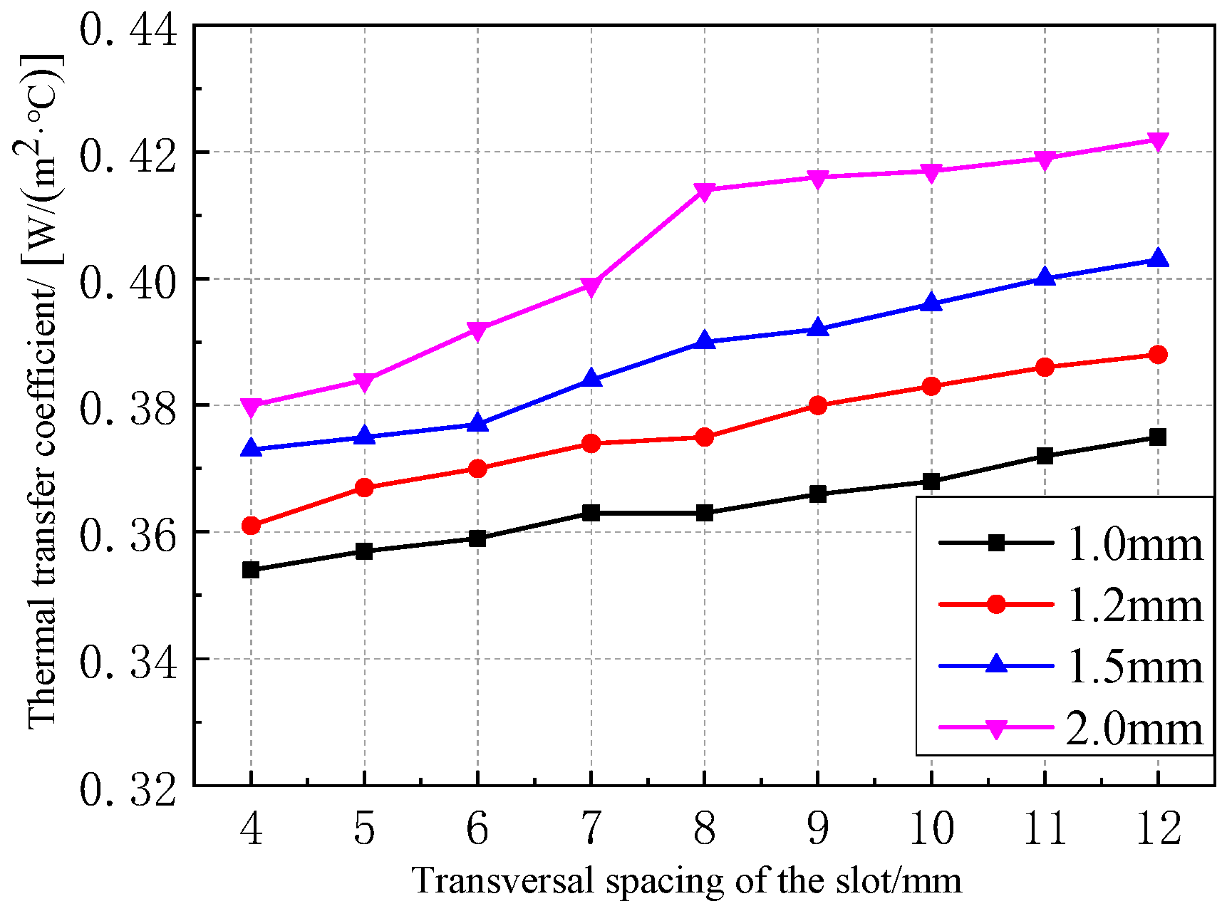
4.3.5. Transversal Spacing of Slots
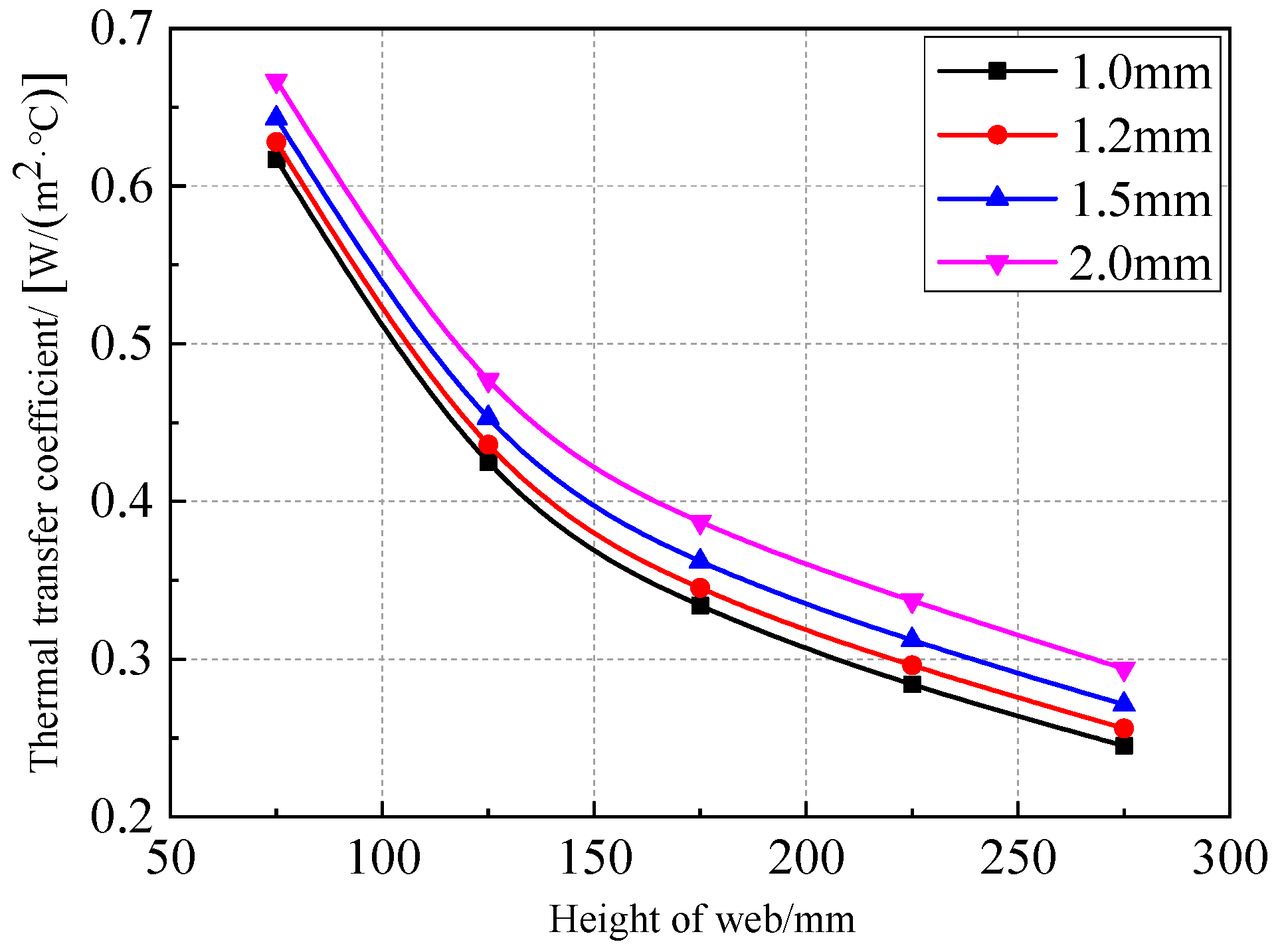
4.3.6. Height of Stud Web
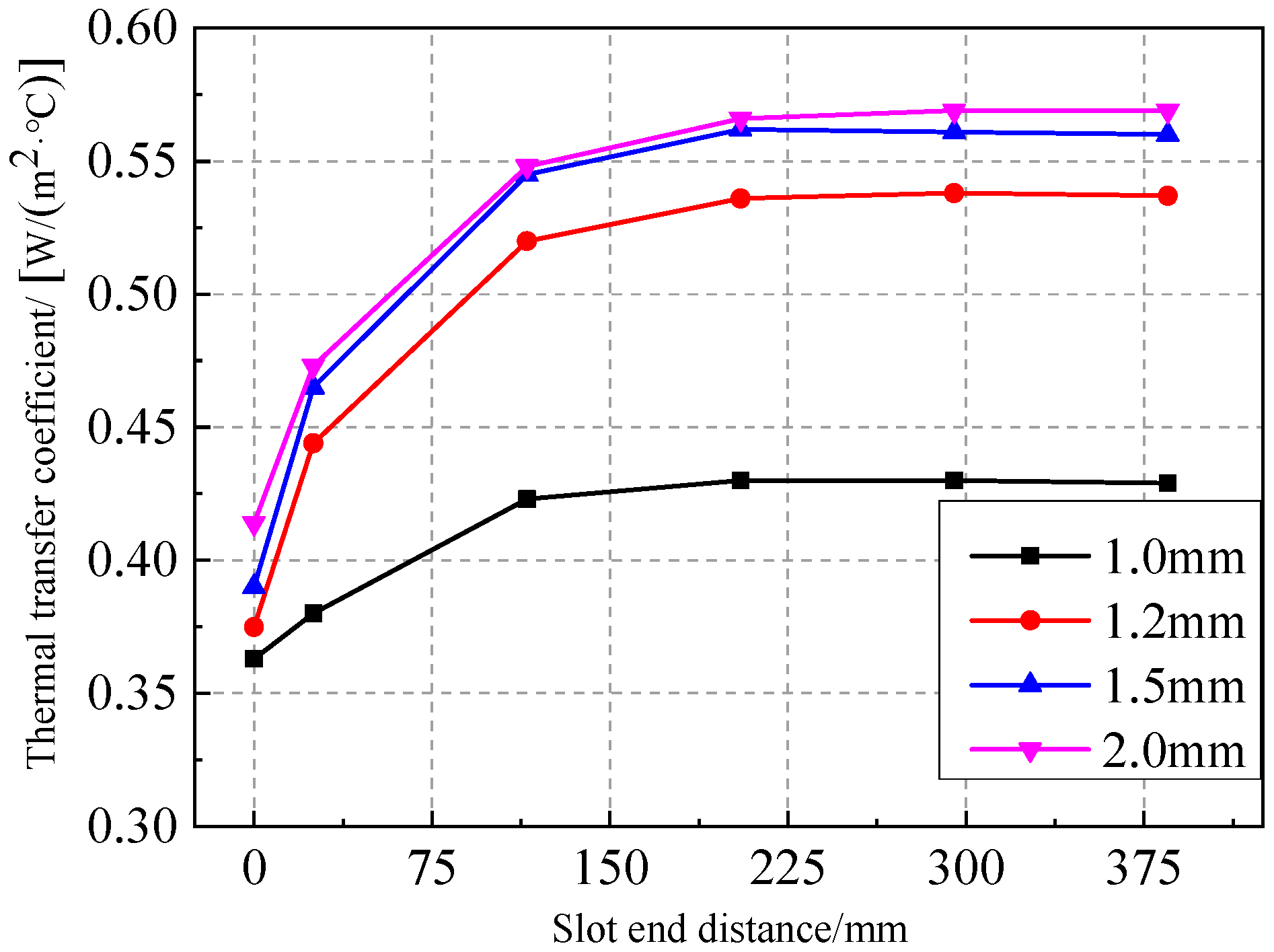
4.3.7. Slot End Distance
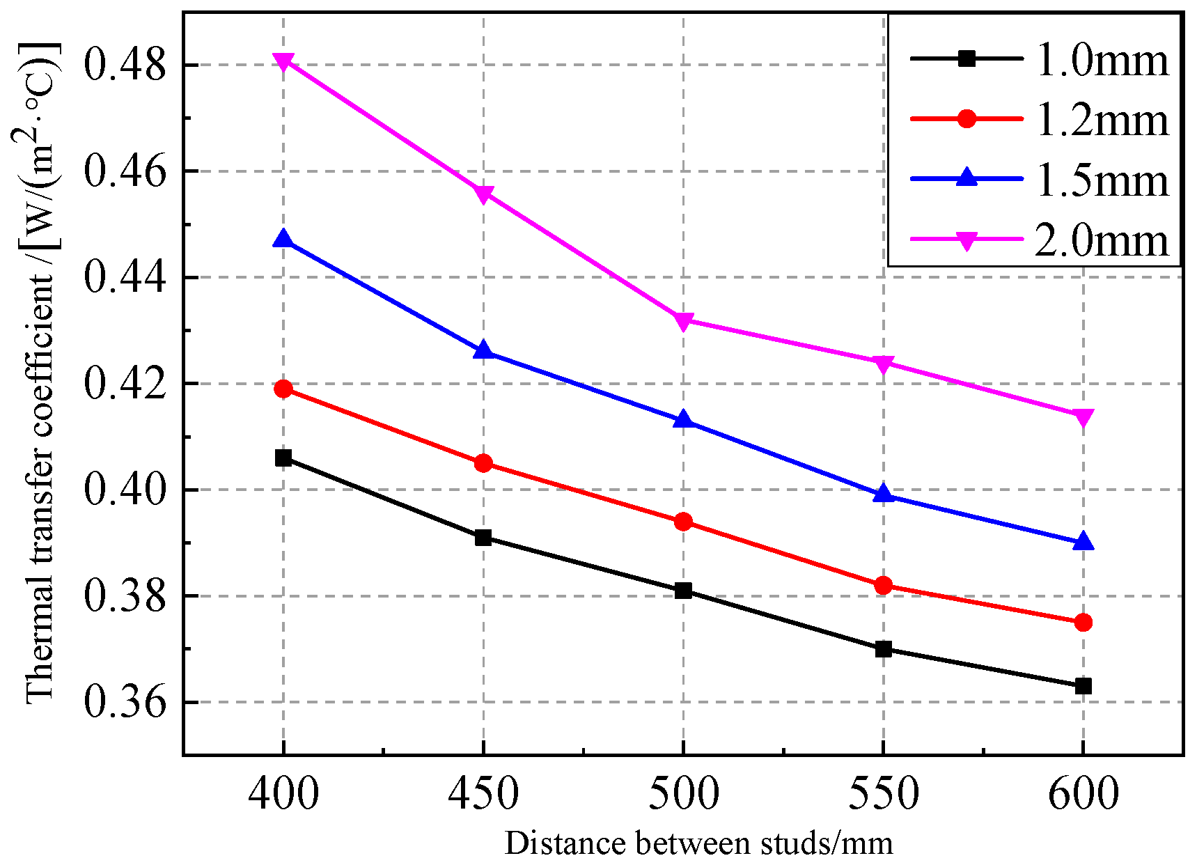
4.3.8. Stud Spacing
5. Conclusions
- When the thickness of the stud decreases by 0.5 mm, the wall heat transfer coefficient decreases by 18.63%. Compared with no slots, the heat transfer coefficient of a wall with seven rows of slows decreases by 38.59%. When the slot length increases by 40 mm, the heat transfer coefficient of the wall decreases by 24.19%. When the transverse spacing decreases by 4 mm, the wall heat transfer coefficient decreases by 16.04%. When the stud spacing increases by 200 mm, the wall heat transfer coefficient decreases by 6.75%. When the height of the stud web increases by 100 mm, the heat transfer coefficient of the wall decreases by 44.98%;
- The width of the slots has little influence on the heat transfer coefficient of the light steel stud wall, whereas the transverse spacing has a great influence on the heat transfer coefficient of light-gauge steel stud wall. When the number of slot rows exceeds four, the slot length exceeds 80 mm, the longitudinal distance is 10–25 mm, the distance between slot ends exceeds 205 mm, and the distance between studs exceeds 600 mm, there is little influence on the heat transfer coefficient of the light-gauge steel stud wall;
- For an actual project, the thickness of light steel stud should be 1.0 mm or 1.2 mm, the number of slot rows should be 5–7, the length of the opening should be 70–80 mm, the width of the opening should be 2–3 mm, the longitudinal spacing of the opening should be 20–30 mm, the transverse spacing of the opening should be 6–10 mm, the end distance should be 0, and the spacing of the studs should be 600 mm;
- Application of Slotted Light Steel-Framed Composite Wall to industrial buildings, pending field testing of their corrosion and thermal and moisture insulation performance, as well as evaluation of comprehensive energy consumption and thermal stability.
Author Contributions
Funding
Data Availability Statement
Conflicts of Interest
Nomenclature
| A | the specimen area |
| FCP | fiber cement pressure |
| H | Height of Stud |
| L | Length of Slots |
| M1 | the thermal flow coefficient of the outer wall of the hot box |
| M2 | the thermal flow coefficient of the specimen frame |
| U | Thermal Transfer Coefficient |
| Q | the thermal power of the heater |
| RN | Row Number of Slots |
| S | Spacing of Studs |
| T | Thickness of Stud |
| TS | Transversal Spacing of Slot |
| tb | the mean temperature of the air in the hot box |
| tc | the mean temperature of the air in the cold box |
| the difference in the weighted mean temperature between the inner and outer surface areas of the outer wall of the hot box | |
| the difference in the weighted mean temperature of the surface area of the hot side and cold side of the specimen frame |
References
- Zhai, X.; Wang, Y.; Wang, X. Thermal performance of precast concrete sandwich walls with a novel hybrid connector. Energy Build. 2018, 166, 109–121. [Google Scholar] [CrossRef]
- Roque, E.; Vicente, R.; Almeida, R.; Ferreira, V.M. Energy consumption in intermittently heated residential buildings: Light Steel Framing vs hollow brick masonry constructive system. J. Build. Eng. 2021, 43, 103024. [Google Scholar] [CrossRef]
- Soares, N.; Santos, P.; Gervasio, H.; Costa, J.J.; Simões da Silva, L. Energy efficiency and thermal performance of lightweight steel-framed (LSF) construction: A review. Renew Sust. Energ. Rev. 2017, 78, 194–209. [Google Scholar] [CrossRef]
- Veljkovic, M.; Johansson, B. Light steel framing for residential buildings. Thin. Wall Struct 2006, 44, 1272–1279. [Google Scholar] [CrossRef]
- Angelis; Serra, E. Light steel-frame walls: Thermal insulation performances and thermal bridges. Energy Proced. 2014, 45, 362–371. [Google Scholar] [CrossRef] [Green Version]
- Kosny, J.; Christian, J.E. Reducing the uncertainties associated with using the ASHRAE zone method for R-value calculations of metal frame walls. ASHRAE Trans. 1995, 101, 779–788. [Google Scholar]
- Kosny, J.; Christian, J.E. Thermal evaluation of several configurations of insulation and structural materials for some metal stud walls. Energy Build. 1995, 22, 157–163. [Google Scholar] [CrossRef]
- Salonvaara, M.; Nieminen, J. Hydrothermal performance of a new light gauge steel-framed envelope system. ASHRAE Trans. 1998, 104, 1256–1262. [Google Scholar]
- Barbour, C.E.; Goodrow, J. The thermal performance of steel-framed walls. ASHRAE Trans. 1995, 101, 766–778. [Google Scholar]
- Brown, W.C.; Swinton, M.C.; Haysom, J.C. A technique for calculating the effective thermal resistance of steel stud walls for code compliance. ASHRAE Trans. 1998, 104, 1245–1255. [Google Scholar]
- Manzan, M.; Zorzi, E.D.; Lorenzi, W. Numerical simulation and sensitivity analysis of a steel framed internal insulation system. Energ. Build. 2018, 158, 1703–1710. [Google Scholar] [CrossRef] [Green Version]
- Syed, A.M.; Kosny, J. Effacet of framing factor on clear wall r-value for wood and steel framed walls. J. Build. Phys. 2006, 30, 163–180. [Google Scholar] [CrossRef]
- Santos, P.; Martins, C.; Simoes, D.S. Thermal performance of lightweight steel-framed construction systems. Metall. Res. Technol. 2014, 111, 329–338. [Google Scholar] [CrossRef]
- Santos, P.; Martins, C.; Silva, L.; Bragança, L. Thermal performance of lightweight steel framed wall: The importance of flanking thermal losses. J. Build. Phys. 2014, 38, 81–98. [Google Scholar] [CrossRef] [Green Version]
- Martins, C.; Santos, P.; Silva, L.S. Lightweight steel-framed thermal bridges mitigation strategies: A parametric study. J. Build. Phys. 2016, 39, 342–372. [Google Scholar] [CrossRef]
- Lupan, L.M.; Manea, D.L.; Moga, L.M. Improving thermal performance of the wall panels using slotted steel stud framing. Proced. Technol. 2016, 22, 351–357. [Google Scholar] [CrossRef] [Green Version]
- Cong, L.; Xiaoyong, M.; Lin, H.; Xin, C.; Yu, Y.; Jian, Y. A new demountable light-gauge steel framed wall: Flexural behavior, thermal performance and life cycle assessment. J. Build. Eng. 2022, 47, 103856. [Google Scholar]
- JC/T 412.1–2018; The Fiber Cement Plate Part 1: Asbestos-Free Fiber Cement Plate. China Building Materials Industry Press: Beijing, China, 2018.
- GB50176–2016; The Code for Thermal Design of Civil Buildings. China Construction Industry Press: Beijing, China, 2016.


| No. | H/mm | T/mm | RN | L/mm | TS/mm | S/mm |
|---|---|---|---|---|---|---|
| TFCP-1 | 150 | 2.0 | 7 | 70 | 8 | 600 |
| TFCP-2 | 150 | 1.5 | 7 | 70 | 8 | 600 |
| TFCP-3 | 150 | 1.0 | 7 | 70 | 8 | 600 |
| TFCP-4 | 150 | 1.0 | 7 | 50 | 8 | 600 |
| TFCP-5 | 150 | 1.0 | 7 | 90 | 8 | 600 |
| TFCP-6 | 150 | 1.0 | 7 | 70 | 6 | 600 |
| TFCP-7 | 150 | 1.0 | 7 | 70 | 10 | 600 |
| TFCP-8 | 150 | 1.0 | 7 | 70 | 8 | 400 |
| TFCP-9 | 150 | 1.0 | No slot | - | - | 600 |
| TFCP-10 | 100 | 1.0 | 4 | 70 | 8 | 600 |
| TFCP-11 | 200 | 1.0 | 9 | 70 | 8 | 600 |
| Specimen No. | Temperature Difference between Inside and Outside/°C | Hot Chamber Power/W | U/[W/(m2·°C)] | Error | |
|---|---|---|---|---|---|
| Test | Simulation | ||||
| TFCP-1 | 39.50 | 58.36 | 0.526 | 0.440 | 16.3 |
| TFCP-2 | 39.66 | 55.92 | 0.492 | 0.401 | 18.5 |
| TFCP-3 | 39.56 | 49.38 | 0.428 | 0.377 | 11.9 |
| TFCP-4 | 39.73 | 49.98 | 0.434 | 0.412 | 5.1 |
| TFCP-5 | 39.70 | 40.39 | 0.329 | 0.349 | −6.1 |
| TFCP-6 | 39.68 | 48.80 | 0.424 | 0.368 | 13.2 |
| TFCP-7 | 39.61 | 56.29 | 0.505 | 0.378 | 25.1 |
| TFCP-8 | 39.80 | 52.82 | 0.459 | 0.406 | 11.5 |
| TFCP-9 | 39.53 | 75.98 | 0.697 | 0.667 | 4.3 |
| TFCP-10 | 39.57 | 68.89 | 0.638 | 0.550 | 13.8 |
| TFCP-11 | 39.71 | 43.01 | 0.351 | 0.291 | 17.1 |
| Name of Materials | Dry Density/(kg/m3) | Thermal Conductivity/[W/(m·°C)] | Specific Thermal Capacity/[J/(kg·°C)] |
|---|---|---|---|
| Rock Wool | 120 | 0.045 | 1220 |
| Light-gauge Steel Stud Structure | 7850 | 58.2 | 480 |
| Fiber Cement Pressure Plate | 1640 | 0.34 | 2510 |
Disclaimer/Publisher’s Note: The statements, opinions and data contained in all publications are solely those of the individual author(s) and contributor(s) and not of MDPI and/or the editor(s). MDPI and/or the editor(s) disclaim responsibility for any injury to people or property resulting from any ideas, methods, instructions or products referred to in the content. |
© 2023 by the authors. Licensee MDPI, Basel, Switzerland. This article is an open access article distributed under the terms and conditions of the Creative Commons Attribution (CC BY) license (https://creativecommons.org/licenses/by/4.0/).
Share and Cite
Yang, Z.; Sun, L.; Nan, B.; Wei, S. Thermal Performance of Slotted Light Steel-Framed Composite Wall. Energies 2023, 16, 2482. https://doi.org/10.3390/en16052482
Yang Z, Sun L, Nan B, Wei S. Thermal Performance of Slotted Light Steel-Framed Composite Wall. Energies. 2023; 16(5):2482. https://doi.org/10.3390/en16052482
Chicago/Turabian StyleYang, Zhijian, Lisuo Sun, Bo Nan, and Shunli Wei. 2023. "Thermal Performance of Slotted Light Steel-Framed Composite Wall" Energies 16, no. 5: 2482. https://doi.org/10.3390/en16052482