1. Introduction
Floating offshore wind turbines are a relatively young and growing technology domain that can play a significant role in decarbonizing the energy sector, particularly in geographic areas where a deep-water wind resource exists. However, additional research and development are needed to reduce the levelized cost of energy (LCOE) of floating offshore wind installations. This goal requires verified and validated design tools to optimize floating offshore wind turbines and reduce their cost. One commonly used open-source floating offshore wind turbine design and analysis tool is OpenFAST, an aero-hydro-servo-elastic solver developed and maintained by the National Renewable Energy Laboratory (NREL) [
1]. OpenFAST is continuously being expanded to support many types of mooring systems, floating platform archetypes, and floating system dynamics and controls. OpenFAST has been extensively verified and validated for three-bladed, horizontal-axis, upwind turbines (HAWTs), but supports limited capability for vertical-axis wind turbines (VAWTs).
Vertical-axis wind turbines have a long history, with a wide variety of turbine archetypes, including the common Darrieus and H-type rotors [
2]. While few utility-scale VAWTs currently exist, VAWTs offer some potential advantages over HAWTs, such as being agnostic to the direction of the wind (no yaw error), reduced downstream wake, aerodynamic synergy between turbines in a closely spaced farm, and lower placement of the generator [
3]. Recent design studies show that these advantages could provide particular benefit for floating offshore wind turbines, as floating VAWTs have been shown to potentially provide a greater than 20% reduction in LCOE compared to a floating HAWT of equivalent power [
4,
5].
This development, in addition to increasing interest in leveraging VAWTs for distributed wind applications [
2], has spurred renewed interest in VAWT research in the last decade. As Sutherland et al. highlighted the need to optimize commercial-scale designs for VAWTs following the relative absence of the technology since the 1990s [
6], researchers have concentrated on developing improved computer software for VAWTs capable of numerically modeling onshore and offshore operation. Researchers have developed and validated several software tools for dynamic floating VAWT simulation, including DeepLines from Principia and IFP Energies Nouvelles [
7,
8], SIMO-RIFLEX-AC by Cheng et al. [
9], FloVAWT by Collu et al. [
10], and QBLADE by Marten et al. [
11,
12]. Owens developed the Offshore Wind ENergy Simulator (OWENS) for aero-hydro-servo-elastic VAWT simulation [
13], which is currently under further development by Sandia National Laboratories (Sandia).
However, the relatively poor penetration of VAWT technology has kept the validation of these software tools limited, typically using workarounds such as using HAWTs instead of VAWTs or by testing the software in a modularized approach where the aerodynamics, structural dynamics, and hydrodynamics are testing separately of one another. Additionally, validation against VAWT experimental data is scant due to the relative absence of modern experimental testing, especially for floating applications. Howell et al. performed an early comparison of the theoretical tip-speed ratio and rotor performance of a small-scale VAWT in a wind tunnel against CFD and FEA codes, using Fluent and Gambit, respectively [
14]. Marten et al. validated the blade performance within QBLADE against historical land-based VAWT data [
11]. Recently, Moore and Ennis have validated the aerodynamics and two-way aero-elastic coupling of OWENS against historical Sandia VAWT data, presenting the most comprehensive validation of a VAWT numerical model to date [
15,
16].
In efforts to continue to improve and validate the OWENS engineering toolset, this work focuses on the development and testing of improved hydrodynamics and mooring dynamics functionality within OWENS. OWENS is currently capable of simulating hydrodynamic and mooring loading for a floating VAWTs via coupling to a modified version of WavEC2Wire [
17], but the coupling is not maintained, and the coupling framework used for this in OWENS does not easily allow for coupling to other more common hydrodynamic solvers for offshore wind. To enhance the floating capabilities and user experience of OWENS, an upgrade to the coupling tool is needed. This article describes the coupling of OWENS to the HydroDyn and MoorDyn modules from OpenFAST to improve the coupled aero-hydro-servo-elastic modeling of floating offshore VAWTs and discusses the verification of a coupled OWENS simulation against OpenFAST. The primary goal of this effort is to facilitate the continuing development of OWENS by introducing and validating additional capabilities for floating VAWT applications. By coupling HydroDyn and MoorDyn, OWENS can now model a floating substructure as a rigid body with hydrodynamics and mooring dynamics, thereby enabling studies of the dynamics of the coupled turbine–platform system using validated open-source design tools that are continuously maintained and improved. This article documents the model development (
Section 2), as well as the verification procedure and results using the OC4 semi-submersible test case of the upgraded OWENS tool, compared to OpenFAST v3.1.0 (
Section 3).
2. Numerical Methods
This section describes the existing capabilities and modules of OWENS and OpenFAST relevant to this work, and the methodology used to couple the two programs to enable time domain simulation. To provide context for the following subsections, a module comparison between the software programs is shown in
Table 1.
2.1. OWENS
OWENS is an engineering toolset for VAWT aero-hydro-servo-elastic numerical simulation written in the Julia programming language. OWENS uses a modular framework that interfaces structural dynamics, aerodynamics, servo-dynamics, hydrodynamics, and mooring dynamics modules to predict the full system response of a land-based or floating VAWT, with a block-Gauss–Seidel iterative method to stabilize results across modules. It can model and analyze a wide variety of VAWT configurations and composite structures in both the modal and unsteady domains with full two-way coupling between all subsystems. Additionally, the software is written so much of the code can propagate automatic gradients, thus enabling significant enhancements for numerical optimization approaches.
2.1.1. Structural Solver
GyricFEA is the structural dynamics module encompassing the original functionality of OWENS. Using a user-defined finite element mesh and structural properties, GyricFEA predicts the elastic deformation of a VAWT of any arbitrary configuration subject to external and inertial forces. The module uses a robust finite element method, applying Timoshenko beam theory to each element of a VAWT using a Newmark-β method to solve for the element dynamics in the reference frame of the VAWT rotor. GyricFEA can also account for rigid body displacements of a VAWT on a floating platform by applying spin softening and Coriolis forces to the structure.
2.1.2. Aerodynamics
The aerodynamics portion of OWENS, VAWTAero, includes a set of reformulated actuator cylinder and double multiple streamtube models that overcome previous issues regarding accuracy for 3D curved blades, and an improved numerical method for unsteady analysis [
15]. These methods are coupled and validated for two-way coupled aero-elastic analysis [
16]. One-way coupling to the vortex method tool CACTUS has also been maintained as an option.
The coupling of OWENS with AeroDyn, the aerodynamics module in OpenFAST, is also under development through a separate project. This coupling will enable OWENS to make use of the aerodynamic modeling capability recently implemented in OpenFAST for VAWTs, including two-way coupling to a free-wake vortex method coupled to multiple unsteady airfoil aerodynamics models.
2.1.3. Servo Dynamics
OWENS includes a basic interface to calculate the generator and drivetrain torque based on the user-defined drivetrain stiffness, damping, and control torque law. The program is also able to interface with custom profiles provided by users for dictating the generator and drivetrain response. Features including additional control systems are under development.
2.1.4. Hydrodynamics and Moorings
OWENS is coupled to a modified version of the WavEC2Wire software developed by Marco Alves, with the drivetrain PTO loads replaced by the tower base reaction loads [
17]. WavEC2Wire receives the tower base reaction loads as inputs from GyricFEA, calculates the effects of the hydrodynamics and mooring of a user-defined platform, and returns the platform motions to GyricFEA. However, this current approach presents various shortcomings. First, the coupling requires users to set up and run a simulation of the modified version of WavEC2Wire simultaneously with an OWENS simulation on another computer, which presents significant overhead and accessibility issues for many users. Second, many standard hydrodynamic modeling tools for floating wind systems (including OpenFAST) use rigid body motions of the platform as inputs, while this coupling requires OWENS to instead use tower base reaction loads as inputs, limiting the capability of OWENS to be coupled to many other existing hydrodynamics design tools. Additionally, the version of WavEC2Wire applied in previous work is limited to a linear wave model and a quasi-static mooring function, impacting the accuracy of simulations of extreme and fatigue loading conditions.
2.2. OpenFAST
OpenFAST is a physics-based engineering tool for simulating the coupled dynamic response of wind turbines in various wind and wave environments [
1]. OpenFAST provides the framework that couples physics-based engineering modules for aerodynamics, multimember, multibody hydrodynamics, control and electrical system (servo) dynamics, and structural dynamics to enable coupled nonlinear aero-hydro-servo-elastic simulation in the time domain. OpenFAST enables the analysis of a range of wind turbine configurations, including two- or three-blade horizontal-axis rotor, pitch or stall regulation, rigid or teetering hub, upwind or downwind rotor, and lattice or tubular tower. The wind turbine can be modeled on land or offshore on fixed-bottom or floating substructures. OpenFAST also supports linearization of the solution. The OpenFAST modules that have been coupled to OWENS through this work are as follows:
2.2.1. InflowWind
InflowWind is a module for processing different types of wind-inflow that are supported by OpenFAST. InflowWind supports arbitrary wind directions and several wind file formats, including uniform, binary TurbSim full field, binary Bladed-style full field, and HAWC formatted binary full-field turbulent wind files. Additionally, InflowWind supports an internally calculated steady wind model. Uniform wind files support simulations involving deterministic transient gusts. Turbulent full-field wind files support spatially and temporally varying wind inflow.
At each time step, InflowWind receives from either the stand-alone driver code or OpenFAST the coordinate position of various points, and then InflowWind returns the undisturbed wind-inflow velocities at these positions. There are no states in the module: each wind velocity component is calculated as a function of the input coordinate positions and internal time-varying parameters, undisturbed from interacting with the wind turbine. For full-field turbulent wind data types, InflowWind uses Taylor’s frozen turbulence hypothesis—valid only for stationary conditions—to translate wind defined in two-dimensional planes into three spatial dimensions, using the mean wind speed as the advection speed.
2.2.2. HydroDyn
HydroDyn is a hydrodynamics module applicable to both fixed-bottom and floating offshore substructures [
18]. HydroDyn allows for multiple approaches to calculating the hydrodynamic loads on a structure: a potential-flow theory solution, a strip-theory solution, or a hybrid combination of the two. Waves generated internally within HydroDyn can be regular (periodic) or irregular (stochastic), and long-crested (unidirectional) or short-crested (with wave energy spread across a range of directions). Wave elevations or full wave kinematics can also be generated externally and used within HydroDyn. Internally, HydroDyn generates waves analytically for finite depths using first-order (linear Airy) or first- plus second-order wave theory [
19] with the option to include directional spreading, albeit with wave kinematics only computed in the domain between the flat seabed and still water level. Wave stretching will also be introduced in an upcoming version. The second-order hydrodynamic implementations include time-domain calculations of difference-frequency terms (mean- and slow-drift) and sum-frequency terms. To minimize computational expense, fast Fourier transforms (FFTs) are applied in the summation of all wave frequency components.
The potential-flow solution is applicable to multiple bodies and/or substructures or members of substructures that are large relative to a typical wavelength and amplitude, assuming an inviscid, irrotational, incompressible fluid in constant water depth. The potential-flow solution involves either frequency-to-time-domain transforms or fluid-impulse theory. In the former, potential-flow hydrodynamic loads include linear hydrostatic restoring, the added mass and damping contributions from linear wave radiation (including free-surface memory effects), and the incident-wave excitation from first- and second-order diffraction (Froude-Krylov and scattering). The hydrodynamic coefficients (first and second order) required for the potential-flow solution are frequency-dependent and must be supplied by a separate frequency-domain panel code (e.g., WAMIT) from a precomputation step. The radiation memory effect can be calculated either through direct time-domain convolution or through a linear state-space approach, with a state-space model derived through the SS_Fitting preprocessor. A state-space option was recently added for wave excitation as well. The second-order terms can be derived from the full difference- and sum-frequency quadratic transfer functions (QTFs) or the difference-frequency terms can be estimated via Standing et al.’s extension to Newman’s approximation, based only on first-order coefficients [
20]. The use of fluid-impulse theory is not yet documented.
The strip-theory solution may be preferable for substructures or members of substructures that are small in diameter relative to a typical wavelength. Strip-theory hydrodynamic loads can be applied across multiple interconnected members, each with possible incline and taper, and are derived directly from the undisturbed wave and current kinematics at the displaced position of the substructure. The strip-theory loads include the relative form of Morison’s equation for the distributed fluid-inertia, added-mass, and viscous-drag components. Additional distributed load components include axial loads from tapered members and static buoyancy loads about the displaced position. Hydrodynamic loads can also be applied as lumped loads on member endpoints (joints). It is also possible to include flooding or ballasting of members, and the effects of marine growth. The hydrodynamic coefficients required for this solution come through user-specified dynamic-pressure, added-mass, and viscous-drag coefficients.
The analysis of many substructures and sea conditions applicable to floating offshore wind can be made more accurate by augmenting the hydrodynamic loads from a potential-flow theory with the loads brought on due to viscous effects from a strip-theory solution. For this, the viscous-drag component of the strip-theory solution may be included with the potential-flow theory solution in HydroDyn. Another option available is to supply a global damping matrix (linear or quadratic) to the system to represent this effect.
When HydroDyn is coupled to OpenFAST or OWENS, HydroDyn receives the position, orientation, velocities, and accelerations of the (rigid or flexible) substructure at each coupling time step and then computes the hydrodynamic loads (including added mass) and returns them back to OpenFAST or OWENS.
2.2.3. MoorDyn
MoorDyn is an open-source lumped-mass mooring line model that can be driven independently or by OpenFAST. MoorDyn supports arbitrary line interconnections, clump weights and floats, and different line properties. The model accounts for internal axial stiffness and damping forces, weight and buoyancy forces, hydrodynamic forces from Morison’s equation, and vertical spring-damper forces from contact with the seabed. The formulation supports inclusion of wave kinematics in the hydrodynamic force calculations when coupled to HydroDyn in OpenFAST, but this feature is not presently included in the coupling to OWENS.
MoorDyn uses a lumped-mass approach to discretize the cable dynamics over the length of the mooring line. A cable is broken up into N uniformly sized line segments connecting N + 1 node points. Each segment of the cable has identical properties of unstretched length, diameter, density, and Young’s modulus. Different cables can have different sets of properties, and cables can be connected at the ends, enabling mooring systems with interconnected lines.
Hydrodynamic loads are calculated directly at the node points rather than at the segment centers. This ensures damping of transverse cable vibrations having a wavelength of twice the cable segment length. To approximate the cable direction at the node points, the cable tangent at each node is assumed to be the average of the tangent directions of the two adjacent cable elements.
2.3. Numerical Interface Architecture
The core algorithms of the OpenFAST modules are written in Fortran, while OWENS is written in pure Julia. Julia can call C code directly, so we developed a C-based module interface to enable the OpenFAST modules to communicate with OWENS. The calling interface libraries described herein are specific to the Julia, and new libraries will need to be generated for other languages to communicate properly with the Fortran module library.
As the OpenFAST modules have been previously verified and validated independent of this work, we desired to modify the existing Fortran modules as little as possible. Instead, we developed new wrappers that pass data appropriately between OpenFAST modules and C-based drivers.
Figure 1 illustrates the relationship between the Fortran module subroutines of OpenFAST and OWENS, using HydroDyn as an example. A new Fortran-C module interface library (HydroDyn_C), written in Fortran, is needed to convert Fortran data types into C-based data types, store data used internally in HydroDyn, and transition from pass by reference (Fortran) to pass by value (C). An interface library file in Julia, HydroDyn_Lib, is needed to interface the C code to a version readable by OWENS using the
ccall syntax in Julia.
In summary, we made the following high-level changes needed to couple each OpenFAST module to OWENS:
Wrote one new C-bindings interface library written in Fortran, interfacing OpenFAST to C,
Wrote one new C-Julia interface library, interfacing C to OWENS, and
Compiled a dynamic library to call the compiled C-bindings interface within the C-Julia interface library
We also wrote an external driver in Python to use as an example for each module for potential future bindings between OpenFAST modules and other C-based languages. In total, nine new files were written and added to both the OpenFAST and OWENS code repositories to support interfacing the OpenFAST HydroDyn, MoorDyn, and InflowWind modules with OWENS (the InflowWind coupling is not included in the OWENS verification test in
Section 3). A more detailed diagram is shown in
Figure 2, which also shows Python and Julia interface libraries.
2.3.1. OpenFAST Module Interface Library
The interface libraries and their associated calling libraries support the conversion of variable types, formats, and addressing when passing them through the function calls. The module interface libraries are written in Fortran and heavily use the Fortran ISO_C_BINDING module alongside the module source files. Each of the four main subroutines—Init(), UpdateStates(), CalcOutput(), and End()—are C-bound, using
The input and output variables are standardized according to the OpenFAST framework and include time indexing and state information. The overall flow of the script for each of the four main subroutines is as follows:
Convert the input variable types and formats;
Perform any preparation steps (initialization, allocation, etc.);
Call the associated main module subroutine;
Convert the output variable types and formats, set output variable values;
Clean up (deletion, deallocation, etc.).
Both MoorDyn and HydroDyn include the conversion of the multidimensional platform mesh in OpenFAST to a single point for OWENS, and vice versa. Performing this conversion correctly involved employing subroutines from the NWTC library and the module source files. These modules assume small angular displacements less than about +/− 17 degrees or less for platform motions (this limitation could be overcome with the use of full direction cosine matrices for the orientations but would require significant changes to the internal code).
The source code for OpenFAST module C-bindings interface libraries are available in the OpenFAST repository within the respective module source directory (i.e., modules/hydrodyn/src/HydroDyn_C_Bindings.f90 for HydroDyn). These may be compiled using the CMake build system or Visual Studio projects provided in the repository.
2.3.2. OWENS Module Interface Library
The interface libraries transitioning the C code to Julia is tightly coupled to its associated module interface library. The libraries make extensive use of the built-in C interface to Julia with the following structure:
Pass in variable values defined in the driver program;
For moduleName_updatestates(), moduleName_calccutput(), and moduleName_end(), verify the module has been initialized (i.e., confirm the moduleName_init() function has been called);
Convert input and output variable types between C and Julia using built-in Julia C types (Cfloat, Cstring, etc.);
Use the ccall function to access the C code with the converted inputs and in-place outputs;
Check for any errors that may have occurred at the Fortran level and handle them within Julia.
The libraries specific for calling each of the OpenFAST modules in OWENS are available in the OpenFASTWrappers.jl repository on GitHub [
21]. The example Python interfacing libraries for are available in the OpenFAST repository within the respective module source directory (i.e., modules/hydrodyn/python-lib/hydrodyn_library.py) [
22].
2.3.3. Example External Driver
The driver code to call the OpenFAST module subroutines within OWENS is described below in
Section 2.4, but is currently only accessible via a private Sandia repository. Instead, an example of the external driver file is included in the OpenFAST repository to demonstrate how to successfully call the module-specific subroutines within Python in a very similar manner. The driver file primarily utilizes the interface library file while minimizing additional dependencies. It supports .dll, .dylib, and .so files. Its overall structure is:
Import the module-specific interface library file;
Initialize and/or instantiate the class and variables;
Call moduleName_C_Init();
Step through time, calculating the outputs at each time step using moduleName_C_calcOutputs() and moduleName_C_updateStates();
When finished, close out and clean up with moduleName_C_End().
Examples of Python drivers calling the OpenFAST module libraries through the interfaces mentioned above are available as module level regression tests in the OpenFAST repository (i.e., reg_tests/r-test/modules/hydrodyn/hd_py_5MW_OC4Semi_WSt_WavesWN/hydrodyn_driver.py) [
22].
2.4. Numerical Coupling Algorithm
As OWENS and OpenFAST both utilize a loose coupling modularized framework, the integration of the OpenFAST modules into OWENS is theoretically relatively straightforward. However, as mentioned in
Section 2.1.4, the OWENS hydro-elastic coupling framework has previously assumed tower base loads to be the inputs for the coupled hydrodynamic module, while HydroDyn and MoorDyn expect rigid body motions of the floating platform as inputs. As a result, we substantially modified the hydro-elastic coupling methodology in the OWENS source code to enable coupling to HydroDyn and MoorDyn.
Section 2.4.1 discusses the modifications made to the hydro-elastic module interface within OWENS, allowing GyricFEA to interface with the HydroDyn and MoorDyn C-based libraries discussed above.
Section 2.4.2 discusses the interface changes to the meshing within GyricFEA required to his interface change requires OWENS to natively represent a floating platform. Finally,
Section 2.4.3 documents the changes made to the time domain simulation framework in the OWENS glue code to integrate the new hydro-elastic coupling methodology and meshing approach with its existing VAWT simulation capabilities.
2.4.1. Coupling Interface
Enabling OWENS to directly interface with the HydroDyn and MoorDyn interface libraries required several notable changes to its existing hydro-elastic coupling routine. First, we shifted the modular partitioning point from the tower base to the fluid-structure boundary at the platform. This is due to HydroDyn and MoorDyn expecting inputs and outputs at the platform reference point (a term derived from WAMIT), which is intractable if partitioning at the tower base. Second, we inverted the hydro-elastic I/O interface in OWENS, which required completely rebuilding the coupling framework within the glue code. This was accomplished by representing the platform as a separate mesh within the OWENS structural module GyricFEA, as GyricFEA natively receives external loads as inputs and returns motions as outputs. This meshing strategy is discussed in greater detail in the next section.
Finally, we replaced the method used to achieve numerical convergence and stability. This was needed because the previously used block-Gauss–Seidel method is ill-suited to handle the added mass term interfacing across the modules. Namely, the added mass contributions to the hydrodynamic loading on the platform are dependent on the accelerations of the platform (calculated in GyricFEA), but the accelerations of the platform are themselves dependent on the hydrodynamic loading (calculated in HydroDyn). The block-Gauss–Seidel method has no easy way to handle this tight coupling of the added mass in a way that will converge unconditionally when it is split across two modules [
23]. To resolve this, a new solve procedure has been implemented for the GyricFEA–HydroDyn coupling within OWENS using a block-Newton–Raphson solver to account for the residuals each program produces for its outputs as its inputs are perturbed. This is a very similar procedure used to couple HydroDyn to ElastoDyn within OpenFAST.
The Newton–Raphson solver procedure operates as follows:
GyricFEA calculates structural motions (including the platform accelerations and ) using the platform reference point loads extrapolated from the previous time step in six degrees of freedom. No platform loads are used on the first time step of the simulation.
MoorDyn calculates mooring loads in six degrees of freedom for the current time step using the structural motions computed in step 1.
The total platform loads from the previous time step (or zero, if it is the first time step of the simulation) and the platform motions from step 1 are saved to the input vector
, where
The platform loads saved in are divided by a factor of 1,000,000 to be in the same order of magnitude as the accelerations.
HydroDyn calculates the hydrodynamic loads
for the current time step, and GyricFEA calculates the structural motions (including the platform accelerations
and
) for the current time step. The new hydrodynamic loads are recombined with the mooring loads to get the new total platform loads:
The solver calculates the residual
between the outputs calculated in step 4 and
:
The solver calculates the Jacobian of , . Each column of is calculated by perturbing the primary causal load or acceleration input, running the relevant program to solve for the output, solving for the residual between the old outputs and the perturbed outputs, and taking the difference between and the new perturbed residual;
The change in loads/accelerations,
, is solved with
The solver updates
to
, with
GyricFEA and HydroDyn run again using the updated loads/accelerations contained in to get the final outputs at the current time, which are returned to the top-level glue code in OWENS as the time marching proceeds.
2.4.2. Updated OWENS Mesh
As OpenFAST and OWENS have substantially different structural solve procedures, coupling HydroDyn and MoorDyn to OWENS requires careful mesh representation and translation of different inputs and outputs. Fundamentally, the meshing approach in OWENS for a floating VAWT uses two finite element meshes:
A simple, three-node mesh representing the platform, with zero distributed mass, quasi-infinite stiffness, and two concentrated masses.
A complex mesh composed of many nodes, representing everything at the turbine base and above (i.e., the “topside”).
The locations of the three nodes represent the platform center of gravity, the platform reference point, and the turbine base (which must be the top node). The two concentrated masses on the platform mesh are the 6 × 6 mass matrices of the platform and topside, each representing the respective mass and inertia of each subsystem. The platform and topside concentrated masses are applied at the platform center of gravity and turbine base nodes, respectively. The hydrodynamic and mooring loads are applied at the platform reference node.
The coupling between the two meshes is shown in
Figure 3. The topside mesh has boundary conditions at the bottom node (the turbine base) fixing it into place, but the rigid body motions of the platform are received from the platform mesh at each time step and are used to:
Create the rotation matrix from the global to the hub reference frame (along with the hub rotation information at the current time step), which is used in the OWENS solver for the topside structure.
Generate the Coriolis and spin softening forces needed on the topside mesh to account for the deflection of the platform in the rotating hub reference frame, in addition to the force due to the acceleration of the platform.
This approach of separating the two meshes is taken for several reasons. First, representing a rigid body platform in the same finite element mesh as a more flexible topside results in a difference in stiffness of several orders of magnitude between different elements of the mesh, which can result in simulation instability. Second, the block-Newton–Raphson method used for the GyricFEA–HydroDyn coupling described in
Section 2.4.1 requires several calls to GyricFEA, which scales linearly with the number of elements. If the entire structure were represented in a single mesh, the many elements of the topside being evaluated in the block-Newton–Raphson approach would be computationally inefficient with no obvious gain. Finally, GyricFEA natively operates in the rotor reference frame, while the coupled OpenFAST modules operate in the global reference frame. Separating the two meshes allows the platform mesh to operate in the global reference frame and the topside mesh to operate in the rotor reference frame; the platform motions and tower base reaction loads only need to rotate at the transfer between the meshes, making the bookkeeping in the source code more straightforward.
2.4.3. Coupled OWENS Solution
The process flow between the two meshes is shown in
Figure 4. The topside mesh solves for structural motions using displacements from the previous time step and aerodynamic loads from the current time steps via a Newmark-β approach [
24], iterated using the Gauss–Seidel method until the difference between the nodal displacements and rotor rotation to the previous iteration are sufficiently small and can be considered converged. This is identical to the solution method GyricFEA has used previously in OWENS. Upon convergence, the opposite of the reaction loads at the tower base due to the aerodynamic loading (i.e., ignoring the effects of gravity) are transferred to the tower base node on the platform mesh as an external load, and the platform motions are solved using the block-Newton–Raphson method laid out above. The platform motions are then sent to the topside mesh, repeating the Gauss–Seidel/Newmark-β solve with the new platform motions now accounted for. The new converged results are saved and used to predict values for the next time step.
It is important to note that the topside mesh is evaluated in the hub reference frame while the platform mesh is evaluated in the global reference frame. Thus, the tower base reaction force is rotated into the global frame from the hub frame when transferring to the platform mesh, and vice versa for the platform motions when transferring to the topside mesh. The rotation matrix is extrapolated from the platform displacements and the rotor rotation is calculated in the previous time step.
4. Conclusions and Future Work
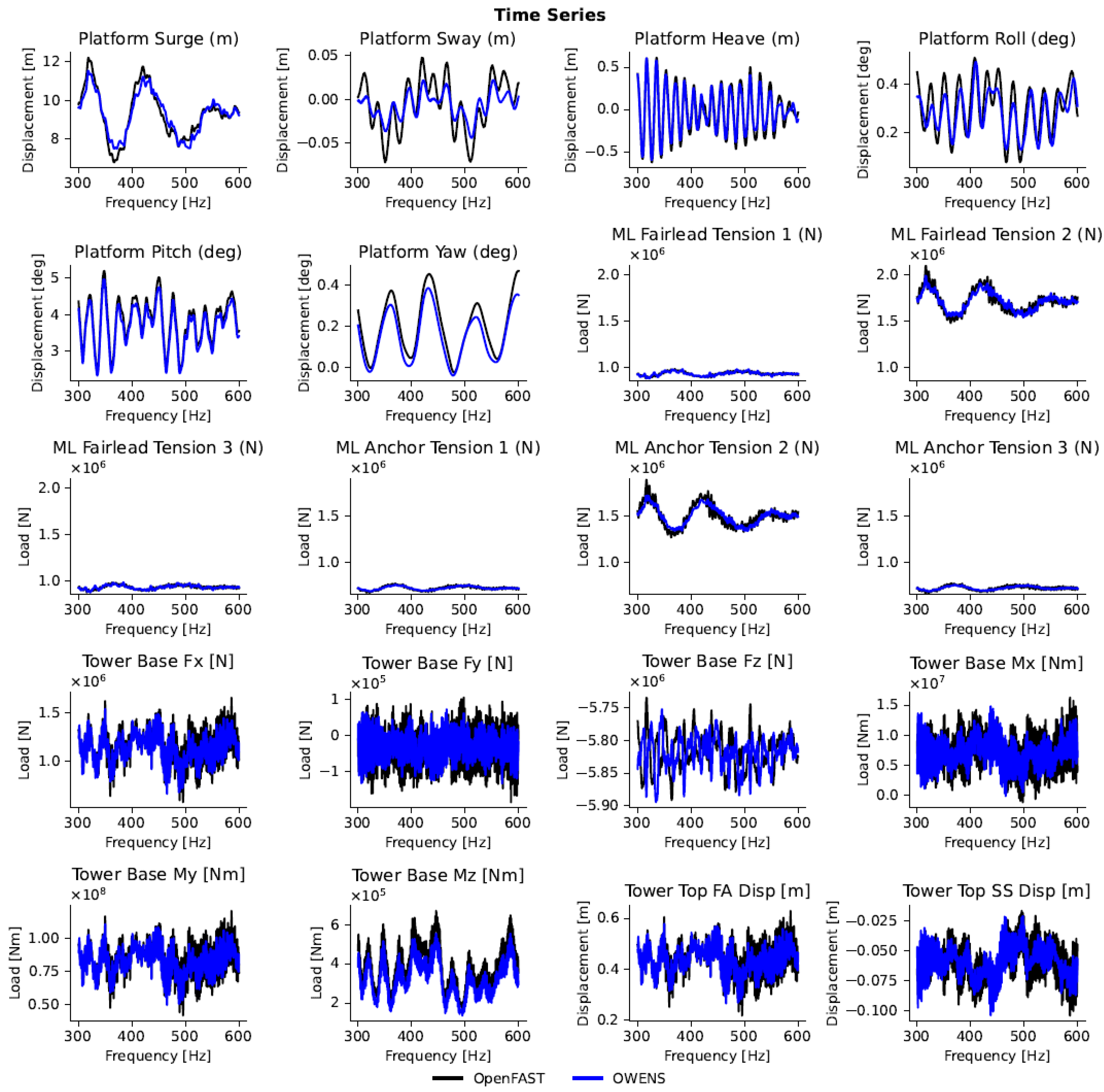
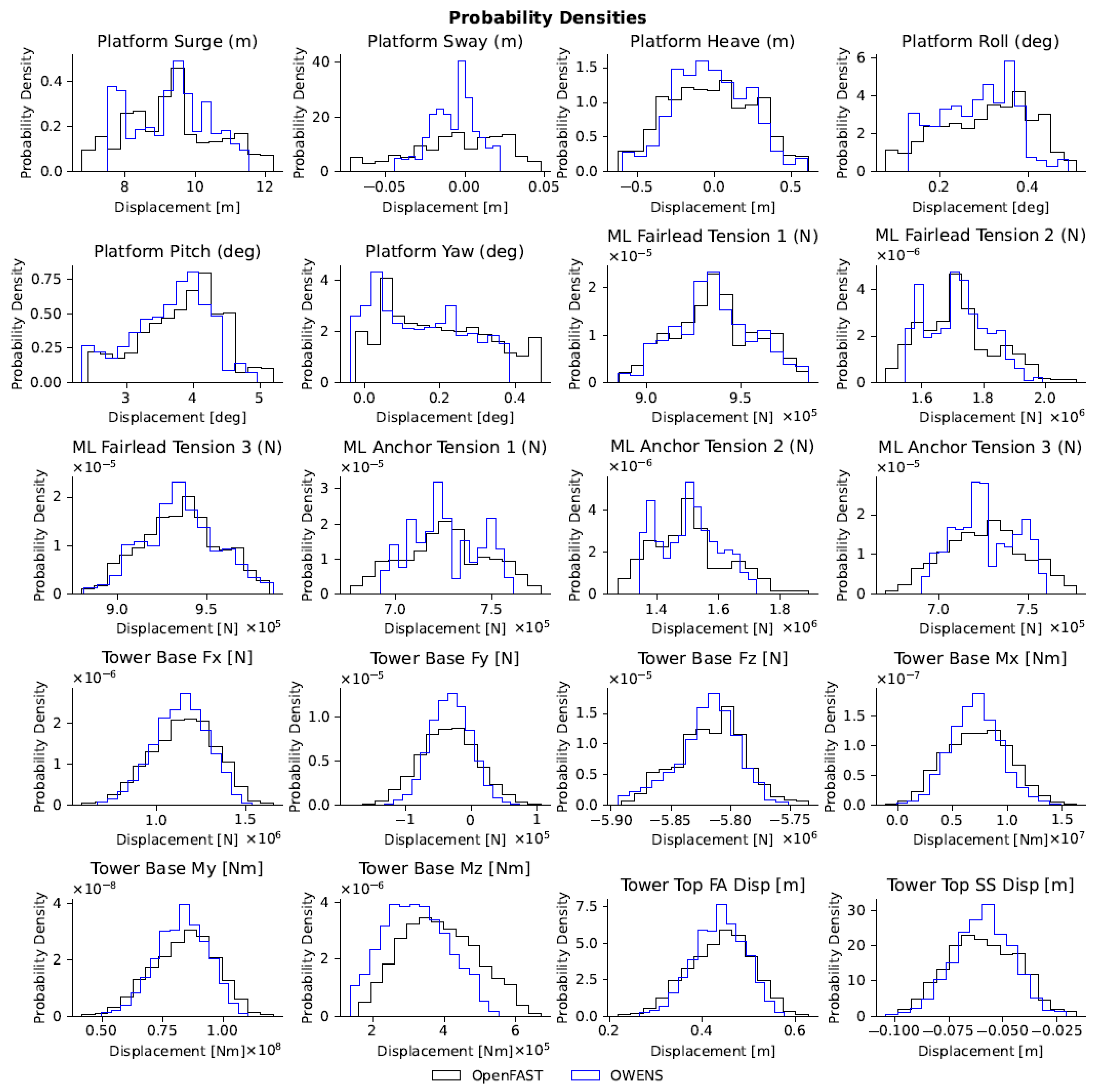
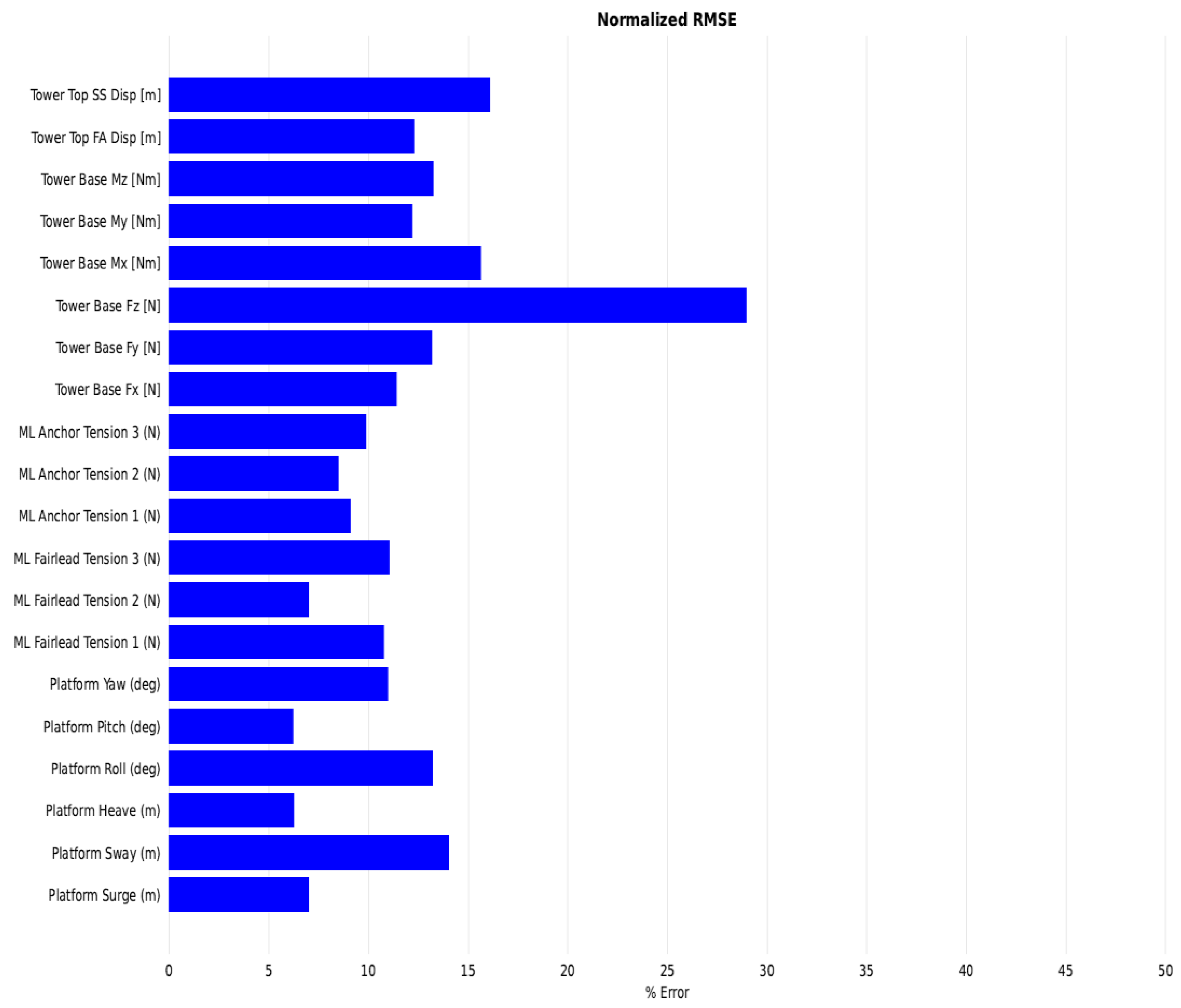
This work demonstrates a new hydro-elastic coupling methodology in OWENS to model floating offshore vertical-axis wind turbine systems with coupling to OpenFAST modules in the time domain. This builds upon other recent work validating the OWENS aerodynamic and aero-elastic coupling [
16,
17], and will allow OWENS to be applied to floating VAWT analysis in a better supported and more accessible manner. Results show good agreement between the coupled OWENS code and an equivalent OpenFAST simulation, with discrepancies in the tower base vertical loading and wave frequency mooring line response identified and to be corrected in an upcoming OWENS release to fully validate the code coupling. OWENS validation efforts will continue as capabilities of the code continue to expand and floating VAWT experimental data become available, enabling researchers and industry partners to model floating offshore VAWT designs more easily and accurately to reduce the levelized cost of energy and improve deployment.
The OpenFAST code changes described herein are publicly accessible through the OpenFAST GitHub repository and will be maintained as part of the OpenFAST code base. The new files may also be modified appropriately for utilizing other C-based languages with the OpenFAST Fortran modules. The Julia wrappers coupling the OpenFAST C binaries to OWENS are also publicly accessible via the OpenFASTWrappers.jl GitHub repository and will be maintained as OWENS continues development.
Immediate future work will focus on improving the accuracy of the coupled OWENS code by correcting the vertical tower node behavior and adding wave kinematics coupling for the mooring lines, as described in
Section 3.3. Further work will then primarily focus on continued OWENS validation. Extended validation for the floating functionality in severe environmental conditions is needed and will be subject to future code-to-code comparisons. Additionally, validation efforts for both land-based and floating capabilities in OWENS are being planned for newer VAWT experimental data as they become available.

 ,
, 


