
Blanket Cooling of a Fusion Reactor

Competence Center for Thermal Energy Storage (CCTES), Lucerne University of Applied Sciences and Arts, Technikumstrasse 21, 6048 Horw, Switzerland
*
Author to whom correspondence should be addressed.
Energies 2023, 16(4), 1890; https://doi.org/10.3390/en16041890
Submission received: 13 January 2023
/
Revised: 1 February 2023
/
Accepted: 10 February 2023
/
Published: 14 February 2023
(This article belongs to the Special Issue Volume II: Heat Transfer and Heat Recovery Systems)
Abstract
:Nuclear fusion is the gateway to a whole new paradigm of energy and is a strong candidate for the decarbonization of electricity generation on a global scale. With recent developments in high-temperature super-conducting magnets, the race is on to develop sub-systems which will support a commercially viable fusion reactor for use as a thermal power plant. The fusion of lighter elements creates an enormous amount of heat which must be transferred away from the reactor core. These intense conditions require novel approaches to efficiently transfer very high heat loads into useable thermal energy without compromising the structural integrity of the reactor core and the surrounding components. This report outlines the concept of a fundamental approach to solve the heat transfer problem as proposed by Commonwealth Fusion System’s design for a fusion reactor. A literature review was conducted for other applications that could serve as inspirations, as well as material properties and machining methods for the proposed power exhaust system. A dive into the theoretical thermodynamic and fluid dynamic characteristics of plate heat exchangers and finned surfaces was conducted from a fundamental perspective. A laminar flow regime was studied for the purpose of setting the floor for energy needed to pump coolant while simultaneously representing the least favorable heat transfer regime between a solid surface and a fluid. The results served as a basis for dimensioning and executing numerical simulations as a means for a first look into a solution of this heat transfer problem. The results were compared with the theoretical conclusions and judged based on constraints of the system. Recommendations were made for the continued development of a corresponding system.
1. Introduction
Energy from the nuclear fusion of two lighter elements represents the next paradigm in energy generation. It represents the most common type of observable reaction in the universe, the enormous amount of energy released by stars, and the incredible potential it could provide to humanity [1,2,3]. These intense reactions create extremely high specific heat fluxes. The Competency Center Thermal Energy Storage (CCTES) is conducting a study based on principle ideas created by Commonwealth Fusion Systems (CFS) to develop a concept for a part of the power exhaust system (PEXS) necessary for the removal of heat from a fusion reactor core. In a former CFS publication, the basic engineering principles for a blanket cooling system within an affordable compact robust (ARC) reactor were described. However, a design proposal for heat exchange surfaces and heat transfer fluid has not been published yet [4]. A reactor core consists of fusion fuels reacting in a magnetically confined vacuum vessel, requiring cooling. Vacuum vessel heat flux density reaches a peak of 12 MW/m2, which needs to be removed via FLiBe (Fluoride–Lithium–Beryllium) molten (liquid) salt to maintain material integrity. The intention of this work is to suggest and examine one potential solution approach: a novel design proposal for removing high-end vacuum vessel heat fluxes using a FLiBe molten salt heat transfer fluid. The design proposal is based on data from CFS and former research work at CCTES. The design proposal includes the incorporation of manufacturing possibilities and a general design to keep the inner (thin) shell mechanically stable, to allow for high heat transfer coefficients by forced convection (or even free convection), and for mass transfer exchange with the molten salt reservoir (for the transport of the heat to the bulk FLiBe tank). A general layout of the design is developed, general assumptions of the required flow rates of FLiBe and a possible way to evenly distribute this over all 300 m2 of the blanket surface are shown, the blanket surface is structured with a grid consisting of fins, and a detailed numerical calculation of the local heat transfer under such conditions is executed. Starting with a parameter study of the influence channel dimensions and fin width, the general feasibility in terms of heat transfer and pressure drop for FLiBe and laminar flow is examined.
2. Materials, Theory, and Methods
2.1. Materials
Three main materials are needed to construct a heat exchanger or PEXS. Tungsten (W, Wolfram) is the proposed material for the plasma-facing surface responsible for transferring heat to the molten FLiBe salt in the ARC reactor design. It has a high melting temperature of 3400 °C, low vapor pressure, and high tensile strength [5,6]. Tungsten is the material of choice in several divertor designs, including an ITER (International Thermonuclear Experimental Reactor), for its high thermal conductivity (kW ~175 W/(m·K)), high temperature operating range (~1500 K), and resistance to plasma erosion [4,7,8]. It is proposed to use a plasma-facing layer that is as thin as possible to minimize thermal resistance while maintaining structural integrity during the operating life cycle.
Above the Tungsten layer is the fluid responsible for capturing and removing heat from the plasma-facing surface. The fluid proposed by the CFS paper [4] is FLiBe (LiF—BeF2; 66 mol%, 34 mol%). FLiBe has several engineering advantages for use as a coolant in a magnetically confined plasma fusion reactor. It exhibits a favorable operating temperature range between 800 and 875 K, performs well as a radiation shield, and has favorable flow characteristics [9,10,11]. For the proposed FLiBe operating temperature (800~875 K), the dynamic viscosity of FLiBe is approximately 10 times higher than water at room temperature (293 K). Table 1 outlines the recommended values for FLiBe over a liquid temperature range between melting (732 K) and boiling (1703 K) points.
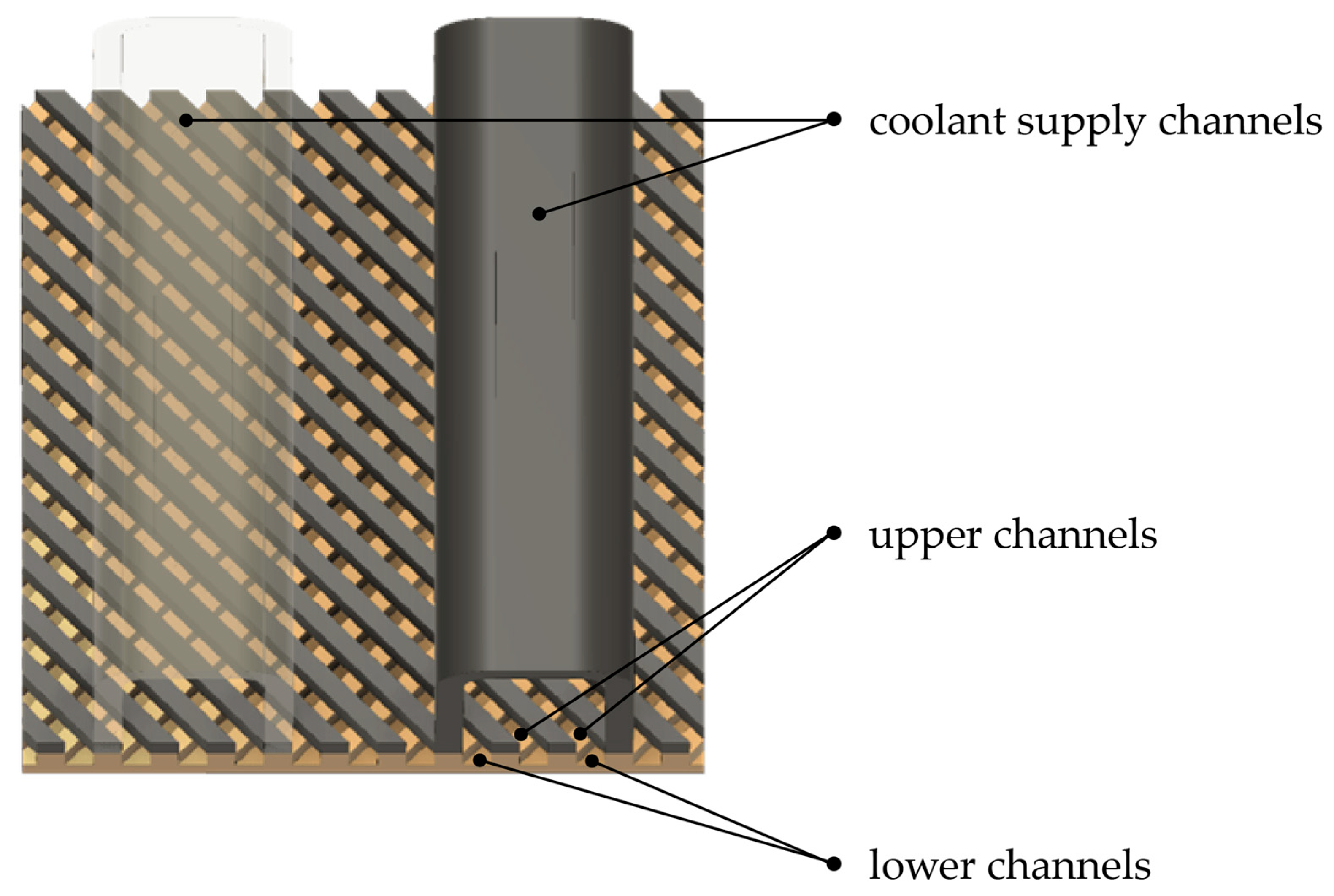
The design proposed in this paper was a super-structure of Inconel 718 tasked with distributing FLiBe to the tungsten layer and providing structural support to the “cool” side of the PEXS. It operates at a lower temperature than plasma-facing surfaces and provides a structural level of support to the inner tungsten layer. Inconel was chosen for its high melting temperature (~1480–1610 K), very high yield and tensile strength, and excellent weldability with itself and tungsten [14,15,16]. Figure 1 below illustrates the conceptual design of the channeled tungsten plasma-facing surface (orange in the back) attached to a second set of Inconel 718 channels (dark gray). FLiBe capillary channels are shown over the top of the entire construction.
2.2. Theory
A full understanding of heat transfer and the effects of material extended away from a surface is requisite to properly evaluating designs which best conform to boundary conditions. Table 2 below shows the boundary conditions of the PEXS which must not be exceeded. This set of boundary conditions is considered nominal operating conditions, as outlined by CFS.
2.2.1. Heat Transfer
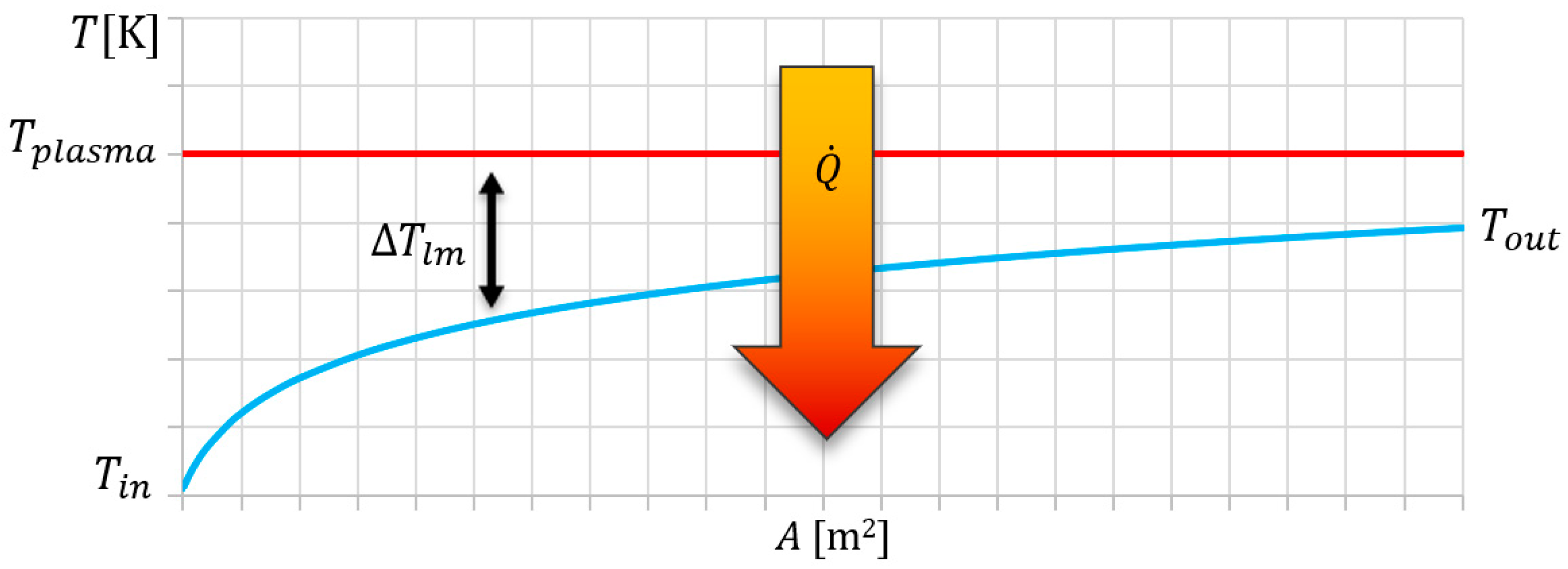
Heat from the inner core to the tungsten shell is transferred mainly by radiation. The following theory assumes the maximum tungsten temperature will be maintained by an equilibrium of radiation from the core to tungsten and convective heat transfer from tungsten to FLiBe. The boundary conditions were conceptualized in terms of heat transfer using the general theory for plate heat exchangers. Figure 2 below qualitatively shows the evolution of the FLiBe temperature as it passes through the tungsten structure. It is governed by the following equation:
is the heat flux in watts, is the FLiBe mass flow in kg/s, is the specific heat capacity J/(kg·K), is the overall heat transfer coefficient W/(m2·K), and is the area of the plasma-facing surface. is the logarithmic mean temperature difference (LMTD) between the heat source and heat sink. It is defined in Equation (2) below and accounts for a non-uniform temperature difference along the path of the fluid. is the temperature of the tungsten shell on the inner plasma-facing side.
Equation (1) can be rearranged to give us the minimum required heat transfer coefficient and minimum area-specific FLiBe mass flow , as shown in Equations (3) and (4), respectively.
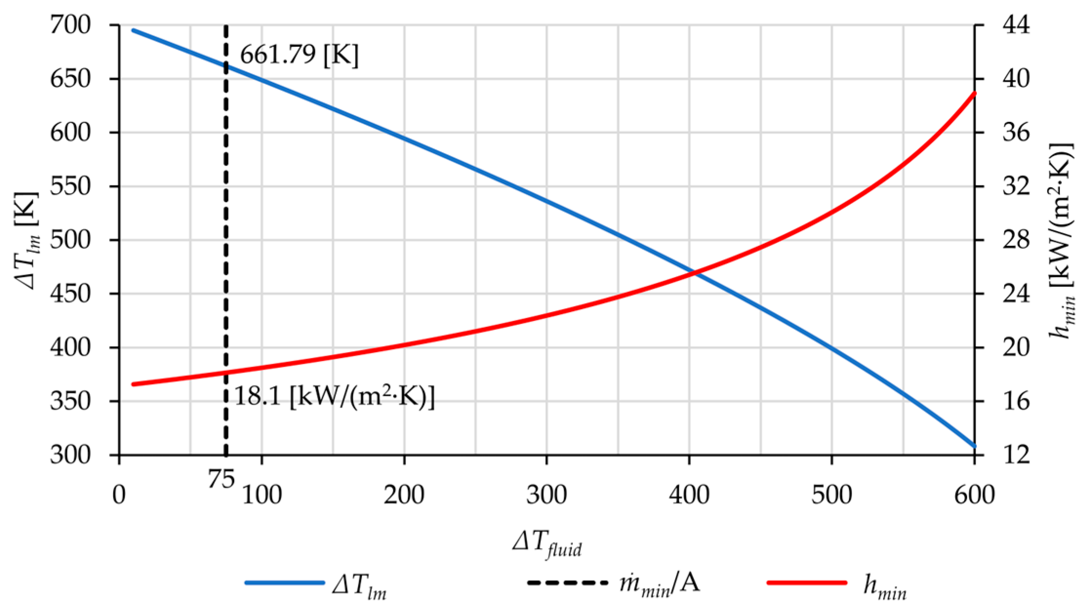
Using Equations (2)–(4), and the boundary conditions in Table 2, a ~660 K, ~18 kW/(m2·K), and a of ~68 kg/(m2·s) were found. These calculated quantities represent the heat flow characteristics to remain within the boundary conditions set forth by the ARC reactor design. Figure 3 below shows the proposed ARC reactor operating point in terms of fluid temperature change, LMTD, and . This helps to maximize the thermal driving force, keep plasma facing surfaces cooler than the maximum temperatures allowed, and minimize asymmetric thermal stresses across the tungsten elements.
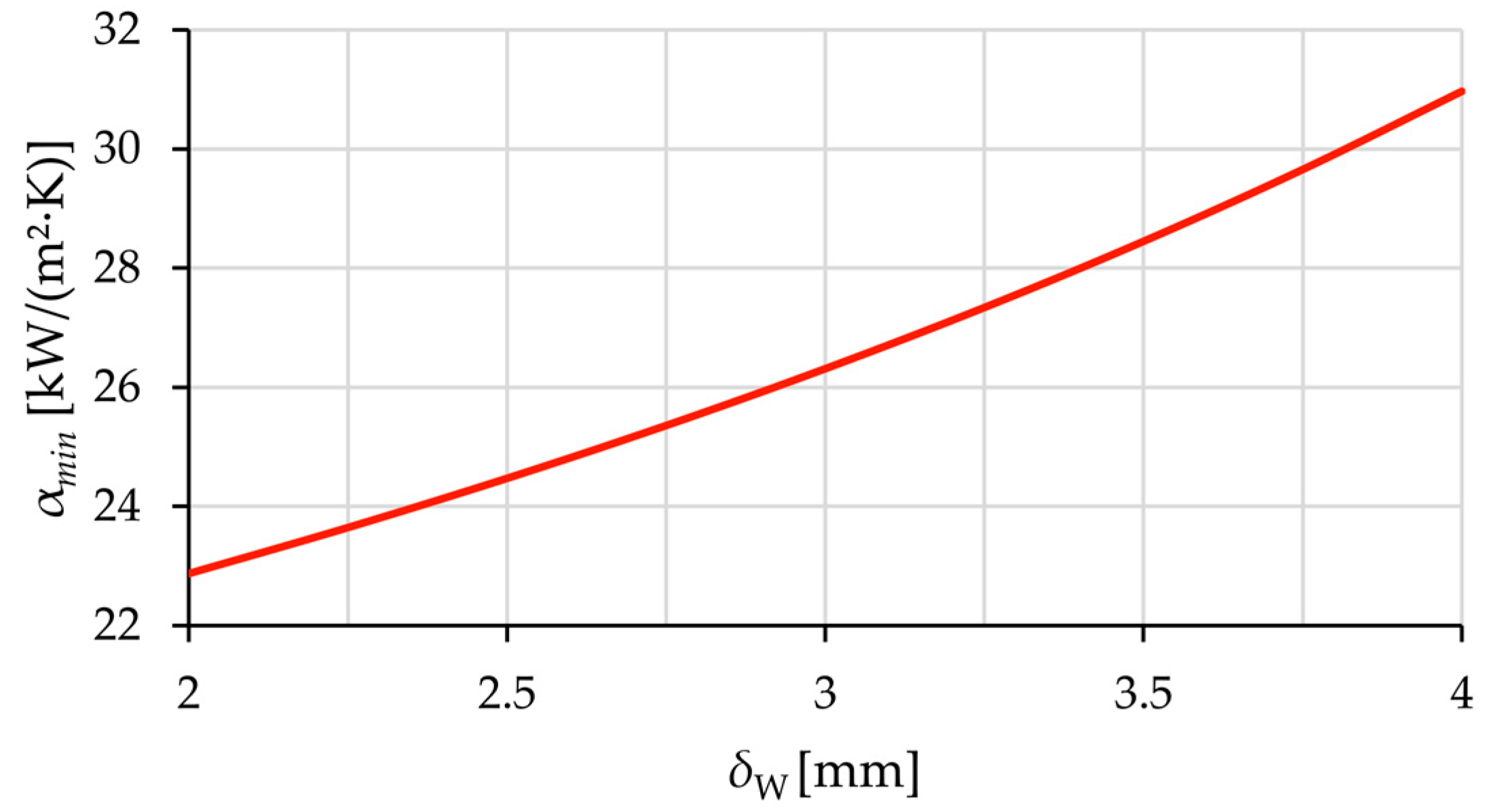
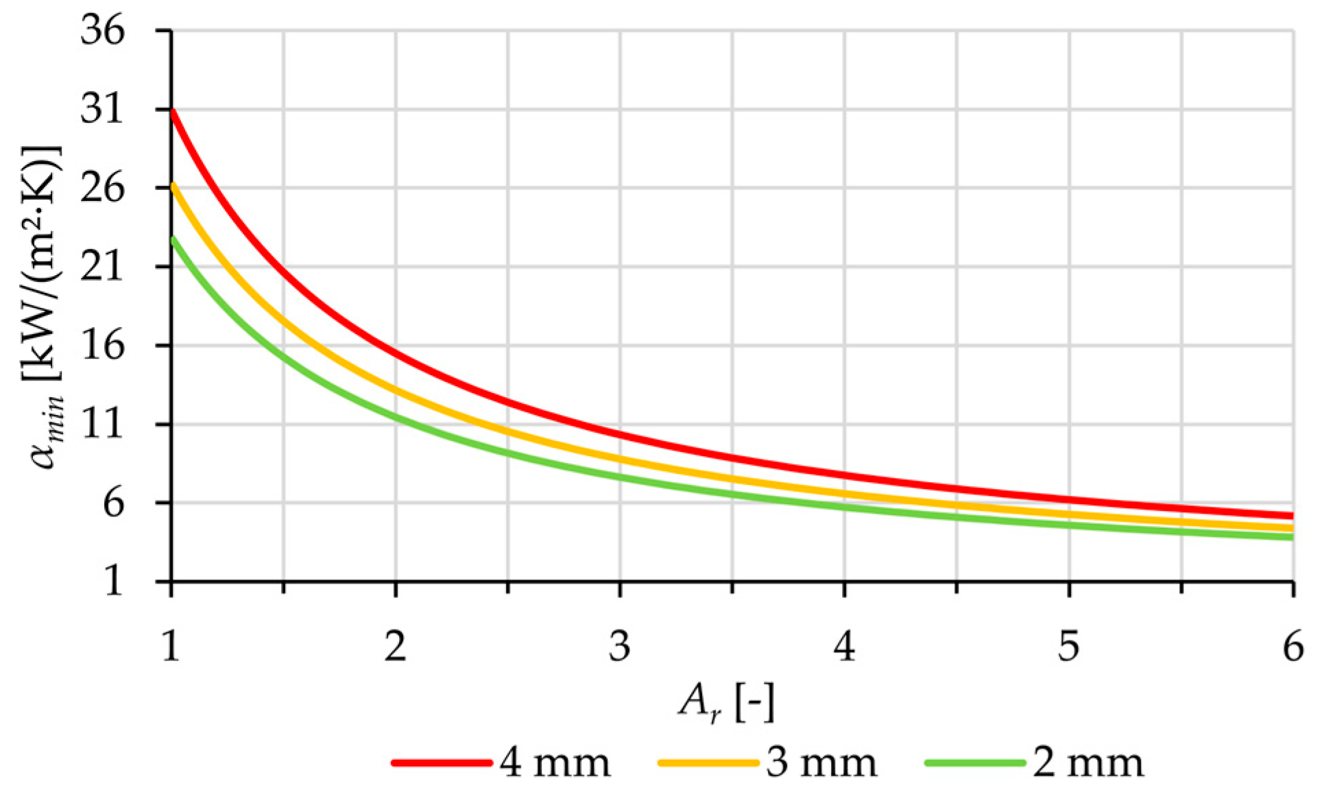
The minimum required overall heat transfer coefficient is a function of tungsten thickness and the minimum average heat transfer coefficient for the fluid surface . Equation (5) below defines in terms of these new quantities and is plotted against tungsten layer thickness in Figure 4.
2.2.2. Area Ratio
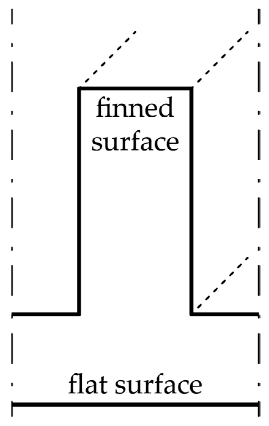
Geometric features added to a surface increase the surface area and direct fluid flow in an advantageous manner. These geometric features take the form of extended elements, “fins”, which extend away from the plate. The additional area is an advantage as the required decreases as the total area of the finned surface increases relative to the flat plate area . The area ratio is defined as and can be used to adjust the required as a guide for design. Figure 5 below shows the general concept of increasing the area of a surface with a rectangular fin relative to a non-finned surface.
Figure 6 below shows the change in with an increasing area ratio . Theoretical thermal performance was analyzed to calculate the effects of different thicknesses of tungsten for the vacuum vessel. It was found that by reducing the thickness of the tungsten to 2 mm and increasing the area ratio significantly reduced . Figure 6 below shows the effect of reducing the thickness of the tungsten layer and increasing the area ratio using Equation (5).
The higher the area ratio, the better the chance a design has at successfully meeting the task of transferring the required amount of heat. However, there are limiting factors which constrain the geometry of the fluid surface to a range which is achievable. The assessment of the proposed design used a tungsten plate of 2 mm in thickness and an area ratio >2. This represented the minimum vacuum vessel wall thickness and a minimum in thermal resistance to test the thermal performance of the design concept. A thermodynamic design point of an ~12,000 [W/(m2·K)] was considered in the scope of this study as it is typical of forced convection for non-metallic, single-phase liquids [17].
2.2.3. Fin and Surface Efficiency
The use of fins on a surface constitutes the use of more material above the plate itself. The added material incurs thermal resistance to heat flow and thus factors in when determining optimal fin geometry. The use of very long fins is not required to reach the optimal heat transfer rate [18]. Fin efficiency is a term which describes the ability to transfer the heat of a flat surface or a tube with fins relative to the same surface without fins. It is the ratio of the average temperature difference between the end of geometry extending away from the base and the fluid to the average temperature difference between the base of the surface and the fluid [17]. Equation (6) below summarizes this definition.
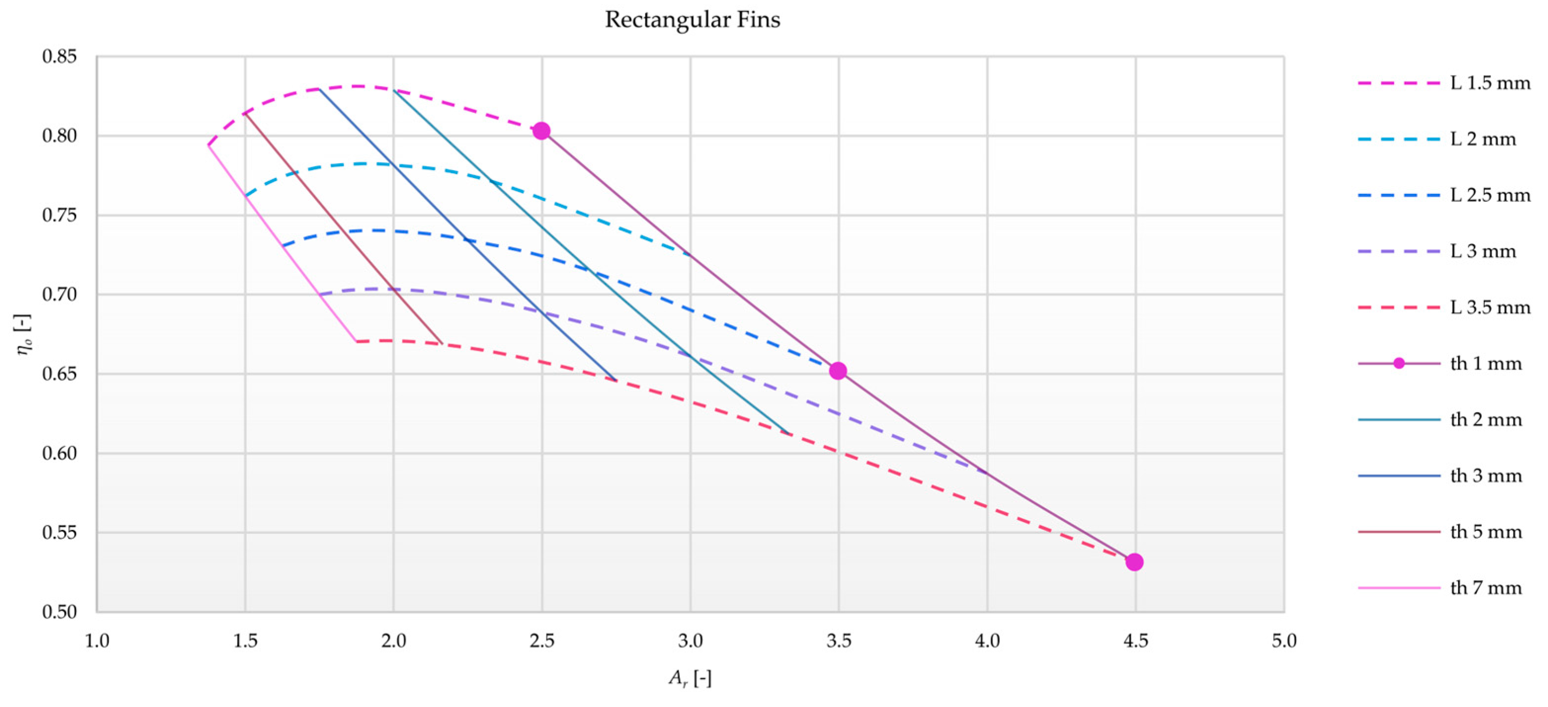
The efficiency of the fins can be further expanded into an overall surface efficiency . The overall performance of a finned plate is a function of the fin efficiency , the number of fins , the area of each fin , the total area of the finned plate , and . Equation (7) below is the overall efficiency of a finned plate flat plate.
The surface efficiency of rectangular fins is plotted below in Figure 7 for an area of 1 m2 against , fin thickness , fin length , and a channel width of 1 mm.
The primary purpose of optimizing fin geometry is to maximize thermal performance using the least amount of material, while the secondary purpose is to promote the mixing of cool fluid down to the surface of the finned structure. Rectangular fins were chosen as the best solution, as their shape allows for the optimal addition of surface area with vertical walls. The five other finned surfaces considered (rectangular pins, triangular/parabolic fins, and pins) exhibited poorer overall fin efficiencies with the same area ratios.
The fluid surface geometry is of critical importance to design a structure capable of handling the proposed high heat flux density of the ARC divertor leg. An increased area ratio was achieved by extending material away from the plate surface in the form of rectangular fins, as shown in Figure 5 and Figure 7. A logical starting point for analysis was using a narrow fin thickness (1 mm), narrow fluid channels (1 mm), and tall fins. Table 3 below shows the dimensions and their corresponding overall fin efficiencies, area ratios, and hydraulic diameters .
2.2.4. Pumping Power
About 300 m2 is needed to envelop an ARC vacuum vessel [4]. Using the calculated area specific mass flow rate , ~20,400 kg/s is required to provide the required amount of FLiBe to cool the vacuum vessel shell under the proposed conditions. The minimization of energy use by auxiliary systems to circulate a coolant is a priority. The pumping power required has the potential to demand a significant proportion of generated electricity and must be kept to a minimum. Equation (8) below shows the hydrodynamic relationship between pressure loss, fluid mass flow, and electrical power needed to move a fluid with pump efficiency.
2.3. Methods
The boundary conditions relevant for this study were the heat densities to be transferred to the FLiBe heat transfer fluid. The design had to be built to minimize fluid pressure losses and thus minimize energy consumption for cooling. Furthermore, uniform temperature gradients within the PEXS material were crucial to maintaining symmetric thermal stresses and material longevity.
A literature review was performed to find any high-power heat transfer applications either in commercial use or tested in a lab. The results of the literature review served as a basis of inspiration for the initial designs tested in a numerical setting using COMSOL 6.0 [20]. Laminar flow conditions were analyzed as they represent flow conditions which exhibit the lowest pressure losses and worst (in terms of low) heat transfer conditions. This provided a safe-sided starting point in evaluating the feasibility of certain designs with regard to the boundary conditions.
3. Results and Discussion
The results are presented in the following manner: the state of the art, design concept, and simulated output. Each section provides the design development chronologically, and therefore, the result of each section is built upon the previous result and presented as such. A short discussion of each step is included with the results.
3.1. State of the Art
A literature review was conducted to discover commercial and/or research applications which could serve as a starting point for a design concept. Microchips and integrated circuits have evolved to reach 2.25 MW/m² by employing one of the four types of heat transfer: radiation and free convection, forced air-cooling, forced liquid-cooling, and liquid evaporation [21]. Another study examined the thermal exhaust requirements for VLSI (very-large-scale-integrated) circuits [22]. Using a micro-channel structure, laminar flow regime, and employing water as the heat transfer fluid, a heat flux of up to 7.9 MW/m2 was achieved with a maximum temperature change of 71 K between substrate and inlet fluid temperature [21]. In this paper, it is further suggested a heat flux density of 10 MW/m2 is possible by scaling a liquid-cooled heat exchanger design to microscopic dimensions. Table 5 below shows the experimental results for several dimensions, fluid pressures , flow rates and heat flux densities . Note specific mass flow rates for water as a coolant, , were calculated from available data and are of the same order of magnitude as the specific mass flow rates calculated using FLiBe.
A review of heat sinks related to nuclear fission reactors was investigated for a possible corollary for a solution to this heat transfer problem [23]. Nuclear reactors designed to generate electricity exhibit high rates of heat transfer from fuel rods to coolant fluid. Various coolants are used depending on the reactor design. An overview is given in Table 6 below to outline potentially suitable solutions.
Coolants are put under forced convection flow regimes to maximize heat transfer and safety during operation. In addition, some designs allow for a phase change of the coolant to increase heat transfer rates.
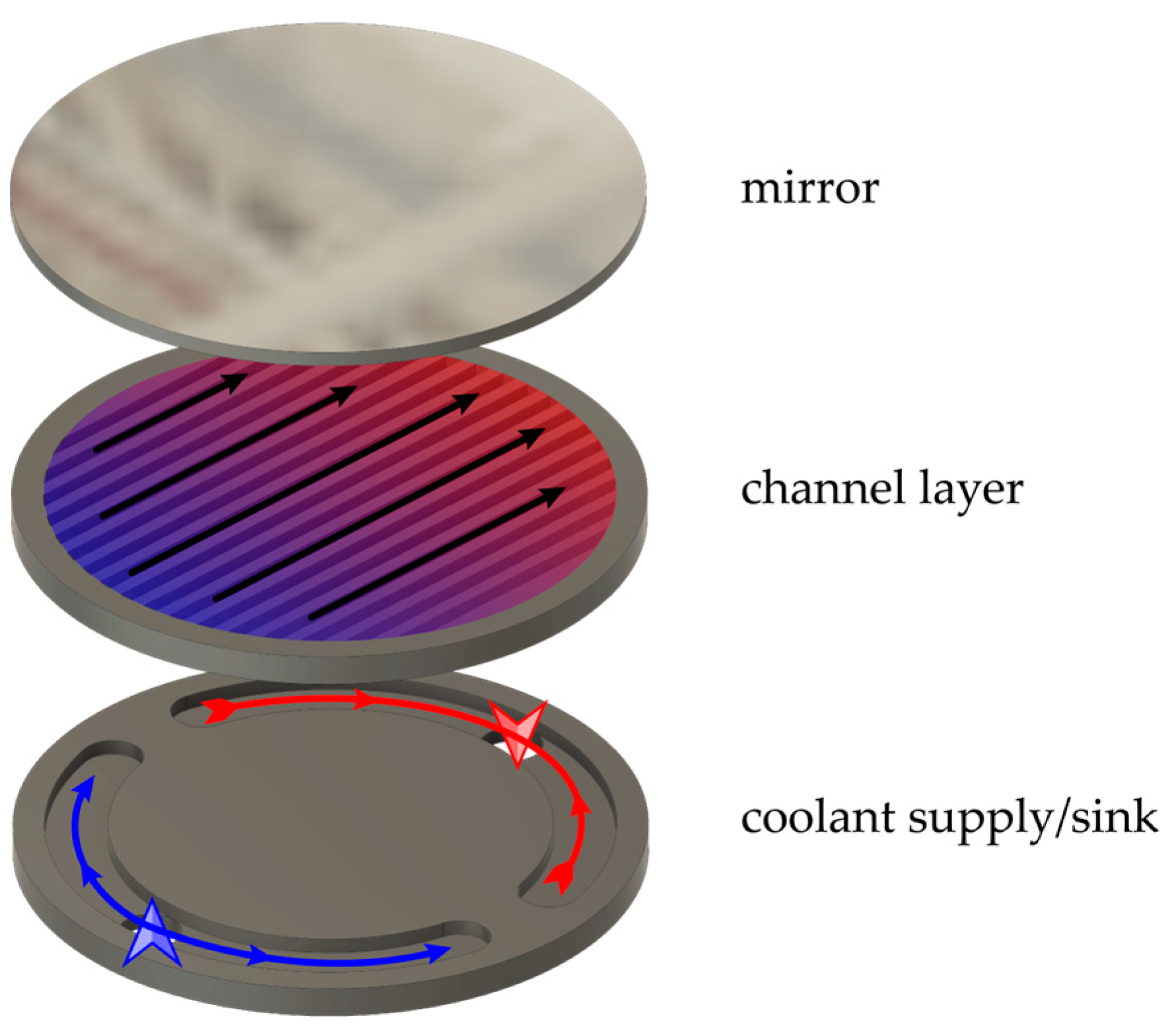
Mirrors used for the concentration of high-power laser light experience significant heating. Light beam quality experiences a sharp decline when the mirror begins to distort due to heating [24,25]. To mitigate these negative thermal effects, active cooling of the mirror with water is applied. Table 7 below outlines the assumptions made for a simulation regarding the heat transfer area facing the fluid, and Figure 8 shows the proposed design. It was found that a microchannel heat sink was able to decrease the thermal deformation of a mirror. Similar to the VLSI circuit heat sink, microchannels were found to have a high depth to width ratio.
Another high-power heat sink application was designed to limit the temperature rise used in HVDC (high-voltage direct-current) thyristors in electrical grids. The heat flux associated with the use of this equipment could experience 2 MW/m2 under the condition of a very low acceptable temperature increase. The design of the heat transfer surface in this application is also of interest to us. Figure 9 below shows a double-layer cross-flow matrix of channels that is used to move heat away from the contact surface and limit the temperature rise in a thyristor [26].
This design proposes a second example of using small channels near the surface for the purpose of efficiently moving large amounts of heat away from the surface needing to be cooled.
3.2. Design Approach
The results of the literature review gave a deeper insight into the general design characteristic of high-power heat exchangers tasked with cooling a surface or device. Three of the four designs studied employ the use of small channels to guide a coolant near a surface to remove heat. In combination with the required geometry of the proposed ARC reactor design, the following concept was developed followed by an evaluation with numerical simulation.
3.2.1. Proposed ARC PEXS Design
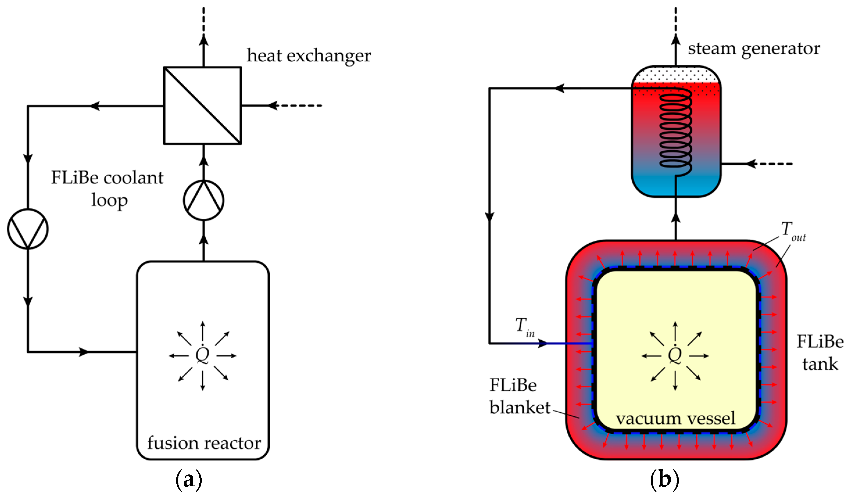
The proposed design provided from the literature was used as a starting point for the ARC PEXS [4]. Theoretical principles and designs from other high-power heat exchange applications were used to develop a concept for a PEX capable of transferring heat away from the vacuum vessel per the stated boundary conditions. Figure 10 below shows a simplified schematic (a) and illustration (b) of how heat is removed from the fusion reactor.
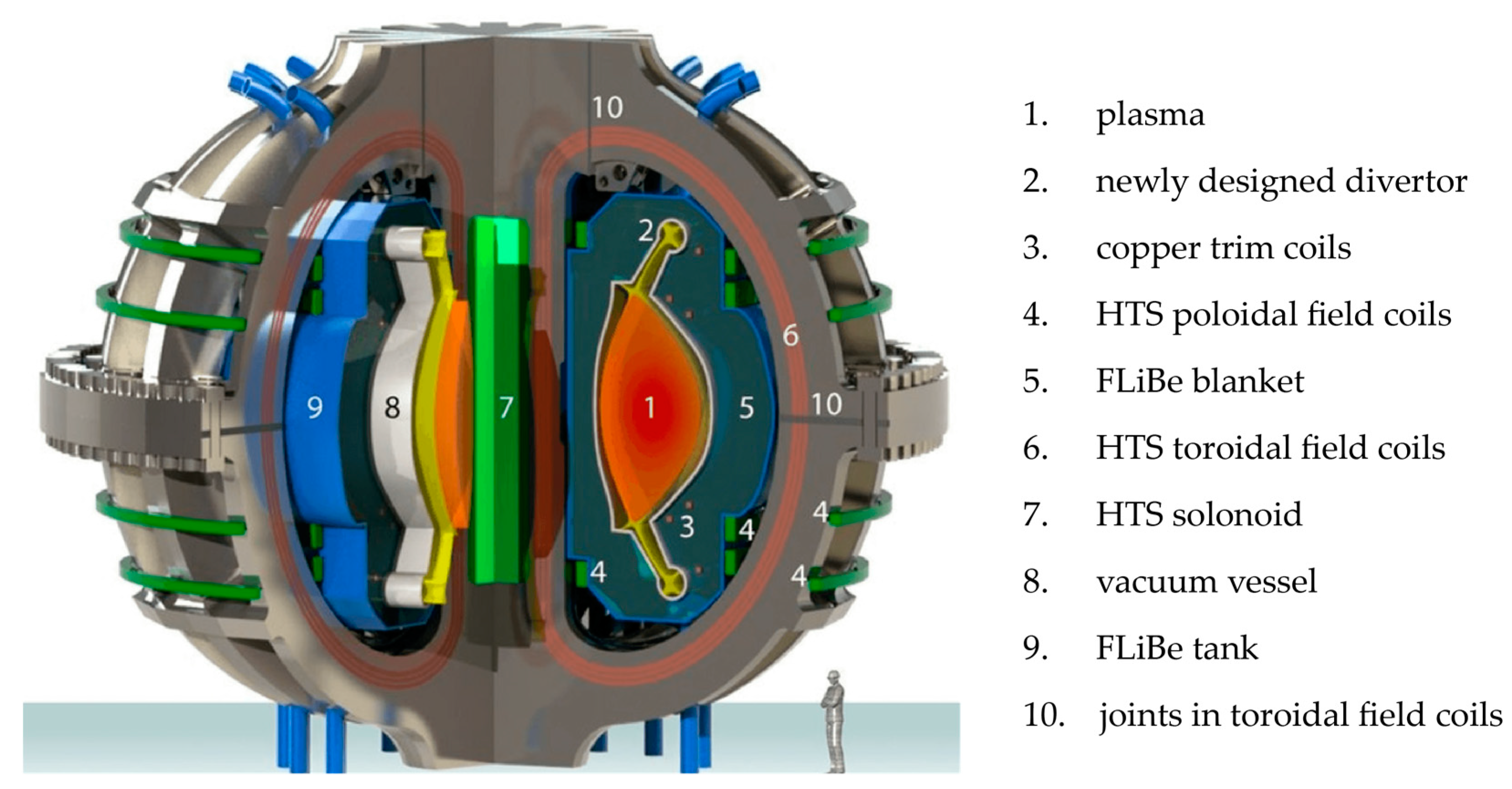
FLiBe is circulated over the surface of the fusion reactor (vacuum vessel) to remove heat from the core and transfer heat to a secondary loop (a). Coolant is pumped from the point labeled and distributed evenly over the surface of the vacuum vessel (dark blue/black dashed line). It removes heat from the reactor core and maintains operating temperatures below 1500 K on the plasma-facing side of the tungsten shell. The heated coolant is discharged locally (red arrows) into the FLiBe tank, which encloses the vacuum vessel. The heated FLiBe is taken from the tank to generate steam for electricity generation (b). The ARC reactor components relevant to this study are the divertor leg (2), FLiBe blanket (5), and vacuum vessel (8), shown in Figure 11 below.
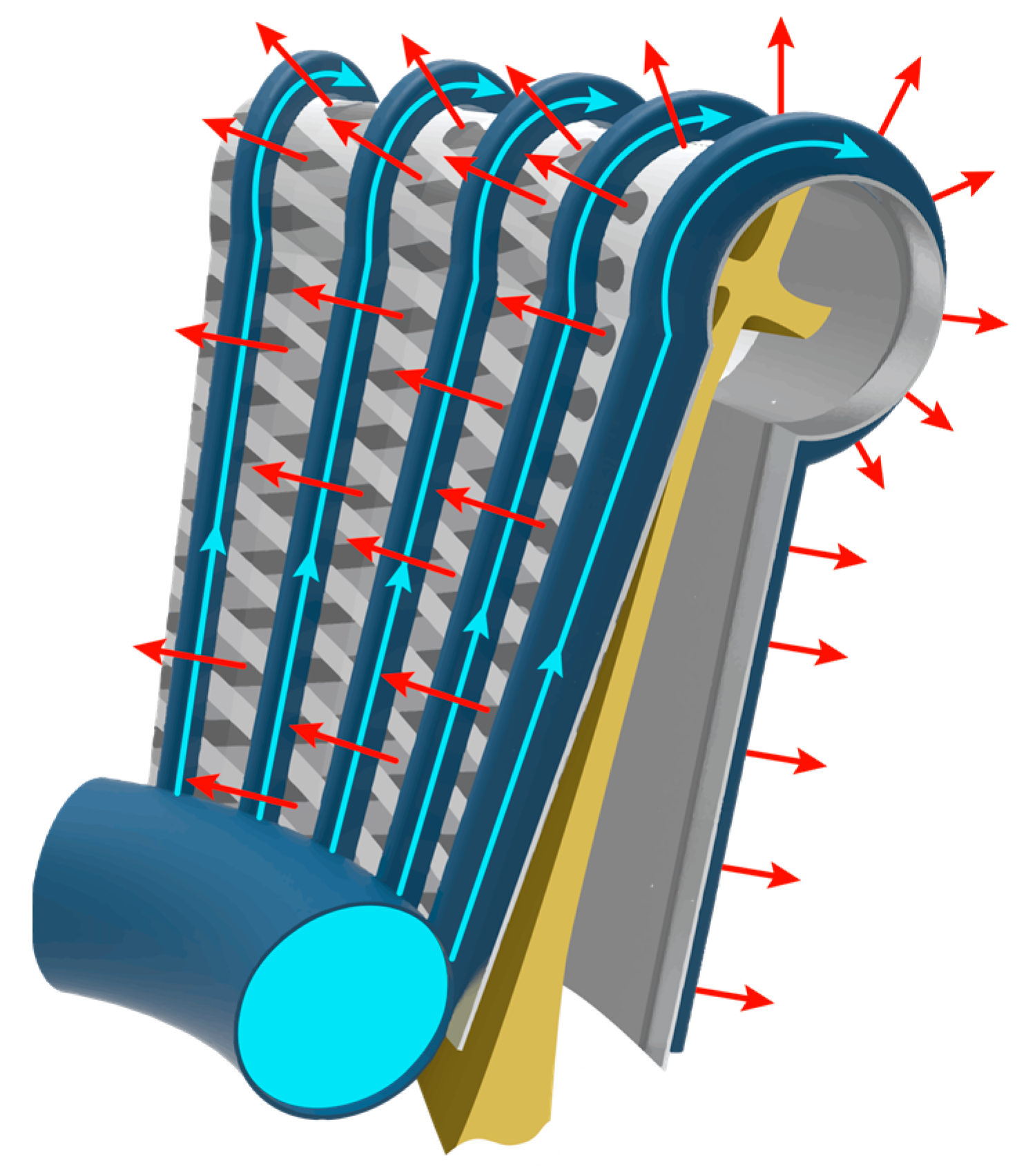
A network of channels supplying coolant to the surface of the vacuum vessel is essential to maintain its structural integrity. Multiple inlets would be necessary to maintain a low temperature change in the coolant while reducing the pressure drop between pump and outlet to the FLiBe blanket. Figure 12 below shows a concept for cooling the divertor leg via a primary supply channel (circular blue pipe) branching into secondary capillary channels (blue longitudinal conduits) before entering a series of finned structures (gray lattice layer) attached to the vacuum vessel.
3.2.2. Fluid surface
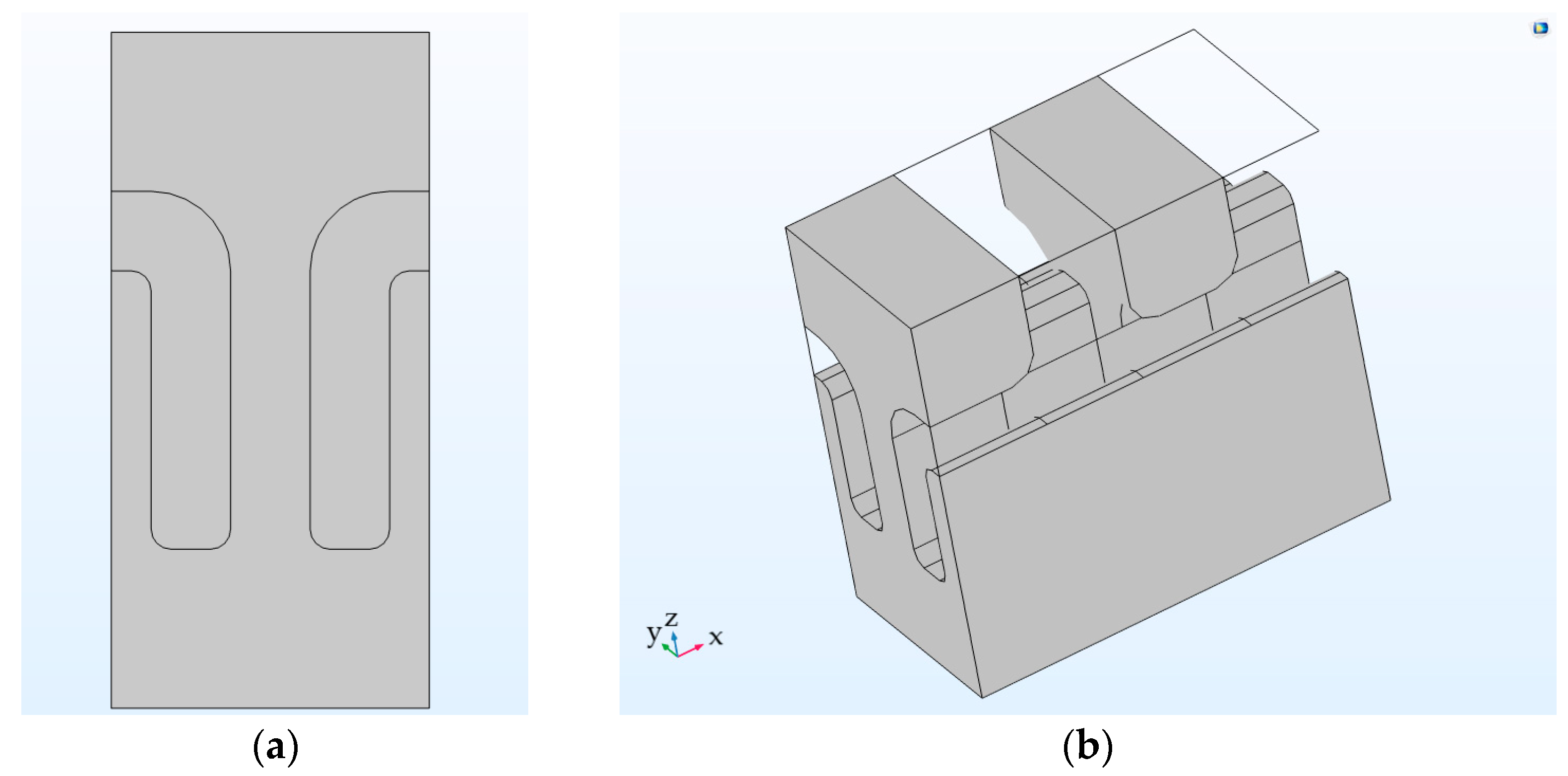
The construction assumed each fin is attached to an upper cross-fin, as shown in Figure 1, at a 90° angle, contrary to the geometry in Figure 1. This was chosen to simplify manufacturing and assembly. Consequently, it presented an undesired thermal bridge to the upper channels. Thermal bridging was limited by attaching every other lower-channel fin with an upper-channel fin, resulting in a “∩-type” of lower-channel geometry. Figure 13 below shows a cross-section (a) and perspective (b) of the ∩-type lower channel.
3.3. Numerical Simulation
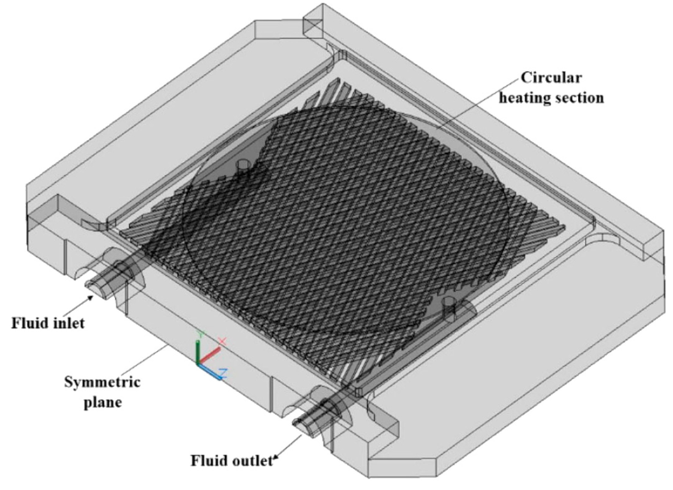
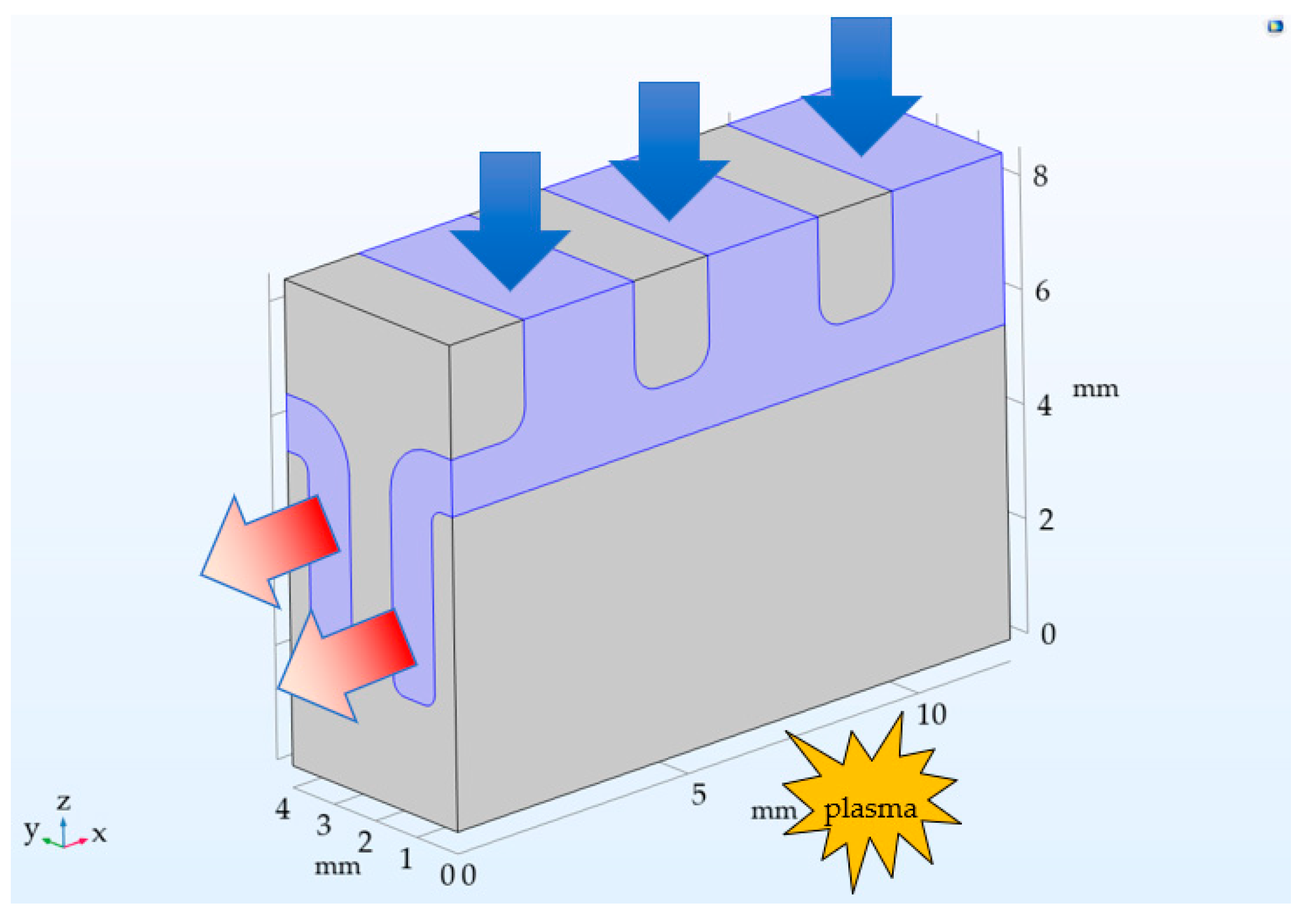
The construction shown in Figure 14 was chosen to take advantage of symmetry planes along the xz-planar vertical faces and the right-hand yz-planar vertical face. Figure 14 shows the fluid flow regime as simulated for all cases outlined in Table 3.
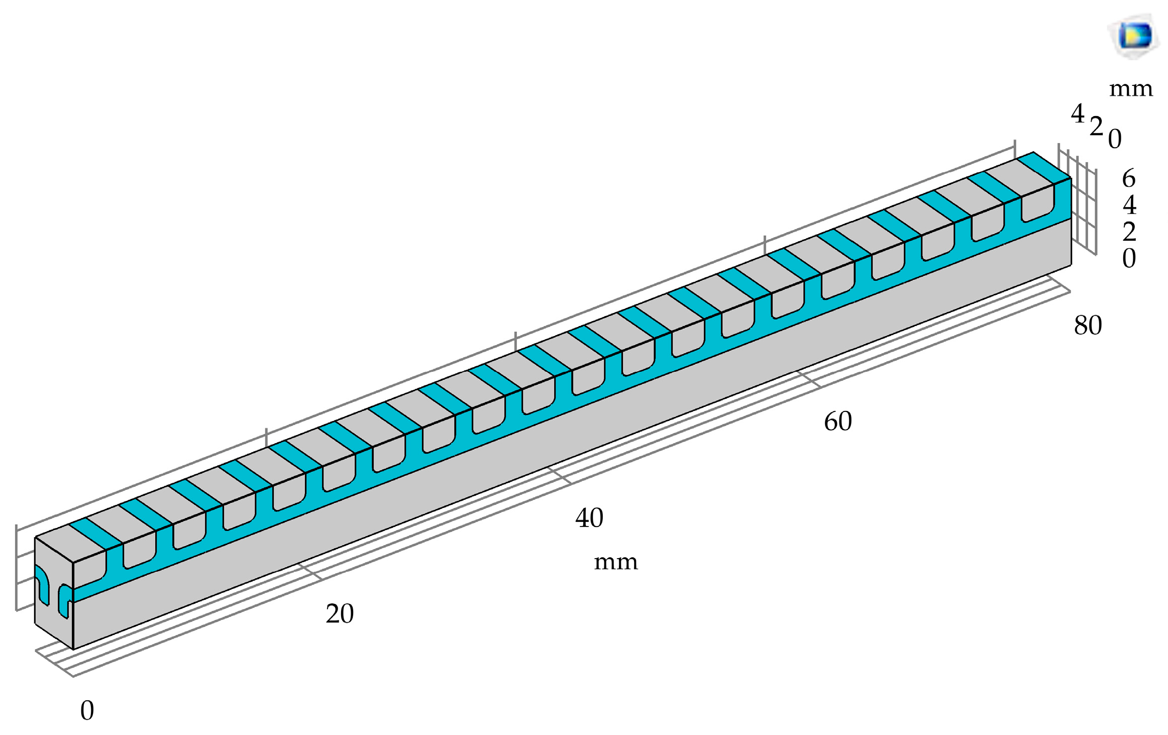
Inlets are defined by blue arrows and the outlets by red. Heat from the fusion reaction is applied on the bottom side and enters the fluid stream along the various surfaces of the channels. The illustration above is a rendering of the design concept with three channels in the simulated environment. Geometries with 1, 2, 3, 4, 5, 10, and 20 inlets for each fin length were analyzed for a total of 18 unique assessments. Figure 15 below shows a 20-inlet geometry.
Each combination of parameters was using a mass flow rate consistent with the area-specific mass flow rate calculated in Section 2.2.1.
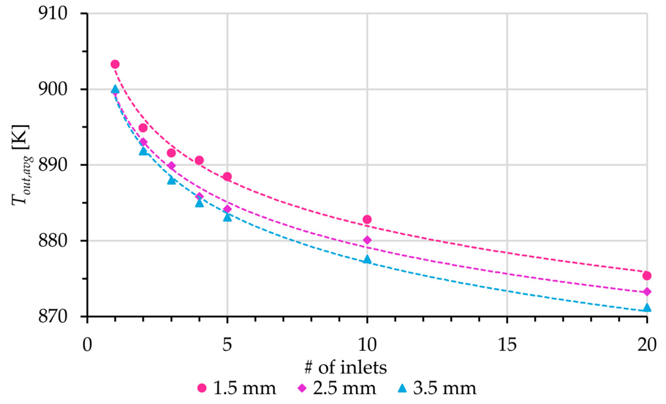
The thermal performance was first assessed by analyzing the average outlet temperature of each configuration. Figure 16 below shows calculated average outlet temperatures for each fin length (1.5, 2.5, and 3.5 mm) shown in the legend.
Each successive addition of inlets showed a reduction in the average fluid temperature at the outlet. This was expected as the addition of inlets introduced more FLiBe to a channel with fixed cross-sectional areas. The maximum fluid velocity increased with the number of inlets while decreasing with fin length for geometries with the same number of inlets. The maximum domain temperature, , and average heat transfer coefficient on the fluid surface, , also decreased with the addition of inlets up to three to four inlets before increasing again. The maximum pressure-drop from inlet to outlet across each geometry, , increased with increasing . Table 8 below shows the trends observed organized by fin length, area ratio, and average minimum heat transfer coefficient, , for each geometry by the number of inlets .
The simulated results indicate a thermal performance satisfying the boundary conditions for geometries with one to five inlets based on . The minimum average heat transfer coefficient for a 2 mm thick tungsten wall and flat plate ( was not consistent with the maximum temperature results. Simulated geometries included thermal bridges and a cool side boundary condition not considered in the theoretical analysis. Errors associated with the model, the use of average domain values for calculations (e.g., average outlet temperature), and deviations from theory explained simulations where exceeded 1500 K while exceeded .
4. Conclusions
The results of this study have determined there is a viable path forward to develop a PEXS capable of fulfilling the thermodynamic constraints of the ARC reactor design. Theories regarding heat transfer, fin and surface efficiency, and fluid dynamics were used as design guides for the development of a concept analyzed using numerical simulation. The analysis of the concept performance indicated positive progress in developing a heat exchange surface capable of transferring a specific heat flux of 12 MW/m². Simulated heat transfer coefficients for the fluid surface approached values found using an energy balance for heat exchangers. The most feasible solution was a channeled block of tungsten with fins of 3.5 mm in height, fin and channel widths of 1 mm, and five sequential inlets. It represented the solution with the lowest pressure losses and thus only consumed 2.3% of the produced electrical power generated. However, the simulated results were not fully in agreement with the theory. Further investigation is necessary into the accuracy of the model by means of empirical results and tests in a laboratory setting.
Before moving forward with the proposed geometries, the calculated and simulated numerical results in this work need verification. The construction of an experimental test rig for measuring empirical performance is required to understand the accuracy of the calculated and simulated results. A design for an experiment must be developed using the materials (or their analogs) which accurately model the problem described in this work.
Author Contributions
Conceptualization, R.B. and L.F.; methodology, R.B. and L.F.; software, R.B.; formal analysis, R.B. and L.F.; writing—original draft preparation, R.B.; writing—review and editing, R.B. and L.F. All authors have read and agreed to the published version of the manuscript.
Funding
This research received no external funding.
Data Availability Statement
Data may be accessed by a request placed with either of the authors of this manuscript.
Acknowledgments
The authors would like to thank all those involved in developing and supporting this study.
Conflicts of Interest
The authors declare no conflict of interest.
References
- EUROfusion. 2022. Available online: https://www.euro-fusion.org/fusion/history-of-fusion/#c2407 (accessed on 23 May 2022).
- Eddington, A. The Internal Constitution of the Stars. Nature 1920, 106, 14–20. [Google Scholar] [CrossRef]
- Oliphant, M.L.E.; Harteck, P.; Rutherford, O.M. Transmutation Effects Observed with Heavy Hydrogen. Proc. R. Soc. 1934, 144, 692–703. [Google Scholar] [CrossRef]
- Kuang, A.Q.; Cao, N.M.; Creely, A.J.; Dennett, C.A.; Hecla, J.; LaBomard, B.; Tinguely, R.A.; Tolman, E.A.; Hoffman, H.; Major, M.; et al. Conceptual design study for heat exhaust management in the ARC fusion pilot plant. Fusion Energy Des. 2018, 137, 221–242. [Google Scholar] [CrossRef]
- Tungsten, Midwest Tungsten Serv. 2022. Available online: https://www.tungsten.com/material-info/tungsten-w (accessed on 23 May 2022).
- Aldrich, R. Laser Fundamentals. Naval Surface Warfare Center, Dahlgren Division. Available online: https://man.fas.org/dod-101/navy/docs/laser/fundamentals.htm#LASERTYPES (accessed on 26 January 2022).
- Hu, L.; Wirth, B.D.; Maroudas, D. Thermal conductivity of tungsten: Effects of plasma-related structural defects from molecular-dynamics simulations. Appl. Phys. Lett. 2017, 111, 081902. [Google Scholar] [CrossRef]
- Suslova, A.; El-Atwani, O.; Sagapuram, D.; Harilal, S.S.; Hassanein, A. Recrystallization and grain growth induced by ELMs-like transient heat loads in deformed tungsten samples. Sci. Rep. 2014, 4, 1–11. [Google Scholar] [CrossRef] [PubMed]
- Haubenreich, P.N.; Engel, J.R. Experience with the Molten-Salt Reactor Experiment. Nucl. Appl. Technol. 1970, 8, 118–136. [Google Scholar] [CrossRef]
- Moir, R.W. HYLIFE-II Inertial Confinement Fusion Reactor Design. Fusion Technol. 1991, 19, 617–624. [Google Scholar] [CrossRef]
- Cadwallader, L.C.; Longhurst, G.R. Flibe Use in Fusion Reactors: An Initial Safety Assessment. Ida. Natl. Eng. Environ. Lab. 1999, 1, 1–25. [Google Scholar]
- Janz, G.J.; Gardner, G.L.; Krebs, U.; Tomkins, R.P.T. Molten Salts: Volume 4, Part 1, Fluorides and Mixtures Electrical Conductance, Density, Viscosity, and Surface Tension Data. J. Phys. Chem. Ref. Data 1974, 3, 31–36. [Google Scholar] [CrossRef]
- Romatoski, R.R.; Hu, L.W. Fluoride salt coolant properties for nuclear reactor applications: A review. Ann. Nucl. Energy 2017, 109, 635–647. [Google Scholar] [CrossRef]
- Inconel 718 Technical Data, High Temp. Metals. 2015. Available online: https://www.hightempmetals.com/techdata/hitempInconel718data.php (accessed on 27 January 2022).
- Cortés, R.; Barragán, E.R.; López, V.H.; Ambriz, R.R.; Jaramillo, D. Mechanical properties of Inconel 718 welds performed by gas tungsten arc welding. Int. J. Adv. Manuf. Technol. 2018, 94, 3949–3961. [Google Scholar] [CrossRef]
- Cole, N.C.; Gilliland, R.G.; Slaughter, G.M. Weldability of tungsten and its alloys. Weld. J. 1971, 50, 419–426. [Google Scholar]
- Kind, M.; Martin, H. Verein Deutscher Ingenieure (VDI)—Heat Atlas; Springer: Berlin/Heidelberg, Germany; Dordrecht, The Netherlands; London, UK; New York, NY, USA, 2010; ISBN 9783540778769. [Google Scholar]
- Bergman, T.L.; Lavine, A.S.; Incropera, F.P.; DeWitt, D.P. Fundamentals of Heat and Mass Transfer, 7th ed.; John Wiley & Sons: New York, NY, USA, 2011; ISBN 978-0470-50197-9. [Google Scholar]
- Sorbom, B.N.; Ball, J.; Palmer, T.R.; Mangiarotti, F.J.; Sierchio, J.M.; Bonoli, P.; Kasten, C.; Sutherland, D.A.; Barnard, H.S.; Haakonsen, C.B.; et al. ARC: A compact, high-field, fusion nuclear science facility and demonstration power plant with demountable magnets. Fusion Eng. Des. 2015, 100, 378–405. [Google Scholar] [CrossRef]
- COMSOL, COMSOL Multiphysics®. 2022. Available online: https://doc.comsol.com/6.0/docserver/#!/com.comsol.help.comsol/helpdesk/helpdesk.html (accessed on 20 July 2022).
- Scott, W.A. Cooling of Electronic Equipment; John Wiley & Sons: New York, NY, USA, 1974. [Google Scholar]
- Tuckerman, D.B.; Pease, R.F.W. High-Performance Heat Sinking for VLSI. IEEE Electron Device Lett. 1981, 2, 126–129. [Google Scholar] [CrossRef]
- Duderstadt, J.J.; Hamilton, L.J. Nuclear Reactor Analysis; John Wiley & Sons: New York, NY, USA, 1976; p. 675. [Google Scholar]
- Cao, H.; Chen, G. Optimization design of microchannel heat sink geometry for high power laser mirror. Appl. Therm. Eng. 2010, 30, 1644–1651. [Google Scholar] [CrossRef]
- Peng, Y.F.; Cheng, Z.H.; Zhang, Y.N.; Qiu, J.L. Laser-induced temperature distributions and thermal deformations in sapphire, silicon, and calcium fluoride substrates at 1.315 μm. Opt. Eng. 2001, 40, 2822. [Google Scholar] [CrossRef]
- Li, Q.; Fischer, L.; Qiao, G.; Mura, E.; Li, C.; Ding, Y. High performance cooling of a HVDC converter using a fatty acid ester-based phase change dispersion in a heat sink with double-layer oblique-crossed ribs. Int. J. Energy Res. 2020, 44, 5819–5840. [Google Scholar] [CrossRef] [Green Version]
- Chandler, D. A New Path to Solving a Longstanding Fusion Challenge, MIT News. 2018. Available online: https://news.mit.edu/2018/solving-excess-heat-fusion-power-plants-1009 (accessed on 13 February 2022).
Figure 1.
General design concept with distribution channels (the left one semitransparent for better insight into the lower grid).
Figure 1.
General design concept with distribution channels (the left one semitransparent for better insight into the lower grid).

Figure 2.
Generalized heat exchanger temperature profile.

Figure 3.
Dependence of LMTD and hmin with ΔTfluid and min/A.

Figure 4.
Dependence of on the thickness of the inner layer of tungsten and Equation (5).

Figure 5.
Increased surface area relative to a flat surface by use of fins.

Figure 6.
as a function of area ratio Ar and tungsten shell thickness.

Figure 7.
Surface efficiency of rectangular fins on a flat plate.

Figure 8.
Proposed heat sink for the cooling of a laser mirror.

Figure 9.
HVDC thyristor heat sink [26].
Figure 9.
HVDC thyristor heat sink [26].

Figure 10.
(a) Simple schematic of PEX in operation; (b) detailed illustration of PEX cooling the vacuum vessel.
Figure 10.
(a) Simple schematic of PEX in operation; (b) detailed illustration of PEX cooling the vacuum vessel.

Figure 11.
Conceptual design of the ARC reactor [27].
Figure 11.
Conceptual design of the ARC reactor [27].

Figure 12.
Conceptual design for the PEXS on the divertor leg.

Figure 13.
(a) Cross-section of ∩-type lower channel; (b) perspective of ∩-type lower channel.

Figure 14.
Flow regime as set-up in COMSOL Multiphysics.

Figure 15.
Example of a 20-inlet geometry.

Figure 16.
Average outlet temperatures for each simulated geometry.


Table 1.
Material properties of FLiBe.
| Parameter | Correlation | Units | Uncertainty |
|---|---|---|---|
| density [12] | = 2413–0.488 · T[K] | kg/m3 | 2% |
| heat capacity [13] | = 2386 | J/(kg·K) | 3% |
| dynamic viscosity [12] | = 0.116 · e(3755/T[K]) | mPa·s | 20% |
| thermal conductivity [13] | = 1.1 | W/(m·K) | 10% |
Table 2.
Boundary conditions of vacuum vessel cooler [4].
Table 2.
Boundary conditions of vacuum vessel cooler [4].
| Boundary Condition | Value | Quantity |
|---|---|---|
| max heat flux density | ~12 MW/m2 | |
| Tmax tungsten | 1500 K | |
| ΔTmax FLiBe | ~75 K |
Table 3.
Analyzed fluid surface geometries.
| Fin Length [mm] | [-] | [-] | [mm] |
|---|---|---|---|
| 1.5 | ~0.80 | ~2.5 | ~1.2 |
| 2.5 | ~0.65 | ~3.5 | ~1.4 |
| 3.5 | ~0.53 | ~4.5 | ~1.6 |
Table 4.
Estimated electrical power consumption for pumping FLiBe with increasing PEXS pressure losses.
Table 4.
Estimated electrical power consumption for pumping FLiBe with increasing PEXS pressure losses.
| [Bar] | [MW] | % of Output |
|---|---|---|
| 1 | 1.8 | 0.9 |
| 2 | 3.6 | 1.8 |
| 4 | 7.1 | 3.6 |
| 8 | 14.2 | 7.1 |
| 16 | 28.4 | 14.2 |
Table 5.
Experimental VLSI heat sink with water filled microchannels [22].
Table 5.
Experimental VLSI heat sink with water filled microchannels [22].
| Exp. | [μm] 1 | [μm] 2 | [μm] 3 | |||||
|---|---|---|---|---|---|---|---|---|
| 1 | 56 | 44 | 320 | 1.034 | 4.7 | 47 | 0.110 | 1.81 |
| 2 | 55 | 45 | 287 | 1.172 | 6.5 | 65 | 0.113 | 2.77 |
| 3 | 50 | 50 | 302 | 2.137 | 8.6 | 86 | 0.090 | 7.90 |
1 channel width; 2 wall width; 3 channel depth; 4 maximum thermal resistance.
Table 6.
Experimental VLSI heat sink with water filled microchannels [23].
Table 6.
Experimental VLSI heat sink with water filled microchannels [23].
| Reactor Type 1 | PWR a | BWR/6 b | HTGR c | LMFBR d | GCFR e | CANDU PHW f | ||
|---|---|---|---|---|---|---|---|---|
| Manufacturer 2 | W a | B&W b | GE c | - | - | - | - | - |
| Coolant | H2O | H2O | H2O | H2O | He | Na | He | D2O |
| Avg. heat flux 3 | 0.685 | 0.64 | 0.65 | 0.503 | 0.204 | 0.105 | 0.093 | 0.050 |
| Max. heat flux 3 | 1.83 | 1.68 | 1.73 | 1.115 | 0.583 | 2.37 | 1.68 | 1.15 |
1a pressurized water reactor; 1b boiling water reactor; 1c high-temperature gas-cooled reactor; 1d liquid metal fast breeder reactor; 1e gas-cooled fast breeder reactor; 1f Canadian pressurized heavy water reactor. 2a Westinghouse; 2b Babcock and Wilcox; 2c General Electric. 3 (MW/m2).
Table 7.
Assumed conditions for simulation of a laser disk mirror [24].
Table 7.
Assumed conditions for simulation of a laser disk mirror [24].
| Assumed Conditions | Value | Unit |
|---|---|---|
| heat flux density | 2 | MW/m² |
| cooling region radius | 23.5 | mm |
| mirror thickness | 2 | mm |
| channel width | 1 | mm |
| channel depth | 2 | mm |
| fin width | 1.5 | mm |
| water flow rate | 500 | mL/min |
| specific mass flow rate | 4.8 | kg/(m²·s) |
Table 8.
Estimated electrical power consumption with increasing PEXS pressure losses.
| [-]; amin 3 | [-] | 1 | 1 [K] | 1 | 1 | 2,* [MW] | 4,* [—] |
|---|---|---|---|---|---|---|---|
| 1.5/2.5; 9160 | 1 | 0.134 | 1465 | 10,703 | 39 | 14.4 | 7.2% |
| 2 | 0.260 | 1433 | 11,222 | 133 | 14.4 | 7.2% | |
| 3 | 0.393 | 1429 | 11,266 | 269 | 13.3 | 6.7% | |
| 4 | 0.527 | 1434 | 10,842 | 443 | 12.2 | 6.1% | |
| 5 | 0.666 | 1434 | 10,851 | 675 | 11.8 | 5.9% | |
| 10 | 1.350 | 1556 | 8542 | 2774 | 9.6 | 4.8% | |
| 20 | 2.664 | 1917 | 8472 | 8494 | 8.0 | 4.0% | |
| 2.5/3.5; 6540 | 1 | 0.102 | 1467 | 9324 | 27 | 11.1 | 5.6% |
| 2 | 0.199 | 1435 | 10,146 | 82 | 10.6 | 5.3% | |
| 3 | 0.300 | 1435 | 9927 | 162 | 8.0 | 4.0% | |
| 4 | 0.402 | 1425 | 10,118 | 285 | 7.8 | 3.9% | |
| 5 | 0.518 | 1442 | 9740 | 423 | 7.3 | 3.7% | |
| 10 | 1.033 | 1621 | 7340 | 1569 | 5.4 | 2.7% | |
| 20 | 2.026 | 2131 | 5495 | 4806 | 4.2 | 2.1% | |
| 3.5/4.5; 5090 | 1 | 0.081 | 1486 | 9510 | 22 | 9.3 | 4.7% |
| 2 | 0.160 | 1449 | 9364 | 59 | 6.9 | 3.5% | |
| 3 | 0.246 | 1448 | 9193 | 114 | 5.6 | 2.8% | |
| 4 | 0.328 | 1464 | 8922 | 185 | 5.0 | 2.5% | |
| 5 | 0.413 | 1490 | 8524 | 273 | 4.6 | 2.3% | |
| 10 | 0.855 | 1692 | 6596 | 1032 | 3.6 | 1.8% | |
| 20 | 1.675 | 2368 | 4549 | 3170 | 2.8 | 1.4% |
1 Simulated output. 2 Calculated with simulated output. 3 Calculated with theory Section 2.2.1. 4 Assuming power output of the ARC reactor is 200 MWel [19]. * Hydraulic power needed to supply FLiBe to the tungsten vacuum vessel only.
Disclaimer/Publisher’s Note: The statements, opinions and data contained in all publications are solely those of the individual author(s) and contributor(s) and not of MDPI and/or the editor(s). MDPI and/or the editor(s) disclaim responsibility for any injury to people or property resulting from any ideas, methods, instructions or products referred to in the content. |
© 2023 by the authors. Licensee MDPI, Basel, Switzerland. This article is an open access article distributed under the terms and conditions of the Creative Commons Attribution (CC BY) license (https://creativecommons.org/licenses/by/4.0/).
Share and Cite
MDPI and ACS Style
Beaufait, R.; Fischer, L. Blanket Cooling of a Fusion Reactor. Energies 2023, 16, 1890. https://doi.org/10.3390/en16041890
AMA Style
Beaufait R, Fischer L. Blanket Cooling of a Fusion Reactor. Energies. 2023; 16(4):1890. https://doi.org/10.3390/en16041890
Chicago/Turabian StyleBeaufait, Robert, and Ludger Fischer. 2023. "Blanket Cooling of a Fusion Reactor" Energies 16, no. 4: 1890. https://doi.org/10.3390/en16041890
Note that from the first issue of 2016, this journal uses article numbers instead of page numbers. See further details here.