Article

Development and Experimental Characterization of an Innovative Tank-in-Tank Hybrid Sensible–Latent Thermal Energy Storage System

1
Istituto di Tecnologie Avanzate per l’Energia “Nicola Giordano”, Consiglio Nazionale delle Ricerche, 98126 Messina, Italy
2
Institute of Chemistry of Organo Metallic Compounds (ICCOM), Consiglio Nazionale delle Ricerche, 56124 Pisa, Italy
*
Author to whom correspondence should be addressed.
Energies 2023, 16(4), 1875; https://doi.org/10.3390/en16041875
Submission received: 12 January 2023 / Revised: 9 February 2023 / Accepted: 10 February 2023 / Published: 14 February 2023
(This article belongs to the Special Issue A Themed Issue Dedicated to Professor Luisa F. Cabeza)

Abstract

:
This study focuses on the development and testing under lab-controlled conditions of a hybrid sensible–latent thermal energy storage (TES) system for domestic hot water (DHW) provision in residential buildings. The TES system’s design is based, for the first time in the literature, on a commercial tank-in-tank architecture integrating a macro-encapsulated commercial phase change material (PCM) inside the external tank to guarantee the safe provision of DHW and increase overall energy storage density at a reasonable cost. The PCM is a salt hydrate with a nominal melting temperature of 58 °C. The overall tank-in-tank TES volume is about 540 dm3. Almost one tenth of this volume is occupied by the PCM macro-capsules. The developed TES system was comparatively tested against the same configuration operated as a sensible TES. The obtained results showed the ability of the PCM to increase the thermal inertia inside the external tank, thus guaranteeing the quite stable provision of heat to the integral DHW tank during the stand-by periods. This effect was confirmed by the PCM’s ability to achieve an energy storage capacity up to 16% higher than the reference sensible TES system.

1. Introduction

Thermal energy storage (TES) is considered to be a key enabling technology with which to promote the widespread deployment of renewable sources in several sectors, such as buildings [1], districts [2], and industries [3]. Indeed, the demand for space heating and cooling as well as hot water is continuously increasing [4], and the possibility of either directly exploiting renewable heat sources or converting other energy forms into heat to address those demands strongly depends on the availability of TES solutions. TES systems are able to cover the mismatch between heat provision and demand, and they provide flexibility in terms of the exploitation of different sources [5,6]. Usually, TES technologies are classified under three main classes, namely, sensible, latent, and thermochemical, which each exploit different physical processes to store and release thermal energy. Focusing on the residential and commercial applications, currently, the market is dominated by sensible TES, which uses water as a storage medium, due to the high reliability, low cost, and high specific capacity of water [7]. Nevertheless, innovative solutions with which to increase energy storage density are still under development. Specifically, the exploitation of phase change materials (PCMs) to enhance the volumetric and gravimetric energy densities of TES, especially for short-term (e.g., daily) storage applications, was proposed several years ago [5]. This solution was proven to be technically feasible and was able to reach the market, where it has recently attracted commercial interest [8]. On the contrary, thermochemical storage, which is mainly proposed to increase long-term energy storage density, is still in an early stage of development and not yet commercially available [9,10].
Focusing on the latent TES technology, its development for domestic applications started some decades ago through attempts to exploit the properties of some materials capable of changing phase from solid to liquid and vice versa in a temperature range suitable for space heating and domestic hot water (DHW) provision [11]. Under these conditions, the latent heat of the phase transition can facilitate an increase in a TES system’s storage density in both volumetric and gravimetric terms. Branching off from this perspective, besides the development at the material level, which is not the focus of the present paper [12,13], several efforts were exerted with respect to the design and testing of innovative TES configurations integrating PCMs as a storage medium. Indeed, due to the poor heat transfer efficiency achievable by the intrinsically low thermal conductivity of the PCMs, the proper design of the storage system must be developed in order to efficiently provide and withdraw heat to and from the TES system. To accomplish this task, different approaches have been proposed in the literature. Some of them have focused on the improvement of the heat transfer efficiency of the storage medium itself. For instance, the integration of highly conductive additives such as metallic foam (e.g., copper) were studied in order to increase the specific power both during the charging and discharging phases [14]. Recently, the effect of a gradient pore density in the metallic foam integrated in a storage tank was numerically investigated, and the ability of this approach to reduce the melting time inside the tank was demonstrated, thus increasing the average charging power via the proper design of the gradient of the porosity of the foam [15]. Another option is represented by the addition of a graphite matrix, whose incorporation demonstrated the ability to strongly reduce the melting and solidification times inside standard heat exchangers such as those in a tube-in-shell configuration [16]. Despite the obtained performance improvements, these approaches pose increased costs due to the addition of expensive additives and, overall, mostly play a role when the material is in the solid state, and they can limit the convection effectiveness of the PCM when melted.
For these reasons, other approaches have focused on the design of innovative and highly efficient latent TES configurations, exploiting specifically optimized HEX designs often by enlarging the specific heat transfer surface area through finned structures. A review reporting the recent trends in developing HEXs for latent storage applications was recently published [17]. There is a vast volume of research dedicated to this topic. Some selected examples are summarized in the following studies. Sciacovelli et al. [18] proposed and numerically investigated a Y-shaped, finned-structured shell-and-tube HEX for latent TES applications. The paper focused on the optimization of the fins’ shape by varying their angles and simulating different operations, resulting in a system efficiency increase up to 24%. Sun et al. [19] recently investigated the solidification enhancement of a PCM inside a triple-tube latent TES system using longitudinal twisted fins. The numerical results showed improvements in the solidification time of up to 23% compared to non-finned tube structures; furthermore, specific simulations were carried out to optimize the number of fins. Aside from numerical optimization, the experimental characterization of innovative structures has also been reported in the literature. Recently, He et al. [20] proposed a new finned structure, which employed perforated spiral fins, to enhance heat transfer efficiency while guaranteeing enough room for the melted PCM to move by natural convection. The experimental results confirmed the assumptions by achieving a heat transfer efficiency increase higher than 60% compared to the same configuration with non-perforated spiral fins. Herbinger and Groulx [21] focused their study on the comparative analysis of different finned HEX structures by varying the design, materials, and heat transfer fluid velocity. The aim of the paper was to define a process for the standardization of the design methods for innovative latent storage, which is still lacking in the literature.
All the efforts reported above were driven by the concept of maximizing the achievable volumetric energy storage density by enhancing the amount of PCM filled inside the tanks. Nevertheless, this approach turned out to be expensive both from economic and technological perspectives due to the complex HEX design employed and the additives used. For this reason, a different method of enhancing the energy storage density of storage tanks was developed, which was the design of a hybrid configuration based on a sensible TES system employing encapsulated PCMs, thus retaining the heat transfer efficiency of standard sensible TES system while increasing the overall storage density due to the PCM’s contribution [22,23]. This approach was also widely investigated in the literature through the variation of the macro-encapsulation shapes [24,25] and the methods of their integration inside the tanks [26,27]. The reported results showed the possibility of increasing the energy storage density by a lower degree compared to purely latent storage TES systems. Nevertheless, the achieved heat transfer efficiency was usually much higher due to the direct employment of the water contained inside the tanks as a heat transfer fluid. A relevant concern limiting the applicability of this technology is also related to the possibility of DHW pollution due to PCM leakage from the macro-capsules. For this reason, DHW and PCM capsules should be kept separated. This can be accomplished by using HEXs that separate the technical water contained inside the tank and the water intended for provision. This approach limits the overall energy storage density due to the required temperature difference between the storage medium and the DHW intended for provision. In order to overcome this limitation, the use of different TES configurations such as the tank-in-tank form, where the technical water is kept in an external tank while the DHW is contained in an internal tank, can be proposed. Accordingly, the safety of the DHW is guaranteed while the direct use of technical water as a heat transfer medium is enabled. To the best of the authors’ knowledge, this kind of approach has never been investigated in the literature. The tank-in-tank architecture was proposed by Englmair et al. [28] to develop a latent TES system using a supercooled PCM for long-term energy storage applications, in which the PCM was contained in the inner tank and thermally controlled by a spiral HEX, while the external mantles were used to recover the thermal energy during the discharging phase. The proposed structure confirmed the applicability of such a TES configuration for long-term storage operations as well.
Following the above-reported literature analysis, the present paper features the development and testing of an innovative concept of a hybrid sensible and latent TES configuration to increase the achievable TES density for domestic applications by exploiting the features of a robust commercial tank, thus guaranteeing high reliability during operation and minimizing the overall cost of the solution. The TES system is based on a tank-in-tank configuration, where the optimal integration of commercially available, macro-encapsulated PCMs is employed. The detailed experimental characterization of the tank is carried out at the lab level to demonstrate the increase in energy storage density and to analyze its operation under different boundary conditions.

2. Materials and Methods

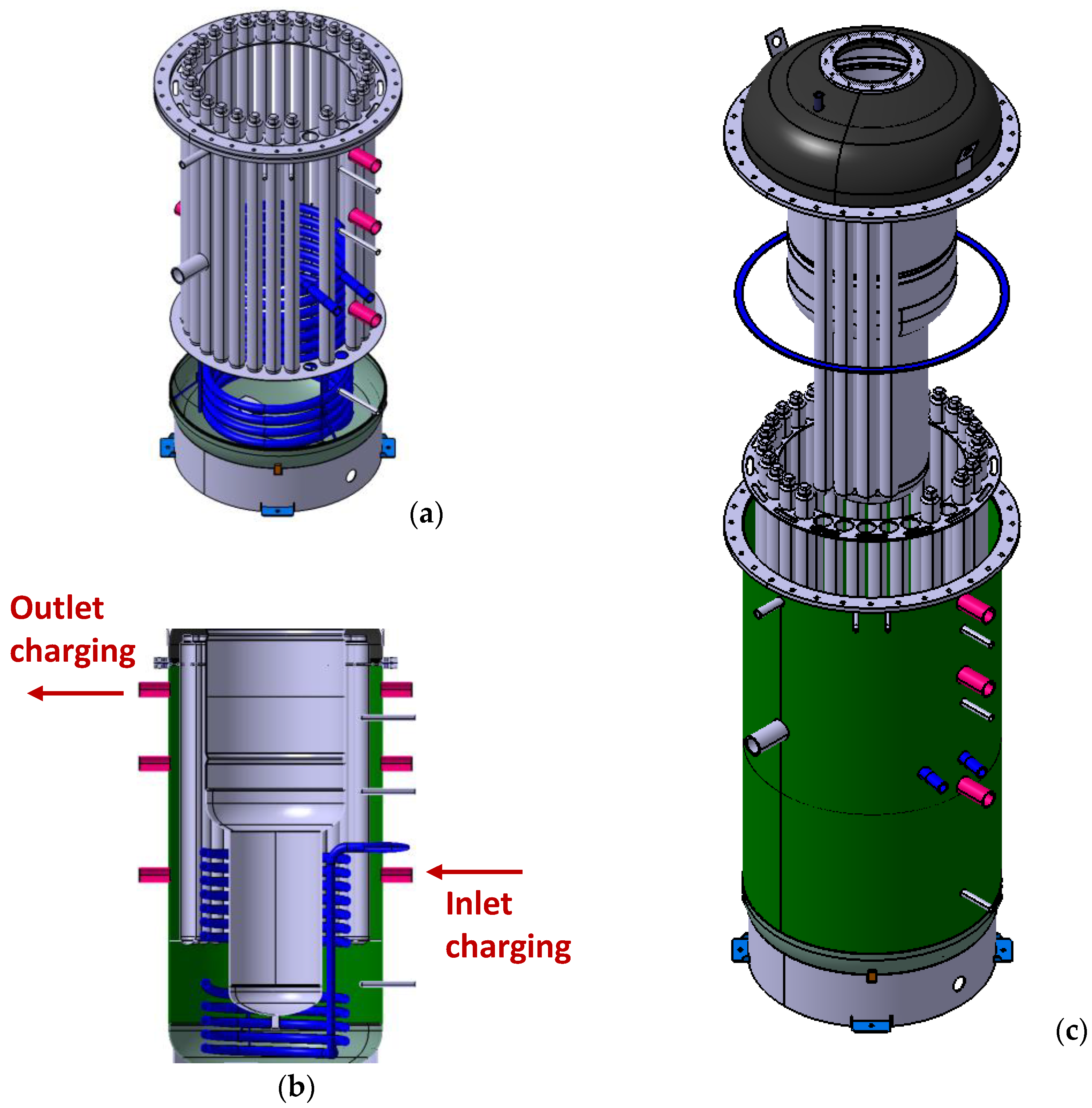
2.1. Hybrid Tank-in-Tank Storage Configuration

As previously introduced, the design phase of the hybrid sensible–latent TES started with some key objectives:
  • To employ a robust TES design, which was already commercially available, to minimize the cost and make the TES system suitable for integration in standard heating systems;
  • To investigate the possibility of physically separating technical water (used as heat transfer fluid) and DHW in order to avoid pollution of the DHW by PCM;
  • To integrate macro-encapsulated PCM with an optimized shape to maximize the amount of PCM inside the TES system.
In accordance with these selection criteria, the designed TES system was based on the well-known tank-in-tank architecture. This choice allowed this study’s authors to overcome possible safety restrictions related to the employment of PCM for DHW applications. Indeed, placing PCM macro-capsules within the external tank avoids any possible contamination of DHW, which is stored inside the internal tank. Regarding the selection of the most suitable commercial PCM, the authors referred to previous investigation performed on a small-scale, hybrid sensible–latent TES system, where different PCMs were tested [29]. According to the experimental outcomes, a commercial inorganic PCM, consisting of a mixture of hydrated salts characterized by a nominal melting temperature of 58 °C, known as S58, was selected. It was commercially provided by the PCM Products company [30] and can be obtained pre-macro-encapsulated. In particular, according to the tank-in-tank configuration under development, the tube shape was selected as macro-capsule, and these macro-capsules are made of high-density polyethylene (HDPE). Such capsules are 1 m in length with a diameter of 5 cm. The nominal features of the PCM and the employed macro-encapsules are summarized in Table 1.
The selected tank-in-tank architecture was chosen from a commercial provider, namely, Riello 7200 Kombi Plus [31]. Starting from the existing configuration, a re-design phase was carried out in order to adapt the external tank to allocate the PCM macro-capsules.
As represented in Figure 1, two circumferential, drilled plates were manufactured and welded in the external tank of the TES system. Particularly, as can be seen in Figure 1a, the holes on the bottom plate were drilled in order to hold the PCM tubes in specific positions while the holes on the top plate were realized with a diameter slightly larger than that of the tubes. Thus, the proper position of the macro-capsules inside the TES system was guaranteed while also allowing for the proper degree of freedom for the capsules’ expansion (both longitudinally and transversally) due to thermal expansion during the heating phase.
The maximum number of PCM macro-capsules that can be loaded inside the tank is 27. According to their nominal features reported in Table 1, this means that about 67 kg of PCM S58, displacing around 53 dm3 of water, can be loaded inside the hybrid sensible–latent TES system.
As shown in the TES section in Figure 1b, the employed combi-tank allows for the integration of more than one heating source. Indeed, the integration of an immersed copper coil can be commonly employed to charge the TES through an onsite renewable source such as a solar thermal field. In contrast, a direct exchange of the technical water contained in the external tank can be used when either a boiler or a heat pump is connected to the TES system. Furthermore, the water in the external tank can be used to provide spatial heating to the user, while the internal tank, which is kept separately from the technical water, guarantees the proper quality for DHW provision. Figure 1c reports the exploded configuration of the hybrid sensible–latent TES system, also showing the procedure used to install the PCM capsules.
Table 2 summarizes the main features of the designed and manufactured TES system.

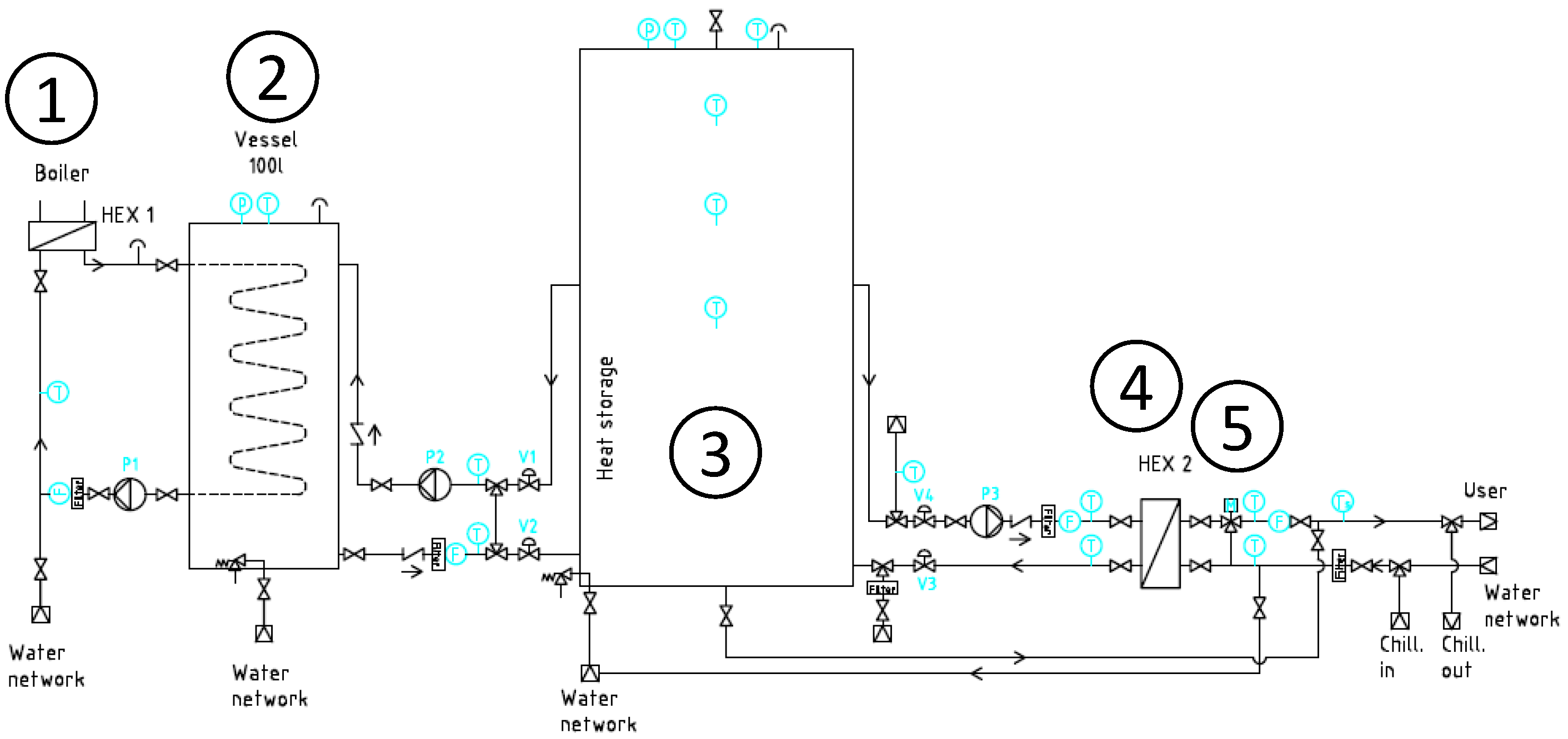
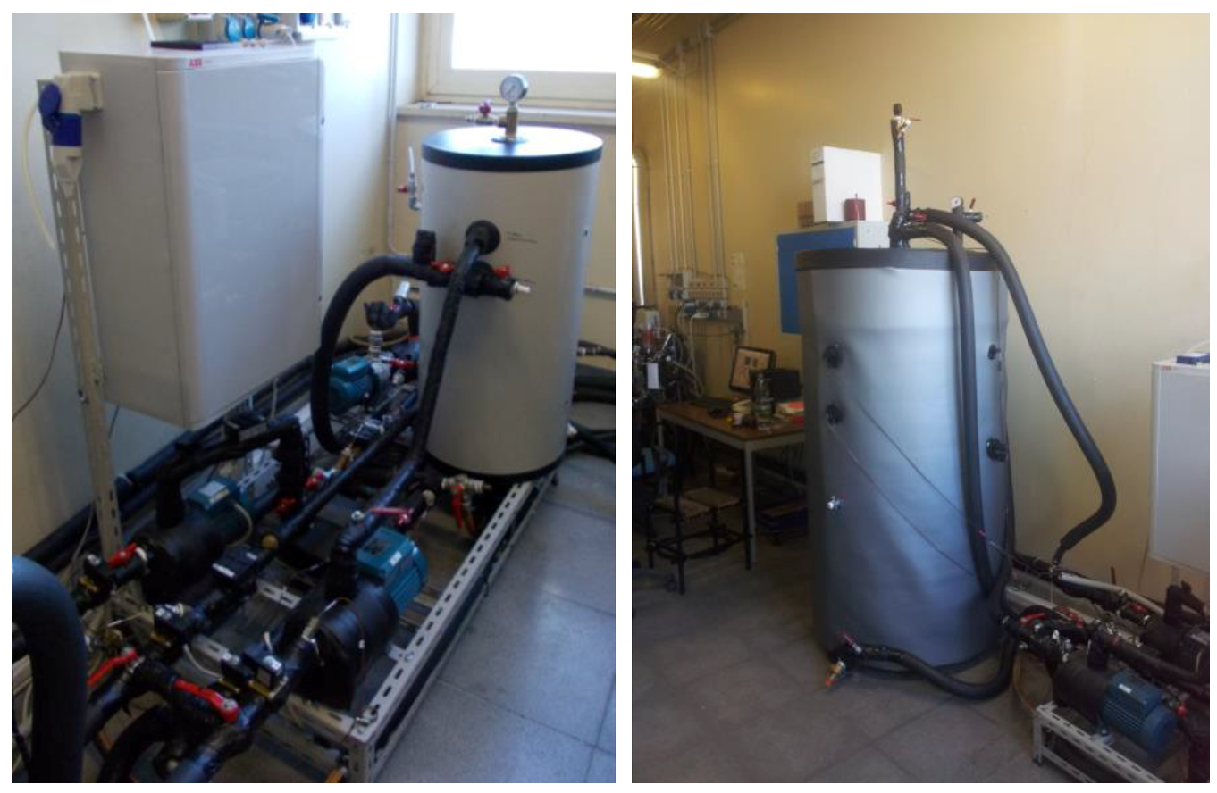
2.2. Testing Rig and Uncertainty Analysis

A dedicated testing rig already existing at CNR ITAE lab, which has already been described elsewhere [22,29], was upgraded to test the developed hybrid sensible–latent TES system. The test rig was designed to be able to mimic the operating conditions reported by the standard EN 12977-3 [32]. Accordingly, it allows for the performance of all the specified tests for the full characterization of DHW storage. Moreover, it can be employed for the simulation of different draw-off profiles, which are typical of domestic applications.
Figure 2 shows the hydraulic schematic of the testing rig. It can be considered to be composed of two separated sections: one operating at high temperature to simulate the charging phase, and one operating at low temperature for the discharging phase. The high-temperature heat source is a 24 kW electric boiler, employing a diathermic oil as heat transfer fluid carrier. A plate heat exchanger (HEX 1 in Figure 2) is employed to transfer heat from the oil loop to the water loop of the testing rig. A buffer vessel with a 100 dm3 volume (reported as 2 in Figure 2) is installed to smooth the fluctuation of the charging temperature to be provided to the heat storage under examination, which is labeled as 3 in Figure 2. The TES system under examination is also connected to the discharging side by an intermediate plate heat exchanger, HEX 2 in Figure 2, which avoids possible water contamination in the event of leakages from PCM capsules. Moreover, an automatic mixing valve, labeled as 5 in Figure 2, enables the setting of the water temperature to be delivered to the user during the discharging phase. Low temperature source can be simulated either directly by employing tap water or by a 12 kW electrical chiller, which allows for the setting of a quasi-constant temperature.
The realized testing rig was fully automatized by means of a control and monitoring software, implemented in LabView, which is able to control all the electric valves and pumps and also to acquire all the necessary data for the evaluation of the TES system’s performance, which mostly concern temperature and heat transfer fluid flows. Figure 3 depicts the installed testing rig at CNR ITAE lab as well as the hybrid sensible–latent TES system connected for the testing procedures.
Particular attention was paid to the selection of the proper sensors. The temperature is measured by means of thermocouples “type T” (characterized by an accuracy of ±0.5 °C), while the flow rate is measured by means of an ultrasonic sensor, which is able to work with different kind of fluids, and has a measuring range between Qmin = 0.016 dm3/s and Qmax = 1.66 dm3/s. The measuring error curve of the flow sensor shows an error in the measuring range of about 1% of the measured value. Accounting for the metrological characteristics of the employed sensors, an analysis of the experimental error was performed according to the international standards. Considering an accuracy of 0.5 °C for thermocouples, and 1% of the measured value for flow rate sensor, the error on the power measurement can be computed by the following expression:
u P = C P × Δ T × 0.01 × m ˙ 6 2 + m ˙ × C P × 0.5 3 2
where u(P) (kW) represents the error of the measured thermal power, CP (kJ/(kg K)) is the fluid specific heat, ΔT (K) is the measured temperature difference across each component, and (kg/s) is the mass flow rate. Of course, this value changes sensibly with the testing conditions. In general, especially during the discharging phases, due to the high employed flow rate and quite large temperature difference measured, a very low experimental error, about 2% of the overall discharged energy, was calculated.
As already mentioned, the performed TES characterization was based on the measurement of temperature difference and heat transfer fluid flow during charging and discharging phases, thus obtaining the complete energy balance during the operation. This allows for the evaluation of the most relevant parameters, such as energy storage capacity and average charging/discharging power. Nevertheless, in order to also monitor how the TES system behaves during the different phases, a set of temperature sensors was installed inside the tank. Specifically, Figure 4 represents the internal temperature sensors used to monitor the hybrid TES system. Three thermocouples, T1, T2 and T3, were used to monitor the evolution inside the external tank at different heights, while the T tank thermocouple was inserted inside the internal tank to monitor the DHW temperature.

2.3. Testing Conditions and Data Analysis

In order to experimentally characterize TES performance, three different testing conditions were considered, as already proposed in the literature [29]. These conditions were first applied to the tank-in-tank configuration operated as a sensible TES system (i.e., using water only) and then to the hybrid sensible–latent configuration, thus comparatively evaluating the achievable performance. The experimental conditions were as follows:
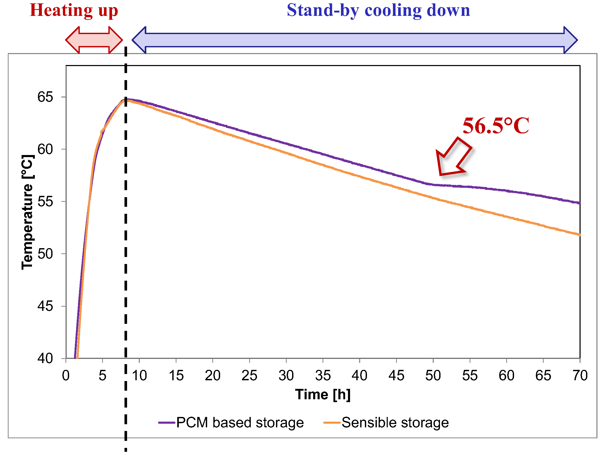
  • Stand-by cooldown. This test was mainly employed to evaluate the rate of heat dissipation to the surrounding environment (heat loss coefficient). The TES system is heated to a temperature above PCM’s melting point. Then, the heating is stopped, and the system is allowed to cool down for 60 h solely through heat loss, with the surrounding ambient temperature maintained at about 20 °C.
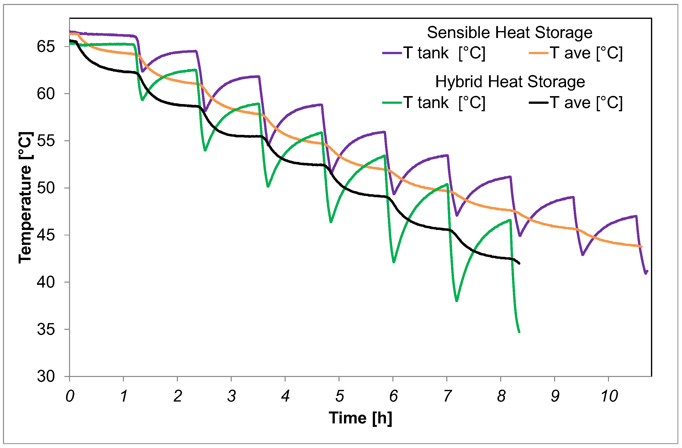
  • Test A. This test simulates the periodic DHW demand by the user. It consists of multiple 5 min discharges followed by a stand-by period. The TES system under examination is heated; afterwards, the DHW is withdrawn for 5 min with a subsequent stand-by period of 60 min. This procedure is repeated until the storage system is able to deliver DHW at a temperature of at least 45 °C.
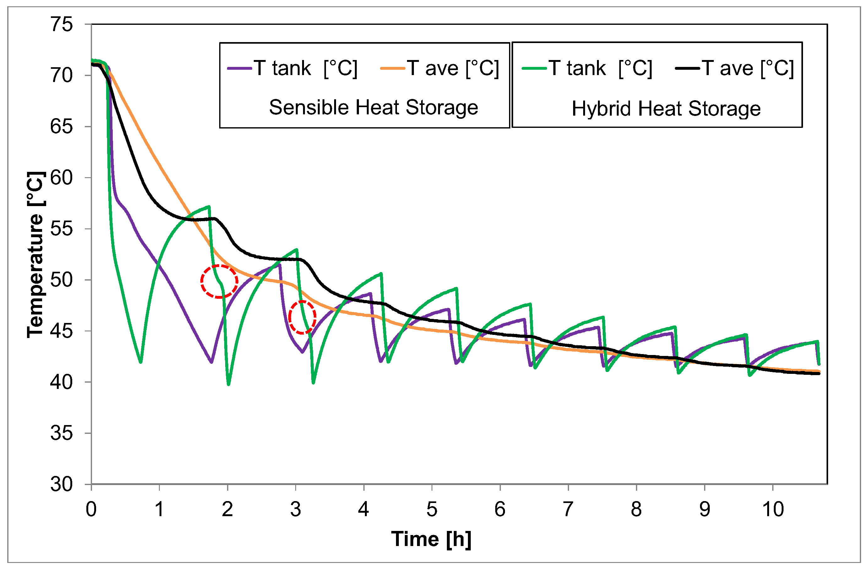
  • Test B. This test simulates a continuous DHW demand by the user. The TES system under examination is heated; afterwards, the DHW is continuously withdrawn as long as the DHW temperature is higher than 45 °C. Subsequently, the storage system is put on standby for 60 min, and then the procedure is repeated.
The different testing procedures were monitored by following the temperature evolution inside the TES system as well as in the external circuits.
All the tests were then evaluated by means of two Key Performance Indicators (KPIs): the energy stored to provide DHW, EDHW, and the equivalent amount of DHW produced, VDHW. These two KPIs were defined as:
E D H W = i = 1 n 0 t d i s c h m ˙   C p w   T o u t T i n   d t
where EDHW (MJ) represents the energy delivered by the TES system for DHW provision; Cpw (kJ/(kg K)) is the heat transfer fluid’s specific heat, in this case, water; Tout (°C) is the outlet temperature from the HEX 2 while Tin (°C) is the tap water inlet temperature; ṁ (kg/s) is the tap water mass flow rate; and tdisch (s) is the duration of each discharging phase.
V D H W = E D H W ρ w   C p w   T D H W T n e t
where TDHW (°C) is the DHW temperature to be delivered to the user, which, in this case, was fixed at 40 °C, and Tnet (°C) is the average seasonal tap water temperature, fixed at 15 °C. This evaluation is necessary in order to avoid the influence related to the fluctuation of inlet tap water temperature registered during experimental testing.

3. Results

3.1. Experimental Results

3.1.1. Stand-by Tests

The first-performed test was the stand-by cooling down test. It was repeated different times while changing the initial heating temperature and by comparing the effect of the charged PCM on the purely sensible tank.
Figure 5 compares two analogous stand-by tests, starting from 65 °C, and monitoring the temperature inside the DHW tank (T tank in Figure 4). As expected, in the first stage, there is a quasi-linear temperature decrease, which is mostly related to the sensible cooldown of the TES system due to heat loss. At the temperature of around 56.5 °C, the PCM starts solidifying, thus causing a plateau in the temperature measured inside the tank. This is proven by the slow phase change process which releases heat into the surrounding water, thus keeping it at an almost constant temperature. Since no heat withdrawal occurred in this test, the phase transition lasted almost 14 h. After the process was completed, the PCM was completely solidified, and the temperature started decreasing once again. In contrast, the sensible TES system faces a continuous temperature decrease throughout the test due to the heat loss to the environment. The rate of temperature decrease slows down as long as the tank temperature approaches the surrounding environmental temperature. As can be easily noticed, after around 60 h of standby, the hybrid TES system configuration maintains a temperature of almost 5 °C above the sensible one. This represents another beneficial effect of the PCM’s inclusion inside the tank.
As already presented in a previous scientific publication [29], the stand-by evolution temperature for the sensible TES configuration was employed to evaluate the heat loss coefficient. The temperature decay was simulated by means of a TRNSYS model of a “fully mixed” tank by varying the heat loss coefficient until the best fitting of the experimental data was achieved. The analysis revealed a heat loss coefficient of U = 3.5 W/K, which is in line with the standard heat loss coefficients of commercial tanks.

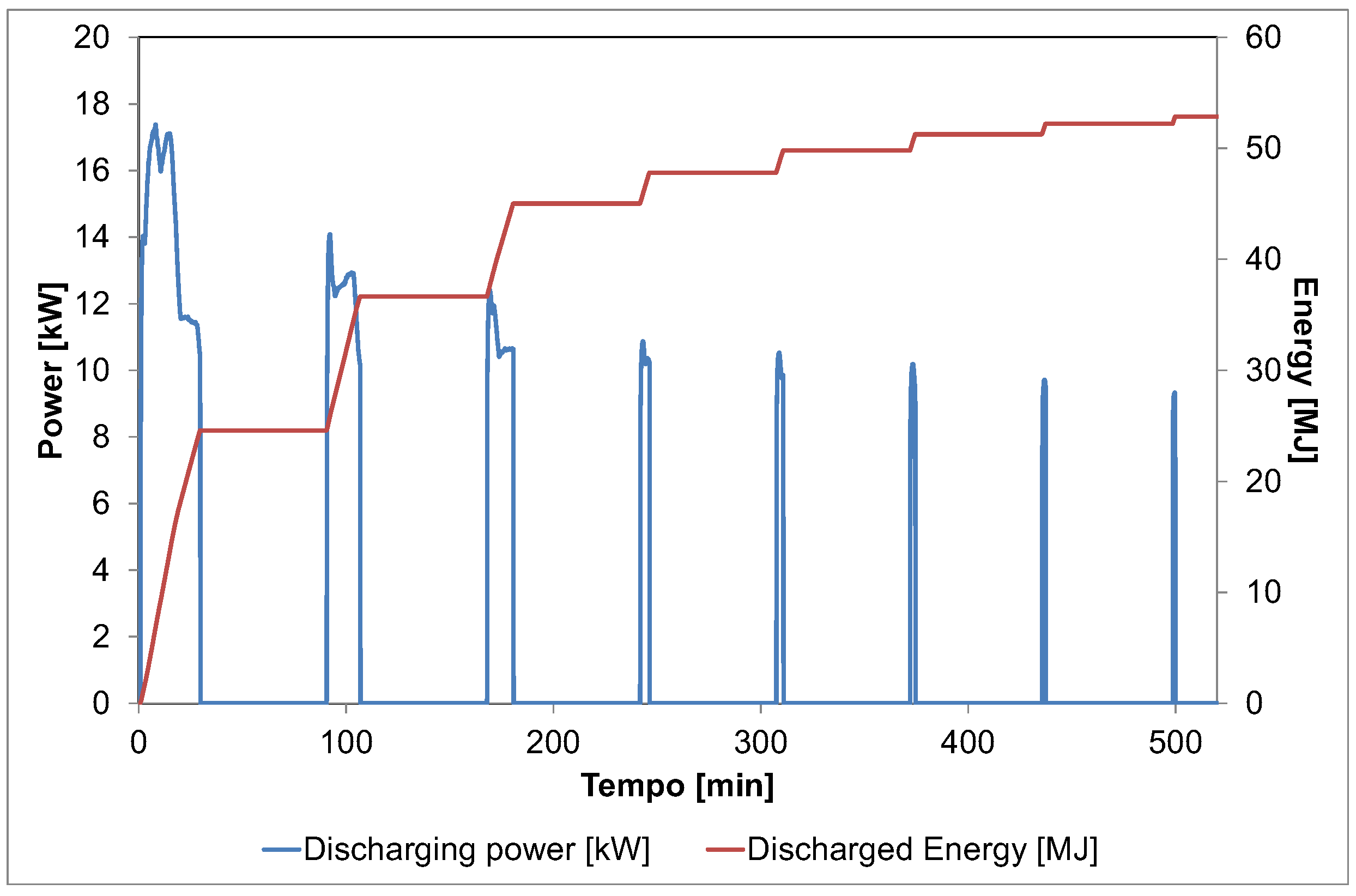
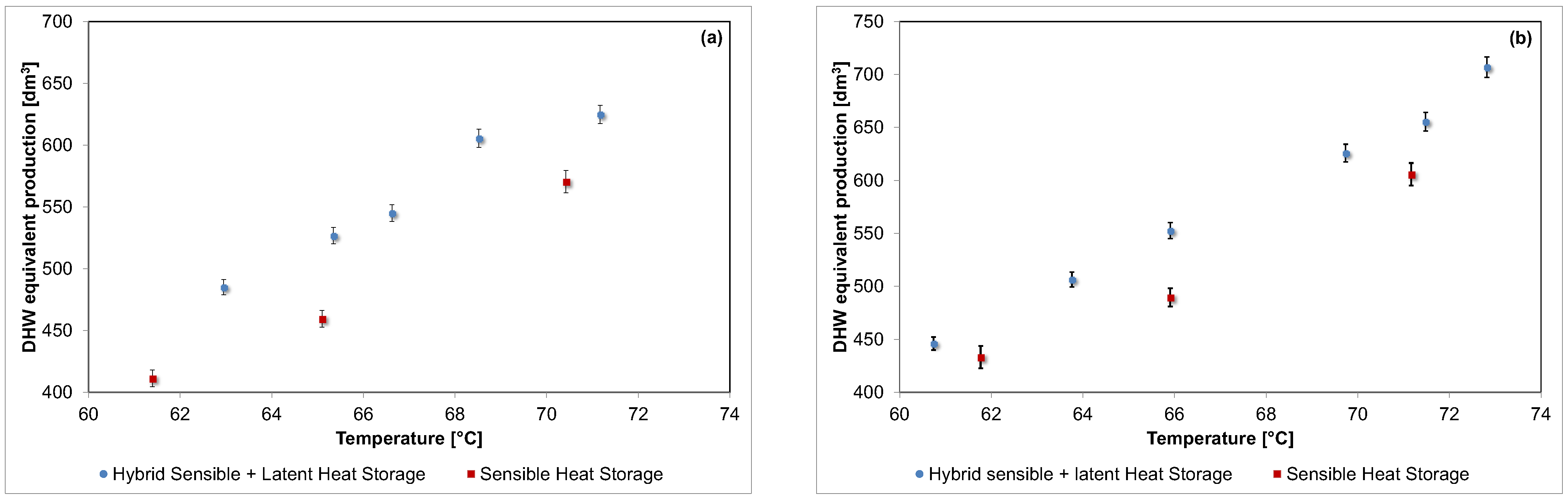
3.1.2. Dynamic Tests

The discharge tests were carried out by withdrawing DHW from the top of the internal tank and simulating the provision of hot water by exchanging heat through the intermediate HEX 2, as represented in Figure 2. All the performed tests used tap water on the secondary side of the HEX 2, with an average flow rate of 8 dm3/min. The automatic mixing valve installed after the HEX enabled the setting of a temperature to be delivered to the user of about 40 °C.
Test A
The first dynamic test performed was Test A, which mimicked the periodic withdrawal of DHW from the internal tank, followed by a stand-by period. Specifically, each withdrawal phase lasted 5 min and was followed by 30 min of standby. The test was repeated as long as the TES system was capable of producing 45 °C. Figure 6 compares the typical evolution of the discharging phase obtained in Test A for the sensible and hybrid TES configurations. The reported temperatures refer to the DHW tank (T tank) and to the temperature in the external tank obtained by averaging the values of the three thermocouples installed, as represented in Figure 4. The obtained temperature evolutions are peculiar for the tank-in-tank architecture. Indeed, during the short DHW discharge, there is a clearly identifiable temperature decrease, followed by a re-heating phase during the stand-by period, which was verified by the heat transfer from the external tank to the internal tank. Thus, the overall amount of DHW discharged is higher than the volume of the internal tank itself. This was verified by the potential to also exploit part of the thermal energy stored in the external tank. Since the PCM macro-capsules are also installed in the external tank, the energy transferred from the external to the internal tank during the stand-by periods is higher in the hybrid TES configuration.
Interestingly, when examining the evolution reported in Figure 6, the sensible TES system was able to perform more discharging runs than the hybrid TES system. This discrepancy is due to the different flow rates measured on the tap water loop in the different tests. Particularly, the tap water flow rates during the hybrid TES system’s discharge were around 20% higher than those in the tests performed with the sensible TES configuration. This is also confirmed by the higher temperature decrease measured for each discharging phase of the hybrid TES system compared to those of the sensible TES system. Nevertheless, the overall energy discharged from the DHW tank is higher for the hybrid TES system, as will be discussed in the following section.
Test B
The other set of dynamic testing conditions is represented by Test B, in which a continuous DHW withdrawal was simulated. The test was extended until the delivered temperature was above 45 °C. Afterwards, during the stand-by period, a re-heating phase occurred. As already reported for Test A, Figure 7 compares the sensible and hybrid TES systems’ evolutions under the same operating conditions. Due to the mismatch between the power extracted from the internal tank and the heat transfer capacity between the external and internal tanks, the temperature difference existing between the external and internal tanks at the end of each withdrawal phase is significant, e.g., 10 K after the first discharge, thus guaranteeing a high number of discharging phases for this testing condition as well.
The presence of PCM is more evident under Test B’s operating conditions. Indeed, as highlighted by the red circles in Figure 7, for the first two withdrawal phases, an inflection of the temperature decay measured inside the DHW tank is noticed whenever the temperature falls below that required for the solidification of the S58 PCM. At the same time, the average temperature in the external tank reaches a plateau. This means that the PCM macro-capsules increase the overall thermal inertia of the tank, thereby stabilizing the water temperature for a longer period in and around the DHW tank. This is also confirmed by the larger re-heating effect that occurred during the stand-by period of the hybrid TES system compared to the sensible one. In addition, in this case, as already highlighted for Test A, the discharging phases were shorter for the hybrid TES system due to a higher tap water flow rate available during its testing.
Figure 8 depicts the power evolution during the discharge of the hybrid TES system and the cumulative energy delivered in Test B. As expected, the discharging phase’s duration decreases continuously, and the DHW power is also reduced. This is caused by the lower temperature inside the DHW tank after each discharge, which limits the energy delivered as well as the power due to the lower temperature difference between the water in the tank and the tap water. Overall, the maximum discharge power is around 17 kW, with an average value of about 14 kW. The corresponding DHW energy discharged amounts to 52 MJ, which is in line with the theoretical value reported in Table 2.

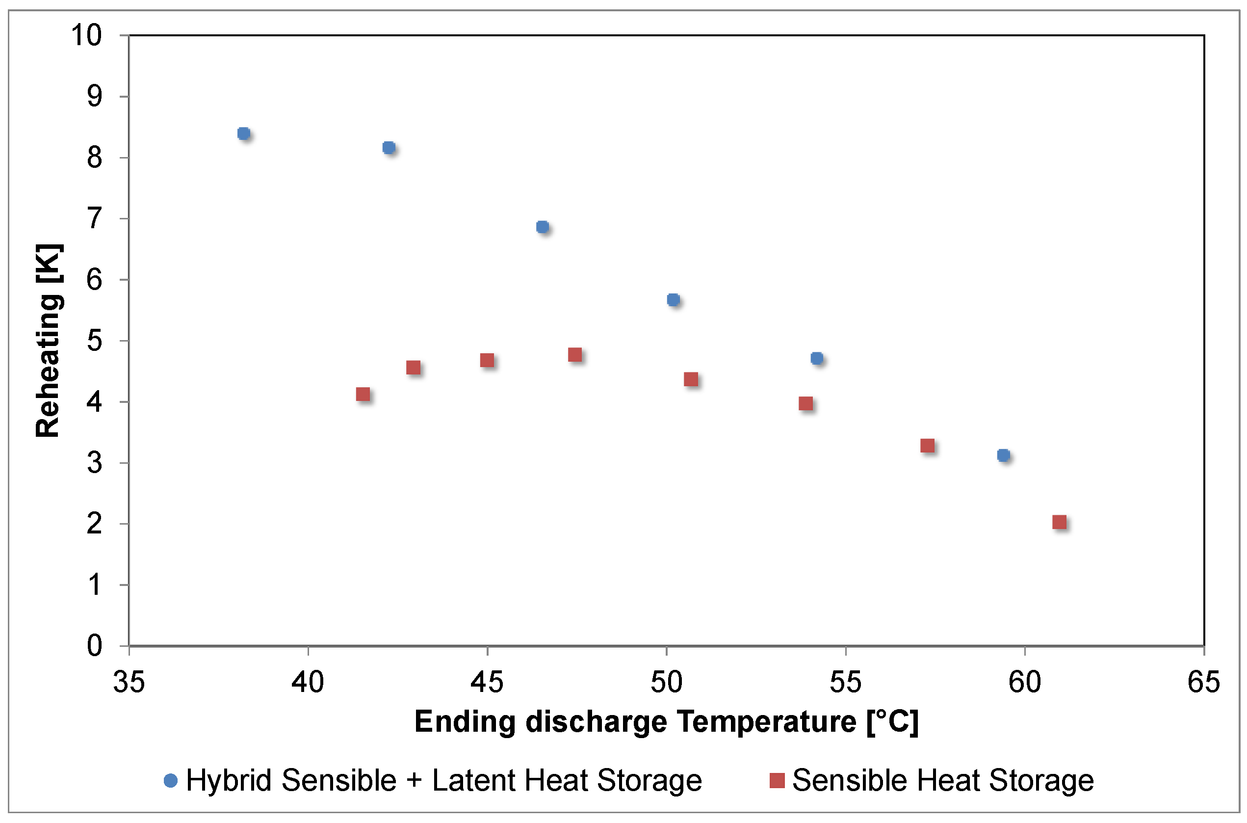
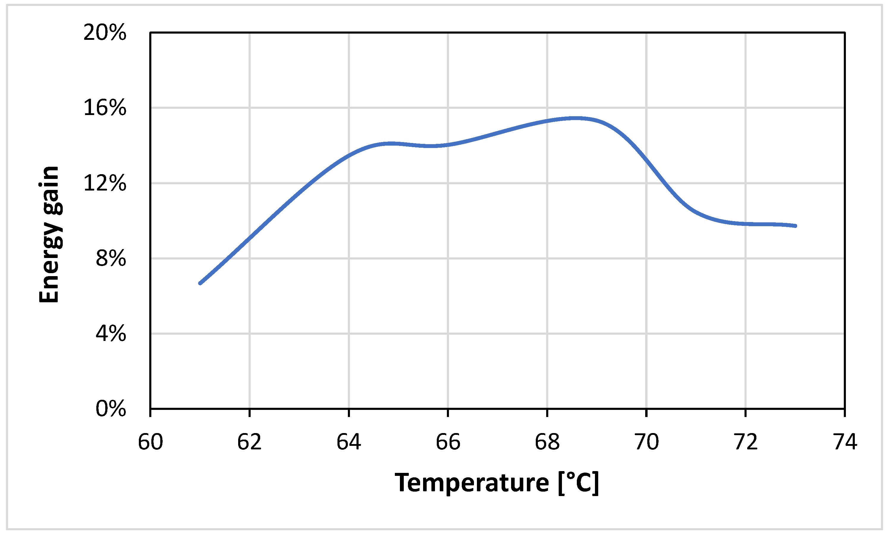
3.2. Performance Evaluation

Several different testing conditions were applied to the developed TES configurations in order to comparatively evaluate the benefits arising from the PCM’s integration in the hybrid TES system.
In order to evaluate how the PCM affects the operation of the TES system, the re-heating effects obtained for each stand-by phase under comparable Test A conditions are summarized in Figure 9. The degree of re-heating is evaluated in terms of the temperature increase that resulted after each discharging phase as a function of the temperature at which each phase ended. As can be surmised from Figure 9, no appreciable deviation was obtained down to 50 °C. Below this temperature range, while the sensible TES system almost stabilizes the re-heating effect to around 4 K, the hybrid TES system continues increasing the temperature difference, even reaching values above 8 K. This effect is related to the increased energy storage in the external tank provided by the PCM and by the fact that the energy is released efficiently only when the temperature difference between water and PCM is sufficiently high; thus, the energy release is somehow self-regulated. Overall, the re-heating effect is about 16% higher for the hybrid TES system than the sensible TES system. This is related to the energy storage increase, which will be discussed shortly.
The overall effect of the PCM’s inclusion was analyzed through an evaluation of the energy storage capacity and the equivalent DHW production, as defined earlier in Equations (2) and (3). Specifically, the equivalent DHW production obtained for the different tested conditions is represented in Figure 10. The estimated error, which was experimentally confirmed by three different runs for each operating condition, consistently turned out to be around 2%.
As expected, for both the sensible and latent TES systems, a higher level of water production (and thus discharged energy) is registered when the initial temperature is increased. In general, the hybrid TES system always presents higher levels of DHW production compared to the sensible TES system. As reported in Figure 10, the closer the starting temperature is to the phase transition, the higher the level of DHW production. This is because the effect of the melting enthalpy is emphasized when the system operates slightly above the melting temperature. Overall, the increase in DHW production (and discharged energy) ranges between 13% and 8% if compared to the sensible TES system, and it is not dependent on the operating conditions since the results obtained for Test A and Test B are quite comparable.

4. Discussion

The results obtained from the experimental tests were used for the further evaluation of the storage system with the aim of suggesting further enhancements of the system and providing useful design guidelines.

4.1. Comparison with Other Studies and Heat Transfer Considerations

As stated in the introduction, several studies are available in the literature regarding the development of PCM-based DHW tanks. However, for the sake of comparison, only recent works employing a similar design to the one investigated in this work were selected.
Pop et al., in [26], used a numerical model to investigate a storage tank employed for the provision of hot water to a swimming pool. This was a hybrid storage tank with sensible water and the inclusion of some PCM cylinders, as in the present case. Commercial PCMs with melting temperature of 55 °C and 46.85 °C were considered for the analysis. For a 1.5 m3 storage tank, around 0.4 m3 is occupied by the PCM cylinders, which is about double that of the packing factor of the system presented in herein. The results indicated that an around 25% volume reduction can be obtained for the storage system by using PCMs, so longs as the same equivalent volume of DHW produced is considered. However, the results also indicated that the thermal losses due to the heat exchange of the PCM with the surrounding water reduce the advantage of the application of the hybrid storage system over the sensible one only in terms of a longer storage time (i.e., more than half a day) unless proper insulation is used. For the present case, an around 13% volume reduction was measured, which is in line with the findings in the literature, since, in the work conducted by Pop et al., the amount of PCM was double that in the current design.
Carmona et al. [33] presented a numerical analysis of a hybrid system with a conceptual design similar to the present one, i.e., a storage tank wherein a portion of the water is replaced by cylinders filled with paraffinic PCM with a nominal melting temperature of 55 °C. Out of the overall 65 dm3 of the tank, 25 dm3 is occupied by the PCM cylinders, which is about three times higher than the current design. The PCM cylinders are arranged in an almost identical layout as that of the current design, i.e., inserted into a custom-made metal sheet along the storage circumference. The tests carried out were similar to the ones presented in the previous section, with the remarkable difference that, instead of the approach denoted as Test A presented in this paper, a test with three discharges over 24 h was considered in the model. The results are presented in terms of energy and exergy analysis and the same trend was observed: when 40% PCM is used, the efficiency increases by around 16% relative to the case without PCM, with the actual value depending on the type of operating cycle. The value is lower than the one obtained in the present study, with an around 13% energy increase measured with a lower amount of PCM. This may be due to the fact that by increasing the amount of PCM, the quantity of water between the cylinders reduces; therefore, the convection effect between the capsules and the water inside the tank is also lower. At the same time, the ∆T between the PCM and the sensible medium reduces, thus further preventing heat exchange.
Fadl et al. in [34] and in [35] presented an experimental investigation of a PCM-based storage unit for DHW provision. Compared to the present case, these authors’ selected PCM’s melting point was lower, i.e., 44 °C. The tank was a cuboid filled with the PCM and including a copper coil. The analysis focused mainly on the design and the orientation of the heat exchanger. The main interesting results were related to the effect of the operating parameters; the parameter that yielded the highest influence on the energy recovered was the temperature gradient between the PCM and the HTF. As shown in the previous section, this is also the case for the current design, which is due to the fact that the heat conduction in the PCM is the main limiting factor for heat transfer. This further stresses the advantage of a hybrid sensible–latent TES system over a latent one, especially with respect to discontinuous discharging, since there is a temperature gradient between water and PCM that guarantees better exploitation of the energy stored in the PCM and a faster response time. Indeed, in the papers by Fadl et al., a discharging time of up to 350 min for an 82 dm3 system was measured, while for the present case, 500 min of discharging time was measured for a TES system that is four times larger.
All the designs presented so far, and in the literature in general, do not consider one of the main issues that inspired the design of the TES system discussed herein, i.e., the need to separate the DHW from the water that is in contact with the PCM to avoid contamination in the case of PCM leakage. This aspect is considered for the TES system presented by Deng et al. [36], which consists of DHW with PCM in the mantle, in which charge and discharge is realized through copper spiral heat exchangers. A total of 35 kg of PCM is filled in the mantle, whereas the overall volume of the storage is 148 dm3. The amount of PCM is then about double that in the case investigated herein. The selected PCM was sodium acetate tri-hydrate with a melting temperature of 58 °C. The results indicated that, for the selected layout, the design of the heat exchangers for charging and discharging is critical since a mismatch in these parameters caused much lower performance than expected. Moreover, only around 70% of the PCM was estimated to be active in the process. Alternatively, in the current design, the theoretical and measured storage capacities agreed, indicating that the layout chosen guarantees that the PCM reacts fully.

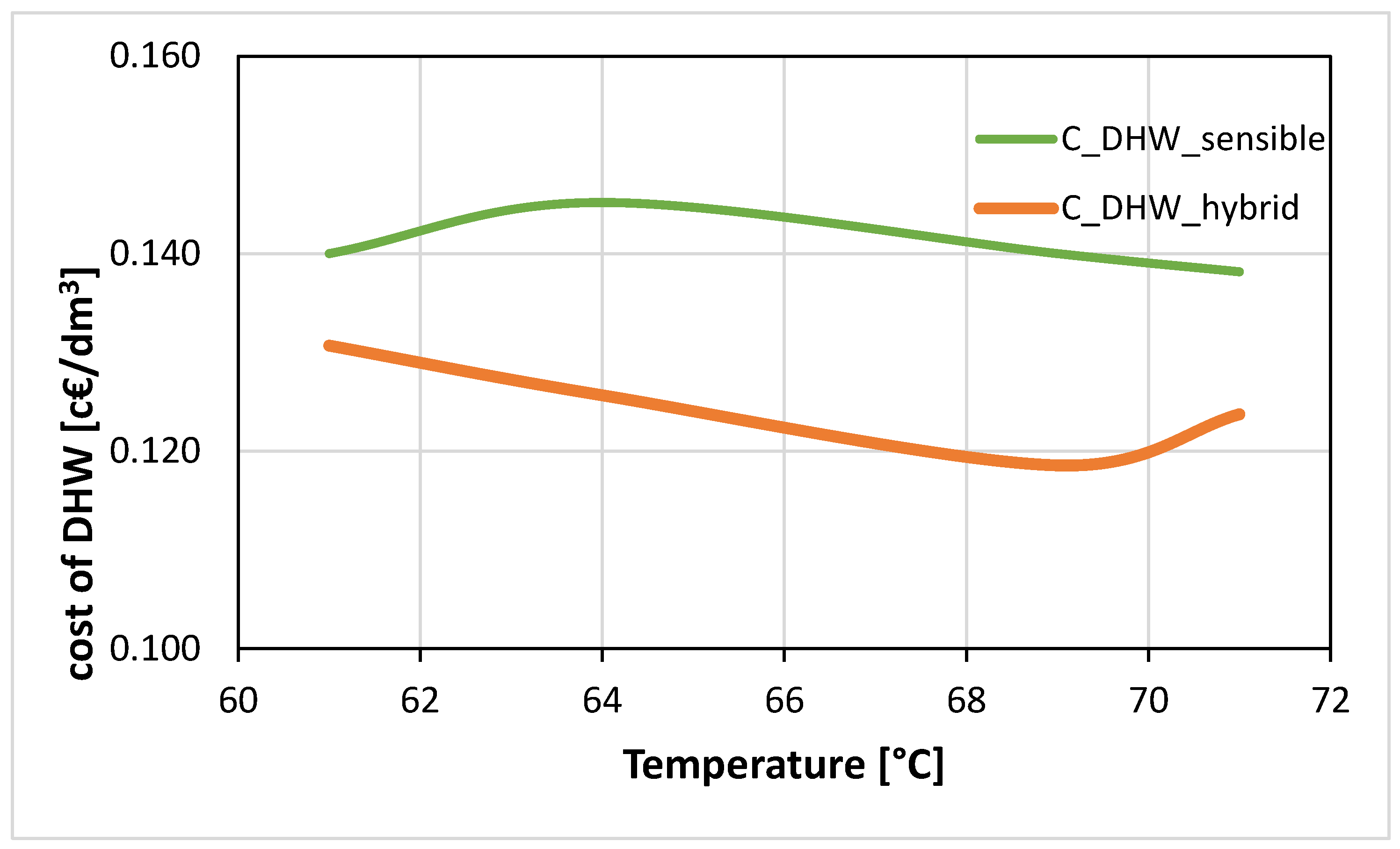
4.2. Energy and Economic Analysis

Since, as previously discussed, the operational cycle considered does not significantly affect the achieved results, the following analysis is based on the results from test B. Figure 11 shows the energy gain derived from the use of the hybrid tank instead of the sensible one as a function of tank temperature. It is possible to notice that the maximum energy gain is achieved in the range of 64–70 °C, which is a charging temperature that can be easily reached even with flat plate solar collectors or the current commercial district-heating networks.
The economic benefits arising from the use of the TES system are quantified on the basis of the energy gain in accordance with the Italian national unit price for energy (PUN) [37], which is the reference value for the Italian energy market. This does not consider specific discounts or rates from the various utilities and operators, but it was considered the fairest means of comparison. For December 2022, the cost of energy was 0.294 EUR/kWh. The economic benefit was calculated as the average price needed to obtain 1 L of DHW:
C D H W = E c h a r g e d * P U N V D H W
where Echarged is the energy charged inside the storage system (kWh) for each case and VDHW is the equivalent volume presented before. The results are shown in Figure 12 it is possible to notice the investigated hybrid TES system can provide financial benefits, which can be maximized when a higher charging temperature is considered (until reaching 70 °C). Instead, below 62 °C and above 70 °C of the initial tank temperature, the economic benefit is lower. This indicates that the operating temperature is another key parameter in the selection of the operation scheme of the storage cases. Considering what was discussed in the previous section regarding the results of other studies’ designs as well as the results of these analyses, it is possible to state that it could be more beneficial to increase the amount of PCM in the storage system, but a detailed numerical analysis is needed to identify the optimal PCM amount, alongside a consideration of the adaptation of the tank-in-tank TES design.

5. Conclusions

This paper investigated the ability of an innovative hybrid sensible–latent TES system based on a commercially available tank-in-tank TES system and macro-encapsulated PCM to increase the overall energy storage density of TES systems while guaranteeing a reasonable cost. The developed configuration used a salt hydrate with a melting temperature of 58 °C, suitable for DHW and space-heating applications, which had already been successfully employed in previous investigations in the literature.
Different experimental characterizations were performed in the lab with the aim of validating the heat losses to the surrounding environment during stand-by periods as well as mimicking the variable discharging operating conditions defined by the European standards for the testing of solar-combi storage. The obtained results highlighted the main feature of the operation of the tank-in-tank configuration, namely, the re-heating effect of the internal tank (i.e., the DHW one) due to the heat exchange with the external tank during stand-by periods. This also allows for the exploitation of a share of the energy stored in the external tank to provide DHW to the user.
A comparative analysis was carried out by testing both the sensible and hybrid configurations under the same conditions. The experimental results showed the ability of the PCM to keep the external tank warm for longer periods, especially during the deep discharging phases and the stand-by periods, thus transferring a larger amount of thermal energy to the internal DHW tank. The achievable discharging power reached peaks of 17 kW with an average power of about 14 kW, which overcomes limitations often encountered for latent TES systems. Overall, an increase in the energy storage capacity and corresponding DHW provision of up to 16% can be guaranteed by the developed configuration, especially when the charging temperature is maintained slightly above the melting temperature of the PCM, in order to maximally exploit the effect of the melting enthalpy.
The results obtained were also compared to other designs and recent works presented in the literature, highlighting the benefits of the selected layouts and, at the same time, indicating that a higher benefit could be achieved if the PCM amount is increased inside the tank. Economic and energy benefits were also calculated and were maximal when considering an operating range of the tank for charging of 62–68 °C.
This paper demonstrated, for the first time, the possibility of efficiently employing a tank-in-tank configuration to realize a hybrid sensible–latent TES system, thus making it suitable for quick commercialization.

Author Contributions

Conceptualization, A.F. (Andrea Frazzica) and A.F. (Angelo Freni); methodology, A.F. (Andrea Frazzica) and V.P.; formal analysis, A.F. (Andrea Frazzica); investigation, A.F. (Andrea Frazzica) and V.P.; writing—original draft preparation, A.F. (Andrea Frazzica); writing—review and editing, A.F. (Angelo Freni) and V.P.; visualization, A.F. (Andrea Frazzica); supervision, A.F. (Angelo Freni); project administration, A.F. (Andrea Frazzica); All authors have read and agreed to the published version of the manuscript.

Funding

This work was partially supported by Italian Ministry for the Economic Development: ‘‘Progetto PIACE, Piattaforma intelligente, Integrata e Adattativa di micro Cogenerazione ad elevata Efficienza per usi residenziali—Industria 2015” (Grant No. 00024EE01).

Data Availability Statement

The data presented in this study are available on request from the corresponding author.

Conflicts of Interest

The authors declare no conflict of interest.

References

  1. Maturo, A.; Buonomano, A.; Athienitis, A. Design for energy flexibility in smart buildings through solar based and thermal storage systems: Modelling, simulation and control for the system optimization. Energy 2022, 260, 125024. [Google Scholar] [CrossRef]
  2. Rehman, O.A.; Palomba, V.; Frazzica, A.; Cabeza, L.F. Enabling Technologies for Sector Coupling: A Review on the Role of Heat Pumps and Thermal Energy Storage. Energies 2021, 14, 8195. [Google Scholar] [CrossRef]
  3. Kauko, H.; Sevault, A.; Vasta, S.; Zondag, H.A.; Beck, A.; Drexler-Schmid, G.; Garcia Polanco, N.R.; Ma, Z.; Roskilly, A.P. Industrial Thermal Energy Storage Supporting the Transition to Decarbonise Industry; SINTEF: Trondheim, Norway, 2022. [Google Scholar]
  4. Hansen, A.R.; Leiria, D.; Johra, H.; Marszal-Pomianowska, A. Who Produces the Peaks? Household Variation in Peak Energy Demand for Space Heating and Domestic Hot Water. Energies 2022, 15, 9505. [Google Scholar] [CrossRef]
  5. Faraj, K.; Khaled, M.; Faraj, J.; Hachem, F.; Castelain, C. A review on phase change materials for thermal energy storage in buildings: Heating and hybrid applications. J. Energy Storage 2021, 33, 101913. [Google Scholar] [CrossRef]
  6. Koçak, B.; Fernandez, A.I.; Paksoy, H. Review on sensible thermal energy storage for industrial solar applications and sustainability aspects. Sol. Energy 2020, 209, 135–169. [Google Scholar] [CrossRef]
  7. Gao, Y.; He, F.; Xu, T.; Meng, X.; Zhang, M.; Yan, L.; Gao, W. Thermal performance analysis of sensible and latent heat thermal energy storage tanks: A contrastive experiment. J. Build. Eng. 2020, 32, 101713. [Google Scholar] [CrossRef]
  8. Mehling, H.; Brütting, M.; Haussmann, T. PCM products and their fields of application—An overview of the state in 2020/2021. J. Energy Storage 2022, 51, 104354. [Google Scholar] [CrossRef]
  9. Fumey, B.; Weber, R.; Baldini, L. Sorption based long-term thermal energy storage—Process classification and analysis of performance limitations: A review. Renew. Sustain. Energy Rev. 2019, 111, 57–74. [Google Scholar] [CrossRef]
  10. Palomba, V.; Frazzica, A. Recent advancements in sorption technology for solar thermal energy storage applications. Sol. Energy 2019, 192, 69–105. [Google Scholar] [CrossRef]
  11. Mazman, M.; Cabeza, L.F.; Mehling, H.; Nogues, M.; Evliya, H.; Paksoy, H.Ö. Utilization of phase change materials in solar domestic hot water systems. Renew. Energy 2009, 34, 1639–1643. [Google Scholar] [CrossRef]
  12. Aridi, R.; Yehya, A. Review on the sustainability of phase-change materials used in buildings. Energy Convers. Manag. X 2022, 15, 100237. [Google Scholar] [CrossRef]
  13. Kundu, R.; Kar, S.P.; Sarangi, R. Performance enhancement with inorganic phase change materials for the application of thermal energy storage: A critical review. Energy Storage 2022, 4, e320. [Google Scholar] [CrossRef]
  14. Sheikh, Y.; Fatih Orhan, M.; Kanoglu, M. Heat transfer enhancement of a bio-based PCM/metal foam composite heat sink. Therm. Sci. Eng. Prog. 2022, 36, 101536. [Google Scholar] [CrossRef]
  15. Liu, G.; Xiao, T.; Guo, J.; Wei, P.; Yang, X.; Hooman, K. Melting and solidification of phase change materials in metal foam filled thermal energy storage tank: Evaluation on gradient in pore structure. Appl. Therm. Eng. 2022, 212, 118564. [Google Scholar] [CrossRef]
  16. Yazici, M.Y.; Saglam, M.; Aydin, O.; Avci, M. Thermal energy storage performance of PCM/graphite matrix composite in a tube-in-shell geometry. Therm. Sci. Eng. Prog. 2021, 23, 100915. [Google Scholar] [CrossRef]
  17. Mselle, B.D.; Zsembinszki, G.; Borri, E.; Vérez, D.; Cabeza, L.F. Trends and future perspectives on the integration of phase change materials in heat exchangers. J. Energy Storage 2021, 38, 102544. [Google Scholar] [CrossRef]
  18. Sciacovelli, A.; Gagliardi, F.; Verda, V. Maximization of performance of a PCM latent heat storage system with innovative fins. Appl. Energy 2015, 137, 707–715. [Google Scholar] [CrossRef]
  19. Sun, X.; Mahdi, J.M.; Mohammed, H.I.; Majdi, H.S.; Zixiong, W.; Talebizadehsardari, P. Solidification Enhancement in a Triple-Tube Latent Heat Energy Storage System Using Twisted Fins. Energies 2021, 14, 7179. [Google Scholar] [CrossRef]
  20. He, F.; Yan, B.; Zou, J.; Hu, C.; Meng, X.; Gao, W. Experimental evaluation of the effect of perforated spiral fins on the thermal performance of latent heat storage units. J. Energy Storage 2023, 58, 106359. [Google Scholar] [CrossRef]
  21. Herbinger, F.; Groulx, D. Experimental comparative analysis of finned-tube PCM-heat exchangers’ performance. Appl. Therm. Eng. 2022, 211, 118532. [Google Scholar] [CrossRef]
  22. Frazzica, A.; Manzan, M.; Palomba, V.; Brancato, V.; Freni, A.; Pezzi, A.; Vaglieco, B.M. Experimental Validation and Numerical Simulation of a Hybrid Sensible-Latent Thermal Energy Storage for Hot Water Provision on Ships. Energies 2022, 15, 2596. [Google Scholar] [CrossRef]
  23. Suresh, C.; Saini, R.P. Experimental study on combined sensible-latent heat storage system for different volume fractions of PCM. Sol. Energy 2020, 212, 282–296. [Google Scholar] [CrossRef]
  24. Aziz, S.; Amin, N.A.M.; Abdul Majid, M.S.; Bruno, F.; Belusko, M. Effectiveness-NTU correlation for a TES tank comprising a PCM encapsulated in a sphere with heat transfer enhancement. Appl. Therm. Eng. 2018, 143, 1003–1010. [Google Scholar] [CrossRef]
  25. Grabo, M.; Acar, E.; Kenig, E.Y. Modeling and improvement of a packed bed latent heat storage filled with non-spherical encapsulated PCM-Elements. Renew. Energy 2021, 173, 1087–1097. [Google Scholar] [CrossRef]
  26. Pop, O.G.; Balan, M.C. A numerical analysis on the performance of DHW storage tanks with immersed PCM cylinders. Appl. Therm. Eng. 2021, 197, 117386. [Google Scholar] [CrossRef]
  27. Erdemir, D.; Ozbekler, A.; Altuntop, N. Experimental investigation on the effect of the ratio of tank volume to total capsulized paraffin volume on hot water output for a mantled hot water tank. Sol. Energy 2022, 239, 294–306. [Google Scholar] [CrossRef]
  28. Englmair, G.; Furbo, S.; Dannemand, M.; Fan, J. Experimental investigation of a tank-in-tank heat storage unit utilizing stable supercooling of sodium acetate trihydrate. Appl. Therm. Eng. 2020, 167, 114709. [Google Scholar] [CrossRef]
  29. Frazzica, A.; Manzan, M.; Sapienza, A.; Freni, A.; Toniato, G.; Restuccia, G. Experimental testing of a hybrid sensible-latent heat storage system for domestic hot water applications. Appl. Energy 2016, 183, 1157–1167. [Google Scholar] [CrossRef]
  30. PCM Products Catalogue. Available online: https://www.pcmproducts.net/files/PlusICERange2021-1.pdf (accessed on 2 January 2023).
  31. Riello combi Tanks. Available online: File:///C:/Users/Andrea/Downloads/Schedatecnicocommerciale-0.pdf (accessed on 2 January 2023).
  32. UNI EN 12977-3:2018; Impianti Solari Termici e loro Componenti. Impianti Assemblati su Specifica. Parte 3: Metodi di Prova Della Prestazione per Serbatoi di Stoccaggio Degli Scaldacqua Solari. UNI: Tokyo, Japan, 2009.
  33. Carmona, M.; Rincón, A.; Gulfo, L. Energy and exergy model with parametric study of a hot water storage tank with PCM for domestic applications and experimental validation for multiple operational scenarios. Energy Convers. Manag. 2020, 222, 113189. [Google Scholar] [CrossRef]
  34. Fadl, M.; Mahon, D.; Eames, P.C. Thermal performance analysis of compact thermal energy storage unit-An experimental study. Int. J. Heat Mass Transf. 2021, 173, 121262. [Google Scholar] [CrossRef]
  35. Fadl, M.; Eames, P.C. An experimental investigation of the heat transfer and energy storage characteristics of a compact latent heat thermal energy storage system for domestic hot water applications. Energy 2019, 188, 116083. [Google Scholar] [CrossRef]
  36. Deng, J.; Furbo, S.; Kong, W.; Fan, J. Thermal performance assessment and improvement of a solar domestic hot water tank with PCM in the mantle. Energy Build. 2018, 172, 10–21. [Google Scholar] [CrossRef]
  37. Mercato Elettrico Italiano. Available online: https://luce-gas.it/guida/mercato/andamento-prezzo/energia-elettrica (accessed on 2 January 2023).
Figure 1. Detailed representation of the designed hybrid TES system: (a) 3D view of the internal structure, highlighting the PCM macro-capsules along the diameter and the internal spiral HEX; (b) 2D section of the hybrid tank, with the different hydraulic connections and the internal tank inserted; (c) overall exploded 3D view with the different components highlighted.
Energies 16 01875 g001
Figure 2. Hydraulic schematic of the TES test rig at ITAE lab: ➀, electric boiler high-temperature heat source; ➁, intermediate buffer; ➂, TES system under examination; ➃, intermediate HEX on the energy withdrawal side; ➄, automatic mixing valve.
Energies 16 01875 g002
Figure 3. Picture of the testing rig installed at ITAE lab (left-hand side) and hybrid TES system connected under test conditions (right-hand side).
Energies 16 01875 g003
Figure 4. Schematic representation of the internal temperature sensors integrated in the hybrid TES system to monitor the process evolution.
Energies 16 01875 g004
Figure 5. Temperature evolution inside the internal tank of the hybrid TES system during the stand-by cooldown process. The reference thermocouple is the T tank, as represented in Figure 4.
Energies 16 01875 g005
Figure 6. Dynamic evolution of the temperatures inside the TES system in sensible and hybrid configurations obtained under Test A conditions.
Energies 16 01875 g006
Figure 7. Dynamic evolution of the temperatures inside the TES system in sensible and hybrid configurations under Test B conditions. Highlighted in red: the phase transition effect in the hybrid TES system.
Energies 16 01875 g007
Figure 8. Thermal power and energy discharged by the hybrid TES system during Test B.
Energies 16 01875 g008
Figure 9. Difference in reheating effect measured obtained for the sensible and hybrid TES configurations during analogous Test A.
Energies 16 01875 g009
Figure 10. Comparison of equivalent DHW production for sensible and hybrid TES configurations obtained under Test A (a) and Test B (b) operating conditions.
Energies 16 01875 g010
Figure 11. Energy gain derived from the use of the hybrid tank instead of the sensible one.
Energies 16 01875 g011
Figure 12. Results of the economic analysis.
Energies 16 01875 g012
Table 1. Main features of the commercial macro-encapsulated PCM [22].
PCM 58—Macro Encapsulation
Nominal melting temperature (°C)58
Density (kg/m3)1505
Nominal latent heat (kJ/kg)145
Specific heat capacity (solid) (kJ/kg K)2.55
Thermal conductivity (W/m K)0.69
Macro capsule (tube) length (m)1
Macro capsule (tube) diameter (m)0.05
Macro capsule (tube) weight (kg)2.65
Table 2. Main features of the designed hybrid TES system.
Hybrid Sensible–Latent TES system Features
External tank volume (dm3)380
Internal DHW tank volume (dm3)160
Tank external diameter (m)0.89
Tank height (m)1.74
PCM macro-capsules number27
Maximum nominal operating temperature (°C)80
Theoretical energy storage capacity (MJ)55
Theoretical energy storage density (MJ/m3)137.5
Insulating materialexpanded polyurethane
Thermal conductivity of insulation (W/(mK))0.03
Insulating material thickness (mm)90
Disclaimer/Publisher’s Note: The statements, opinions and data contained in all publications are solely those of the individual author(s) and contributor(s) and not of MDPI and/or the editor(s). MDPI and/or the editor(s) disclaim responsibility for any injury to people or property resulting from any ideas, methods, instructions or products referred to in the content.

