
Economic and Energetic Assessment and Comparison of Solar Heating and Cooling Systems


Abstract
:1. Introduction
2. Materials and Methods
2.1. Energy
2.2. Costs
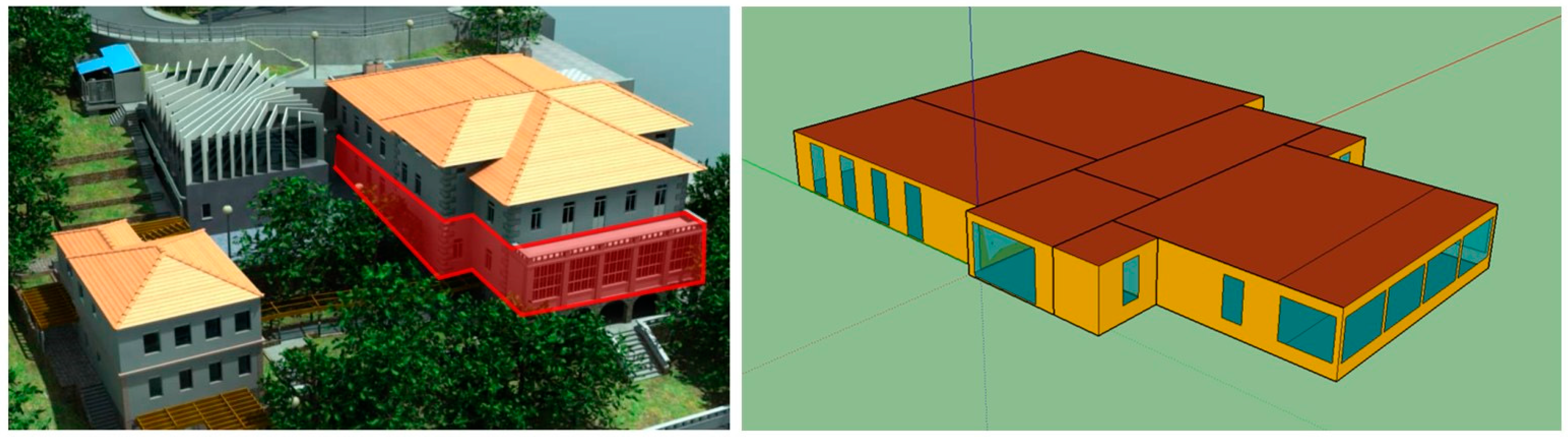
2.3. Case Study—The Building
2.4. Building Energy Systems
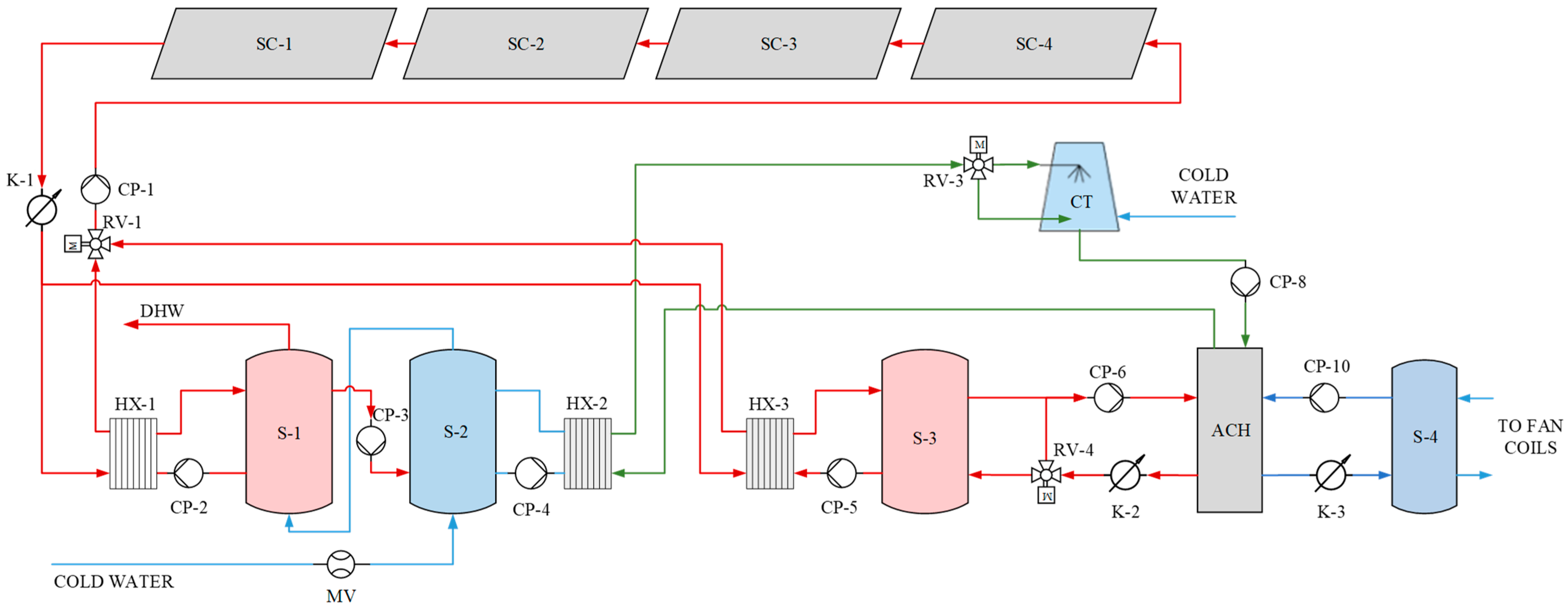
2.4.1. S-FO-ACH-1/S-NG-ACH-1 System
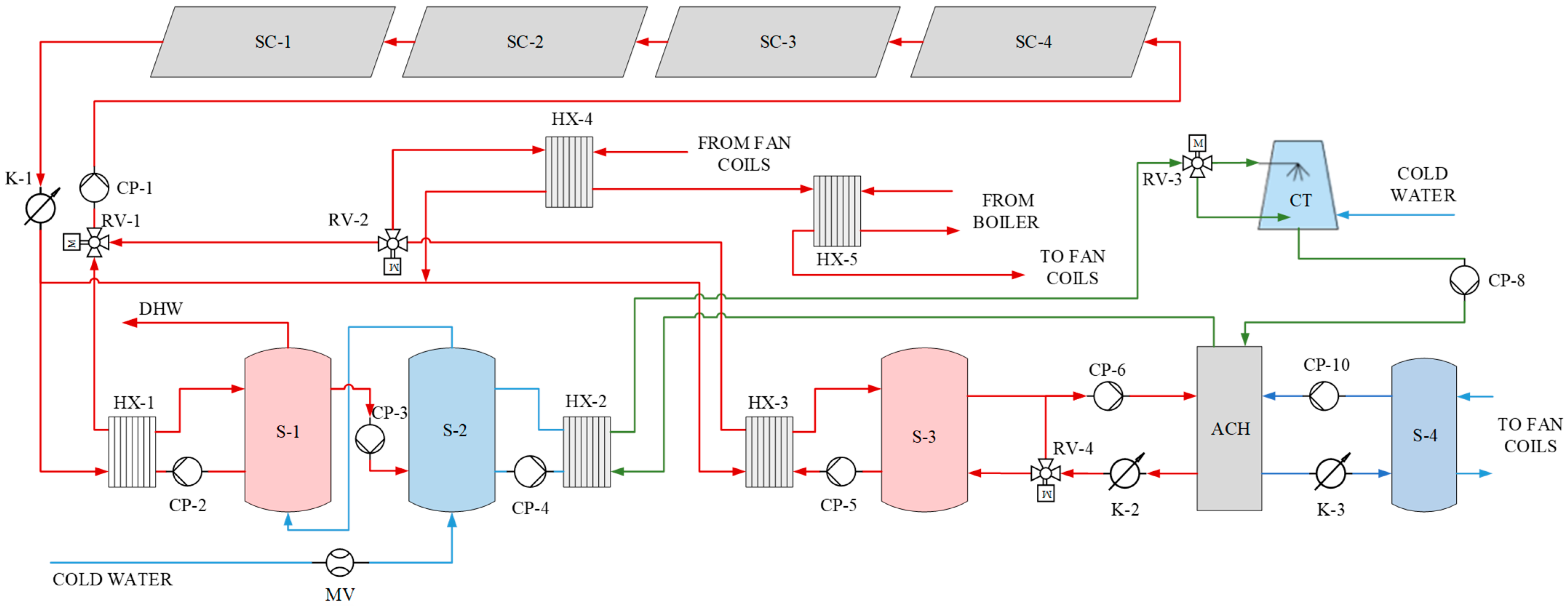
2.4.2. S-FO-ACH-2/S-NG-ACH-2 System
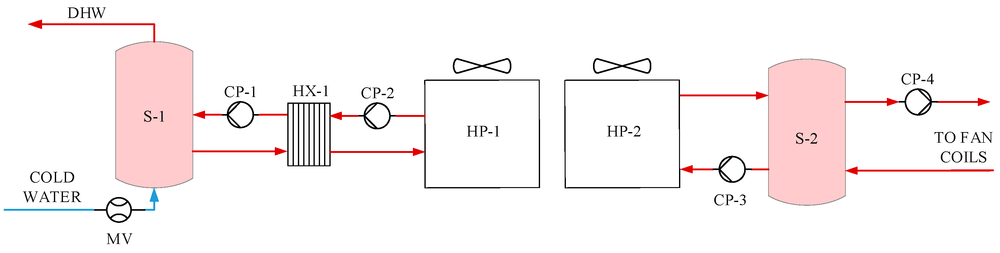
2.4.3. AWHP-1 System
2.4.4. AWHP-2 System
2.5. Costs
2.5.1. Investment Cost
2.5.2. Energy Cost
2.5.3. Maintenance Cost
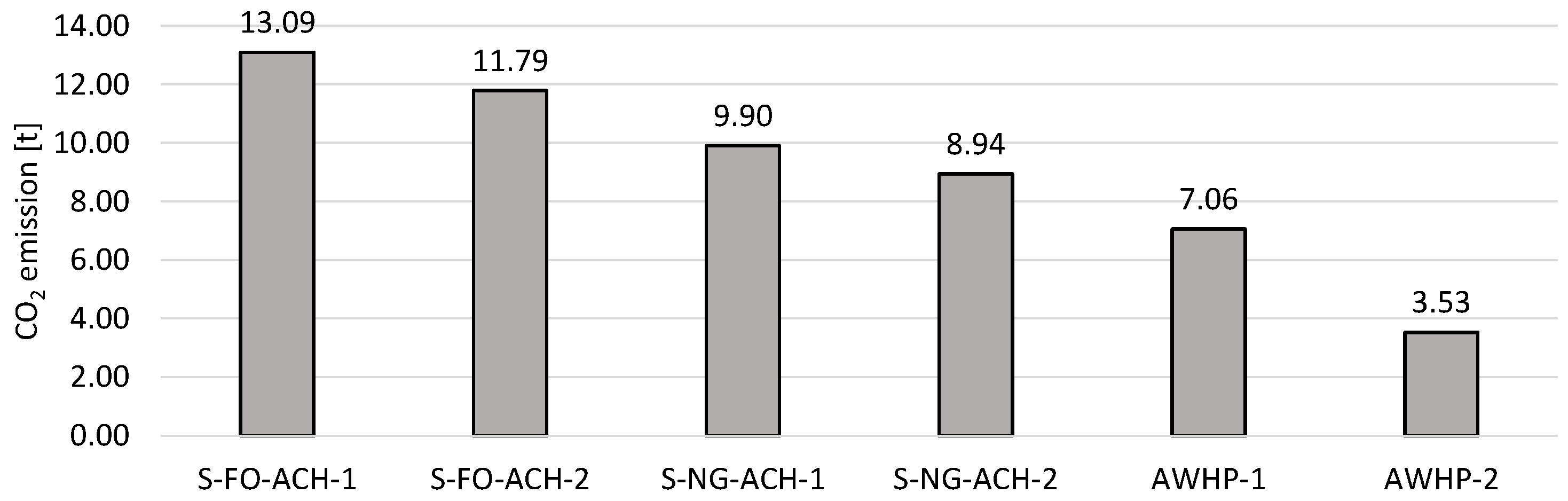
2.6. Primary Energy Consumption and CO2 Emissions
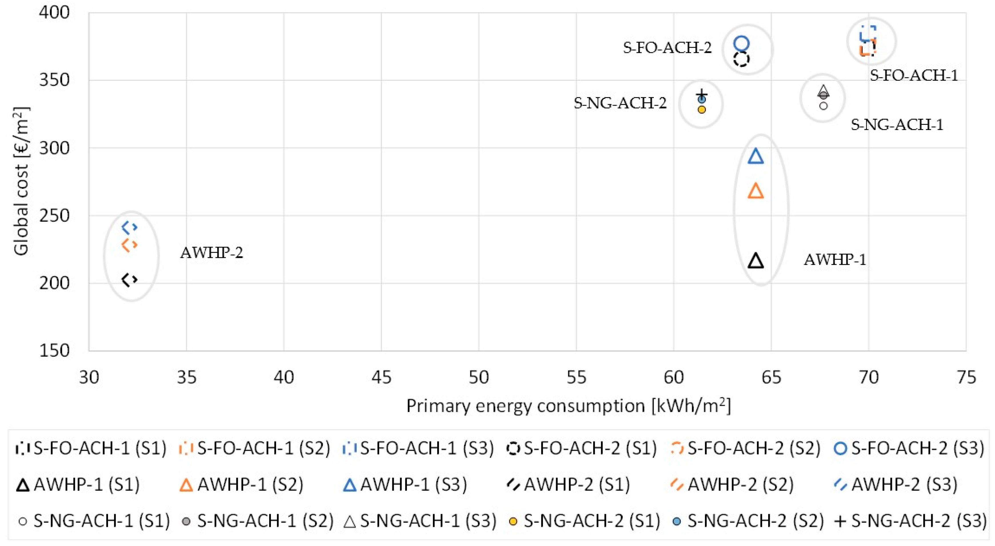
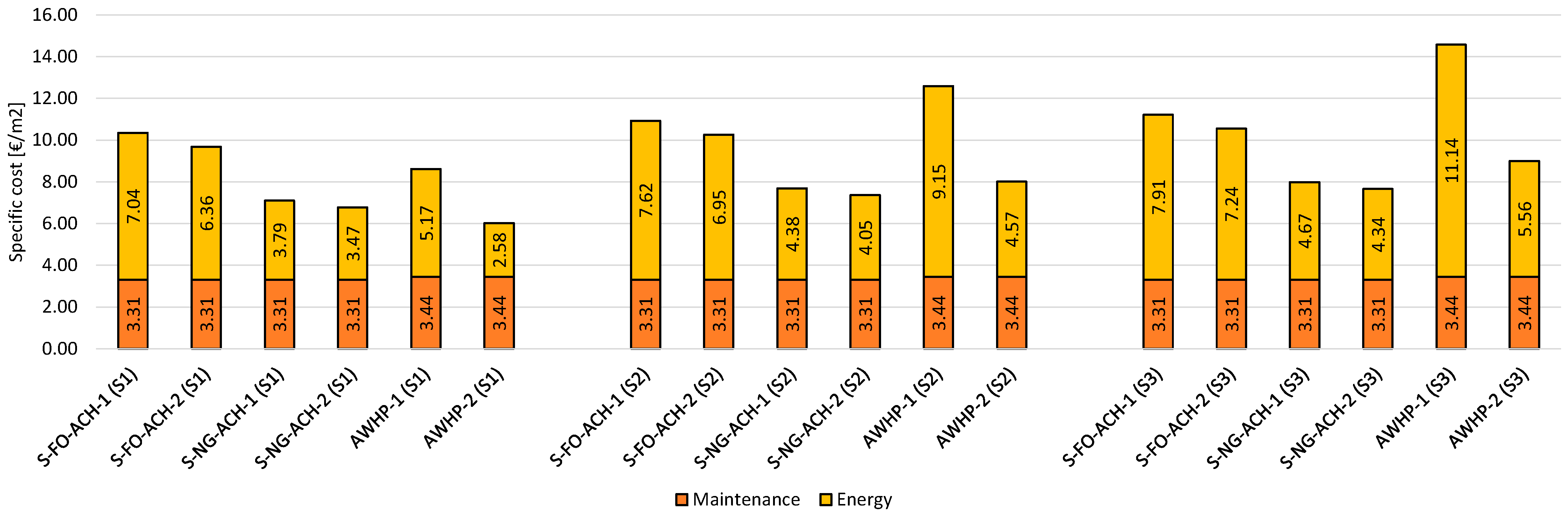
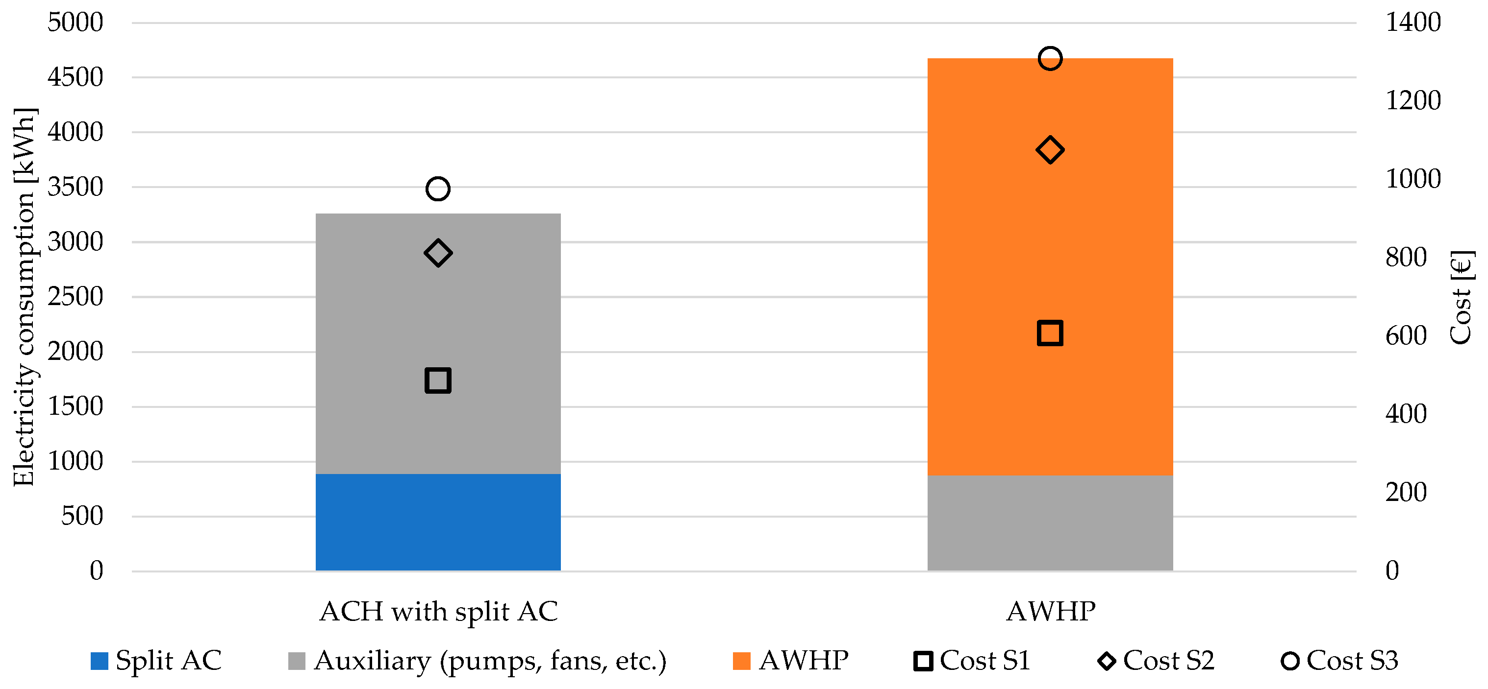
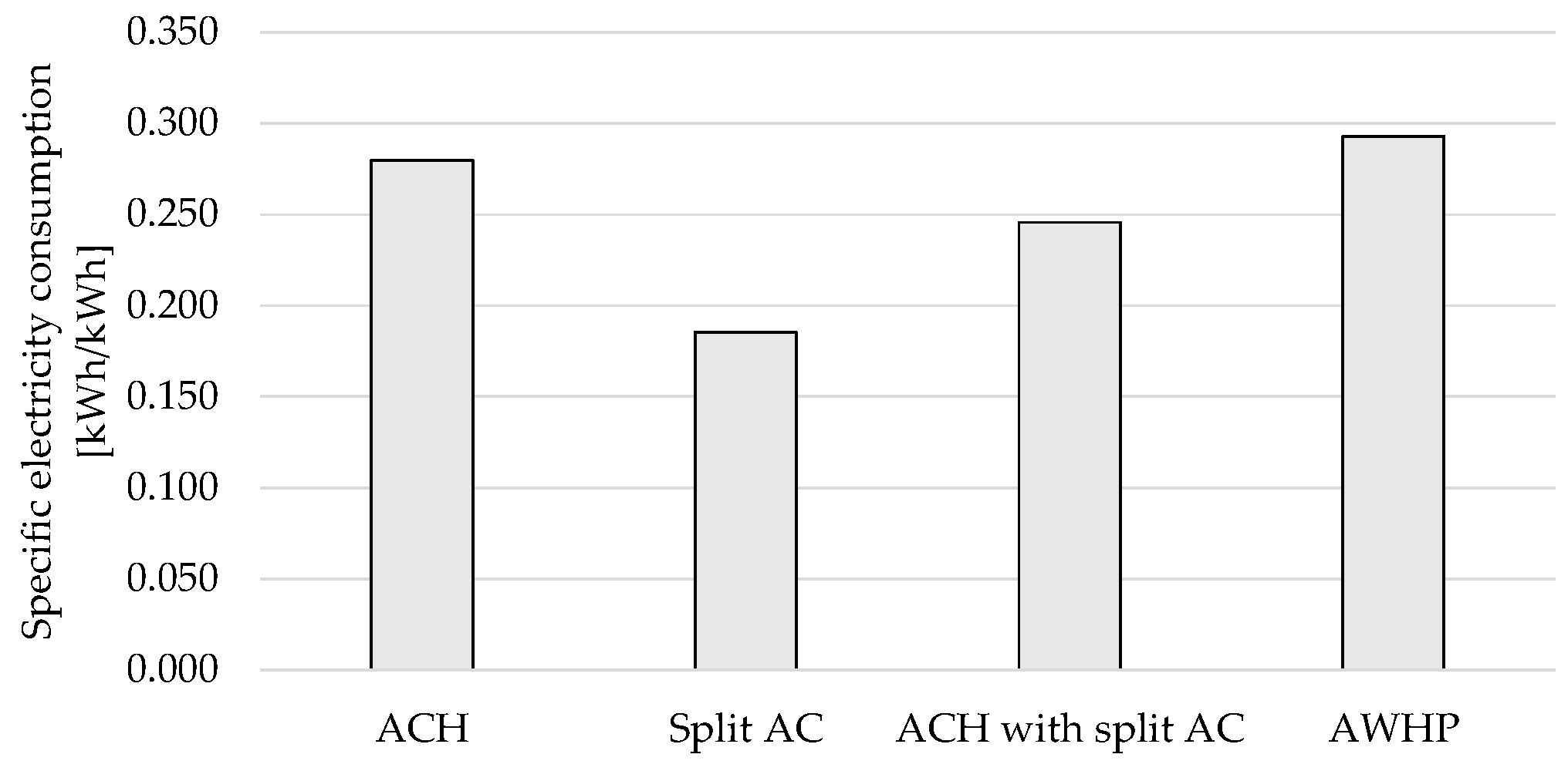
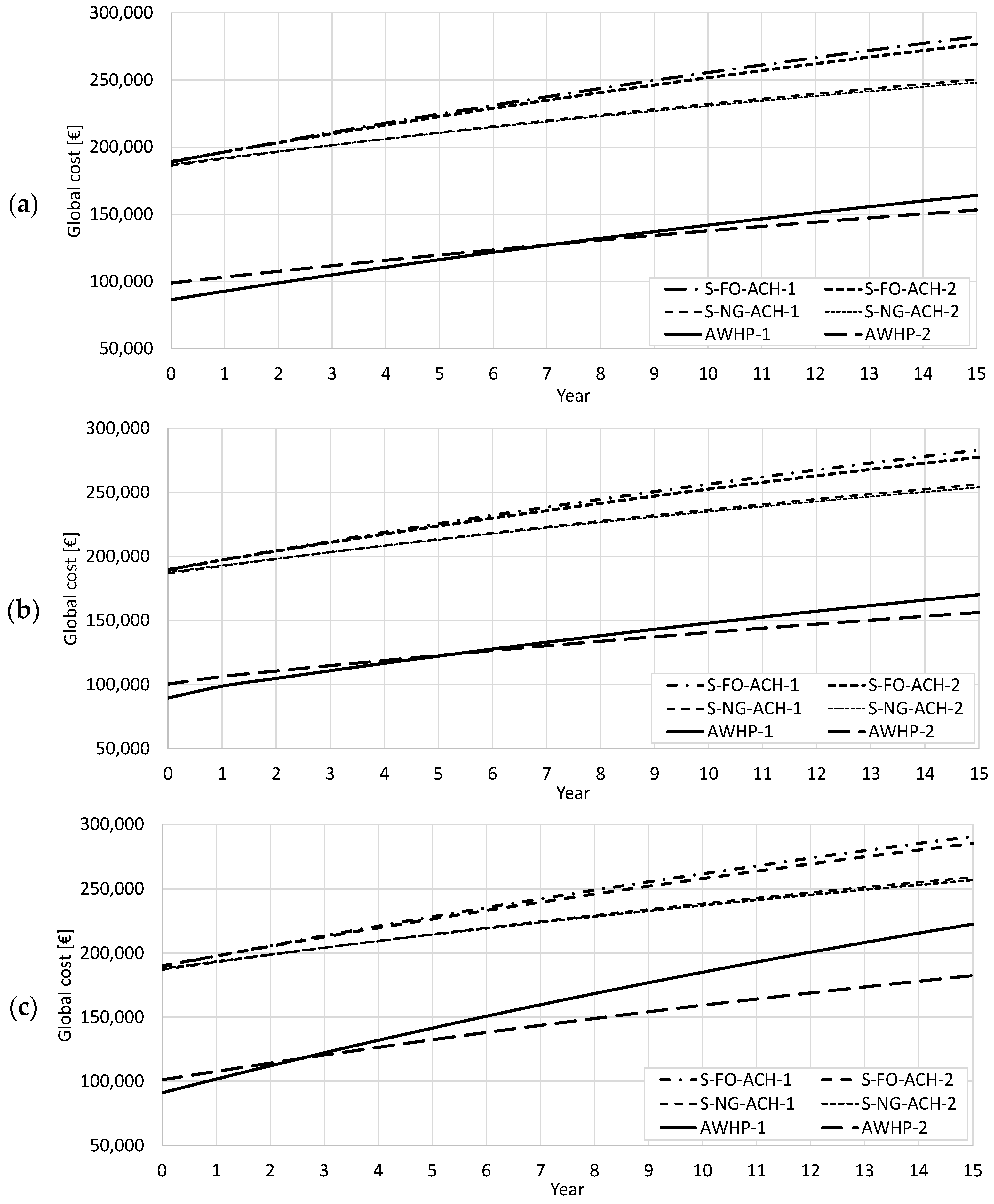
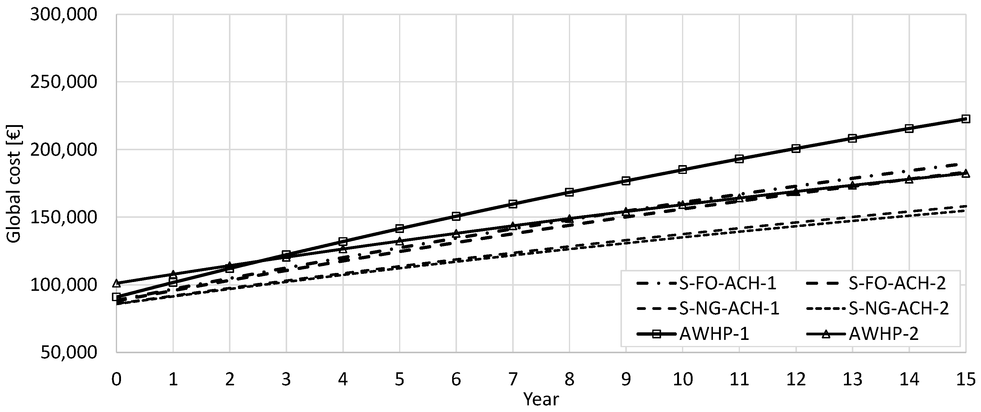
3. Results
4. Conclusions
Author Contributions
Funding
Data Availability Statement
Conflicts of Interest
Nomenclature
| A | area (m2) |
| ACF | absorption cooling fraction (-) |
| ACH | absorption chiller |
| C | cooling |
| CI | cost indicator (EUR/m2) |
| cons | consumed |
| E | energy (kWh) |
| ee | electrical energy |
| f | primary energy factor (-) |
| G | cost (EUR) |
| g | global |
| I | investment |
| imp | imported |
| nren | nonrenewable |
| P | primary |
| PEC | primary energy consumption indicator (kWh/m2) |
| prod | produced |
| RES | renewable energy share (-) |
| Rd | discount factor (-) |
| SF | solar fraction (-) |
| SOL | solar |
| Vf,τ | residual value (-) |
| Abbreviations | |
| ACH | absorption chiller |
| AWHP | air-to-water heat pump |
| H/C | heating and cooling |
| PV | photovoltaic |
| STC | solar thermal collectors |
| SHC | solar heating and cooling |
| TRY | test reference year |
References
- Solar Heat Markets in Europe. 2022. Available online: http://solarheateurope.eu/publications/market-statistics/solar-heat-markets-in-europe/ (accessed on 15 December 2022).
- Solar Heat Markets in Europe. 2021. Available online: http://solarheateurope.eu/project/solar-thermal-markets-in-europe-trends-and-market-statistics-2021-published-in-february-2022// (accessed on 15 December 2022).
- ESTIE. Solar Thermal Markets in Europe—Trends and Market Statistics 2015. 2016. Available online: http://solarheateurope.eu/2016/11/01/solar-thermal-markets-europe-trends-market-statistics-2015-published-november-2016/ (accessed on 15 December 2022).
- IEA. Space Cooling. 2022. Available online: https://www.iea.org/reports/space-cooling (accessed on 11 January 2023).
- SHC Annual Report. 2018. Available online: https://shc.amegroups.com/announcement/view/128 (accessed on 15 December 2022).
- Bellos, E.; Tzivanidis, C.; Antonopoulos, K. Exergetic, energetic and financial evaluation of a solar driven absorption cooling system with various collector types. Appl. Therm. Eng. 2016, 102, 749–759. [Google Scholar] [CrossRef]
- Mateus, T.; Oliveira, A. Energy and economic analysis of an integrated solar absorption cooling and heating system in different building types and climates. Appl. Energy 2009, 86, 949–957. [Google Scholar] [CrossRef]
- Eicker, U.; Pietruschka, D. Design and performance of solar powered absorption cooling systems in office buildings. Energy Build. 2009, 41, 81–91. [Google Scholar] [CrossRef]
- Hang, Y.; Qu, M.; Zhao, F. Economical and environmental assessment of an optimized solar cooling system for a medium-sized benchmark office building in Los Angeles, California. Renew. Energy 2011, 36, 648–658. [Google Scholar] [CrossRef]
- Calise, F.; Palombo, A.; Vanoli, L. Maximization of primary energy savings of solar heating and cooling systems by transient simulations and computer design of experiments. Appl. Energy 2010, 87, 524–540. [Google Scholar] [CrossRef]
- Shirazi, A.; Taylor, R.; White, S.; Morrison, G. Transient simulation and parametric study of solar-assisted heating and cooling absorption systems: An energetic, economic and environmental (3E) assessment. Renew. Energy 2016, 86, 955–971. [Google Scholar] [CrossRef]
- Eicker, U.; Pietruschka, D.; Pesch, R. Heat rejection and primary energy efficiency of solar driven absorption cooling systems. Int. J. Refrig. 2012, 35, 729–738. [Google Scholar] [CrossRef]
- Calise, F. Thermoeconomic analysis and optimization of high efficiency solar heating and cooling systems for different Italian school buildings and climates. Energy Build. 2010, 42, 992–1003. [Google Scholar] [CrossRef]
- Florides, G.; Kalogirou, S.; Tassou, S.; Wrobel, L. Modelling and simulation of an absorption solar cooling system for Cyprus. Sol. Energy 2002, 72, 43–51. [Google Scholar] [CrossRef]
- Florides, G.; Kalogirou, S.; Tassou, S.; Wrobel, L. Modelling, simulation and warming impact assessment of a domestic-size absorption solar cooling system. Appl. Therm. Eng. 2002, 22, 1313–1325. [Google Scholar] [CrossRef]
- Arsalis, A.; Alexandrou, A. Parametric study and cost analysis of a solar-heating-and-cooling system for detached single-family households in hot climate. Sol. Energy 2015, 117, 59–73. [Google Scholar] [CrossRef]
- Tsoutsos, T.; Aloumpi, E.; Gkouskos, Z.; Karagiorgas, M. Design of a solar absorption cooling system in a Greek hospital. Energy Build. 2010, 42, 265–272. [Google Scholar] [CrossRef]
- Eicker, U.; Pietruschka, D.; Haag, M.; Schmitt, A. Systematic design and analysis of solar thermal cooling systems in different climates. Renew. Energy 2015, 80, 827–836. [Google Scholar] [CrossRef]
- Ma, Y.; Saha, S.; Miller, W.; Guan, L. Comparison of Different Solar-Assisted Air Conditioning Systems for Australian Office Buildings. Energies 2017, 10, 1463. [Google Scholar] [CrossRef] [Green Version]
- Huang, L.; Zheng, R.; Piontek, U. Installation and Operation of a Solar Cooling and Heating System Incorporated with Air-Source Heat Pumps. Energies 2019, 12, 996. [Google Scholar] [CrossRef] [Green Version]
- Figaj, R.; Żołądek, M. Operation and Performance Assessment of a Hybrid Solar Heating and Cooling System for Different Configurations and Climatic Conditions. Energies 2021, 14, 1142. [Google Scholar] [CrossRef]
- Kaneesamkandi, Z.; Almujahid, A.; Salim, B. Selection of an Appropriate Solar Thermal Technology for Solar Vapor Absorption Cooling—An MADM Approach. Energies 2022, 15, 1882. [Google Scholar] [CrossRef]
- Lazzarin, R.; Noro, M.; Zanni, O. Solar thermal and ground source absorption heat pump: Energy analysis for a nearly Zero Energy Building. In Proceedings of the 25th IIR International Congress of Refrigeration, Montréal, Canada, 24–30 August 2019; p. 8. [Google Scholar] [CrossRef]
- Energy in Croatia—Annual Energy Report 2019. 2020. Available online: https://mingor.gov.hr/UserDocsImages/UPRAVA%20ZA%20ENERGETIKU/Energija_u_Hrvatskoj/Energija_u_Hrvatskoj_2019-2.pdf/ (accessed on 15 December 2022).
- Eurostat (European Statistical Office). 2022. Available online: https://ec.europa.eu/eurostat (accessed on 26 January 2022).
- Soldo, V.; Novak, S.; Horvat, I. Algorithm for Calculating the Energy Required for Heating and Cooling Building Space According to HRN EN ISO 13790; University of Zagreb, Faculty of Engineering: Zagreb, Croatia, 2017. [Google Scholar]
- Meteonorm. Meteonorm—Global Meteorological Databa; Meteotest: Bern, Switzerland, 2012. [Google Scholar]
- Technical Regulation on Rational Use of Energy and Thermal Protection in Buildings, Croatia. 2015. Available online: https://narodne-novine.nn.hr/clanci/sluzbeni/dodatni/438515.pdf (accessed on 15 December 2022).
- EN 12831; Energy Performance of Buildings—Method for Calculation of the Design Heat Load. BSI Standards: Brussels, Belgium, 2017.
- Richtlinie VDI 2078 Blatt 1 Berechnung der Kühllast klimatisierter Gebäude bei Raumkühlung über Raumumschließungsflächen; Bauphysik: Berlin, Germany, 2003. [CrossRef]
- Recknagel, E.; Sprenger, H.; Schramek, E.-R. Taschenbuch fur Heizung und Klimatechnik; Oldenbourg Industrieverlag: Munchen, Germany, 2007. [Google Scholar]
- Delač, B. Optimization of Energy Systems for Nearly Zero Energy Buildings Using Dynamic Simulations; Faculty of Engineering, University of Rijeka: Rijeka, Croatia, 2017. [Google Scholar]
- Commission Delegated Regulation No 244/2012. 2012. Available online: http://www.buildup.eu/sites/default/files/content/l_08120120321en00180036.pdf (accessed on 15 December 2022).
- Guidelines Accompanying Commission Delegated Regulation (EU) No 244/2012 of 16 January 2012 Supplementing Directive 2010/31/EU of the European Parliament and of the Council (2012/C 115/01); EU: Brussels, Belgium, 2012.


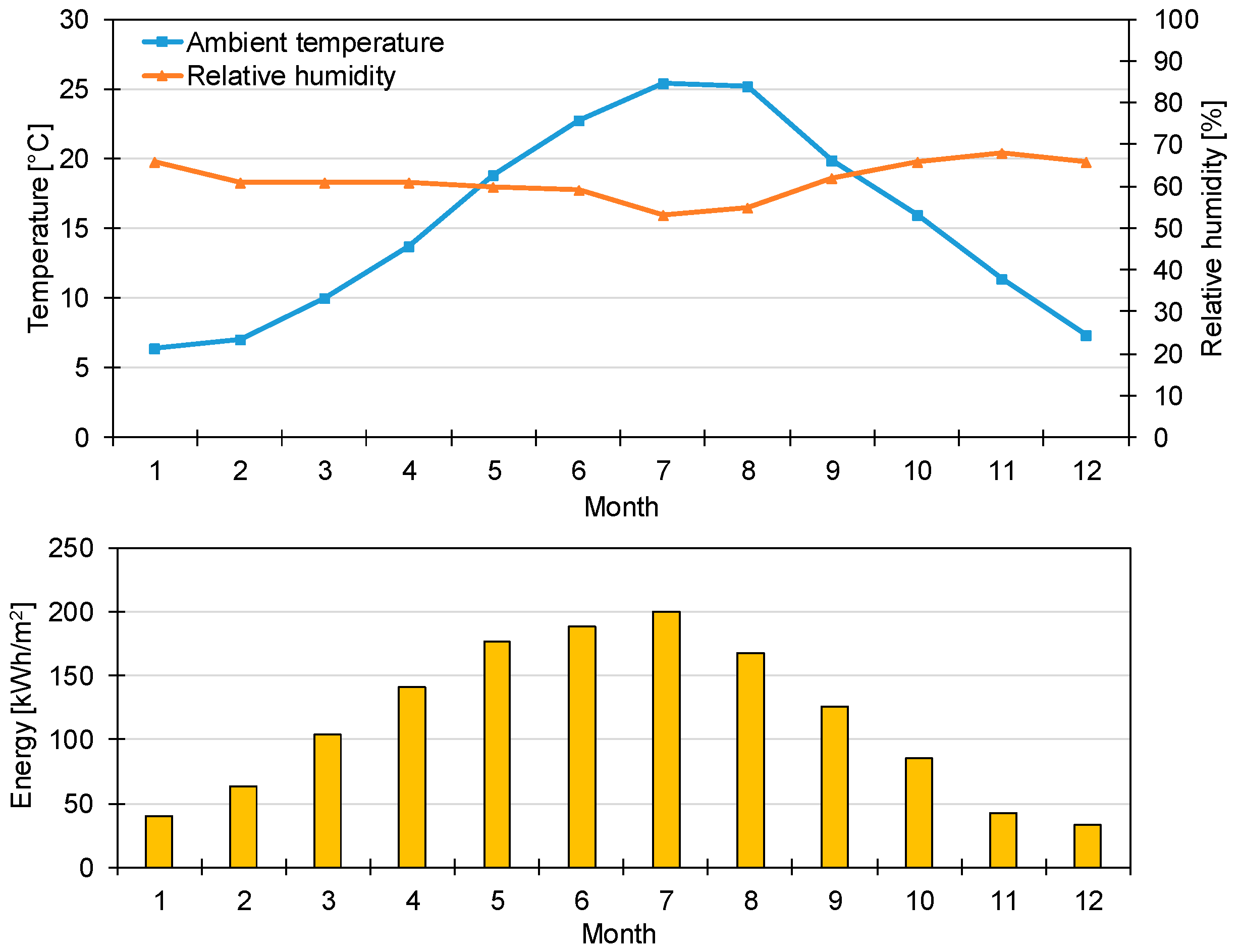
| Climate data | City | Crikvenica (Croatia) |
| Longitude | 14.6915 E | |
| Latitude | 45.1736° N | |
| Physics | Dimensions (length x width x height) | 36 × 21 × 3.2 m |
| Conditioned area | 756 m2 | |
| Conditioned volume | 2419 m3 | |
| Envelope | External wall U-value | 0.85 W/m2 K |
| Internal wall U-value | 0.9 W/m2 K | |
| Ceiling/floor towards the building U-value | 0.75 W/m2 K | |
| Floor on the ground U-value | 1.93 W/m2 K | |
| Window/door U-value | 2.9 W/m2 K | |
| Ventilation | Infiltration/required ventilation rate | 0.42 h−1/5.62 h−1 |
| Mechanical ventilation | Not existing | |
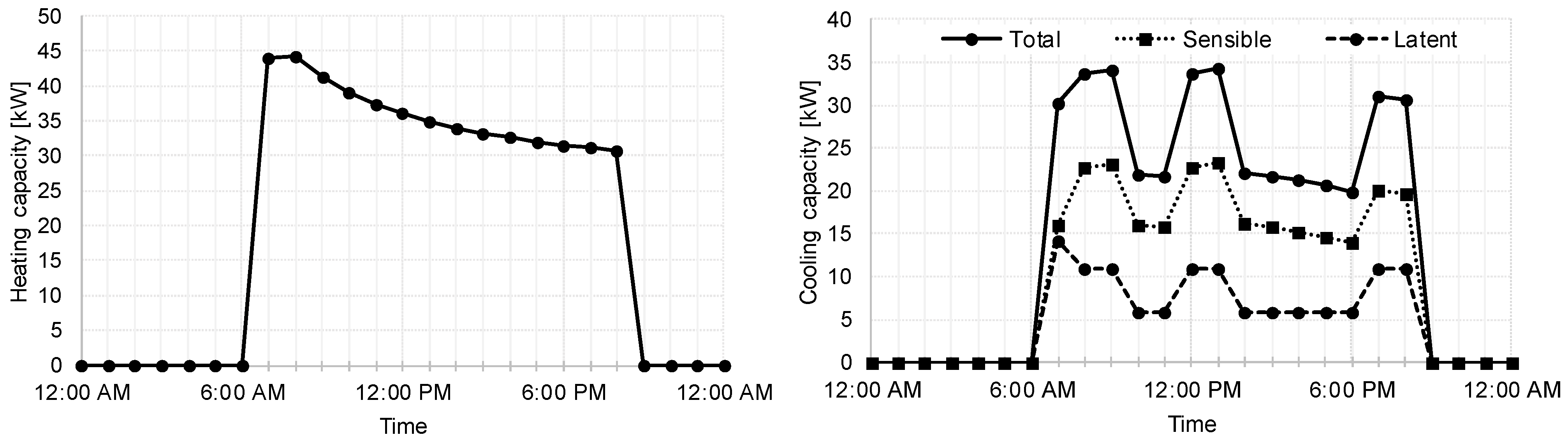
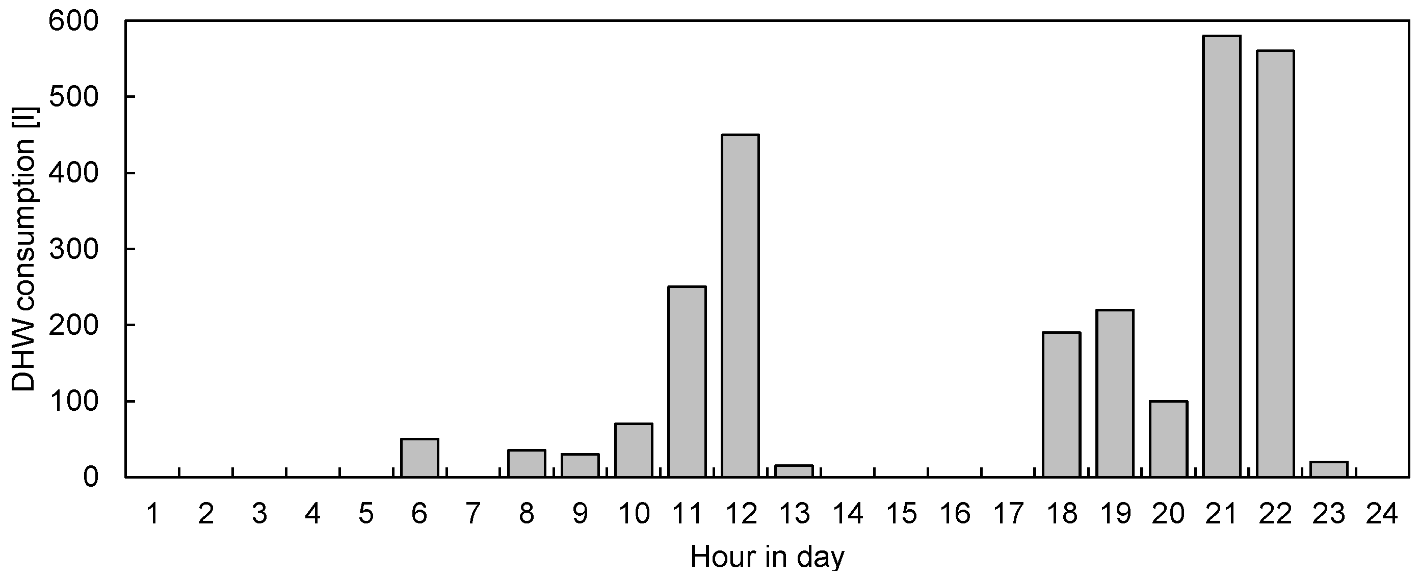
| Occupancy and operation | Occupancy | 7 days in a week 8–10 AM 12 AM–2 PM 6 PM–9 PM |
| Number of persons | 200 persons | |
| Internal heat gains | 6 W/m2 | |
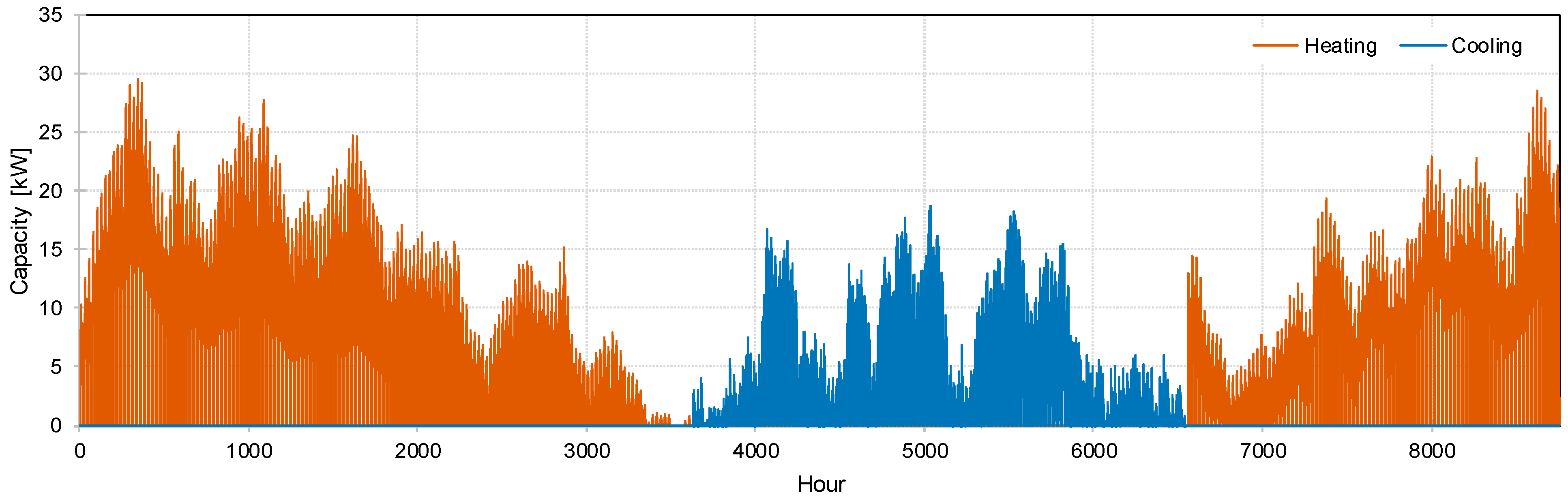
| Heating and cooling operation | Interrupted 7 AM–9 PM | |
| Heating temperature set point | 22 °C | |
| Cooling temperature set point | 24 °C | |
| DHW set point | 45 °C |
| System | Building Heating | Building Cooling | DHW Heating | Electricity Production |
|---|---|---|---|---|
| S-FO-ACH-1 | Fuel oil boiler | ACH * Split AC * | Fuel oil boiler STC * | - |
| S-FO-ACH-2 | Fuel oil boiler STC * | ACH * Split AC * | Fuel oil boiler STC * | - |
| S-NG-ACH-1 | Natural gas boiler | ACH * Split AC * | Natural gas boiler STC * | - |
| S-NG-ACH-2 | Natural gas boiler STC * | ACH * Split AC * | Natural gas boiler STC * | - |
| AWHP-1 | AWHP * | AWHP * | - | |
| AWHP-2 | AWHP * | AWHP * | PV | |
| System | Description | Price |
|---|---|---|
| S-FO-ACH-1 or S-NG-ACH-1 | Solar thermal collectors, pipeline, pumps, valves, fittings, supporting construction | 57,000 EUR |
| Absorption chiller, storage tanks, cooling tower, heat exchanger, pipeline, pumps, valves, fittings | 66,000 EUR | |
| DHW storage tanks, heat exchangers, pipeline, pumps, valves, fittings | 15,000 EUR | |
| Automation and wiring | 43,000 EUR | |
| Total | 181,000 EUR | |
| S-FO-ACH-2 or S-NG-ACH-2 | Solar thermal collectors, pipeline, pumps, valves, supporting construction, additional heat exchanger | 58,000 EUR |
| Absorption cooling: chiller, storage tanks, cooling tower, heat exchanger, pipeline, pumps, valves, fittings | 66,000 EUR | |
| DHW storage tanks, heat exchangers, pumps, valves, fittings | 15,000 EUR | |
| Automation and wiring | 43,000 EUR | |
| Total | 182,000 EUR | |
| AWHP-1 | Air-to-water heat pump for heating and cooling, inertial storage tank, pipeline, pump, valves and fittings | 35,000 EUR |
| Air-to-water heat pump for DHW heating, DHW storage tank, heat exchanger, pumps, valves, fittings | 25,000 EUR | |
| Automation and wiring | 20,000 EUR | |
| Total | 80,000 EUR | |
| AWHP—2 | Air-to-water heat pump for heating and cooling, inertial storage tank, pipeline, pump, valves and fittings | 35,000 EUR |
| Air-to-water heat pump for DHW heating, DHW storage tank, heat exchanger, pumps, valves, fittings | 25,000 EUR | |
| Automation and wiring | 20,000 EUR | |
| PV plant (18 kW) | 14,400 EUR | |
| Total | 94,400 EUR |
| Energy Carrier | Cost | Price | |
|---|---|---|---|
| Electricity | Scenario S1 | 0.13 | EUR/kWh |
| Scenario S2 | 0.23 | EUR/kWh | |
| Scenario S3 | 0.28 | EUR/kWh | |
| Fuel oil | 0.118 | EUR/kWh | |
| Natural gas | 0.057 | EUR/kWh | |
| Water | 2.7 | EUR/m3 |
| Energy Source | Value | Unit | |
|---|---|---|---|
| Electricity | Primary energy factor | 1.614 | - |
| CO2 emission factor | 0.2348 | kg/kWh | |
| Fuel oil | Primary energy factor | 1.138 | - |
| CO2 emission factor | 0.2995 | kg/kWh | |
| Natural gas | Primary energy factor | 1.095 | - |
| CO2 emission factor | 0.2202 | kg/kWh |
| System | Description | Value | Unit | |
|---|---|---|---|---|
| S-FO-ACH-1 or S-NG-ACH-1 | Produced energy for heating | Fuel oil/gas boiler | 31,472 | kWh |
| Produced energy for cooling | Absorption chiller | 8467 | kWh | |
| Split type air conditioners | 4790 | kWh | ||
| Produced energy for DHW heating | Solar collectors | 24,232 | kWh | |
| Waste heat from ACH | 4080 | kWh | ||
| Fuel oil/gas boiler | 4786 | kWh | ||
| Irradiation at solar collectors | 81,307 | kWh | ||
| Fuel oil/gas consumption | 40,287 | kWh | ||
| Electricity consumption | 4369 | kWh | ||
| ACF (absorption cooling fraction) | 0.64 | (-) | ||
| SFDHW (solar fraction for DHW) | 0.73 | (-) | ||
| RES (renewable energy share) | 0.42 | (-) | ||
| S-FO-ACH-2 or S-NG-ACH-2 | Produced energy for heating | Fuel oil/gas boiler | 22,277 | kWh |
| Solar collectors | 9694 | kWh | ||
| Produced energy for cooling | Absorption chiller | 8466 | kWh | |
| Split-type air conditioners | 4793 | kWh | ||
| Produced energy for DHW heating | Solar collectors | 14,936 | kWh | |
| Fuel oil/gas boiler | 10,037 | kWh | ||
| Waste heat from ACH | 4077 | kWh | ||
| Irradiation at solar collectors | 81,307 | kWh | ||
| Fuel oil/gas consumption | 35,905 | kWh | ||
| Electricity consumption | 4419 | kWh | ||
| ACF (absorption cooling fraction) | 0.64 | (-) | ||
| SFH (solar fraction for building heating) | 0.30 | (-) | ||
| SFDHW (solar fraction for DHW heating) | 0.51 | (-) | ||
| RES (renewable energy share) | 0.45 | (-) | ||
| AWHP-1 | Produced energy for heating | 32,441 | kWh | |
| Produced energy for cooling | 12,956 | kWh | ||
| Produced energy for DHW heating | 32,104 | kWh | ||
| Electricity consumption | Heat pump (building heating) | 12,920 | kWh | |
| Heat pump (building cooling) | 3797 | kWh | ||
| Heat pump (DHW heating) | 9024 | kWh | ||
| Auxiliary (pumps) | 4333 | kWh | ||
| RES (renewable energy share) | 0.59 | (-) | ||
| AWHP-2 | * HVAC system energy production, consumption and performance is the same as for AWHP-1 system | |||
| Electricity from PV | 15,057 | kWh | ||
| Electricity from grid | 15,018 | kWh | ||
| RES (renewable energy share) | 0.79 | (-) | ||
Disclaimer/Publisher’s Note: The statements, opinions and data contained in all publications are solely those of the individual author(s) and contributor(s) and not of MDPI and/or the editor(s). MDPI and/or the editor(s) disclaim responsibility for any injury to people or property resulting from any ideas, methods, instructions or products referred to in the content. |
© 2023 by the authors. Licensee MDPI, Basel, Switzerland. This article is an open access article distributed under the terms and conditions of the Creative Commons Attribution (CC BY) license (https://creativecommons.org/licenses/by/4.0/).
Share and Cite
Delač, B.; Pavković, B.; Glažar, V. Economic and Energetic Assessment and Comparison of Solar Heating and Cooling Systems. Energies 2023, 16, 1241. https://doi.org/10.3390/en16031241
Delač B, Pavković B, Glažar V. Economic and Energetic Assessment and Comparison of Solar Heating and Cooling Systems. Energies. 2023; 16(3):1241. https://doi.org/10.3390/en16031241
Chicago/Turabian StyleDelač, Boris, Branimir Pavković, and Vladimir Glažar. 2023. "Economic and Energetic Assessment and Comparison of Solar Heating and Cooling Systems" Energies 16, no. 3: 1241. https://doi.org/10.3390/en16031241