Article

An Adaptive-Gain Sliding Mode Observer with Precise Compensation for Sensorless Control of PMSM

1
Electric Power Research Institute of State Grid Gansu Electric Power Company, Lanzhou 730070, China
2
College of Electrical Engineering, Sichuan University, Chengdu 610065, China
*
Author to whom correspondence should be addressed.
Energies 2023, 16(24), 7968; https://doi.org/10.3390/en16247968
Submission received: 21 October 2023 / Revised: 26 November 2023 / Accepted: 6 December 2023 / Published: 8 December 2023
(This article belongs to the Section F3: Power Electronics)

Abstract

:
In this paper, we propose a sensorless control strategy for permanent magnet synchronous motors (PMSMs) based on an adaptive-gain sliding mode observer (ASMO) with precise compensation. Firstly, the observer adopts a saturation function with a continuous boundary layer as the switching function to avoid the delay effect of the low-pass filter. In addition, the adaptive-gain method is designed based on a conventional sliding mode observer (SMO) with constant-gain and a saturation function. The adaptive-gain mathematical model is simplified by establishing a nonlinear feedback channel of an SMO. Secondly, in order to improve the practicability and facilitate debugging, the explicit stability condition of an ASMO is deduced according to Lyapunov’s second method. According to the proposed adaptive method, the chattering caused by the mismatch of the sliding-mode gain is suppressed, and the observable speed range is also improved. Thirdly, the position estimation delay problem of an SMO with a continuous switching function is analyzed in detail from the perspective of frequency characteristics. Then, a precise compensation method is proposed for the delay problem, which greatly improves the position estimation accuracy and the control performance. Finally, the correctness of the theory and the feasibility of the ASMO with precise compensation for the sensorless control of PMSMs are verified by experiments.

1. Introduction

With the rapid development of permanent magnet materials, permanent magnet synchronous motors (PMSMs) have gradually entered people’s lives. PMSMs are widely used in transportation, national defense, agricultural production, industrial manufacturing, and many other fields, with the advantages of having a simple structure, high reliability, high power density, and easy control [1,2]. The control system of a PMSM often adopts the vector control strategy. The traditional methods employ the position sensor to provide precise rotor position and speed information for the control system. However, the existence of a position sensor not only greatly increases the cost of the control system, but also has the disadvantages of poor reliability, inconvenient installation, and an inability to be used in harsh working conditions [3]. In order to solve these problems, scholars have carried out a lot of research on sensorless control technology.
At present, sensorless control technology is mainly divided into two categories. One is the low-speed range method based on the saliency effect [4,5,6], which uses the externally injected excitation signal to obtain the rotor position and speed information. One of the main drawbacks of this approach is that complex signal processing is required in both the extraction and estimation of high-frequency currents [7]. Another type is the high-speed range method based on back electromotive force (BEMF) [8,9] or flux linkage [10,11]. This type of method requires the use of an observer to obtain the BEMF or flux linkage which carry the position information of the rotor, and the estimation accuracy is greatly affected by the rotational speed. Commonly used observation methods include the Lomborg observer method, the extended Kalman filter method, the sliding mode observer (SMO) method, and so on [12,13,14,15,16,17]. The SMO method has been widely used in the field of sensorless control because of its strong robustness, fast response speed, and easy engineering implementation.
The accuracy of the SMO is mainly determined by the deviation and chattering of the estimation results. In [18], the switching characteristics of the SMO make the estimated BEMF contain a large number of harmonic components, resulting in serious chattering, so a low-pass filter (LPF) is introduced. However, the delay effect of the LPF causes deviation in the rotor position estimation, which deteriorates the performance of the observer. Therefore, some scholars proposed to replace LPF with other filters to avoid LPF delay, for example, the adaptive second-order generalized integrator proposed by [19] and the synchronous frequency-extract filter proposed by [20]. However, this type of scheme relies on the fast and precise tracking of the fundamental frequency of BEMF, otherwise the phase delay will be increased, so the dynamic performance and reliability are poor. In this case, it is valuable to study SMO without filters, and higher-order sliding modes are seen as a viable option due to their low chattering properties. In [21,22], a high-order terminal SMO and a high-order SMO based on the super-twisting algorithm were used to obtain the rotor position and speed, respectively. This kind of high-order sliding mode scheme sets the sign function in the integral term of the control rate to ensure the continuity of the first derivative of the sliding mode surface, so as to achieve the purpose of effectively suppressing chattering at the root. However, this causes serious damage to the structure of the observer, making it overly complicated. Therefore, the more widely used strategy is to adopt a continuous function with a boundary layer (BL) instead of a discontinuous sign function as the switching function. In [23,24,25,26], the saturation function, the hyperbolic tangent function, and the sigmoid function have all been shown to reduce chattering.
Based on the above research results, Ref. [27] introduced an adaptive SMO for the problem that the constant sliding-mode gain cannot cope with the chattering suppression ability at low speed and the stability at high speed. This method improves the estimation accuracy of the observer over a wide speed range. In [28], an adaptive second-order SMO was employed to suppress the undesired chattering at low speeds by adjusting the sliding mode coefficients online. The adaptive gain will make the original stability condition no longer applicable, but the above articles do not theoretically derive a clear stability condition, and they do not consider the influence of the adaptive-gain on the position estimation accuracy.
In practical applications, changes or mismatches of motor parameters may also cause the deviation of observation results. In [29,30,31], parameter identification technologies were applied to the field of sensorless technology to improve observer accuracy and system robustness. In addition, limited by the operation speed of the digital signal processor, the rotor position estimation result always lags behind the actual position. Considering this problem, Ref. [32] proposed a current compensation method based on the dual-sampling technique, which was used to estimate the actual current at the current moment, suppressing the delay of the position estimation. The above research all focuses on the estimation deviation caused by external factors, and there are few studies on the estimation error of the algorithm itself. In [33], the continuous switching function of SMO exhibits a delay characteristic in position estimation, which means that the contradiction between the chattering and deviation of the observer remains unresolved. Therefore, the full compensation of this position estimate deviation is achieved by constructing a nonlinear equivalent model. However, the accuracy of this model has high requirements on the range of motor stator resistance, and its application is limited.
The main innovative work of this paper is to propose an adaptive-gain sliding mode observer (ASMO) that considers estimation deviation. The adaptive strategy is proposed to suppress position chattering in the wide speed range, which improves the speed observation range. Furthermore, the ASMO is simplified as a nonlinear feedback channel, and then the equivalent model of the adaptive-gain strategy is obtained. The Lyapunov function is constructed according to the equivalent model, and the precise stability conditions of the ASMO are deduced. In addition, the compensation method of position estimation deviation is proposed by analyzing the delay effect of an SMO with saturation function, which significantly improves the estimation accuracy of the sliding mode observer.

2. Conventional SMO

2.1. Mathematical Model of PMSM

The mathematical model of a PMSM in the α-β stationary reference frame can be expressed as the following form:
d i α d t = R S L S i α + u α L S e α L S d i β d t = R S L S i β + u β L S e β L S
where RS and LS represent the resistance and inductance of the stator winding, respectively; iα, iβ, uα, uβ, and eα, eβ are the stator current, stator voltage, and BEMF in the α-β coordinate system, respectively.
The BEMF of PMSM in a fixed reference frame is given by
e α = ω r ψ f sin θ r = E sin θ r e β = ω r ψ f cos θ r = E cos θ r
where θr, ωr, ψf, and E are the rotor electrical angle, rotor electrical angular velocity, permanent-magnet flux linkage, and amplitude of BEMF, respectively.

2.2. Conventional SMO with Constant Gain and Saturation Function

Based on the PMSM mathematical model shown in (1), the stator current observer can be constructed. The conventional SMO is designed as
d i ^ α d t = R S L S i ^ α + u α L S k f ( i ˜ α ) L S d i ^ β d t = R S L S i ^ β + u β L S k f ( i ˜ β ) L S
where i ^ α and i ^ β represent the estimated value of the current in the α-β-axis. i ˜ α and i ˜ β are estimated current errors, defined as i ˜ α = i ^ α i α , i ˜ β = i ^ β i β . f ( ) and k are the switching function and sliding-mode gain of the SMO, respectively.
According to the introduction, the continuous function has become the most common switching function of a conventional SMO instead of the sign function. The various continuous functions chosen in [23,24,25,26] exhibit properties similar to saturation functions. Therefore, in order to make the research in this paper more general, the most representative saturation function is used as the switching function, namely
f ( x ) = 1 x a x a a < x < a 1 x a
where a is a constant used to adjust the thickness of the BL.
Figure 1 shows the structure of the above conventional SMO (the conventional SMO in this paper is the SMO with a constant gain and saturation function). The observation gain must be large enough to ensure that the SMO reaches the sliding mode. So, the value of k needs to satisfy the following inequality conditions:
k max ( e α , e β ) .
Based on the equivalent control principle of SMO, the estimated BEMF can be obtained from (3)
e ^ α = k f ( i ˜ α ) e ^ β = k f ( i ˜ β ) .
Compared with the SMO based on the sign function, although the above SMO no longer needs LPFs, there are still two conspicuous problems to be solved.
(1)
The limitation of the observable speed range caused by constant gain: The most prominent problem with constant gain is that it cannot meet the needs of a wide speed range. If the gain is too large, it will cause severe chattering at low speeds. If the gain is too small, the stability condition cannot be satisfied at high speeds, and the SMO cannot work normally.
(2)
The delay problem caused by the continuous switching function: Using a continuous function as the switching function will inevitably cause a certain phase delay, especially at high speeds. This is unfavorable for realizing high-precision sensorless control.
Consequently, it is valuable to develop an SMO with high accuracy over a wide speed range. This part of the content will be introduced in detail in the next sections (Section 3 and Section 4)

3. Improved SMO with Adaptive-Gain

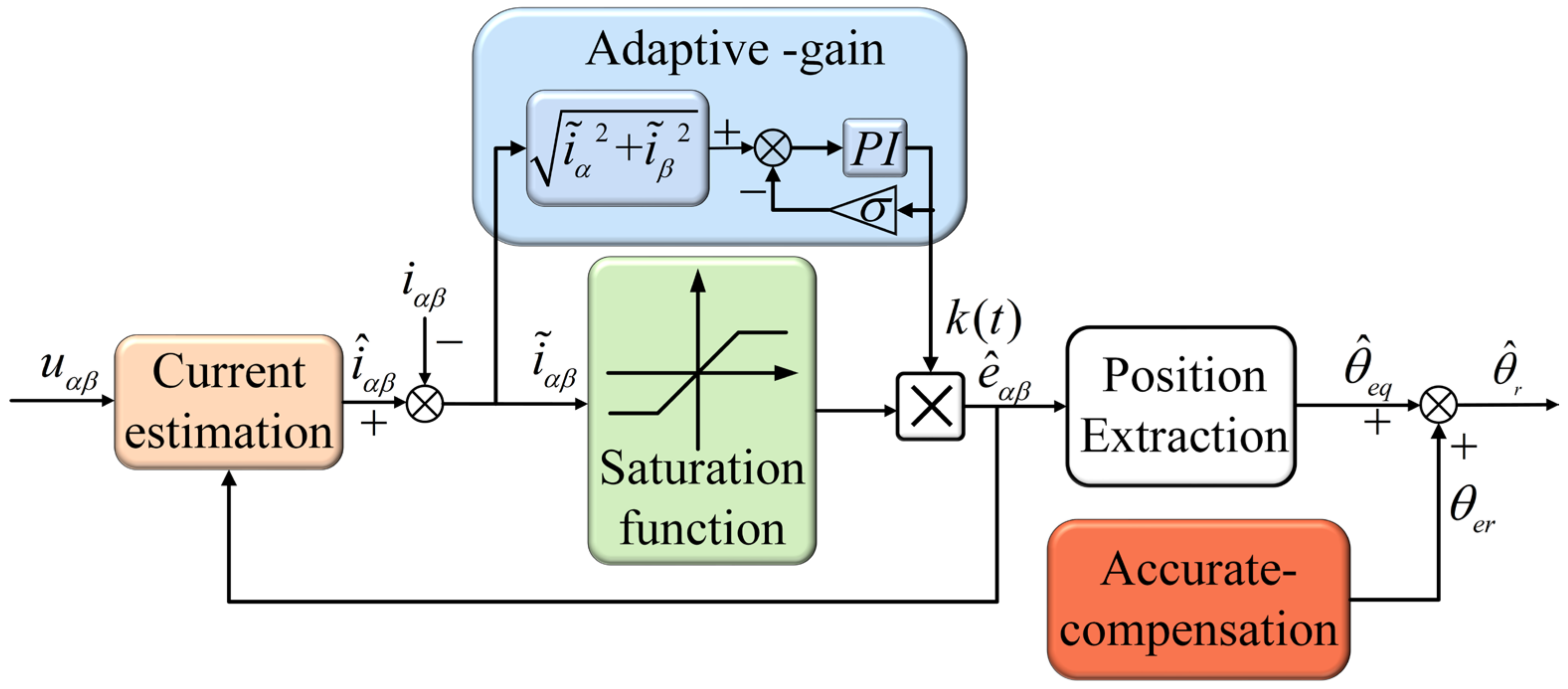
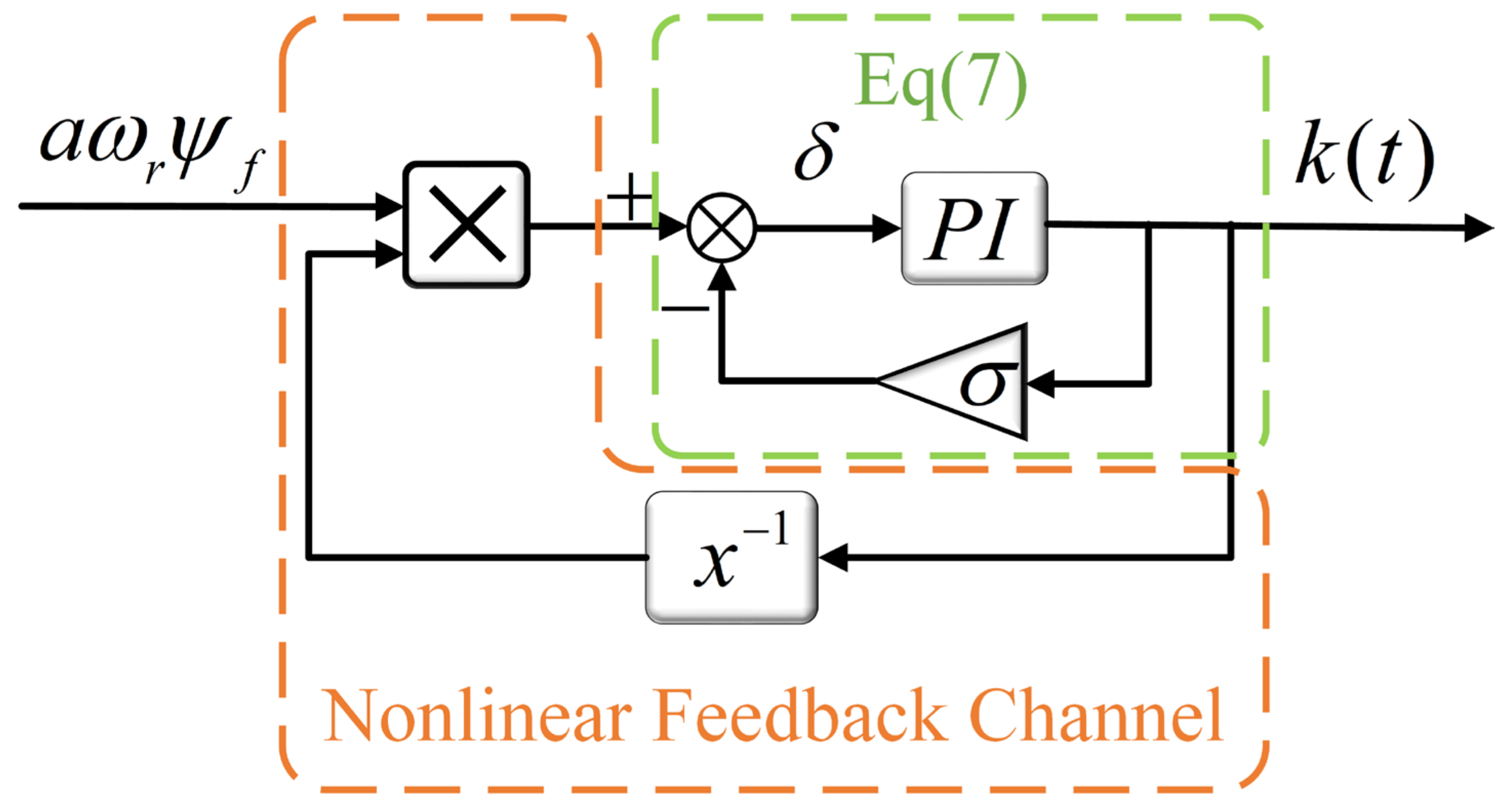
3.1. Adaptive-Gain SMO

The estimated current errors i ˜ α and i ˜ β are crucial parameters of an SMO, which can characterize the suppression degree of chattering. When the system is stable, the BEMF obtained by the observer will be clamped, and the SMO can provide a nonlinear feedback channel for the adaptive-gain. Based on this idea, this paper proposes a novel observer with an adaptive-gain strategy with PI regulation. This strategy can be described as follows:
δ = i ˜ α 2 + i ˜ β 2 σ k ( t ) k ( t ) = K p δ + K i δ d t .
where Kp and Ki are the proportional and integral coefficients of the adaptive law, respectively. These two parameters determine the bandwidth of the adaptive-gain. A larger bandwidth will make the system have a faster response speed, but it will also introduce more harmonic noise of the BEMF obtained by the SMO. In addition, Ki should be large enough to ensure that δ converges to zero, otherwise it will lead to uncertainty in the stability conditions. σ is the feedback coefficient, which is a positive constant, used to adjust the size of k(t), and its value range should meet the stability conditions (20) derived later.
Substitute k(t) for the constant-gain k in (3) to obtain ASMO:
d i ^ α d t = R S L S i ^ α + u α L S k ( t ) f ( i ˜ α ) L S d i ^ β d t = R S L S i ^ β + u β L S k ( t ) f ( i ˜ β ) L S .
The structure diagram of ASMO is shown in Figure 2. Subtracting (1) from (8), the dynamic error for the stator current can be written as follows:
d i ˜ α d t = R S L S i ˜ α + e α L S k ( t ) f ( i ˜ α ) L S d i ˜ β d t = R S L S i ˜ β + e β L S k ( t ) f ( i ˜ β ) L S .
Define the estimated current error as a sliding surface:
S = S α S β = i ^ α i α i ^ β i β = 0
.
When the motion state of the system enters the sliding mode, the estimated BEMF is expressed as follows:
e ^ α = k ( t ) f ( i ˜ α ) e ^ β = k ( t ) f ( i ˜ β ) .
Due to the existence of nonlinear feedback channels, there are the following relations:
i ˜ α 2 + i ˜ β 2 = a ω r ψ f k ( t ) .
Substitute (12) into (7), the equivalent model of adaptive-gain can be obtained, as shown in Figure 3.
δ = a ω r ψ f k ( t ) σ k ( t ) k ( t ) = K p δ + K i δ d t .
The amplitude of the BEMF is determined by the parameters of the motor and the speed of the rotor, and is independent of the design of the observer. So, it can be regarded as the input of the equivalent model. With this equivalent model, precise stability conditions of ASMO can be derived, which will be analyzed in detail below.

3.2. Stability Analysis of ASMO

An ASMO does not require the artificial selection of the value of the sliding-mode gain, so the stability conditions of the traditional SMO are no longer applicable. Therefore, the stability of the ASMO was reappraised.
In this paper, Lyapunov’s second method is used to obtain the stability condition of an ASMO. According to the sliding-mode variable structure theory and the equivalent model of adaptive-gain, the Lyapunov function is defined as follows:
V = 1 2 S T S p a r t 1 + 1 2 ( a ω r ψ f k ( t ) σ k ( t ) ) 2 p a r t 2
where part 2 is used to ensure that δ can converge. Obviously, V is positive and definite. According to Lyapunov’s theory, just proving that V · is negative and definite can show that the system is stable and the state variable converges to the vicinity of zero. The time derivative of (14) is shown as follows:
V ·   = S T S · + ( a ω r ψ f k ( t ) σ k ( t ) ) ( a ω r ψ f k ( t ) 2 σ ) k · ( t )
Substitute (13) into (15)
V · = S T S · ( a ω r ψ f k ( t ) σ k ( t ) ) ( a ω r ψ f k ( t ) 2 + σ ) K p k · ( t ) ( a ω r ψ f k ( t ) 2   σ   ) + K i ( a ω r ψ f k ( t ) σ k ( t ) ) .
From (15) and (16), it can be deduced that
( a ω r ψ f k ( t ) 2 σ ) k · ( t ) = K i ( a ω r ψ f k ( t ) σ k ( t ) ) ( a ω r ψ f k ( t ) 2 + σ ) K p ( a ω r ψ f k ( t ) 2 + σ ) + 1 .
According to (9), (10), and (17), (15) can be rewritten as follows:
V · = 1 L S ( e α k ( t ) f ( i ˜ α ) ) i ˜ α + ( e β k ( t ) f ( i ˜ β ) ) i ˜ β p a r t 1 + R S L S ( i ˜ 2 α + i ˜ 2 β ) p a r t 2 + K i ( a ω r ψ f k ( t ) σ k ( t ) ) 2 ( a ω r ψ f k ( t ) 2 + σ ) K p ( a ω r ψ f k ( t ) 2 + σ ) + 1 p a r t 3 .
Obviously, part 2 of (18) is less than zero, the denominator of part 3 is greater than zero, and the numerator is less than zero, so it is not difficult to conclude that part 3 is also less than zero. Therefore, δ will approach zero after a period of transient time, which indicates that
k ( t ) = a σ max ( e α , e β ) .
To make V · < 0 , part 1 should also meet the condition of being no greater than zero, so it can be derived that the observer gain also satisfies the following inequality conditions:
k ( t ) max ( e α , e β )
Combining (19) and (20), the final stable condition of the ASMO can be obtained as follows:
a σ max ( e α , e β ) .
It can be seen from (21) that the stability of the proposed ASMO is jointly determined by a and σ, which is quite different from the traditional stability condition (5). Since the amplitude of BEMF is proportional to the rotor electrical angular velocity when selecting the parameters, it is necessary to reserve a sufficient stability margin to ensure the stability of the observer in a wide speed range.

3.3. Position and Speed Extraction

BEMF-based sensorless control techniques are suitable for calculating rotor position using arctangent functions, such as
θ ^ eq = arctan ( e ^ α e ^ β ) .
Then, the speed is obtained by the time derivative of the position angle
ω ^ r = d θ ^ eq d t .
Nevertheless, the harmonics in BEMF may be amplified by division and differentiation operations, which will cause undesired chattering. PLL has a good suppression effect on high-frequency noise, so it is widely used for rotor position tracking in sensorless control technology. Figure 4 is a block diagram of a common second-order PLL, which is mainly composed of a phase detector (PD), a loop filter (LF), and a voltage-controlled oscillator (VCO). The calculation formula of the speed and rotor position is shown as follows:
ε = sin ( θ θ ^ eq ) θ θ ^ eq ω ^ r = k p ε + k i ε d t θ ^ eq = ω ^ r d t
where kp, ki are positive constants and ε is the normalized angle error. Extraction of rotor speed and position through PLL can further eliminate chattering.

4. Delay Effect Analysis and Precise Compensation

As mentioned above, the method of choosing continuous functions as the switching function can avoid the delay of the LPF, but this will bring a new delay to the rotor position calculation, which is not conducive to improving the performance of the observer. Consequently, it is extremely necessary to eliminate the lag of the observation phase to achieve high-precision sensorless control. In this section, the mechanism of position estimation delay is studied in detail, and the corresponding compensation for this delay is refined.

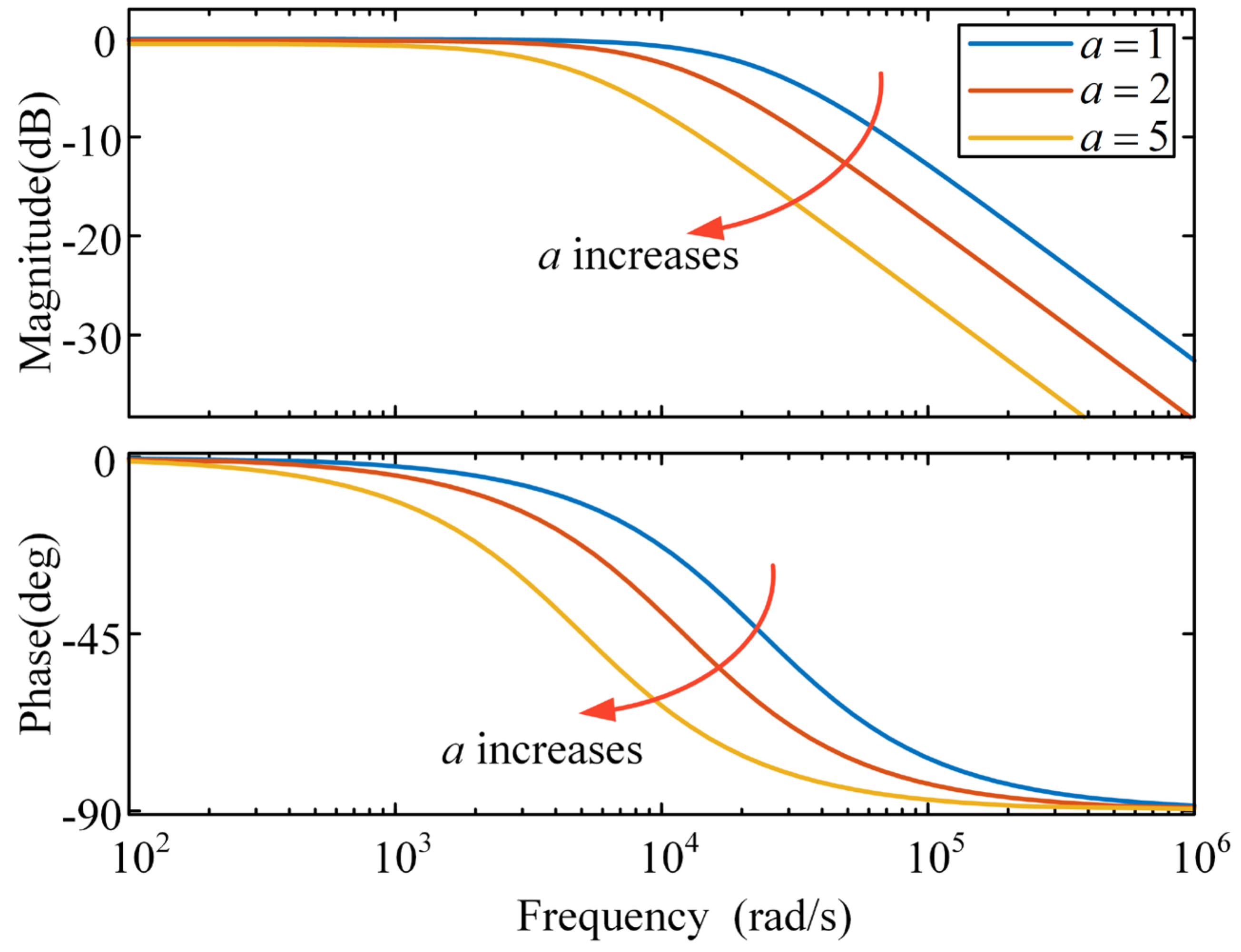
4.1. Delay Effect Analysis

Once the system meets the stability conditions, the amplitude of the estimated current error will be limited within the boundary layer, so (4) can be rewritten as follows:
f ( i ˜ α ) f ( i ˜ β ) = η i ˜ α η i ˜ β
where η is the slope in the BL, η = 1/a.
Substituting (25) into (9), the new current dynamic error can be described as
d i ˜ α d t = R S + k ( t ) η L S i ˜ α e α L S d i ˜ β d t = R S + k ( t ) η L S i ˜ β e β L S .
From (11) and (25), it can be obtained that the estimated BEMF is equal to k ( t ) η i ˜ α , β . Therefore, after the Laplace transform is performed on (26), the relationship between the estimated BEMF and the actual BEMF is shown as follows:
e ^ α = μ γ s + μ e α e ^ β = μ γ s + μ e β
Where μ = (RS + ηk(t))/LS, γ = R/LS, and μ >> γ. The bode diagram corresponding to (27) is shown in Figure 5. It is not difficult to see from the bode diagram that the SMO actually exhibits characteristics similar to LPF. The cut-off frequency mainly depends on the parameters a and k(t), which are actually the slopes in the BL. Take parameter a as an example. As a increases and the cut-off frequency decreases, the better the suppression effect on chattering and the greater the delay. All in all, the delay of the position estimation comes from the low-pass filter characteristics of the SMO, and the compensation calculation for the delay angle is shown below.

4.2. Compensation Calculation

Substitute (2) into (26) and solve the differential equation as follows:
i ˜ α = ( c α ω r ν μ 2 + ω r 2 ) e μ t ν ( μ ) 2 + ω r 2 sin ( θ r θ e r ) i ˜ β = ( c β μ ν μ 2 + ω r 2 ) e μ t p a r t 1 + ν μ 2 + ω r 2 cos ( θ r θ e r ) p a r t 2 .
where cα, cβ are constants. It can be seen that the current error consists of two parts, part 1 is the transient component of fast decay, which can be ignored, so BEMF can be expressed as follows:
e ^ α = k ( t ) η i ˜ α = ν k ( t ) η μ 2 + ω r 2 sin ( θ r θ e r ) e ^ β = k ( t ) η i ˜ β = ν k ( t ) η μ 2 + ω r 2 cos ( θ r θ e r )
where ν = ωrψf/LS. Since μ >> ωr and ηk(t) >> RS, (28) can be simplified as follows:
e ^ α = ω r ψ f sin ( θ r θ e r ) = E sin ( θ r θ e r ) e ^ β = ω r ψ f cos ( θ r θ e r ) = E cos ( θ r θ e r )
where θer is the lag angle of the estimated BEMF, given by the following:
θ e r = arctan ( L S ω r R S + k ( t ) η ) .
The position information θ ^ eq obtained by the estimated BEMF is equal to θ r θ e r . Therefore, the actual rotor position should be
θ ^ r = θ ^ eq + θ e r .
By using the method proposed in this paper, rotor position information without delay can be obtained while ensuring the effective suppression of chattering, and the contradiction between chattering suppression and position accuracy can be solved.

5. Experimental Results

The superiority and feasibility of the proposed ASMO are verified by experiments. The vector control strategy with id = 0 is used in the experiments, and the second-order PLL is used to extract rotor speed and position information. Figure 6 is a block diagram of the sensorless control system based on an ASMO, where the superscript * represents the reference value. The experiment was carried out on a 4 kW Surface-mounted PMSM and the motor parameters are shown in Table 1. The experimental algorithm was realized using the digital signal processor TMS320F28335, and the motor was driven by the inverter circuit composed of the insulated gate bipolar transistor module SKM75GB12T4. The switching frequency of the inverter was 10 kHz, and the DC bus voltage was powered by a high-power programmable DC power supply produced by ITECH. All calculated waveforms were generated by digital-to-analog converters (DAC) and acquired using an oscilloscope. The waveforms of speed and position angle used for comparison were detected by an incremental encoder. It is worth noting that the dead time of the inverter was set to 0.6 us during the experimental process, and the nonlinearity of the inverter introduced additional harmonics in the BEMF, which could be suppressed through inverter nonlinearity compensation [26] and some other filters [19,20].
(1) Steady-state performance: The steady-state performance tests of a conventional SMO, and the ASMO with precise compensation proposed in this paper, at 500 rpm are shown in Figure 7. It can be seen that, since the ASMO has a more suitable sliding-mode gain than the conventional SMO, it has higher accuracy in the estimation of speed. Furthermore, the uncompensated rotor position estimation error reaches 0.06 rad, while the compensated position error can be kept around zero. It can also be seen from the waveform of the rotor position that the estimated value and the actual value waveform almost completely overlap after compensation. Benefiting from the higher rotor position accuracy, the q-axis current is reduced from 4.2 A to 4.12 A after adopting the proposed ASMO, as shown in Figure 7e,f.
For a more comprehensive analysis of the performance of the proposed method, the speed was increased to 1000 rpm and a steady-state experiment was performed again, as shown in Figure 8. Compared to Figure 7, it can be found that the speed estimation error of the conventional SMO is reduced, while the proposed ASMO has almost no change and maintains high accuracy. This is because the sliding-mode gain of the conventional SMO is set in consideration of high-speed occasions, but the adaptive-gain can cope with different speeds. In addition, as the speed increases, the estimation accuracy of the strategy without compensation decreases, and the position estimation error exceeds 0.1 rad, but the accuracy of the compensation method is hardly affected by the speed. Moreover, the difference between the q-axis current of the two methods is increased from 0.08 A to 0.22 A, which can improve the efficiency of the machine. According to these two steady-state experiments, it can be proved that the proposed improved algorithm has a better steady-state performance.
(2) Dynamic performance: Figure 9 shows a comparative experiment of the influence on the observer’s rotor speed and position estimation when the reference speed is stepped from 300 rpm to 600 rpm. When the speed is changed, the sliding-mode gain of the ASMO adaptively changes with the change in speed, as shown in Figure 9b. Meanwhile, the phenomenon in the steady-state part is the same as that of the steady-state experiment, and the description will not be repeated below. In the transient part, the speed estimation error of the conventional SMO increases to nearly 60 rpm, while the maximum position estimation error reaches 0.16 rad. The ASMO with precise compensation showed a better dynamic performance, and its speed estimation error was less than 40 rpm. In addition, it can be seen from Figure 9f that, since the value of the position compensation will be dynamically adjusted with the speed change, the position estimation error only increases to 0.1 rad and, after a period of time, it recovers to a level close to zero. This demonstrates that the proposed scheme has a higher accuracy in the transient process and can ensure the accuracy of the position information in the actual working conditions with frequent speed changes.
In order to further verify the dynamic performance of the proposed strategy, the deceleration comparison experiment shown in Figure 10 was carried out. The reference speed was reduced from 1100 rpm to 100 rpm. As the speed decreased, the position estimation error of the conventional SMO gradually decreased from 0.165 rad. When the speed decreased to about 200 rpm, the speed and position estimation with the conventional SMO appeared as violent chattering in Figure 10a,c. As shown in Figure 10c, when the speed was reduced to 100 rpm, the speed error with the conventional SMO reached 100 rpm. According to (23), it can be seen that the rotor position is derived from the integral of the speed, and the integral has a certain filtering effect, so the fluctuation of the position error is not as large as that of the speed estimation error. But even so, the amplitude of the chattering was close to 0.5 rad and the waveform of the position angle was severely distorted, as shown in the waveform at the top of the figure. In this case, the motor can only barely run, which means that the observer can no longer replace the position sensor at this time. However, the position estimation of the proposed ASMO with accurate compensation was not affected by the speed change and maintained a high estimation accuracy during the entire deceleration process, as shown in Figure 10b. When the speed was close to 100 rpm, although the speed and position estimation chattering increased, it could still meet the control requirements. The phenomenon of this experiment is completely consistent with the theoretical derivation, which proves that the method proposed in this paper can effectively suppress the position deviation while increasing the speed range.
Finally, the load disturbance performance of an ASMO with accurate compensation is shown in Figure 11. When the speed is 800 rpm, the loads of 4.4 N.m and 8.4 N.m are switched twice at 0.8 s and 3 s, respectively. When the disturbance arrives, the speed will drop or increase by about 60 rpm, but the speed estimation error will never exceed 20 rpm. On the other hand, the position estimation error also remains within 0.1 rad during the transient period. After stabilization, the accuracy of position estimation is almost unaffected by the change in load, and the error of position estimation is negligible. The effectiveness of the ASMO with accurate compensation to cope with load disturbance is verified.

6. Conclusions

In this paper, a novel ASMO with precise compensation for the sensorless control of PMSMs is proposed. The adaptive rate of sliding-mode gain was designed based on the nonlinear feedback channel of an SMO. The stability conditions of the ASMO were obtained using Lyapunov’s second method. Due to the adaptive modulation of sliding-mode gain, the ASMO achieves the effective suppression of chattering at low speeds and ensures stability at high speeds. Secondly, the delay effect of an SMO with a continuous boundary switching function was analyzed, and corresponding compensation schemes were proposed. The experimental results show that, compared to constant gain SMO, the proposed strategy has a wider speed range. In addition, the compensated ASMO has high accuracy in terms of position and speed estimation performance in both dynamic and steady states.
It is worth mentioning that, when other types of continuous functions are used as switching functions, they also exhibit characteristics similar to saturation functions. Therefore, the delay effect analysis in this paper is not limited to an SMO suitable for saturation functions.

Author Contributions

Conceptualization, W.L., Y.Y. and H.N.; methodology, B.L.; software, X.Z.; validation, W.L.; formal analysis, B.L.; investigation, Y.Y.; data curation, W.L. and C.Z.; writing—original draft preparation, B.L.; writing—review and editing, Y.Z.; supervision, W.L., Y.Y., C.Z. and H.N. All authors have read and agreed to the published version of the manuscript.

Funding

This research was funded by the science and technology project of the State Grid Corporation of China (Grant number 52272222001J).

Data Availability Statement

The data are available upon request from the corresponding author.

Acknowledgments

The authors are grateful for the help provided by the School of Electrical Engineering at Sichuan University.

Conflicts of Interest

Authors Wenfei Liu, Yong Yang, Haoming Niu and Xujun Zhang were employed by the State Grid Gansu Electric Power Company. The remaining authors declare that the research was conducted in the absence of any commercial or financial relationships that could be construed as a potential conflict of interest.

References

  1. El-Refaie, A.M. Fractional-slot concentrated-windings synchronous permanent magnet machines: Opportunities and challenges. IEEE Trans. Ind. Electron. 2009, 57, 107–121. [Google Scholar] [CrossRef]
  2. Zhou, Y.; Xue, Z. Analytical method for calculating the magnetic field of spoke-type permanent magnet machines accounting for eccentric magnetic pole. IEEE Trans. Ind. Electron. 2020, 68, 2096–2107. [Google Scholar] [CrossRef]
  3. Pacas, M. Sensorless drives in industrial applications. IEEE Ind. Electron. Mag. 2011, 5, 16–23. [Google Scholar] [CrossRef]
  4. Xu, P.L.; Zhu, Z.Q. Novel carrier signal injection method using zero-sequence voltage for sensorless control of PMSM drives. IEEE Trans. Ind. Electron. 2015, 63, 2053–2061. [Google Scholar] [CrossRef]
  5. Kim, S.; Ha, J.I.; Sul, S.K. PWM switching frequency signal injection sensorless method in IPMSM. IEEE Trans. Ind. Appl. 2012, 48, 1576–1587. [Google Scholar] [CrossRef]
  6. Li, H.; Zhang, X.; Yang, S.; Liu, S. Unified graphical model of high-frequency signal injection methods for PMSM sensorless control. IEEE Trans. Ind. Electron. 2019, 67, 4411–4421. [Google Scholar] [CrossRef]
  7. Repecho, V.; Waqar, J.B.; Biel, D.; Dòria-Cerezo, A. Zero speed sensorless scheme for permanent magnet synchronous machine under decoupled sliding-mode control. IEEE Trans. Ind. Electron. 2021, 69, 1288–1297. [Google Scholar] [CrossRef]
  8. Sreejith, R.; Singh, B. Sensorless predictive current control of PMSM EV drive using DSOGI-FLL based sliding mode observer. IEEE Trans. Ind. Electron. 2020, 68, 5537–5547. [Google Scholar] [CrossRef]
  9. Wang, G.; Ding, L.; Li, Z.; Xu, J.; Zhang, G.; Zhan, H.; Ni, R.; Xu, D. Enhanced position observer using second-order generalized integrator for sensorless interior permanent magnet synchronous motor drives. IEEE Trans. Energy Convers. 2014, 29, 486–495. [Google Scholar]
  10. Zhang, X. Sensorless induction motor drive using indirect vector controller and sliding-mode observer for electric vehicles. IEEE Trans. Veh. Technol. 2013, 62, 3010–3018. [Google Scholar] [CrossRef]
  11. Comanescu, M. Design and implementation of a highly robust sensorless sliding mode observer for the flux magnitude of the induction motor. IEEE Trans. Energy Convers. 2016, 31, 649–657. [Google Scholar] [CrossRef]
  12. Bernard, P.; Praly, L. Estimation of position and resistance of a sensorless PMSM: A nonlinear Luenberger approach for a nonobservable system. IEEE Trans. Autom. Control 2020, 66, 481–496. [Google Scholar] [CrossRef]
  13. Kwon, T.S.; Shin, M.H.; Hyun, D.S. Speed sensorless stator flux-oriented control of induction motor in the field weakening region using Luenberger observer. IEEE Trans. Power Electron. 2005, 20, 864–869. [Google Scholar] [CrossRef]
  14. Yin, Z.; Li, G.; Zhang, Y.; Liu, J.; Sun, X.; Zhong, Y. A speed and flux observer of induction motor based on extended Kalman filter and Markov chain. IEEE Trans. Power Electron. 2016, 32, 7096–7117. [Google Scholar] [CrossRef]
  15. Cao, R.; Jiang, N.; Lu, M. Sensorless control of linear flux-switching permanent magnet motor based on extended Kalman filter. IEEE Trans. Ind. Electron. 2019, 67, 5971–5979. [Google Scholar] [CrossRef]
  16. Qiao, Z.; Shi, T.; Wang, Y.; Yan, Y.; Xia, C.; He, X. New sliding-mode observer for position sensorless control of permanent-magnet synchronous motor. IEEE Trans. Ind. Electron. 2012, 60, 710–719. [Google Scholar] [CrossRef]
  17. An, Q.; Zhang, J.; An, Q.; Liu, X.; Shamekov, A.; Bi, K. Frequency-adaptive complex-coefficient filter-based enhanced sliding mode observer for sensorless control of permanent magnet synchronous motor drives. IEEE Trans. Ind. Appl. 2019, 56, 335–343. [Google Scholar] [CrossRef]
  18. Yang, C.; Ma, T.; Che, Z.; Zhou, L. An adaptive-gain sliding mode observer for sensorless control of permanent magnet linear synchronous motors. IEEE Access 2017, 6, 3469–3478. [Google Scholar] [CrossRef]
  19. Cheng, H.; Sun, S.; Zhou, X.; Shao, D.; Mi, S.; Hu, Y. Sensorless DPCC of PMLSM using SOGI-PLL-based high-order SMO with cogging force feedforward compensation. IEEE Trans. Transp. Electrif. 2021, 8, 1094–1104. [Google Scholar] [CrossRef]
  20. Song, X.; Fang, J.; Han, B.; Zheng, S. Adaptive compensation method for high-speed surface PMSM sensorless drives of EMF-based position estimation error. IEEE Trans. Power Electron. 2015, 31, 1438–1449. [Google Scholar] [CrossRef]
  21. Wang, B.; Shao, Y.; Yu, Y.; Dong, Q. High-order terminal sliding-mode observer for chattering suppression and finite-time convergence in sensorless SPMSM drives. IEEE Trans. Power Electron. 2021, 36, 11910–11920. [Google Scholar] [CrossRef]
  22. Di Gennaro, S.; Domínguez, J.R.; Meza, M.A. Sensorless high order sliding mode control of induction motors with core loss. IEEE Trans. Ind. Electron. 2013, 61, 2678–2689. [Google Scholar] [CrossRef]
  23. Wang, G.; Zhan, H.; Zhang, G.; Gui, X.; Xu, D. Adaptive compensation method of position estimation harmonic error for EMF-based observer in sensorless IPMSM drives. IEEE Trans. Power Electron. 2013, 29, 3055–3064. [Google Scholar] [CrossRef]
  24. Ye, S.; Yao, X. An enhanced SMO-based permanent-magnet synchronous machine sensorless drive scheme with current measurement error compensation. IEEE J. Emerg. Sel. Top. Power Electron. 2020, 9, 4407–4419. [Google Scholar] [CrossRef]
  25. Tejan, K.V.; Pindoriya, R.M.; Rajpurohit, B.S. Rotor position sensorless technique using high-speed sliding mode observer for pmsm drive. In Proceedings of the 2021 IEEE Industry Applications Society Annual Meeting (IAS), Vancouver, BC, Canada, 10–14 October 2021; pp. 1–8. [Google Scholar]
  26. Yuan, Q.; Yang, Y.; Wu, H.; Wu, H. Low speed sensorless control based on an improved sliding mode observation and the inverter nonlinearity compensation for SPMSM. IEEE Access 2020, 8, 61299–61310. [Google Scholar] [CrossRef]
  27. Chen, Z.; Zhang, X.; Zhang, H.; Liu, C.; Luo, G. Adaptive sliding mode observer-based sensorless control for SPMSM employing a dual-PLL. IEEE Trans. Transp. Electrif. 2021, 8, 1267–1277. [Google Scholar] [CrossRef]
  28. Liang, D.; Li, J.; Qu, R.; Kong, W. Adaptive second-order sliding-mode observer for PMSM sensorless control considering VSI nonlinearity. IEEE Trans. Power Electron. 2017, 33, 8994–9004. [Google Scholar] [CrossRef]
  29. Liang, D.; Li, J.; Qu, R. Sensorless control of permanent magnet synchronous machine based on second-order sliding-mode observer with online resistance estimation. IEEE Trans. Ind. Appl. 2017, 53, 3672–3682. [Google Scholar] [CrossRef]
  30. Kim, H.; Son, J.; Lee, J. A high-speed sliding-mode observer for the sensorless speed control of a PMSM. IEEE Trans. Ind. Electron. 2010, 58, 4069–4077. [Google Scholar]
  31. Ye, S.; Yao, X. A modified flux sliding-mode observer for the sensorless control of PMSMs with online stator resistance and inductance estimation. IEEE Trans. Power Electron. 2020, 35, 8652–8662. [Google Scholar] [CrossRef]
  32. Gong, C.; Hu, Y.; Gao, J.; Wang, Y.; Yan, L. An improved delay-suppressed sliding-mode observer for sensorless vector-controlled PMSM. IEEE Trans. Ind. Electron. 2019, 67, 5913–5923. [Google Scholar] [CrossRef]
  33. Liu, G.; Zhang, H.; Song, X. Position-estimation deviation-suppression technology of PMSM combining phase self-compensation SMO and feed-forward PLL. IEEE J. Emerg. Sel. Top. Power Electron. 2020, 9, 335–344. [Google Scholar] [CrossRef]
Figure 1. Structure of the conventional SMO.
Energies 16 07968 g001
Figure 2. Structure of the proposed ASMO.
Energies 16 07968 g002
Figure 3. Equivalent model of adaptive-gain.
Energies 16 07968 g003
Figure 4. Block diagram of a second-order PLL.
Energies 16 07968 g004
Figure 5. Bode plot of simplified model of SMO with saturation function for different values of a.
Energies 16 07968 g005
Figure 6. Block diagram of sensorless control based on the proposed ASMO.
Energies 16 07968 g006
Figure 7. Comparative experimental results of steady-state performance at 500 rpm. Conventional SMO: (a,c,e). ASMO with precise compensation: (b,d,f). (a,b) Actual speed, estimated speed, and speed error; (c,d) Actual position, estimated position, and position error; (e,f) id and iq.
Energies 16 07968 g007
Figure 8. Comparative experimental results of steady-state performance at 1000 rpm. Conventional SMO: (a,c,e). ASMO with precise compensation: (b,d,f). (a,b) Actual speed, estimated speed, and speed error; (c,d) Actual position, estimated position, and position error; (e,f) id and iq.
Energies 16 07968 g008
Figure 9. Comparative experimental results of dynamic performance when the reference speed is suddenly changed from 300 rpm to 600 rpm. Conventional SMO: (a,c,e). ASMO with precise compensation: (b,d,f). (a,b) Actual speed, estimated speed, and sliding-mode gain; (c,d) speed error; (e,f) position compensation, and position error.
Energies 16 07968 g009
Figure 10. Comparison experimental results of deceleration process. Conventional SMO: (a,c). ASMO with accurate compensation: (b,d). (a,b) Actual position, estimated position, and position error; (c,d) Actual speed, estimated speed, and speed error.
Energies 16 07968 g010
Figure 11. Experimental results of dynamic performance of the proposed ASMO with accurate compensation under torque ripple. (a) Actual position, estimated position, and position error; (b) Actual speed, estimated speed, and speed error.
Energies 16 07968 g011
Table 1. Main design parameters of prototype machine.
ItemValueUnit
Rated voltage220V
Rated speed1000rpm
Efficiency91.7%/
Number of pole pairs4/
Stator winding resistance Rs2Ω
α-axis inductance Lα6.5mH
β-axis inductance Lβ6.5mH
Switching frequency10kHz
Sampling frequency10kHz
Dead-time0.6μs
Feedback coefficient σ0.06/
Disclaimer/Publisher’s Note: The statements, opinions and data contained in all publications are solely those of the individual author(s) and contributor(s) and not of MDPI and/or the editor(s). MDPI and/or the editor(s) disclaim responsibility for any injury to people or property resulting from any ideas, methods, instructions or products referred to in the content.

