
Thermohydrodynamic Lubrication Characteristics of Piston Rings in Diesel Engine Considering Transient Heat Transfer under the Parameterized Surface Texture of Cylinder Liners
Abstract
:1. Introduction
2. Basic Theories and Formulas
2.1. Lubrication Equation
2.2. Micro-Convex Body Contact Model
2.3. Oil Film Temperature Control Equation
2.4. Cylinder Liner Surface Texture Parameters
3. Validation and Results
3.1. Validation of the Numerical Calculation Model
3.2. Transient Thermal Fluid Compared with Isothermal Fluid Lubrication Solution Results
3.3. Effect of Various Pit Structural Characteristics on the Piston Ring–Cylinder Liner Assembly Lubrication Characteristics
3.3.1. Impact of Pit Surface Density on Lubrication Properties
3.3.2. Transient Thermal Fluid Compared with Isothermal Fluid Lubrication Solution Results
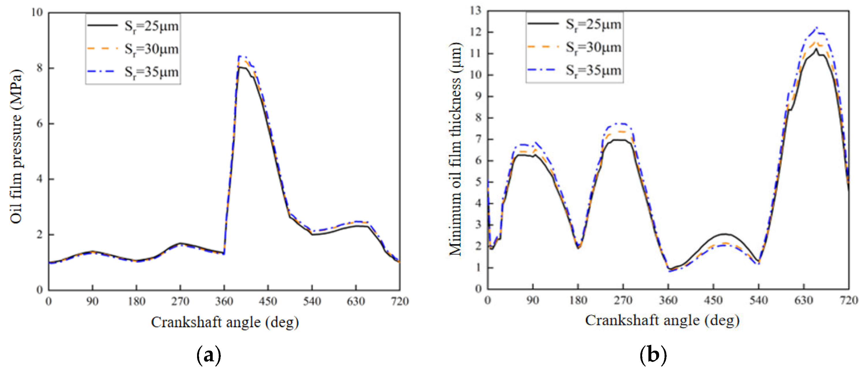
3.3.3. Impact of Pit Radius on Lubrication Characteristics
3.3.4. Impact of Different Texture Shapes on Lubricating Characteristics
4. Conclusions
- (1)
- Transient thermal fluid calculations can resolve the large error of the lubrication oil assumptions for different temperature values when calculating iso-temperature lubrication. The minimum oil film thickness and friction power loss for isothermal and transient thermal fluid is approximate when the lubricant temperature is calculated using the transient thermal fluid for the average value of the oil film temperature. The transient thermal fluid-calculated friction power consumption is slightly lower.
- (2)
- In transient thermal fluids, lubrication characteristics are subject to a diverse range of structural parameters, and the radius, surface density, and depth of micro-concave pits have a more significant effect on lubrication. Using the current calculation model, the pit surface density is 20% and the depth is 5 μm from the perspective of reducing friction and improving lubrication performance; a radius of 35 μm for the ball pit combination ensures low friction force and friction power consumption as far as possible in advance to ensure that sufficient oil film thickness can be achieved to minimize the negative impact on the stability of the friction pair lubrication.
- (3)
- In well-lubricated areas, the oil film temperature for the cylindrical pit is lower than the temperature for the spherical pit; in areas where lubrication is insufficient, the oil film temperature for the spherical pit is lower than the cylindrical pit. From the perspective of reducing friction and improving lubrication characteristics, spherical pits should be selected for surface texturing, which ensures that the friction decreases while lubricating indicators such as the oil film temperature perform well.
Author Contributions
Funding
Data Availability Statement
Conflicts of Interest
Nomenclature
| Oil film thickness | |
| Average oil film pressure | |
| Average clearance | |
| Pressure flow coefficient | |
| Shear force coefficient | |
| Density of lubricant | |
| Sliding velocity of piston rings relative to the cylinder liner | |
| Overall roughness of the two contacting surfaces | |
| Comprehensive standard deviation of the roughness height of the cylinder liner | |
| Comprehensive standard deviation of the roughness height of the piston rings | |
| Contact factor | |
| Film thickness ratio | |
| Oil film pressure at the contact surface | |
| Gas pressure at the inlet of the piston rings | |
| Pressure at the oil film inlet and outlet at time t | |
| Pressure on the apparent contact surface | |
| Density of asperities | |
| Radius of curvature of rough peaks | |
| Equivalent modulus of elasticity | |
| Shear stress constant | |
| Boundary friction coefficient | |
| Friction force caused by asperity contacts | |
| Pressure caused by asperity contacts | |
| Friction coefficient of asperities | |
| Density of piston rings | |
| Specific heat capacity of piston rings | |
| Thermal conductivity of piston rings |
References
- Atulkar, A.; Pandey, R.K.; Subbarao, P.M.V. Role of textured piston rings/liners in improving the performance behaviors of IC engines: A review with vital findings. Surf. Topogr. Metrol. Prop. 2021, 9, 023002. [Google Scholar] [CrossRef]
- Delprete, C.; Razavykia, A. Piston ring-liner lubrication and tribological performance evaluation, A review. Proc. Inst. Mech. Eng. Part J J. Eng. Tribol. 2018, 232, 193–209. [Google Scholar] [CrossRef]
- Forero, J.D.; Ochoa, G.V.; Alvarado, W.P. Study of the piston Secondary movement on the tribological performance of a single Cylinder low-displacement diesel engine. Lubricants 2020, 8, 97. [Google Scholar] [CrossRef]
- Zimmer, M.; Vlădescu, S.C.; Mattsson, L.; Fowell, M.; Reddyhoff, T. Shear-area variation, A mechanism that reduces hydrodynamic friction in macro-textured piston ring liner contacts. Tribol. Int. 2021, 161, 107067. [Google Scholar] [CrossRef]
- Xiu, Y.L.; Jiao, B.; Lu, X.; Zou, D.; Ma, X.; Neville, A. A statistical piston ring lubrication model considering the tribofilm and its effect of two-stroke Marine engines. Tribol. Int. 2023, 177, 107996. [Google Scholar] [CrossRef]
- Zavos, A.; Nikolakopoulos, P.G. Modelling of transient flow of piston ring-liner contact using synthetic lubricants. Proc. Inst. Mech. Eng. Part J J. Eng. Tribol. 2022, 236, 2042–2056. [Google Scholar] [CrossRef]
- Zavos, A. Effect of Coating and Low Viscosity oils on Piston Ring Friction under Mixed Regime of Lubrication through Analytical Modelling. Lubricants 2021, 9, 124. [Google Scholar] [CrossRef]
- Jiao, B.; Li, T.; Ma, X.; Wang, C.; Xu, H.; Lu, X.; Liu, Z. Lubrication analysis of the piston ring of a two-stroke marine diesel engine considering thermal effects. Eng. Fail. Anal. 2021, 129, 105659. [Google Scholar] [CrossRef]
- Zhou, L.; Bai, M.L.; Sun, G.H. 3D heat transfer, lubrication and friction coupled study for piston ring-liner on diesel engines. J. Mech. Sci. Technol. 2019, 33, 939–953. [Google Scholar] [CrossRef]
- Mishra, P.C. Thermal Modeling of Thin Lubricant Film Within Piston Compression Ring and Rough Cyliner Conjuction. Front. Mech. Eng. 2020, 5, 68. [Google Scholar] [CrossRef]
- Zhou, L.; Sun, G.H.; Guo, Y.Y.; Bai, M.L. Effects of ring pack friction heat on temperature fields of piston set-liner. Int. J. Automot. Technol. 2020, 21, 1569–1578. [Google Scholar] [CrossRef]
- Takata, R.K. Effects of Lubricant Viscosity and Surface Texturing on Ring-Pack Performance in Internal Combustion Engines; Massachusetts Institute of Technology: Cambridge, MA, USA, 2006. [Google Scholar]
- Guo, S.G.; Wang, B.; Chang, Q.Y. Transient Thermal Hydrodynamic Lubrication Analysis of Textured Piston Ring/Cylinder Liner. Solid State Phenom. 2018, 279, 172–178. [Google Scholar] [CrossRef]
- Gu, C.X.; Meng, X.H.; Zhang, D. Analysis of the coated and textured ring/liner conjunction based on a thermal mixed lubrication model. Frication 2018, 6, 420–431. [Google Scholar] [CrossRef]
- Liu, Z.; Ning, X.; Meng, X.; Liao, Q.; Wang, J. Starved lubrication analysis for the top ring and cylinder liner of a Two-stroke marine diesel engine considering the thermal effect of friction. Int. J. Engine Res. 2023, 24, 336–359. [Google Scholar] [CrossRef]
- Patio, N.; Cheng, H. Application of average flow model to lubrication between rough sliding surfaces. J. Lubr. Technol. 1979, 101, 220–229. [Google Scholar]
- Greenwood, J.A.; Tripp, J. The contact of two nominally flat rough surfaces. Proc. Inst. Mech. Eng. 1970, 185, 625–633. [Google Scholar] [CrossRef]
- Masjedi, M.; Khonsari, M. Theoretical and experimental investigation of traction coefficient in line-contact EHL of rough surfaces. Tribol. Int. 2014, 70, 179–189. [Google Scholar] [CrossRef]
- Morris, N.; Leighton, M.; De la Cruz, M.; Rahmani, R.; Rahnejat, H.; Howell-Smith, S. Combined numerical and experimental investigation of the micro-hydrodynamics of chevron-based textured patterns influencing junctional friction of sliding contacts. Proc. Inst. Mech. Eng. Part J J. Eng. Tribol. 2015, 229, 316–335. [Google Scholar] [CrossRef]
- Morris, N.; Rahmani, R.; Rahnejat, H.; King, P.D.; Howell-Smith, S. A numerical model to study the role of surface textures at top dead center Reverse in the pistol ring to cylinder liner contact. J. Tribol. 2016, 138, 021703. [Google Scholar] [CrossRef]


| Parameter Name | Value |
|---|---|
| Cylindrical pit depth hp/μm | 5–10 |
| Cylindrical/Spherical pit radius rp/μm | 25–40 |
| Texture density sp | 20–40% |
| Liner surface finish /μm | 0.4 |
| Piston ring surface finish /μm | 0.4 |
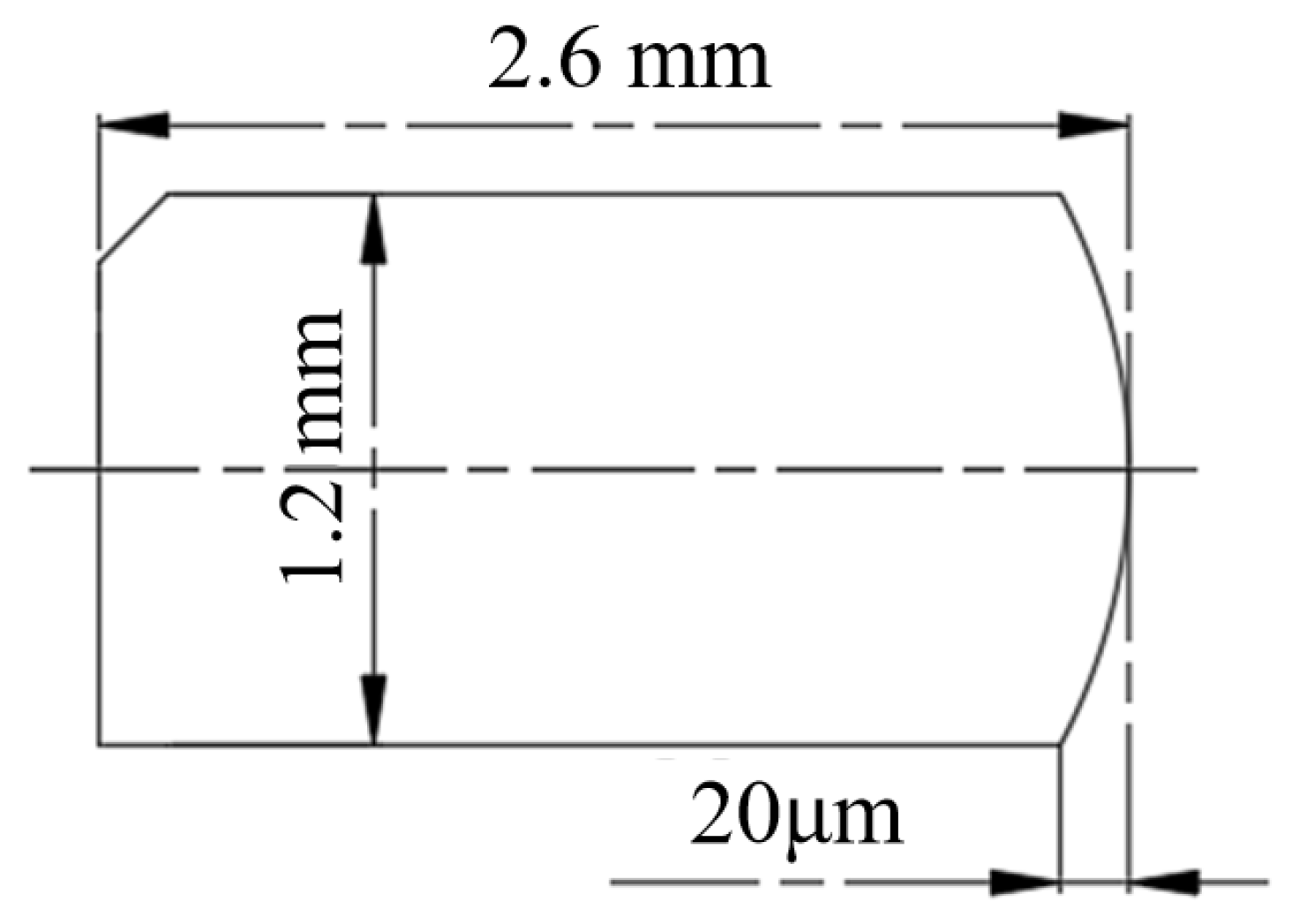
| Piston ring barrel height δ/μm | 20 |
| Piston ring axial width b/μm | 1.5 |
| Parameter Name | Value |
|---|---|
| Cylinder diameter D/mm | 126 |
| Crank radius R/mm | 65 |
| Connecting rod length l/mm | 200 |
| Speed n/(r·min−1) | 2000 |
| Lubricant number | 15W-40 |
| Lubricant density ρ/(kg·m−3) | 887 |
| Viscosity at a reference temperature /Pa·s | 1.2 × 10⁻⁴ |
| The lubricant is the heat-to-heat capacity cp/(J·(kg·s)−1) | 1880 |
| Lubricating oil heat transfer coefficient | 0.12 |
| Viscosity coefficient α2 | 0.042 |
| Adhesive pressure coefficient α1 | 2.2 e−8 |
| Validation Scheme Label | Pit Diameter/μm | Depth/μm | Axial Spacing/μm | Radial Spacing/μm |
|---|---|---|---|---|
| 1 | 50 | 5 | 600 | 400 |
| 2 | 60 | 8 | 500 | 510 |
| 3 | 70 | 10 | 300 | 500 |
| Scheme Number | Test Value | Calculated Value | Difference |
|---|---|---|---|
| 1 | 0.07742 | 0.07553 | 2.44% |
| 2 | 0.07114 | 0.079071 | 11.15% |
| 3 | 0.07015 | 0.076925 | 9.65% |
Disclaimer/Publisher’s Note: The statements, opinions and data contained in all publications are solely those of the individual author(s) and contributor(s) and not of MDPI and/or the editor(s). MDPI and/or the editor(s) disclaim responsibility for any injury to people or property resulting from any ideas, methods, instructions or products referred to in the content. |
© 2023 by the authors. Licensee MDPI, Basel, Switzerland. This article is an open access article distributed under the terms and conditions of the Creative Commons Attribution (CC BY) license (https://creativecommons.org/licenses/by/4.0/).
Share and Cite
Zhang, H.; Liu, X.; Gong, J.; Bai, S.; Sun, K.; Jia, H. Thermohydrodynamic Lubrication Characteristics of Piston Rings in Diesel Engine Considering Transient Heat Transfer under the Parameterized Surface Texture of Cylinder Liners. Energies 2023, 16, 7924. https://doi.org/10.3390/en16247924
Zhang H, Liu X, Gong J, Bai S, Sun K, Jia H. Thermohydrodynamic Lubrication Characteristics of Piston Rings in Diesel Engine Considering Transient Heat Transfer under the Parameterized Surface Texture of Cylinder Liners. Energies. 2023; 16(24):7924. https://doi.org/10.3390/en16247924
Chicago/Turabian StyleZhang, Hongyang, Xiaori Liu, Junzhen Gong, Shuzhan Bai, Ke Sun, and Haoran Jia. 2023. "Thermohydrodynamic Lubrication Characteristics of Piston Rings in Diesel Engine Considering Transient Heat Transfer under the Parameterized Surface Texture of Cylinder Liners" Energies 16, no. 24: 7924. https://doi.org/10.3390/en16247924