Article

An Ejector and Flashbox-Integrated Approach to Flue Gas Waste Heat Recovery: A Novel Systematic Study

School of Energy and Power Engineering, Shandong University, Jinan 250061, China
*
Author to whom correspondence should be addressed.
Energies 2023, 16(22), 7607; https://doi.org/10.3390/en16227607
Submission received: 18 September 2023 / Revised: 29 October 2023 / Accepted: 14 November 2023 / Published: 16 November 2023
(This article belongs to the Topic Waste-to-Energy)

Abstract

:
In this study, a comprehensive examination was conducted to explore the technology involved in the recovery of waste heat from flue gas emitted by a 1000 MW unit. Traditional methods are constrained in their ability to harness waste heat from flue gas solely for the purpose of generating medium-temperature water. The system being examined not only recovers waste heat but also utilizes it to generate steam, thereby greatly improving resource efficiency. The process entails utilizing the flue gas to heat water to a certain temperature, followed by subjecting it to flash evaporation. This process leads to the generation of low-pressure waste heat steam. Within the steam ejector, the waste heat steam combines with high-pressure motive steam extracted from the source, resulting in the formation of medium-pressure steam. Within the steam ejector, the waste heat steam blends with high-pressure motive steam drawn from the source, forming medium-pressure steam that eventually feeds into the A8 steam extraction pipe (low-pressure turbine pumping pipe). The present study examines the fluctuation patterns in motive steam flow, suction coefficient, waste heat steam volume, and outlet temperature of the flue water heat exchanger when different motive steam sources are used. Additionally, the research calculates the reduction in CO2 emissions, the coal consumption for power supply, and the cost savings in fuel for the retrofitted system. The findings indicate that maximizing energy utilization can be achieved by operating the retrofitted unit at the lowest feasible waste heat steam pressure. The implementation of the new system has resulted in a substantial decrease in coal consumption for power supply. When employing main steam as the extraction steam source, the consumption of coal for power generation decreases in proportion to the decrease in waste heat steam pressure while maintaining a constant unit load. When the waste heat steam pressure reaches 0.0312 MPa, the recorded coal consumption for power generation varies between 289.43 g/kWh at 100% turbine heat acceptance (THA) and 326.94 g/kWh at 30%THA. When comparing this performance with the initial thermal power plant (TPP) unit, it demonstrates reductions of 2.26 g/kWh and 1.52 g/kWh, respectively. After implementing modifications to this 1000 MW unit, it is projected that the annual CO2 emissions can be effectively reduced by 6333.97 tons, resulting in significant cost savings of approximately USD 0.23 million in fuel expenses. This system exhibits considerable potential in terms of emission reduction and provides valuable insights for thermal power plants aiming to decrease unit energy consumption.

1. Introduction

1.1. Research Background

The heightened global focus on waste heat recovery can be attributed to the escalating greenhouse effect resulting from the utilization of fossil fuels, the diminishing availability of these resources, and the continuously expanding need for energy security. In recent years, there has been a growing recognition of waste heat as a valuable and cost-free source of energy in industrial power plants. As a result, various strategies have been developed and implemented to effectively harness this energy [1]. A notable opportunity for improving the overall energy efficiency of current thermal power plant (TPP) systems lies in the utilization of waste heat recovery. This approach not only reduces the consumption of primary energy sources but also significantly mitigates pollutant emissions [2]. To tackle these challenges, the most effective approach is to harness waste heat from flue gas, thereby substantially mitigating pollutant emissions in TPP systems. However, the development of efficient strategies for harnessing the waste heat derived from flue gas continues to be a significant challenge in contemporary thermal power plant (TPP) systems.

1.2. Literature Review

1.2.1. Waste Heat Recovery

A considerable quantity of waste heat is continuously being dissipated within industrial environments, leading to the wastage of energy and the aggravation of environmental pollution [3]. The exploration of waste heat utilization in thermal power plants has been a topic of extensive scholarly inquiry for numerous years. Typically, a range of heat pumps is employed as the predominant technology to recover the waste heat produced in power plants. R.W. Timmerman [4] emphasized the potential of utilizing power plant waste heat for heating purposes. Concurrently, J.J. Bonilla [5] highlighted the significant potential of heat pumps in facilitating waste heat recovery. Notably, a municipal composting plant successfully raised the waste heat temperature to 82 °C using a single-stage absorption heat pump, and this was able to meet the heating requirements of a commercial area in southern Germany [6]. Additionally, studies by Song Hwa Chae et al. [7] and S. Smolen et al. [8] have emphasized the economic and environmental advantages conferred by the efficient management of industrial waste heat. Various novel strategies have been suggested to tackle the pressing challenges associated with the high temperatures and suboptimal utilization rates of waste heat in industries characterized by significant radiant heat. For instance, Wang, H.T. et al. [9] introduced an endothermic screen model, aiming to reduce the objective of high temperature and low utilization of waste heat in industrial plants with high radiant heat. Zhang, J.H. et al. [10] proposed the utilization of a generalized predictive controller to regulate the waste heat recovery process based on an organic Rankine cycle. The study by Ni, T.M. et al. [11] introduced a groundbreaking waste heat recovery system integrating a transcritical CO2 setup, an organic Rankine cycle (ORC), and a compression heat pump/refrigeration system. This groundbreaking system enabled the transition from a heat pump to a refrigeration unit without requiring equipment replacement, promising substantial cost savings. The preliminary findings indicated promising maximum energy and exergy efficiencies of 71.75% and 67.92%, respectively, when coupled with the waste-to-energy (WTE) process. Based on the heating load characteristics, Wang, J.S. et al. [12]. put forward a design concept that employs an absorption heat pump to capture the waste heat emitted from a steam turbine exhaust for heating applications. Concurrently, Sun, Y.Q. et al. [13] outlined a revolutionary approach to recover waste heat from high-temperature slags utilizing time temperature transformation (TTT) curves as a fundamental tool. Furthermore, the study conducted by Tanczuk, M. et al. [14] examined the different technical ways available for extracting the precise enthalpy of slag from a 45 MW thermal capacity grate-fired district heating boiler. Embarking on a novel pathway, Zhang, L. et al. [15] utilized exergy analysis, a methodology capable of quantifying the amount of recovered energy from heat, for evaluating a flue gas condensation waste heat recovery system. Additionally, Nyamsi, S.N. et al. [16] demonstrated the significant potential harbored by the incorporation of thermal energy storage systems (TES) in waste heat recovery applications, greatly enhancing energy efficiency. This study presented a two-dimensional mathematical model to analyze the efficiency of a two-tank thermochemical heat storage system utilizing Mg2Ni/LaNi5 metal hydrides for high-temperature waste heat recovery. Durcansky, P. [17] dealt with application options and individual parameters that impacted the efficiency of the Stirling engine for waste heat recovery. The analysis revealed that this kind of engine was capable of recovering and harnessing heat exceeding 300 °C, which exhibited its potential for use with solar energy. In the study of He [18], two systems were evaluated for recovery of the waste heat from a proton-exchange membrane fuel cell (PEMFC), which were named the organic Rankine cycle (ORC) and the heat pump (HP) combined organic Rankine cycle (HPORC). The results indicated that the HPORC system was significantly more viable for the cooling system of a PEMFC stack since the enhanced heat recovery ability could be promoted due to the presence of the HP.

1.2.2. Waste Heat Recovery Utilizing Ejectors

The application of ejectors in the realm of waste heat recovery has garnered significant attention in numerous research endeavors, underscoring the potential of this as a viable strategy for enhancing energy efficiency and advancing conservation initiatives. Kumar, R. et al. [19] carried out a comprehensive thermodynamic analysis incorporating both energy and exergy methods to evaluate the efficiency of an ejector compression refrigeration system that integrated an internal heat exchanger and cooler to enhance the cycle’s performance. Furthermore, Sun et al. [20] presented a pioneering district heating system with combined heat and power (CHP) based on ejector heat exchangers and absorption heat pumps (DH-EHE). This system aimed to reduce the energy consumption of existing CHP frameworks by recovering the waste heat discharged from steam turbines. Additionally, the research by Bashiri, H. et al. [21] indicated that the integration of optimal heat recovery strategies with ejector technology could yield significant utility savings. Their findings highlighted the potential decrease in steam and cooling water consumption of up to 23% and 16%, respectively. On the other hand, Khaliq, A. et al. [22] integrated a LiBr-H2O absorption refrigeration system into a combined power and ejector refrigeration setup utilizing R141b as the working fluid. Concurrently, Mondal et al. [23] scrutinized the performance of an organic flash cycle (OFC) driven by low-grade waste heat and facilitated through an ejector. Complementing this, Riaz, F. et al. [24] introduced a thermal modeling and optimization framework for a low-grade waste-heat-driven ejector refrigeration system, incorporating a direct ejector model into their study. Al-Sayyab, A.K.S., et al. [25] embarked on an investigation of the theoretical performance of a novel compound system that combined waste heat and solar energy, employing an ejector solar-assisted heat pump. This innovation held promise for concurrent heating and cooling applications, thereby potentially facilitating more environmentally sustainable energy solutions in the future.

1.3. Novelty and Contribution

In light of the prevailing difficulties encountered by coal-fired power units, this study undertakes a comprehensive analysis of the thermodynamic properties of ejectors and the recovery of waste heat from flue gas. A comprehensive analysis has been conducted on the topic of waste heat recovery and quality enhancement for a 1000 MW unit. A novel waste heat recovery system utilizing steam ejectors is proposed as a means to mitigate energy consumption and reduce CO2 emissions in the unit. Traditional techniques solely focus on the recovery of waste heat from flue gas for the purpose of generating medium-temperature water. This system, however, not only facilitates the recovery of waste heat but also utilizes it to generate steam, thereby improving resource efficiency. This system demonstrates significant potential in terms of reducing emissions and offers valuable insights for thermal power plants seeking to decrease their unit energy consumption.

2. Thermodynamic Model Development

2.1. Case Thermal Power Plant System

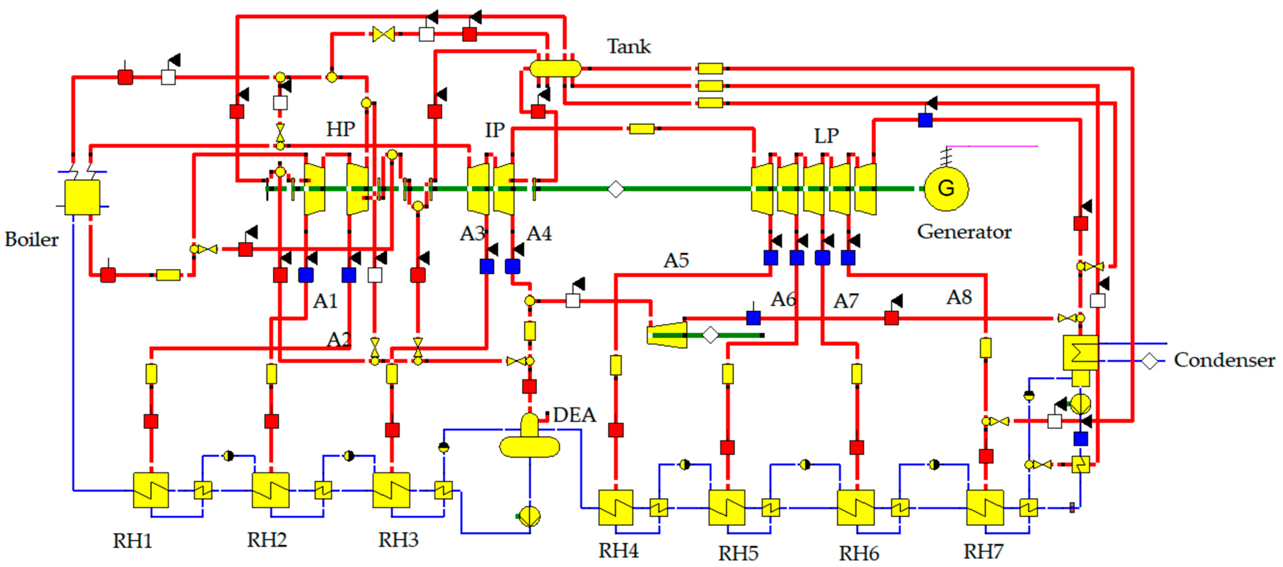
2.1.1. Modeling of the Conventional TPP System

A thermal system was designed and simulated using Ebsilon software (Ebsilon 15) to analyze the performance of a 1000 MW coal-fired unit under various operating conditions, including VWO, THA, 50%THA, and 40%THA. The system configuration is illustrated in Figure 1. The key components comprising this thermal system encompass the boiler, steam turbine, condenser, condensate pump, deaerator, regenerative heater, feedwater pump, and an assortment of pipes, among other elements.

2.1.2. Model Accuracy Verification

The parameters of the 1000 MW coal-fired unit under VWO, THA, 50%THA, and 40%THA conditions, established through Ebsilon, are verified against the original thermal balance diagram. The findings are presented in Table 1.
From the analysis presented in Table 1, it is evident that the fluctuations in the primary parameters on the turbine side are limited to a range of 4%. This observation implies that the disparity in the model’s efficacy remains within acceptable thresholds, thus confirming the accuracy of the simulation results within the specified design parameters.

2.2. Waste Heat Recovery System

In this section, a thorough examination of the waste heat recovery and upgrade strategies for the 1000 MW unit has been undertaken. A novel methodology has been proposed to enhance the recovery of waste heat by employing the steam ejector. The aim of this study is to ascertain the most suitable source of motive flow and examine the fluctuations in motive flow, suction coefficient, waste heat quantity, and heat exchanger outlet flue temperature under various conditions and waste heat steam pressures. The main objective is to reduce coal consumption for power supply and diminish carbon dioxide (CO2) emissions.

2.2.1. Analysis of Extraction Steam Sources

In order to accomplish the goals of waste heat recovery and the mitigation of CO2 emissions, this section investigates the feasibility of utilizing various extraction steam locations as the power steam source for the steam ejector. Upon careful assessment of the present state of the 1000 MW unit, a number of potential steam sources have been identified. The steam sources in this system include main steam, reheat steam, and extraction steam from A1 to A8, resulting in a total of 10 extraction steam sources. The subsequent section presents a comprehensive analysis of all potential sources of steam.
(1)
Main Steam: The main steam exhibits superior pressure parameters, thereby providing it with a comparative advantage over other steam sources.
(2)
Reheat Steam, A1 Steam, A2 Extraction Steam: Despite possessing lower pressure parameters and necessitating a greater volume of extraction to discharge an equivalent amount of steam compared with the main steam, these three categories of steam can still function as motive flow sources for the waste heat upgrading system.
The extraction steam from A4 to A8 is considered unsuitable for the current waste heat upgrading system due to its low-pressure parameters.
The primary objective of the present study is to investigate the main steam, reheat steam, A1 extraction steam, and A2 extraction steam as the main areas of research.

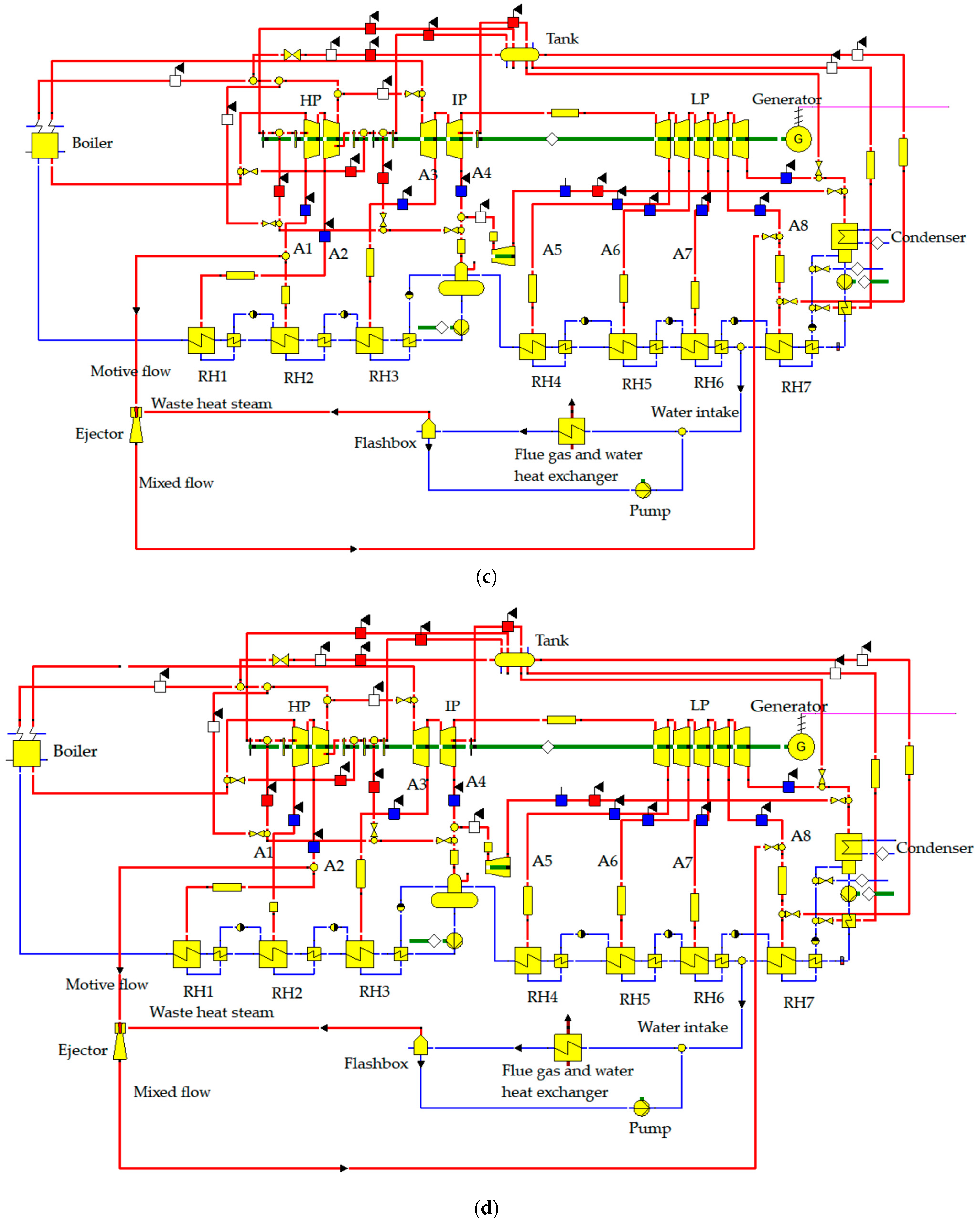
2.2.2. Description of the New Waste Heat Recovery System

The operational procedure of the waste heat recovery system can be delineated as follows:
On the flue gas side, the water in the regenerative heater is heated by utilizing the flue gas, which is expelled from the air preheater as a source of heat. The achievement of this objective is facilitated by employing a heat exchanger.
On the steam side, a predetermined quantity of water is extracted from the regenerative heater and subsequently subjected to heating in the flue gas–water heat exchanger. After being heated to a temperature of 100 °C, the substance is subsequently introduced into the flash evaporation tank in order to undergo the process of flash evaporation. The low-pressure waste heat steam produced during the flashing process is combined with the high-pressure motive flow extracted from the steam source within the ejector. The aforementioned combination results in the transformation of the high-pressure flow into medium-pressure steam, which subsequently merges with the A8 steam extraction pipe.
According to the analysis conducted on the power steam source in Section 2.2.1, four potential options for the waste heat recovery system were identified for further investigation. The visual depictions illustrating the aforementioned concepts can be observed in Figure 2a–d.

2.2.3. Initial Conditions

The flue gas flow rate at the outlet of the air pre-preheater, flue gas temperature, parameters of each condition, and parameters of each extraction source under 100%THA to 30%THA conditions are shown in Table 2 and Table 3.

2.3. Mathematical Model

2.3.1. Ejector

In this paper, the ejector calculation model utilizes Gea’s calculation method for the ejector. The structure of the steam ejector is illustrated in Figure 3.
Calculation of motive flow at design conditions:
E = P 3 P 1
K = P 2 P 1
M 3 = b ( E , K ) 0.73537 M 1 f 2
where b and  f 2  are the correction factors.
Calculation of motive flow at off-design conditions:
M 3 = P 2 ln ( P 3 P 1 ) b ( E , K ) 0.73537 M 1 P 1 f 2
The extension of the equation from characteristic curves to non-design conditions is achieved through the incorporation of two correction factors.

2.3.2. Flue Gas and Water Heat Exchanger

According to the law of conservation of energy, the energy equation for the flue gas and water heat exchanger in the waste heat recovery system can be expressed by Equations (5) and (6).
k A L M T D = M 2 H 2 M 1 H 1
k A L M T D = M 3 H 3 M 4 H 4 Q L O S S
The mean logarithmic temperature difference (LMTD) is a parameter used to quantify the temperature difference in heat transfer processes. QLOSS represents the amount of heat lost to the surrounding environment. The numbers 1 and 2 are used to denote the inlet and outlet of the waterside, whereas the numbers 3 and 4 are used to represent the inlet and outlet of the flue gas side, respectively.

2.3.3. Flashbox

The dryness, condensate temperature, and enthalpy of the flashbox are determined using Equations (7)–(9).
x = f ( P 2 , H 1 )
T 3 = T 3 S D T 3 S 3
H 3 = f ( P 3 , T 3 S D T 3 S 3 )
In the given context, the variable x represents the degree of dryness, DT3S3 represents the temperature difference during the recooling process, and f denotes the water vapor function relationship. Additionally, T3S represents the saturation temperature at point 3.

2.3.4. Evaluation Indicators

(1)
Motive Flow M3. The economic benefits are significant when the motive flow rate is reduced, as it necessitates less steam from the steam extraction source.
(2)
The Suction Coefficient λ. The relationship between the suction coefficient and the motive steam flow is such that as the suction coefficient increases, the amount of motive steam required to produce the same amount of steam from the steam ejector decreases. Consequently, this leads to an improved economy.
λ = Waste   heat   steam   flow Motive   flow
(3)
Flash Steam Flow  M f . Under identical circumstances, an increased volume of flash steam flow signifies a greater amount of recovered waste heat and enhanced economic advantages.

2.3.5. Power Supply Coal Consumption

The term “power supply coal consumption” refers to the amount of standard coal consumed for every unit of electricity delivered to the external grid by a power generation facility, after subtracting the plant’s own electrical consumption. The computational formula is explicated in the following section.
For TPP (thermal power plant) units, the calculation of power supply coal consumption (B) is as follows:
B = b 1 α
b = q η 1 × η 2 × L H V × 1000
q 1 = Q z q Q g s + Q z r Q l z P e × 3600
q 2 = Q z q Q g s + Q z r Q l z ( Q g r Q n s ) P e × 3600
B c c = B × Q G D i 1,000,000
Δ B = Δ b P e t
In the equation,  α  denotes the power plant electricity consumption rate and the term “LHV” symbolizes the lower heating value (heat consumption) of coal, kJ/kg, utilizing a benchmark delineated by the characteristics of standard coal. q is the turbine heat consumption rate; kJ/kWh, q1 is the heat consumption rate of the power plant in the non-heating season; q2 is the heat consumption rate of the power plant in the non-heating season, kJ/kWh; Qzq is the main steam heat, kW; Qgs is the heat of the feed water, kW; Qzr is the heat of reheated steam, kW; Qlz is the heat of reheat cold section, kW; Qgr is the amount of heat supplied, kW; Qns is the heat of condensate evacuation, kW; b is the coal consumption rate for power generation, g/kWh; B is the rate of coal consumption for power supply, g/kWh; Bcc is the amount of coal consumption for power supply, t; Pe is the power generated by the turbine, kW; QGDi is the power supply under different operating conditions, kW, where i = 1~8 denotes THA, 90% THA, 80% THA, 70% THA, 60% THA, 50% THA, 40% THA, 30% THA working conditions, respectively.

3. Results and Discussion

In this section, simulation calculations are conducted using the EBSILON system modeling approach to investigate various parameters, including motive flow, suction coefficient, flash steam flow, and flue gas temperature at the outlet of the flue gas–water heat exchanger. These calculations are performed under different operating conditions, ranging from 100% to 30% loads, with the aim of determining the optimal solution.
The change in performance under different loads exhibits similarities, with only slight variations in the pressure parameter of each motive steam source, the water intake temperature, and the flue gas temperature at the outlet of the air preheater. However, these variations do not alter the overall characteristics of the waste heat recovery system, thus indicating a similar change pattern. Consequently, this section exclusively focuses on presenting and elucidating the simulation outcomes obtained under a 100% THA load.

3.1. Effects of Waste Heat Steam Pressure on Four Extraction Sources at 100% THA

The waste heat recovery system was simulated in the EBSILON computing environment to analyze its performance under 100% THA operating conditions. The simulation results revealed the variations in the motive flow, suction coefficient, flash steam flow, and flue–water heat exchanger outlet flue temperature at different waste heat steam pressures, as depicted in the Figures. The range of numbers is from 4 to 7.

3.1.1. The Relationship between Motive Flow and Waste Heat Steam Pressure

Figure 4 illustrates the relationship between motive flow and waste heat steam pressure when different extraction sources, such as main steam, A1 steam, A2 steam, and reheat steam, are utilized.
As depicted in Figure 4, under 100%THA operating conditions and with specified water extraction parameters and flue gas parameters:
(1)
The motive flow required by the four extraction sources gradually decreases with the increase in waste heat steam pressure. This phenomenon can be attributed to the inverse relationship between induced steam pressure and the compression ratio of medium-pressure steam to induced steam. As the induced steam pressure increases, the compression ratio decreases, resulting in a lower demand for motive steam.
(2)
The power steam flow required by the four extraction sources, when the pressure of the waste heat steam is kept constant, follows the following order: main steam < A2 steam < A1 steam < reheat steam. The relationship between motive steam pressure and the amount of steam required to raise the waste heat steam to medium-pressure steam is inversely proportional. As the motive steam pressure increases, the amount of steam needed decreases.

3.1.2. The Relationship between Flash Steam Flow and Waste Heat Steam Pressure

Figure 5 illustrates the relationship between flash steam flow and waste heat steam pressure, considering different extraction sources such as main steam, A1 steam, A2 steam, and reheat steam.
As depicted in Figure 6, under 100% THA operating conditions the water intake parameters and flue gas parameters were considered.
(1)
A decrease in the amount of flashed steam is observed as the waste heat steam pressure increases.
(2)
The quantity of flash steam remains constant across various extraction sources when subjected to identical waste pressures. The similarity in the four types of extraction sources lies in their dependence on both feed water parameters and flue gas parameters. Specifically, when the waste heat steam pressure remains constant, the flash steam temperature and pressure also remain constant. Consequently, the change in flash steam flow follows a consistent pattern.

3.1.3. The Relationship between Suction Coefficient and Waste Heat Steam Pressure

Figure 6 illustrates the relationship between the suction coefficient and waste heat steam pressure when different extraction sources, including main steam, A1 steam, A2 steam, and reheat steam, are utilized.
As depicted in Figure 5, when the THA condition is set at 100%, the water extraction parameters and flue gas parameters remain constant.
(1)
The suction coefficient exhibits a consistent pattern of initially decreasing and then increasing as the waste heat steam pressure increases, indicating an overall upward trend.
The mathematical fitting equations for Figure 4 motive flow and Figure 5 flash steam flow (fitting coefficient R2 > 0.99) can be expressed as follows, respectively.
y m = { 15,670 x 2 + 324.47 x + 268.61 0.031   <   x   <   0.051 80,076 x 2 15,835 x + 835.52   x   >   0.051 }
y f = 3237.1 x 2 816.92 x + 59.88
According to Equations (10), (17), and (18), derivation of the function of the suction coefficient λ shows that when 0.031 < flash steam pressure < 0.051, λ’ < 0 and the suction coefficient λ function decreases gradually; when flash steam pressure > 0.051, λ’ > 0 and the suction coefficient λ function becomes progressively higher. Therefore, the lowest suction coefficient occurs for flash steam pressure = 0.051 MPa.
(2)
The suction coefficients of the four extraction sources, namely main steam, A2 steam, A1 steam, and reheat steam, follow the following order when the pressure of waste heat steam remains constant: main steam > A2 steam > A1 steam > reheat steam.

3.1.4. The Relationship between Heat Exchanger Outlet Flue Temperature and Waste Heat Steam Pressure

Figure 7 illustrates the relationship between the outlet flue temperature of the heat exchanger and the waste heat steam pressure, considering different extraction sources such as main steam, A1 steam, A2 steam, and reheat steam.
As depicted in Figure 7:
(1)
Under the given conditions of water intake parameters and flue gas parameters, it is observed that in the 100% THA condition, the outlet flue gas temperature of the flue gas water heat exchanger increases with an increase in the pressure of the waste heat steam. This can be attributed to the decrease in the amount of flash flow as the pressure of the waste heat steam increases. Consequently, the amount of supplemental water required for the self-circulation of the waste heat recovery system decreases, leading to a decrease in the overall water flow rate of the waste heat recovery system. As a result, the heat exchange on the flue gas side decreases, causing the flue gas outlet temperature to rise.
(2)
The outlet flue temperature of the heat exchanger remains consistent across different extraction sources when subjected to the same waste pressure. The similarity between the four types of extraction sources lies in their feed water parameters and flue gas parameters. Specifically, when the waste heat steam pressure remains constant, the flash steam temperature and pressure also remain constant. As a result, the heat exchanger outlet flue temperature follows the same pattern of change.

3.2. Effects of Waste Heat Steam Pressure on Four Extraction Sources at 90% THA

The variation in motive flow, suction coefficient, flash steam flow, and heat exchanger outlet flue temperature under different waste heat steam pressures of the waste heat recovery system in a 90%THA working condition is illustrated in Figure 8.
As depicted in Figure 8, under the 90%THA condition, the variation pattern of motive flow, suction coefficient, flash steam flow, and heat exchanger outlet flue temperature with respect to the waste heat steam pressure is comparable with that observed under the 100% THA condition.

3.3. Effects of Waste Heat Steam Pressure on Four Extractions at 80% THA

The alteration pattern of each parameter under the condition of 80%THA is depicted in Figure 9.
As depicted in Figure 9, the alteration patterns of power steam flow, suction coefficient, flash steam flow, and heat exchanger outlet flue temperature with respect to the waste heat steam pressure are comparable at both 80% and 100% THA.

3.4. Effects of Waste Heat Steam Pressure on Four Extraction Sources at 70% THA–30% THA

In 70% THA–30% THA working conditions, the change rule for each parameter is similar to that in 100% THA–80% THA working conditions.

3.5. The Optimal Strategy among the Four Extraction Sources

Based on the analysis of motive flow, suction coefficient, flash steam flow, and heat exchanger outlet flue temperature in the waste heat recovery system under 100% THA–30% THA working conditions in Section 3.1, Section 3.2, Section 3.3 and Section 3.4, it can be inferred that when main steam is utilized as the extraction source, it exhibits the lowest required motive flow, a higher suction coefficient, and greater economic efficiency compared with the other extraction sources.

3.5.1. The Variation in Motive Flow Based on the Main Steam

The figure presented in Figure 10 illustrates the necessary motive flow for each operating condition of the 100% THA–30% THA range when the main steam is utilized as the source of extraction.
From Figure 10, it is evident that:
(1)
When the unit load increases, the amount of motive flow required also increases, assuming the same waste heat steam pressure.
(2)
As the waste heat steam pressure increases, the required motive flow decreases at the same load.
(3)
Within the investigated range, as the waste heat steam pressure varies from 0.03 MPa to 0.09 MPa, the corresponding motive flow rates under different unit loads range from 120.53 t/h at the highest to 0.72 t/h at the lowest.

3.5.2. The Variation in the Suction Coefficient Based on the Main Steam

The suction coefficient for each operating condition in the 100% THA–30% THA range, with main steam as the source of extraction, is depicted in Figure 11.
From Figure 11, it can be seen that:
(1)
When the waste heat steam pressure exceeds 0.05 MPa, there is a general decrease in the suction coefficient trend as the unit load increases at the same waste heat steam pressure.
(2)
As the waste heat steam pressure increases, there is an initial decrease followed by an increase in the suction coefficient for a portion of the load.
(3)
The suction coefficient increases proportionally with the waste heat steam pressure for a given load.
(4)
Within the investigated range, the suction coefficient ranges from 0.24 to 0.77 as the waste heat steam pressure is varied from 0.03 MPa to 0.09 MPa.

3.5.3. The Variation in the Flash Steam Flow Based on the Main Steam

The diagram in Figure 12 illustrates the flash steam flow for each operating condition in the 100% THA–30% THA range when the main steam is used as the source of extraction.
From Figure 12, it can be seen that:
(1)
When the waste heat steam pressure remains constant, an increase in unit load results in a greater quantity of flash steam.
(2)
It has been observed that with an increase in waste heat steam pressure, there is a corresponding decrease in the amount of flash steam generated for the same load.
(3)
Within the investigated range, as the waste heat steam pressure varies from 0.03 MPa to 0.09 MPa, the minimum flow rate of flash steam is 0.52 t/h, whereas the maximum flow rate reaches 37.85 t/h.

3.5.4. The Variation in the Heat Exchanger Outlet Flue Temperature Based on the Main Steam

The diagram in Figure 13 illustrates the heat exchanger outlet flue temperature for each operating condition in the 100% THA–30% THA range when the main steam is used as the source of extraction.
From Figure 13, it can be seen that:
(1)
Under the same waste heat steam pressure, the flue gas temperature at the heat exchanger outlet increases as the unit load increases;
(2)
Under the same load conditions, the flue gas outlet temperature gradually increases as the waste heat steam pressure increases;
(3)
In the studied range, when the waste heat steam pressure changes from 0.03 MPa to 0.09 MPa, the heat exchanger outlet flue temperature is as low as 70.14 °C and as high as 112.91 °C.

3.6. Emission Reduction and Economic Analysis

The waste heat system can recover up to 37.85 t/h, as shown in Figure 12. The saved coal consumption is calculated as in Equation (13).
Δ B = G H W t × 1000 Q a r η b
where B stands for coal consumption, kg/h; G stands for the amount of steam, t/h; HW stands for the enthalpy of the steam, kcal/kg, which is 69.99 kcal/kg; Qar stands for the calorific value of the standard coal, 7000 kal/kg; ηb stands for the thermal efficiency of the boiler; and t stands for the total number of hours of operation of the plant in the whole year, which is 4475.08 h.
The consequential reduction in CO2 emissions can be assessed utilizing the subsequent equations [26],
Δ CO 2 = M CO 2 M C E F Δ B
Profit = Δ B Price coal
where  M CO 2  and  M C  represent the relative molecular mass of carbon dioxide and carbon, respectively, and EF denotes the emission factor, characterized by a value of 0.714. The  Price coal  in this study is given as the average of China’s carbon trading price in September 2023, which is a value of 9.53 USD/t.
Through meticulous calculation, the annual carbon dioxide emissions are discerned to be 6333.97 t, saving approximately USD 0.23 million in fuel costs.

3.7. The Comparison of Power Supply Coal Consumption between the Waste Heat Recovery System and the Original TPP System
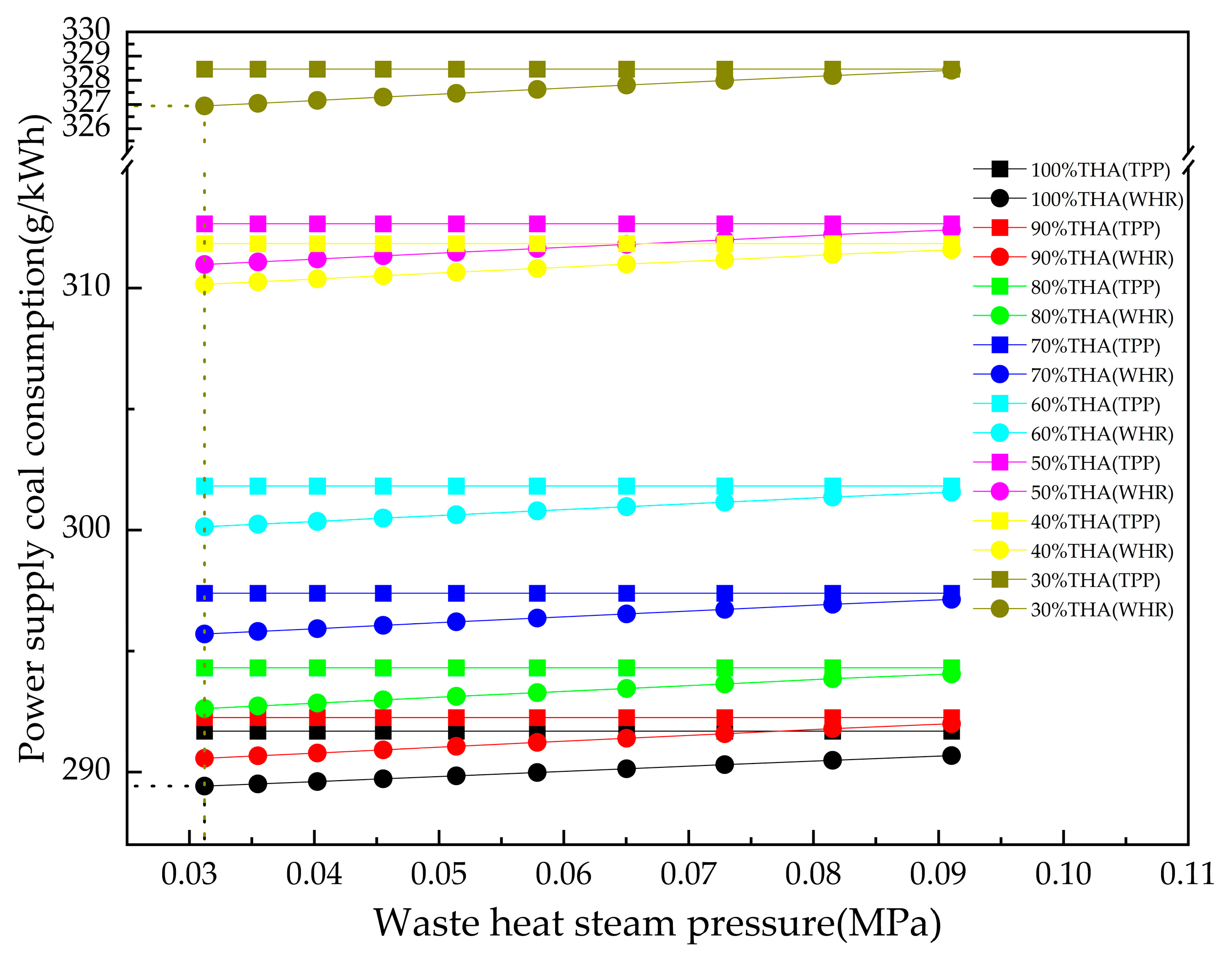
The waste heat recovery system saves energy by taking advantage of the waste heat. Therefore, the energy consumption of the original TPP unit and the waste heat recovery system unit using main steam as an extraction source was analyzed to compare the coal consumption of the power supply before and after the modification.
As shown in Figure 14, after the modification, utilizing the main steam as the extraction source resulted in decreased power supply coal consumption within the waste heat recovery system.
(1)
The coal consumption of the power supply decreases proportionally with the diminishing waste heat steam pressure under the same unit load. When the waste heat steam pressure reaches 0.0312 MPa, the power supply’s lowest coal consumption is recorded at 289.43 g/kWh (100% THA), whereas the highest is recorded at 326.94 g/kWh (30% THA). In comparison with the initial TPP unit, the waste heat recovery system demonstrates varying degrees of coal consumption reduction, achieving reductions of 2.26 g/kWh and 1.52 g/kWh, respectively.
(2)
The coal consumption of the waste heat recovery system decreases with an increase in the unit load when maintaining the same waste heat steam pressure.

4. Conclusions

In this study, a thorough examination of a 1000 MW coal-fired unit was undertaken and a novel approach for improving the quality of waste heat through the utilization of a steam ejector was suggested. This study investigated the variations in motive flow, suction coefficient, flash steam flow, and heat exchanger outlet flue temperature across different power steam sources, diverse operating conditions, and varying waste heat steam pressures. The primary findings can be summarized as follows:
(1)
The utilization of main steam was identified as the most advantageous option for the waste heat recovery system, as it requires the least amount of motive steam and exhibits a higher suction coefficient when compared with the alternative extraction sources. When the waste heat steam pressure fluctuates within the range of 0.03 MPa and 0.09 MPa, the recently developed waste heat recovery system can efficiently produce up to 37.85 t/h of waste heat steam. Additionally, this novel waste heat recovery system demonstrates a consistently high suction coefficient, with values ranging from a minimum of 0.24 to a maximum of 0.77. Additionally, the outlet flue of the heat exchanger in the new system exhibits fluctuations ranging from 70.14 °C to 112.91 °C, with an approximate mean value of 91.525 °C.
(2)
In order to minimize motive steam consumption and enhance the suction coefficient, it is recommended to lower the waste steam pressure, which necessitates increasing the flash temperature of the flashbox.
(3)
Following the modification of this 1000 MW unit, there is potential for a reduction of 6333.97 t in annual CO2 emissions, along with an estimated fuel cost savings of approximately USD 0.23 million.
(4)
The implementation of the new system results in a substantial decrease in coal consumption for power generation. When employing main steam as the extraction steam source, the consumption of coal for power supply decreases in proportion to the decrease in waste heat steam pressure when maintaining a constant unit load. When the waste heat steam pressure reaches 0.0312 MPa, the coal consumption for power generation is recorded at its lowest as 289.43 g/kWh with 100%THA and at its highest as 326.94 g/kWh with 30%THA. When comparing the performance of this unit to the initial TPP unit, it demonstrates reductions of 2.26 g/kWh and 1.52 g/kWh, respectively.

Author Contributions

Conceptualization, F.S. and Y.S.; methodology, R.W.; software, R.W.; validation, X.D. and Y.W.; formal analysis, R.W.; investigation, R.W.; resources, R.W.; data curation, R.W.; writing—original draft preparation, R.W.; writing—review and editing, R.W.; visualization, R.W.; supervision, R.W.; project administration, F.S. All authors have read and agreed to the published version of the manuscript.

Funding

This research received no external funding.

Data Availability Statement

Data are contained within the article.

Conflicts of Interest

The authors declare no conflict of interest.

Nomenclature

AArea of heat transfer, m2
EMotive steam pressure/waste heat steam pressure
GMass flow, t/h
hEnthalpy, kJ/kg
kHeat transfer coefficient,  W / ( m 2 K )  
KMedium pressure steam/waste heat steam pressure
mMass, t
PPressure, kPa
QEnergy load, kW
TTemperature, °C
xDryness
A1–A8Turbine pumping pipes
b, f2Correction factor
LMTDThe mean logarithmic temperature difference, K
QLOSSThe heat loss to the environment, kW
DT3S3Recooling temperature difference
M3Motive flow, t/h
λSuction coefficient
MfFlash steam flow, t/h
THATurbine heat acceptance
CHPCombined heat and power
TPPThermal power plant

References

  1. Deniz, C.; Durmusoglu, Y. Analysis of Environmental Effects on a Ship Power Plant Integrated with Waste Heat Recovery System. Fresenius Environ. Bull. 2016, 25, 1786–1790. [Google Scholar]
  2. Zevenhoven, R.; Beyene, A. The relative contribution of waste heat from power plants to global warming. Energy 2011, 36, 3754–3762. [Google Scholar] [CrossRef]
  3. Xu, Z.Y.; Mao, H.C.; Liu, D.S.; Wang, R.Z. Waste heat recovery of power plant with large scale serial absorption heat pumps. Energy 2018, 165, 1097–1105. [Google Scholar] [CrossRef]
  4. Timmerman, R.W. Utilization of Power Plant Waste Heat for Heating; NASA: Washington, DC, USA, 1979; pp. 2065–2083.
  5. Bonilla, J.J.; Blanco, J.M.; López, L.; Sala, J.M. Technological recovery potential of waste heat in the industry of the Basque Country. Appl. Therm. Eng. 1997, 17, 283–288. [Google Scholar] [CrossRef]
  6. Keil, C.; Plura, S.; Radspieler, M.; Schweigler, C. Application of customized absorption heat pumps for utilization of low-grade heat sources. Appl. Therm. Eng. 2008, 28, 2070–2076. [Google Scholar] [CrossRef]
  7. Chae, S.H.; Kim, S.H.; Yoon, S.-G.; Park, S. Optimization of a waste heat utilization network in an eco-industrial park. Appl. Energy 2010, 87, 1978–1988. [Google Scholar] [CrossRef]
  8. Smolen, S.; Budnik-Rodz, M. Low rate energy use for heating and in industrial energy supply systems—Some technical and economical aspects. Energy 2006, 31, 2588–2603. [Google Scholar] [CrossRef]
  9. Wang, H.T.; Zhai, J.F. Simulation Analysis of High Radiant Heat Plant Cooling and Endothermic Screen Waste Heat Recovery Performance Based on FLUENT. Energies 2023, 16, 4196. [Google Scholar] [CrossRef]
  10. Zhang, J.H.; Zhou, Y.L.; Li, Y.; Hou, G.L.; Fang, F. Generalized predictive control applied in waste heat recovery power plants. Appl. Energy 2013, 102, 320–326. [Google Scholar] [CrossRef]
  11. Ni, T.M.; Si, J.W.; Lu, F.L.; Zhu, Y.; Pan, M.Z. Performance analysis and optimization of cascade waste heat recovery system based on transcritical CO2 cycle for waste heat recovery in waste-to-energy plant. J. Clean Prod. 2022, 331, 129949. [Google Scholar] [CrossRef]
  12. Wang, J.S.; Liu, W.Q.; Liu, G.Y.; Sun, W.J.; Li, G.; Qiu, B.B. Theoretical Design and Analysis of the Waste Heat Recovery System of Turbine Exhaust Steam Using an Absorption Heat Pump for Heating Supply. Energies 2020, 13, 6256. [Google Scholar] [CrossRef]
  13. Sun, Y.Q.; Zhang, Z.T.; Liu, L.L.; Wang, X.D. Multi-Stage Control of Waste Heat Recovery from High Temperature Slags Based on Time Temperature Transformation Curves. Energies 2014, 7, 1673–1684. [Google Scholar] [CrossRef]
  14. Tanczuk, M.; Masiukiewicz, M.; Anweiler, S.; Junga, R. Technical Aspects and Energy Effects of waste Heat Recovery from District Heating Boiler Slag. Energies 2018, 11, 796. [Google Scholar] [CrossRef]
  15. Zhang, L.; Zhai, H.X.; He, J.Y.; Yang, F.; Wang, S.L. Application of Exergy Analysis in Flue Gas Condensation Waste Heat Recovery System Evaluation. Energies 2022, 15, 7525. [Google Scholar] [CrossRef]
  16. Nyamsi, S.N.; Lototskyy, M.; Tolj, I. Optimal Design of Combined Two-Tank Latent and Metal Hydrides-Based Thermochemical Heat Storage Systems for High-Temperature Waste Heat Recovery. Energies 2020, 13, 4216. [Google Scholar] [CrossRef]
  17. Durcansky, P.; Nosek, R.; Jandačka, J. Use of Stirling Engine for Waste Heat Recovery. Energies 2020, 13, 4133. [Google Scholar] [CrossRef]
  18. He, T.; Shi, R.; Peng, J.; Zhuge, W.; Zhang, Y. Waste Heat Recovery of a PEMFC System by Using Organic Rankine Cycle. Energies 2016, 9, 267. [Google Scholar] [CrossRef]
  19. Kumar, R.; Khaliq, A. Exergy analysis of industrial waste heat recovery based ejector vapour compression refrigeration system. J. Energy Inst. 2011, 84, 192–199. [Google Scholar] [CrossRef]
  20. Sun, F.T.; Fu, L.; Sun, J.; Zhang, S.G. A new waste heat district heating system with combined heat and power (CHP) based on ejector heat exchangers and absorption heat pumps. Energy 2014, 69, 516–524. [Google Scholar] [CrossRef]
  21. Bashiri, H.; Ashrafi, O.; Navarri, P. Energy-efficient process designs of integrated biomass-derived syngas purification processes via waste heat recovery and integration of ejector technology. Int. J. Greenh. Gas Control 2021, 106, 103259. [Google Scholar] [CrossRef]
  22. Khaliq, A.; Agrawal, B.K.; Kumar, R. First and second law investigation of waste heat based combined power and ejector-absorption refrigeration cycle. Int. J. Refrig.—Rev. Int. Du Froid 2012, 35, 88–97. [Google Scholar] [CrossRef]
  23. Mondal, S.; Alam, S.; De, S. Performance assessment of a low grade waste heat driven organic flash cycle (OFC) with ejector. Energy 2018, 163, 849–862. [Google Scholar] [CrossRef]
  24. Riaz, F.; Lee, P.S.; Chou, S.K. Thermal modelling and optimization of low-grade waste heat driven ejector refrigeration system incorporating a direct ejector model. Appl. Therm. Eng. 2020, 167, 114710. [Google Scholar] [CrossRef]
  25. Al-Sayyab, A.K.S.; Mota-Babiloni, A.; Navarro-Esbri, J. Novel compound waste heat-solar driven ejector-compression heat pump for simultaneous cooling and heating using environmentally friendly refrigerants. Energy Convers. Manag. 2021, 228, 113703. [Google Scholar] [CrossRef]
  26. Wang, C.; Song, J. Optimal dispatch of the cascade heating CHP plants integrating with the high back-pressure technology. Case Stud. Therm. Eng. 2022, 38, 102330. [Google Scholar] [CrossRef]
Figure 1. Thermal system simulation model of the TPP. HP—High-pressure turbine; IP—Intermediate-pressure turbine; DEA—Deaerator; LP—Low-pressure turbine; RH—Regenerative heater.
Energies 16 07607 g001
Figure 2. Waste heat recovery system. (a) Waste heat recovery system based on main steam. (b) Waste heat recovery system based on reheat steam. (c) Waste heat recovery system based on A1 steam. (d) Waste heat recovery system based on A2 steam.
Energies 16 07607 g002aEnergies 16 07607 g002b
Figure 3. Ejector structure.
Energies 16 07607 g003
Figure 4. The variation in motive flow in relation to waste heat steam pressure for four extractions.
Energies 16 07607 g004
Figure 5. The variation in flash steam flow in relation to the waste heat steam pressure.
Energies 16 07607 g005
Figure 6. The variation in the suction coefficient in relation to the waste heat steam pressure for four extractions.
Energies 16 07607 g006
Figure 7. The variation in the heat exchanger outlet flue temperature in relation to the waste heat steam pressure under 100%THA.
Energies 16 07607 g007
Figure 8. The variation in different parameters in relation to the waste heat steam pressure for four extractions under 90%THA. (a) Motive flow. (b) Suction coefficient. (c) Flash steam flow. (d) Heat exchanger outlet flue temperature.
Energies 16 07607 g008
Figure 9. The variation in different parameters in relation to the waste heat steam pressure for four extractions under 80% THA. (a) Motive flow. (b) Suction coefficient. (c) Flash steam flow. (d) Heat exchanger outlet flue temperature.
Energies 16 07607 g009
Figure 10. The variation in motive flow in relation to the waste heat steam pressure based on the main steam.
Energies 16 07607 g010
Figure 11. The variation in the suction coefficient in relation to the waste heat steam pressure.
Energies 16 07607 g011
Figure 12. The variation in the flash steam flow in relation to the waste heat steam pressure.
Energies 16 07607 g012
Figure 13. The variation in the heat exchanger outlet flue temperature in relation to the waste heat steam pressure.
Energies 16 07607 g013
Figure 14. The comparison of power supply coal consumption between the two systems.
Energies 16 07607 g014
Table 1. Comparison of parameters between design values and simulation results of the thermal system.
Parameter NameUnitDesigned ValueSimulated ValuesRelative Error (%)
VWO Design Condition
Generator powerkW107,6744107,6008.9030.068
Total steam inlet flow to turbinet/h30333033.0000.000
Main steam pressureMPa2525.0000.000
Main steam temperature°C600600.0000.000
High-pressure turbine
exhaust pressure
MPa5.0615.0610.000
High-pressure turbine
exhaust Temperature
°C356.100357.4800.388
Single-reheat steam flowt/h2498.1672496.5340.065
Intermediate-pressure
turbine inlet pressure
MPa4.6564.6560.000
Intermediate-pressure
turbine inlet temperature
°C600600.0000.000
Low-pressure turbine
inlet pressure
MPa1.1381.1380.000
Low-pressure turbine
inlet flow
t/h2137.1962140.7140.165
Low-pressure turbine exhaust enthalpykJ/kg2350.9002350.9000.000
Low-pressure turbine
exhaust flow
t/h1702.0441703.3860.079
Average back pressurekPa4.9004.9000.000
Final feedwater temperature°C300299.9990.000
Heat consumptionkJ/kWh74547453.0220.013
THA condition
Generator powerkW1,030,0461,027,423.8780.255
Total steam inlet flow to turbinet/h2825.72900.0002.629
Main steam pressureMPa2525.0000.000
Main steam temperature°C600600.0000.000
High-pressure turbine
exhaust pressure
MPa4.7464.8692.599
High-pressure turbine
exhaust temperature
°C342.9356.0663.840
Single-reheat steam flowt/h2338.5152393.6222.356
Intermediate-pressure
turbine inlet pressure
MPa4.3664.4642.253
Intermediate-pressure
turbine inlet temperature
°C600600.0000.000
Low-pressure turbine inlet pressureMPa1.071.0861.537
Low-pressure turbine inlet flowt/h2007.9722043.6631.777
Low-pressure turbine exhaust enthalpykJ/kg23352355.8790.894
Low-pressure turbine
exhaust flow
t/h1608.3431629.0851.290
Average back pressurekPa4.94.9000.000
Final feedwater temperature°C294.7297.6681.007
Heat consumptionkJ/kWh74087501.9191.268
Table 2. Initial parameters.
ConditionFlue Gas FlowFlue Gas TemperatureWater IntakeBackwater Pressure
t/h°CPressure (MPa)Temperature (°C)(MPa)
100%THA3716.24120.32.48485.410.52
90%THA3380.46117.922.0583.250.44
80%THA3070.57115.631.7381.490.36
70%THA2695.94113.601.4380.880.44
60%THA2450.79112.311.1578.650.36
50%THA2179.74111.200.9075.700.29
40%THA1831.01110.670.7067.870.27
30%THA1521.12110.480.4967.050.28
Table 3. Parameters of the steam extraction source.
ConditionMain SteamReheat SteamA1 SteamA2 Steam
Pressure (MPa)Temperature (°C)Pressure (MPa)Temperature (°C)Pressure (MPa)Temperature (°C)Pressure (MPa)Temperature (°C)
100%THA25.006004.386004.79350.518.64434.51
90%THA21.906003.836004.91371.708.16445.14
80%THA19.586003.426003.75354.926.81439.28
70%THA17.176002.976003.26355.905.97441.16
60%THA14.656002.586002.79356.815.13441.86
50%THA12.196002.106002.33359.124.28444.35
40%THA10.516001.606001.81347.893.68454.60
30%THA9.836001.336001.74381.762.89453.22
Disclaimer/Publisher’s Note: The statements, opinions and data contained in all publications are solely those of the individual author(s) and contributor(s) and not of MDPI and/or the editor(s). MDPI and/or the editor(s) disclaim responsibility for any injury to people or property resulting from any ideas, methods, instructions or products referred to in the content.

