
Material Selection Framework for Lift-Based Wave Energy Converters Using Fuzzy TOPSIS
 , , , ,
  and
and
Abstract
:
1. Introduction
2. Methodology and Test Case
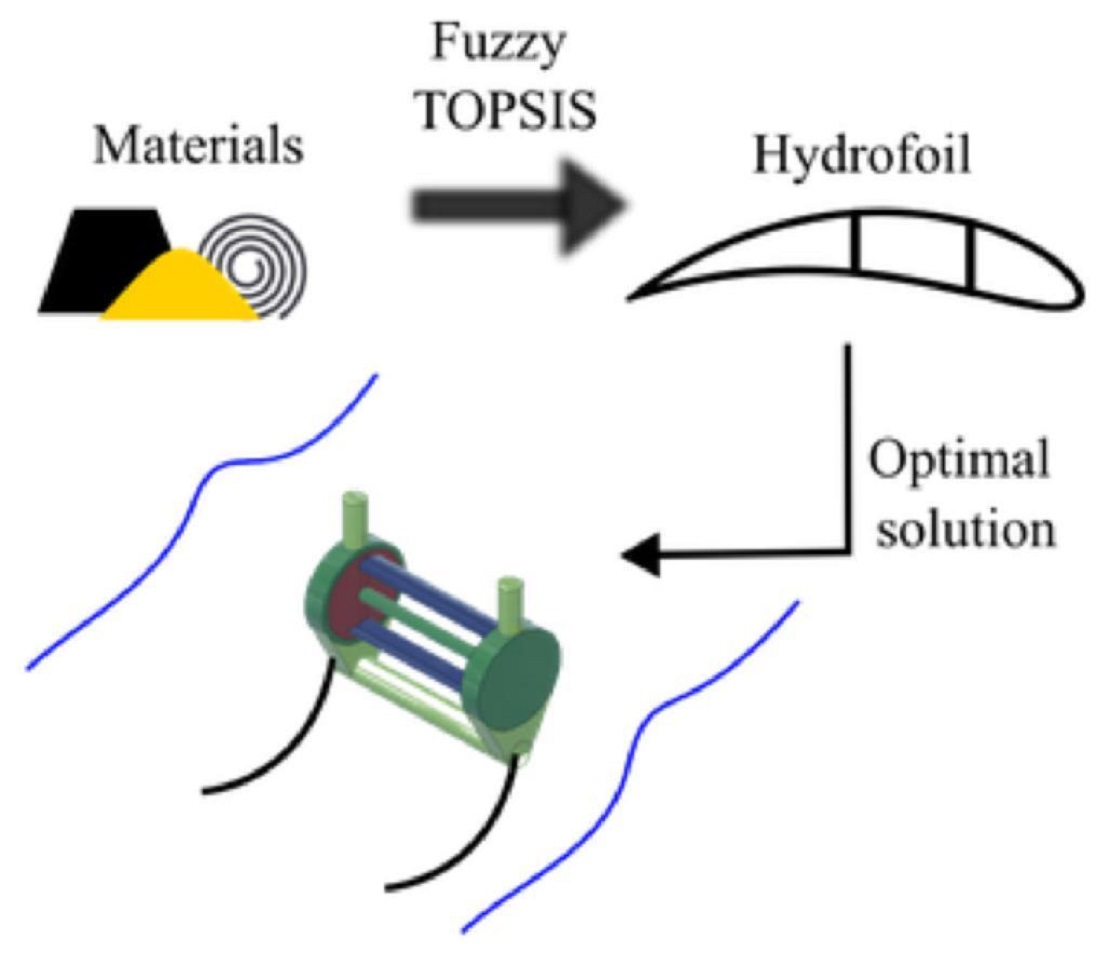
2.1. Material Selection Framework
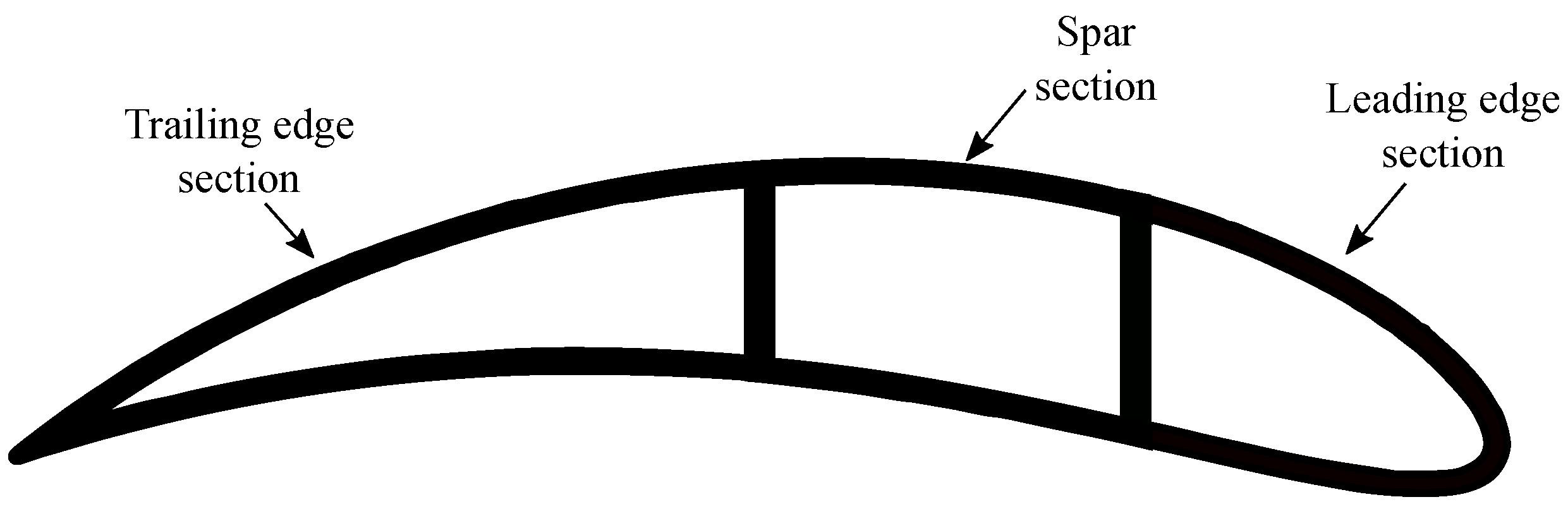
2.2. Lift-Based WEC
3. Construction of Decision-Making Framework
3.1. Multi-Criteria Decision-Making
3.2. Fuzzy Logic
3.3. Decision Matrix Formulation
4. Key Criteria for Material Selection
4.1. Structural Reliability Based on FMECA
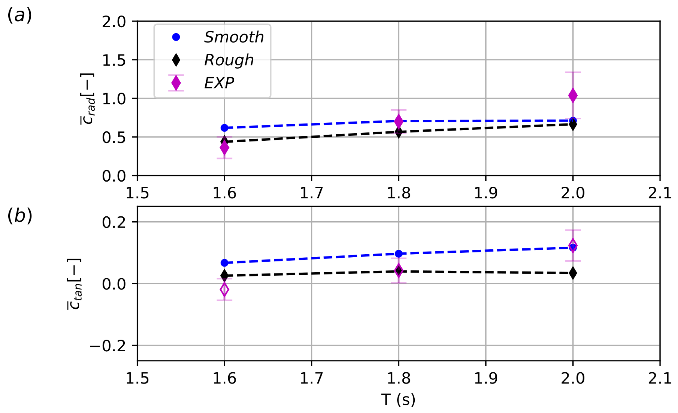
4.2. Hydrodynamic Efficiency
4.3. Offshore Maintainability

| Material | Industry Experience | Corrosion Resistance | Erosion Resistance | Offshore Maintainability |
|---|---|---|---|---|
| Offshore steel (S355) | High | Average | High | Average |
| Offshore steel (Duplex 1.4462) | High | High | High | High |
| Aluminium alloy Al-Mg | Very high | Very High | High | Very High |
| Composite—CFRP | Low | Very High | Average | Low |
| Composite—GFRP | Low | Very High | Very low | Very Low |
4.4. Cost of Manufacturing
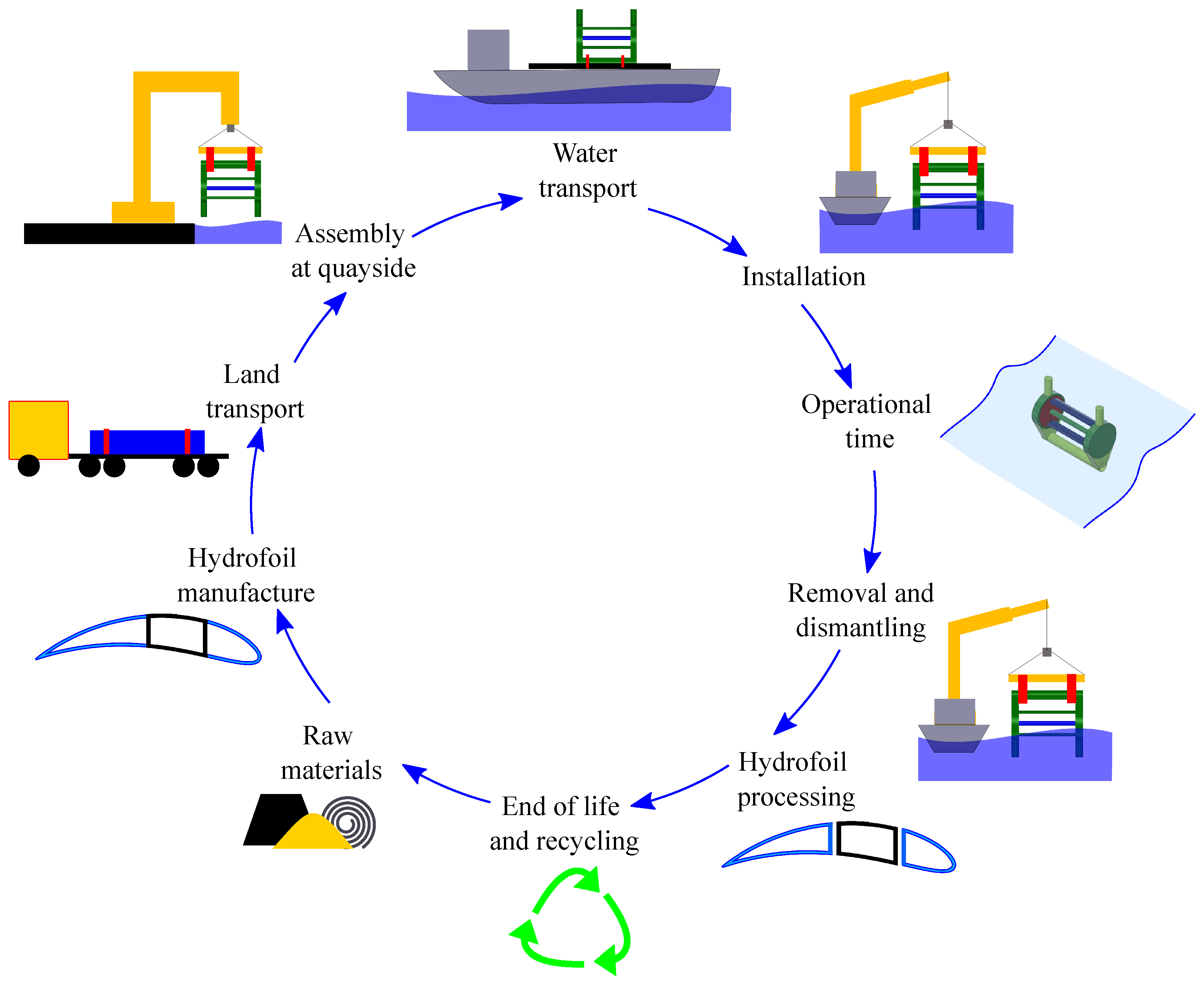
4.5. Environmental Impact, Manufacturability and Recyclability
5. Results and Discussion
6. Conclusions
Supplementary Materials
Author Contributions
Funding
Data Availability Statement
Acknowledgments
Conflicts of Interest
Abbreviations
| AP | Action priority |
| FMEA | Failure Mode and Effect Analysis |
| FMECA | Failure Mode, Effect, and Criticality Analysis |
| GFRP | Glass fiber reinforced polymer |
| CFRP | Carbon fiber reinforced polymer |
| GHG | Greenhouse gas |
| VH | Very high |
| H | High |
| AV | Average |
| L | Low |
| VL | Very low |
| HATT | Horizontal axis tidal turbine |
| HH | Human Health |
| MCDM | Multi-criteria Decision-Making |
| O&M | Operation and maintenance |
| OPEX | OPerational EXpenditure |
| PTO | Power Take-off |
| TOPSIS | Technique for Order of Preference by Similarity to Ideal Solution |
| TRL | Technology readiness level |
| VATT | Vertical axis tidal turbine |
| WEC | Wave Energy Converter |
References
- News Release: 2023 NREL Industry Growth Forum Presenters Set to Pitch to Interested Cleantech Investors. Available online: https://www.nrel.gov/news/press/2023/news-release-2023-nrel-industry-growth-forum-presenters-set-to-pitch-to-interested-cleantech-investors.html (accessed on 2 October 2023).
- McNatt, J.C.; Retzler, C.H. The performance of the Mocean M100 wave energy converter described through numerical and physical modelling. Int. Mar. Energy J. 2020, 3, 11–19. [Google Scholar] [CrossRef]
- Jin, S.; Greaves, D. Wave energy in the UK: Status review and future perspectives. Renew. Sustain. Energy Rev. 2021, 143, 110932. [Google Scholar] [CrossRef]
- Siegel, S.G. Numerical benchmarking study of a Cycloidal Wave Energy Converter. Renew. Energy 2019, 134, 390–405. [Google Scholar] [CrossRef]
- Arredondo-Galeana, A.; Olbert, G.; Shi, W.; Brennan, F. Near wake hydrodynamics and structural design of a single foil cycloidal rotor in regular waves. Renew. Energy 2023, 206, 1020–1035. [Google Scholar] [CrossRef]
- Ermakov, A.; Thiebaut, F.; Payne, G.S.; Ringwood, J.V. Validation of a control-oriented point vortex model for a cyclorotor-based wave energy device. J. Fluids Struct. 2023, 119, 103875. [Google Scholar] [CrossRef]
- Olbert, G.; Abdel-Maksoud, M. High-fidelity modelling of lift-based wave energy converters in a numerical wave tank. Appl. Energy 2023, 347, 121460. [Google Scholar] [CrossRef]
- Siegel, S. Wave climate scatter performance of a cycloidal wave energy converter. Appl. Ocean Res. 2014, 48, 331–343. [Google Scholar] [CrossRef]
- Ermakov, A.; Marie, A.; Ringwood, J.V. Optimal control of pitch and rotational velocity for a cyclorotor wave energy device. IEEE Trans. Sustain. Energy 2022, 13, 1631–1640. [Google Scholar] [CrossRef]
- Maria-Arenas, A.; Garrido, A.J.; Rusu, E.; Garrido, I. Control Strategies Applied to Wave Energy Converters: State of the Art. Energies 2019, 12, 3115. [Google Scholar] [CrossRef]
- Katsidoniotaki, E.; Psarommatis, F.; Göteman, M. Digital Twin for the Prediction of Extreme Loads on a Wave Energy Conversion System. Energies 2022, 15, 5464. [Google Scholar] [CrossRef]
- Arredondo-Galeana, A.; Ermakov, A.; Shi, W.; Ringwood, J.V.; Brennan, F. Control Strategies for Power Enhancement and Fatigue Damage Mitigation of Wave Cycloidal Rotors; SSRN: Rochester, NY, USA, 2022. [Google Scholar] [CrossRef]
- Dezert, J.; Tchamova, A.; Han, D.; Tacnet, J.M. The SPOTIS Rank Reversal Free Method for Multi-Criteria Decision-Making Support. In Proceedings of the 2020 IEEE 23rd International Conference on Information Fusion (FUSION), Rustenburg, South Africa, 6–9 July 2020; pp. 1–8. [Google Scholar] [CrossRef]
- Bączkiewicz, A.; Kizielewicz, B.; Shekhovtsov, A.; Yelmikheiev, M.; Kozlov, V.; Sałabun, W. Comparative Analysis of Solar Panels with Determination of Local Significance Levels of Criteria Using the MCDM Methods Resistant to the Rank Reversal Phenomenon. Energies 2021, 14, 5727. [Google Scholar] [CrossRef]
- Sałabun, W.; Karczmarczyk, A.; Wątróbski, J.; Jankowski, J. Handling Data Uncertainty in Decision Making with COMET. In Proceedings of the 2018 IEEE Symposium Series on Computational Intelligence (SSCI), Bengaluru, India, 18–21 November 2018; pp. 1478–1484. [Google Scholar] [CrossRef]
- Kizielewicz, B.; Kołodziejczyk, J. Effects of the selection of characteristic values on the accuracy of results in the COMET method. Procedia Comput. Sci. 2020, 176, 3581–3590. [Google Scholar] [CrossRef]
- Stoilova, S.D. A multi-criteria approach for evaluating the urban transport technologies by using SIMUS method. IOP Conf. Ser. Mater. Sci. Eng. 2019, 618, 012059. [Google Scholar] [CrossRef]
- Bączkiewicz, A.; Wątróbski, J. Multi-Criteria Temporal Assessment of Afordable and Clean Energy Systems in European Countries Using the DARIA-TOPSIS Method. Procedia Comput. Sci. 2022, 207, 4442–4453. [Google Scholar] [CrossRef]
- Lootsma, F.; Meisner, J.; Schellemans, F. Multi-criteria decision analysis as an aid to the strategic planning of Energy R&D. Eur. J. Oper. Res. 1986, 25, 216–234. [Google Scholar] [CrossRef]
- Mutikanga, H.E.; Sharma, S.K.; Vairavamoorthy, K. Multi-criteria Decision Analysis: A Strategic Planning Tool for Water Loss Management. Water Resour. Manag. 2011, 25, 3947–3969. [Google Scholar] [CrossRef]
- Radmehr, A.; Bozorg-Haddad, O.; Loáiciga, H.A. Integrated strategic planning and multi-criteria decision-making framework with its application to agricultural water management. Sci. Rep. 2022, 12, 8406. [Google Scholar] [CrossRef]
- Tamošaitienė, J.; Zavadskas, E.K.; Šileikaitė, I.; Turskis, Z. A Novel Hybrid MCDM Approach for Complicated Supply Chain Management Problems in Construction. Procedia Eng. 2017, 172, 1137–1145. [Google Scholar] [CrossRef]
- Sufiyan, M.; Haleem, A.; Khan, S.; Khan, M.I. Evaluating food supply chain performance using hybrid fuzzy MCDM technique. Sustain. Prod. Consum. 2019, 20, 40–57. [Google Scholar] [CrossRef]
- Mzougui, I.; Carpitella, S.; Certa, A.; El Felsoufi, Z.; Izquierdo, J. Assessing Supply Chain Risks in the Automotive Industry through a Modified MCDM-Based FMECA. Processes 2020, 8, 579. [Google Scholar] [CrossRef]
- Yeh, T.M.; Pai, F.Y.; Liao, C.W. Using a hybrid MCDM methodology to identify critical factors in new product development. Neural Comput. Appl. 2014, 24, 957–971. [Google Scholar] [CrossRef]
- Ilgin, M.A.; Gupta, S.M.; Battaïa, O. Use of MCDM techniques in environmentally conscious manufacturing and product recovery: State of the art. J. Manuf. Syst. 2015, 37, 746–758. [Google Scholar] [CrossRef]
- García-Orozco, S.; Vargas-Gutiérrez, G.; Ordóñez-Sánchez, S.; Silva, R. Using Multi-Criteria Decision Making in Quality Function Deployment for Offshore Renewable Energies. Energies 2023, 16, 6533. [Google Scholar] [CrossRef]
- DNVGL. DNV OSS-312—Certification of Tidal and Wave Energy Converters. 2012. Available online: https://standards.globalspec.com/std/1601838/dnv-oss-312 (accessed on 2 October 2023).
- Kenny, C.; Findlay, D.; Lazakis, I.; Shek, J.; Thies, P. Development of a condition monitoring system for an articulated wave energy converter by FMEA. Risk, Reliability and Safety: Innovating Theory and Practice; Walls, L., Revie, M., Bedford, T., Eds.; Taylor & Francis Group: Glasgow, UK; London, UK, 2016; pp. 1151–1157. [Google Scholar]
- Kenny, C.J.; Findlay, D.; Thies, P.R.; Shek, J.; Lazakis, I. Lessons learned from 3 years of failure: Validating an FMEA with historical failure data. In Proceedings of the 12th European Wave and Tidal Energy Conference, Cork, Ireland, 27 August–1 September 2017. [Google Scholar]
- Okoro, U.; Kolios, A.; Cui, L. Multi-criteria risk assessment approach for components risk ranking—The case study of an offshore wave energy converter. Int. J. Mar. Energy 2017, 17, 21–39. [Google Scholar] [CrossRef]
- Coe, R.G.; Yu, Y.H.; Van Rij, J. A Survey of WEC Reliability, Survival and Design Practices. Energies 2018, 11, 4. [Google Scholar] [CrossRef]
- Fernández-Chozas, J.; Tetu, A.; Arredondo-Galeana, A. Parametric Cost Model for the Initial Techno-Economic Assessment of Lift-Force Based Wave Energy Converters. In Proceedings of the 14th European Wave and Tidal Energy Conference, Plymouth, UK, 5–9 September 2021. [Google Scholar]
- Bastos, P.; Devoy-McAuliffe, F.; Arredondo-Galeana, A.; Chozas, J.; Lamont-Kane, P.; Vinagre, P.A. Life Cycle Assessment of a wave energy device—LiftWEC. In Proceedings of the 15th European Wave and Tidal Energy Conference, Bilbao, Spain, 3–7 September 2023. [Google Scholar]
- Arredondo-Galeana, A.; Lamont-Kane, P.; Shi, W.; Folley, M.; Brennan, F. A probabilistic fatigue framework for fatigue damage of lift based wave energy converters. In Proceedings of the 15th European Wave and Tidal Energy Conference, Bilbao, Spain, 3–7 September 2023. [Google Scholar]
- Developing Innovative Strategies to Extract Ocean Wave Energy. LiftWEC. Available online: https://liftwec.com (accessed on 24 June 2023).
- Hwang, C.L.; Yoon, K. Methods for multiple attribute decision making. In Multiple Attribute Decision Making: Methods and Applications A State-of-the-Art Survey; Springer: Berlin/Heidelberg, Germany, 1981; pp. 58–191. [Google Scholar] [CrossRef]
- Yoon, K. A Reconciliation Among Discrete Compromise Solutions. J. Oper. Res. Soc. 1987, 38, 277–286. [Google Scholar] [CrossRef]
- Hwang, C.L.; Lai, Y.J.; Liu, T.Y. A new approach for multiple objective decision making. Comput. Oper. Res. 1993, 20, 889–899. [Google Scholar] [CrossRef]
- Wang, T.C.; Chang, T.H. Application of TOPSIS in evaluating initial training aircraft under a fuzzy environment. Expert Syst. Appl. 2007, 33, 870–880. [Google Scholar] [CrossRef]
- Cavallaro, F. Fuzzy TOPSIS approach for assessing thermal-energy storage in concentrated solar power (CSP) systems. Appl. Energy 2010, 87, 496–503. [Google Scholar] [CrossRef]
- Şengül, Ü.; Eren, M.; Eslamian Shiraz, S.; Gezder, V.; Şengül, A.B. Fuzzy TOPSIS method for ranking renewable energy supply systems in Turkey. Renew. Energy 2015, 75, 617–625. [Google Scholar] [CrossRef]
- Nădăban, S.; Dzitac, S.; Dzitac, I. Fuzzy TOPSIS: A General View. Procedia Comput. Sci. 2016, 91, 823–831. [Google Scholar] [CrossRef]
- Yadav, V.; Karmakar, S.; Kalbar, P.P.; Dikshit, A. PyTOPS: A Python based tool for TOPSIS. SoftwareX 2019, 9, 217–222. [Google Scholar] [CrossRef]
- Karahalios, H. The application of the AHP-TOPSIS for evaluating ballast water treatment systems by ship operators. Transp. Res. Part D Transp. Environ. 2017, 52, 172–184. [Google Scholar] [CrossRef]
- Ross, H.H.; Schinas, O. Empirical evidence of the interplay of energy performance and the value of ships. Ocean Eng. 2019, 190, 106403. [Google Scholar] [CrossRef]
- Olson, D. Comparison of weights in TOPSIS models. Math. Comput. Model. 2004, 40, 721–727. [Google Scholar] [CrossRef]
- Wang, T.C.; Lee, H.D. Developing a fuzzy TOPSIS approach based on subjective weights and objective weights. Expert Syst. Appl. 2009, 36, 8980–8985. [Google Scholar] [CrossRef]
- Scheu, M.N.; Tremps, L.; Smolka, U.; Kolios, A.; Brennan, F. A systematic Failure Mode Effects and Criticality Analysis for offshore wind turbine systems towards integrated condition based maintenance strategies. Ocean Eng. 2019, 176, 118–133. [Google Scholar] [CrossRef]
- Leimeister, M.; Kolios, A. A review of reliability-based methods for risk analysis and their application in the offshore wind industry. Renew. Sustain. Energy Rev. 2018, 91, 1065–1076. [Google Scholar] [CrossRef]
- New AIAG & VDA FMEA Handbook Potential Failure Mode Effects Analysis, FMEA. Available online: https://www.aiag.org/quality/automotive-core-tools/fmea (accessed on 19 August 2021).
- Sorrentino, S.; Mecozzi, E.; Lecca, M. Fatigue Behaviour of High-Strength Steel-Welded Joints in Offshore and Marine Systems (FATHOMS); Publications Office of the EU: Luxembourg, 2010. [Google Scholar] [CrossRef]
- DNV. DNVGL-RP-C203: Fatigue Design of Offshore Steel Structures. 2019. Available online: https://www.dnv.com/oilgas/download/dnv-rp-c203-fatigue-design-of-offshore-steel-structures.html (accessed on 2 October 2023).
- Smith, W.F. Principles of Materials Science and Engineering; McGraw-Hill: New York, NY, USA, 1986. [Google Scholar]
- Lewis, K.W. The Cumulative Effects of Roughness and Reynolds Number on NACA 0015 Airfoil Section Characteristics. Master’s Thesis, Texas Tech University, Lubbock, TX, USA, 1984. [Google Scholar]
- Walker, J.; Green, R.; Gillies, E.; Phillips, C. The effect of a barnacle-shaped excrescence on the hydrodynamic performance of a tidal turbine blade section. Ocean Eng. 2020, 217, 107849. [Google Scholar] [CrossRef]
- Im, H.; Kim, B. Numerical study on the effect of blade surface deterioration by erosion on the performance of a large wind turbine. J. Renew. Sustain. Energy 2019, 11, 063308. [Google Scholar] [CrossRef]
- López, J.C.; Kolios, A.; Wang, L.; Chiachio, M. A wind turbine blade leading edge rain erosion computational framework. Renew. Energy 2023, 203, 131–141. [Google Scholar] [CrossRef]
- Pugh, K.; Nash, J.; Reaburn, G.; Stack, M. On analytical tools for assessing the raindrop erosion of wind turbine blades. Renew. Sustain. Energy Rev. 2021, 137, 110611. [Google Scholar] [CrossRef]
- Batten, W.; Bahaj, A.; Molland, A.; Chaplin, J. The prediction of the hydrodynamic performance of marine current turbines. Renew. Energy 2008, 33, 1085–1096. [Google Scholar] [CrossRef]
- Song, S.; Demirel, Y.K.; Atlar, M.; Shi, W. Prediction of the fouling penalty on the tidal turbine performance and development of its mitigation measures. Appl. Energy 2020, 276, 115498. [Google Scholar] [CrossRef]
- Walker, J.M.; Flack, K.A.; Lust, E.E.; Schultz, M.P.; Luznik, L. Experimental and numerical studies of blade roughness and fouling on marine current turbine performance. Renew. Energy 2014, 66, 257–267. [Google Scholar] [CrossRef]
- Priegue, L.; Stoesser, T. The influence of blade roughness on the performance of a vertical axis tidal turbine. Int. J. Mar. Energy 2017, 17, 136–146. [Google Scholar] [CrossRef]
- Sezen, S.; Uzun, D.; Ozyurt, R.; Turan, O.; Atlar, M. Effect of biofouling roughness on a marine propeller’s performance including cavitation and underwater radiated noise (URN). Appl. Ocean Res. 2021, 107, 102491. [Google Scholar] [CrossRef]
- Vedaprakash, L.; Dineshram, R.; Ratnam, K.; Lakshmi, K.; Jayaraj, K.; Mahesh Babu, S.; Venkatesan, R.; Shanmugam, A. Experimental studies on the effect of different metallic substrates on marine biofouling. Colloids Surfaces B Biointerfaces 2013, 106, 1–10. [Google Scholar] [CrossRef]
- Muthukumar, T.; Aravinthan, A.; Lakshmi, K.; Venkatesan, R.; Vedaprakash, L.; Doble, M. Fouling and stability of polymers and composites in marine environment. Int. Biodeterior. Biodegrad. 2011, 65, 276–284. [Google Scholar] [CrossRef]
- Smith, D.D.J. Chapter 11—Design and assurance techniques. In Reliability, Maintainability and Risk, 10th ed.; Smith, D.D.J., Ed.; Butterworth-Heinemann: Oxford, UK, 2022; pp. 195–206. [Google Scholar] [CrossRef]
- Gardner, L.; Cruise, R.B.; Sok, C.P.; Krishnan, K.; Ministro Dos Santos, J. Life-cycle costing of metallic structures. Proc. Inst. Civ. Eng.-Eng. Sustain. 2007, 160, 167–177. [Google Scholar] [CrossRef]
- Wahab, D.; Blanco-Davis, E.; Ariffin, A.; Wang, J. A review on the applicability of remanufacturing in extending the life cycle of marine or offshore components and structures. Ocean Eng. 2018, 169, 125–133. [Google Scholar] [CrossRef]
- Cevasco, D.; Koukoura, S.; Kolios, A. Reliability, availability, maintainability data review for the identification of trends in offshore wind energy applications. Renew. Sustain. Energy Rev. 2021, 136, 110414. [Google Scholar] [CrossRef]
- Yabuki, A. Particle-induced damage and subsequent healing of materials: Erosion, corrosion and self-healing coatings. Adv. Powder Technol. 2011, 22, 303–310. [Google Scholar] [CrossRef]
- Higgins, P.; Foley, A. The evolution of offshore wind power in the United Kingdom. Renew. Sustain. Energy Rev. 2014, 37, 599–612. [Google Scholar] [CrossRef]
- Vargel, C. Chapter D.1—Freshwater. In Corrosion of Aluminium; Vargel, C., Ed.; Elsevier: Amsterdam, The Netherlands, 2004; pp. 299–327. [Google Scholar] [CrossRef]
- Gńdara, M.J.F. Aluminium: The metal of choice. Mater. Technol. 2013, 47, 261–265. [Google Scholar]
- Miyazaki, N. Solid particle erosion of composite materials: A critical review. J. Compos. Mater. 2016, 50, 3175–3217. [Google Scholar] [CrossRef]
- Tewari, U.; Harsha, A.; Häger, A.; Friedrich, K. Solid particle erosion of carbon fibre– and glass fibre–epoxy composites. Compos. Sci. Technol. 2003, 63, 549–557. [Google Scholar] [CrossRef]
- Walker, S.; Howell, R.; Hodgson, P.; Griffin, A. Tidal energy machines: A comparative life cycle assessment study. Proc. Inst. Mech. Eng. Part M J. Eng. Marit. Environ. 2015, 229, 124–140. [Google Scholar] [CrossRef]
- Walker, S.R.; Thies, P.R. A life cycle assessment comparison of materials for a tidal stream turbine blade. Appl. Energy 2022, 309, 118353. [Google Scholar] [CrossRef]
- Mishnaevsky, L.; Branner, K.; Petersen, H.N.; Beauson, J.; McGugan, M.; Sørensen, B.F. Materials for Wind Turbine Blades: An Overview. Materials 2017, 10, 1285. [Google Scholar] [CrossRef]
- Veers, P.S.; Ashwill, T.D.; Sutherland, H.J.; Laird, D.L.; Lobitz, D.W.; Griffin, D.A.; Mandell, J.F.; Musial, W.D.; Jackson, K.; Zuteck, M.; et al. Trends in the Design, Manufacture and Evaluation of Wind Turbine Blades. Wind Energy 2003, 6, 245–259. [Google Scholar] [CrossRef]
- Yang, Y.; Boom, R.; Irion, B.; van Heerden, D.J.; Kuiper, P.; de Wit, H. Recycling of composite materials. Chem. Eng. Process. Process Intensif. 2012, 51, 53–68. [Google Scholar] [CrossRef]
- Arredondo-Galeana, A.; Brennan, F. Floating Offshore Vertical Axis Wind Turbines: Opportunities, Challenges and Way Forward. Energies 2021, 14, 8000. [Google Scholar] [CrossRef]
- Liu, P.; Barlow, C.Y. The environmental impact of wind turbine blades. IOP Conf. Ser. Mater. Sci. Eng. 2016, 139, 012032. [Google Scholar] [CrossRef]
- Ashby, M.F.; Cebon, D. Materials selection in mechanical design. J. Phys. IV 1993, 3, C7-1–C7-9. [Google Scholar] [CrossRef]
- Jensen, J.; Skelton, K. Wind turbine blade recycling: Experiences, challenges and possibilities in a circular economy. Renew. Sustain. Energy Rev. 2018, 97, 165–176. [Google Scholar] [CrossRef]
- Murray, R.E.; Roadman, J.; Beach, R. Fusion joining of thermoplastic composite wind turbine blades: Lap-shear bond characterization. Renew. Energy 2019, 140, 501–512. [Google Scholar] [CrossRef]
- Morini, A.A.; Ribeiro, M.J.; Hotza, D. Carbon footprint and embodied energy of a wind turbine blade—A case study. Int. J. Life Cycle Assess. 2021, 26, 1177–1187. [Google Scholar] [CrossRef]
- Liu, P.; Meng, F.; Barlow, C.Y. Wind turbine blade end-of-life options: An eco-audit comparison. J. Clean. Prod. 2019, 212, 1268–1281. [Google Scholar] [CrossRef]
- Du, Y.; Zhou, S.; Jing, X.; Peng, Y.; Wu, H.; Kwok, N. Damage detection techniques for wind turbine blades: A review. Mech. Syst. Signal Process. 2020, 141, 106445. [Google Scholar] [CrossRef]
- Suzuki, T.; Takahashi, J. Prediction of energy intensity of carbon fiber reinforced plastics for mass-produced passenger cars. In Proceedings of the 9th Japan International SAMPE Symposium. Department of Environmental and Ocean Engineering, Tokyo, Japan, 29 November–2 December 2005; The University of Tokyo Japan: Tokyo, Japan, 2005. [Google Scholar]
- Granta Design. Eco-Data in CES Eco-Selector 2016 Database; Granta Design: Cambridge, UK, 2016. [Google Scholar]
- Allmark, M.; Ellis, R.; Lloyd, C.; Ordonez-Sanchez, S.; Johannesen, K.; Byrne, C.; Johnstone, C.; O’Doherty, T.; Mason-Jones, A. The development, design and characterisation of a scale model Horizontal Axis Tidal Turbine for dynamic load quantification. Renew. Energy 2020, 156, 913–930. [Google Scholar] [CrossRef]
- Payne, G.S.; Stallard, T.; Martinez, R. Design and manufacture of a bed supported tidal turbine model for blade and shaft load measurement in turbulent flow and waves. Renew. Energy 2017, 107, 312–326. [Google Scholar] [CrossRef]
- Gaurier, B.; Ordonez-Sanchez, S.; Facq, J.V.; Germain, G.; Johnstone, C.; Martinez, R.; Salvatore, F.; Santic, I.; Davey, T.; Old, C.; et al. MaRINET2 tidal energy round robin tests—Performance comparison of a horizontal axis turbine subjected to combined wave and current conditions. J. Mar. Sci. Eng. 2020, 8, 463. [Google Scholar] [CrossRef]
- Schmitt, P.; Fu, S.; Benson, I.; Lavery, G.; Ordoñez-Sanchez, S.; Frost, C.; Johnstone, C.; Kregting, L. A comparison of tidal turbine characteristics obtained from field and laboratory testing. J. Mar. Sci. Eng. 2022, 10, 1182. [Google Scholar] [CrossRef]
- Caio, A.; Davey, T.; McNatt, J.C. Preliminary hydrodynamic assessment of Mocean energy’s Blue Star WEC via fast turnaround physical model testing. In Proceedings of the 14th European Wave and Tidal Energy Conference, Plymouth, UK, 5–9 September 2021. [Google Scholar]
- Samuel, J.A.; Venugopal, V.; Retzler, C.; Ma, Q. Hydrodynamic Response of Mocean Wave Energy Converter in Extreme Waves. In Proceedings of the 15th European Wave and Tidal Energy Conference, Bilbao, Spain, 3–7 September 2023. [Google Scholar]
- Arredondo-Galeana, A.; Shi, W.; Olbert, G.; Scharf, M.; Ermakov, A.; Ringwood, J.; Brennan, F. A methodology for the structural design of LiftWEC: A wave-bladed cyclorotor. In Proceedings of the 14th European Wave and Tidal Energy Conference, Plymouth, UK, 5–9 September 2021. [Google Scholar]
- Więckowski, J.; Sałabun, W. Sensitivity analysis approaches in multi-criteria decision analysis: A systematic review. Appl. Soft Comput. 2023, 148, 110915. [Google Scholar] [CrossRef]
- Multi-Criteria Decision-Making. Available online: http://www.make-decision.it (accessed on 23 October 2023).


| Expert ID | Years of Experience | Field of Expertise |
|---|---|---|
| First author (AAG) | +10 years | Hydrodynamics and fluid–structure interactions of offshore renewable assets |
| Second author (BY) | +10 years | Structural integrity and reliability of offshore renewable assets |
| Third author (FA) | +10 years | Structural assessment of composite and steel structures |
| Fourth author (SOS) | +20 years | Materials and hydrodynamics of tidal turbines |
| Fifth author (SL) | +20 years | Structural integrity of offshore renewable assets |
| Sixth author (FB) | +30 years | Offshore engineering and structural integrity of offshore renewable assets |
| Q1 | Q2 | Q3 | Q4 | Q5 | |
|---|---|---|---|---|---|
| Candidate 1 | High | Average | High | Average | High |
| Candidate 2 | High | Average | High | High | High |
| Candidate 3 | Average | Average | Very High | Very High | Average |
| Candidate 4 | Very High | High | Average | High | High |
| Candidate 5 | High | High | Average | Average | High |
| Fuzzy Number | Linguistic Term |
|---|---|
| (1, 2, 3) | Very low |
| (2, 3.5, 5) | Low |
| (4, 5.5, 7) | Average |
| (6, 7.5, 9) | High |
| (8, 9, 10) | Very high |
| Q1 | Q2 | Q3 | Q4 | Q5 | |
|---|---|---|---|---|---|
| Candidate 1 | 6, 7.5, 9 | 4, 5.5, 7 | 6, 7.5, 9 | 4, 5.5, 7 | 6, 7.5, 9 |
| Candidate 2 | 6, 7.5, 9 | 4, 5.5, 7 | 6, 7.5, 9 | 6, 7.5, 9 | 6, 7.5, 9 |
| Candidate 3 | 4, 5.5, 7 | 4, 5.5, 7 | 8, 9, 10 | 8, 9, 10 | 4, 5.5, 7 |
| Candidate 4 | 8, 9, 10 | 6, 7.5, 9 | 4, 5.5, 7 | 6, 7.5, 9 | 6, 7.5, 9 |
| Candidate 5 | 6, 7.5, 9 | 6, 7.5, 9 | 4, 5.5, 7 | 4, 5.5, 7 | 6, 7.5, 9 |
| Key Criterion | Relevant Aspects |
|---|---|
| Structural reliability | Criticality of structural failure, yield and fatigue strength of material |
| Hydrodynamic efficiency | Corrosion, erosion and biofouling resistance of materials |
| Offshore maintainability | Industry experience, corrosion and erosion resistance of material |
| Cost of manufacturing | Waste treatment and raw material cost, embodied energy (MJ/kg) |
| Environmental impact | Recyclability, human health impact and green house gas impact |
| Weighting Factors | ||||||
|---|---|---|---|---|---|---|
| Candidate | Structural Reliability | Hydrodynamic Efficiency | Offshore Maintainability | Total Cost | Environmental Impact | Ranking |
| Offshore steel (S355) | ||||||
| Offshore steel (Duplex 1.4462) | ||||||
| Aluminium alloy Al-Mg | ||||||
| Composite—CFRP | ||||||
| Composite—GFRP | ||||||
| Failure Mode | Severity (S) | Failure Mechanism | Failure Cause | Occurrence (O) | Detection (D) | Action Priority |
|---|---|---|---|---|---|---|
| Excessive plastic deformation | H | Yielding | Multi-directional loading | M | M | H |
| VH | Yielding | Out-of-phase operational load | L | L | L | |
| H | Buckling | Misalignment and geometrical imperfections | L | H | M | |
| VH | Yielding | High bending moment midspan of hydrofoil | M | M | H | |
| VH | Brittle fracture | Low temperature and overload | VL | VH | L | |
| H | Impact loading | Dropped objects, ocean debris | L | VH | M | |
| VH | Impact loading | Mammals collision | L | M | M | |
| Cracking | H | High-cycle fatigue | High-cycle fatigue loading | M | H | H |
| M | Low cycle fatigue | Shear force and delamination | L | VH | L | |
| H | Corrosion fatigue | Pitting and cyclic loading | M | M | M | |
| Corrosion, Wear and Erosion | M | Low energy yield | Loss of suction force at leading edge | H | L | M |
| H | Electrochemical | Corrosive environment | M | L | M | |
| M | Erosion | Ocean debris | M | L | L | |
| Cavitation | VH | Localised intensive pressure | Low pressure zones and bubbles | L | L | L |
| Excessive vibration | M | Resonance | Loss of pitch control and velocity control rare sea states | L | M | L |
| Materials | Yield Strength | Fatigue Strength | Uncertainty | Structural Reliability |
|---|---|---|---|---|
| Offshore steel (S355) | Average | High | Very high | High |
| Offshore steel (Duplex 1.4462) | High | High | High | High |
| Aluminium alloy Al-Mg | Low | Very low | Very high | Average |
| Composite—CFRP | Very high | Very high | Low | High |
| Composite—GFRP | Average | Average | Very low | Low |
| Lifting Device | Surface Anomaly | Performance Drop | Reference |
|---|---|---|---|
| Wind turbine | Leading edge erosion | 2–4% | [57,58] |
| Surface erosion | 3% | [59] | |
| HATTs | Surface erosion | 6–8%, 13% | [60,61] |
| Heavy bio-fouling | 19% | [62] | |
| VATTs | Surface erosion | 40–65% | [63] |
| Marine propeller | Biofouling | 3–30% | [64] |
| Lift-based WEC | Biofouling | 30–40% | Present work |
| Material | Corrosion Resistance | Erosion Resistance | Biofouling Resistance | Hydrodynamic Efficiency |
|---|---|---|---|---|
| Offshore steel (S355) | Average | High | High | High |
| Offshore steel (Duplex 1.4462) | High | High | High | High |
| Aluminium alloy Al-Mg | Very High | High | High | Very High |
| Composite—CFRP | Very High | Average | Low | Average |
| Composite—GFRP | Very High | Very low | Average | Average |
| Waste Treatment * | Raw Material | Embodied Energy (MJ/kg) | Total Cost | |
|---|---|---|---|---|
| Offshore steel (S355) | Low | Very low | Low | Very low |
| Offshore steel (Duplex 1.4462) | Low | Very low | Low | Very low |
| Aluminium alloy Al-Mg | Very low | Average | High | Average |
| Composite—CFRP | High | Very high | Very high | Very high |
| Composite—GFRP | High | High | Low | Average |
| Material | Recyclability * | HH Impact | GHG Impact | Total Impact |
|---|---|---|---|---|
| Offshore steel (S355) | Low | Very High | Low | Low |
| Offshore steel (Duplex 1.4462) | Low | Very High | Low | Low |
| Aluminium alloy Al-Mg | Very Low | High | Average | Average |
| Composite—CFRP | High | Very Low | Very high | High |
| Composite—GFRP | Average | Low | Average | Average |
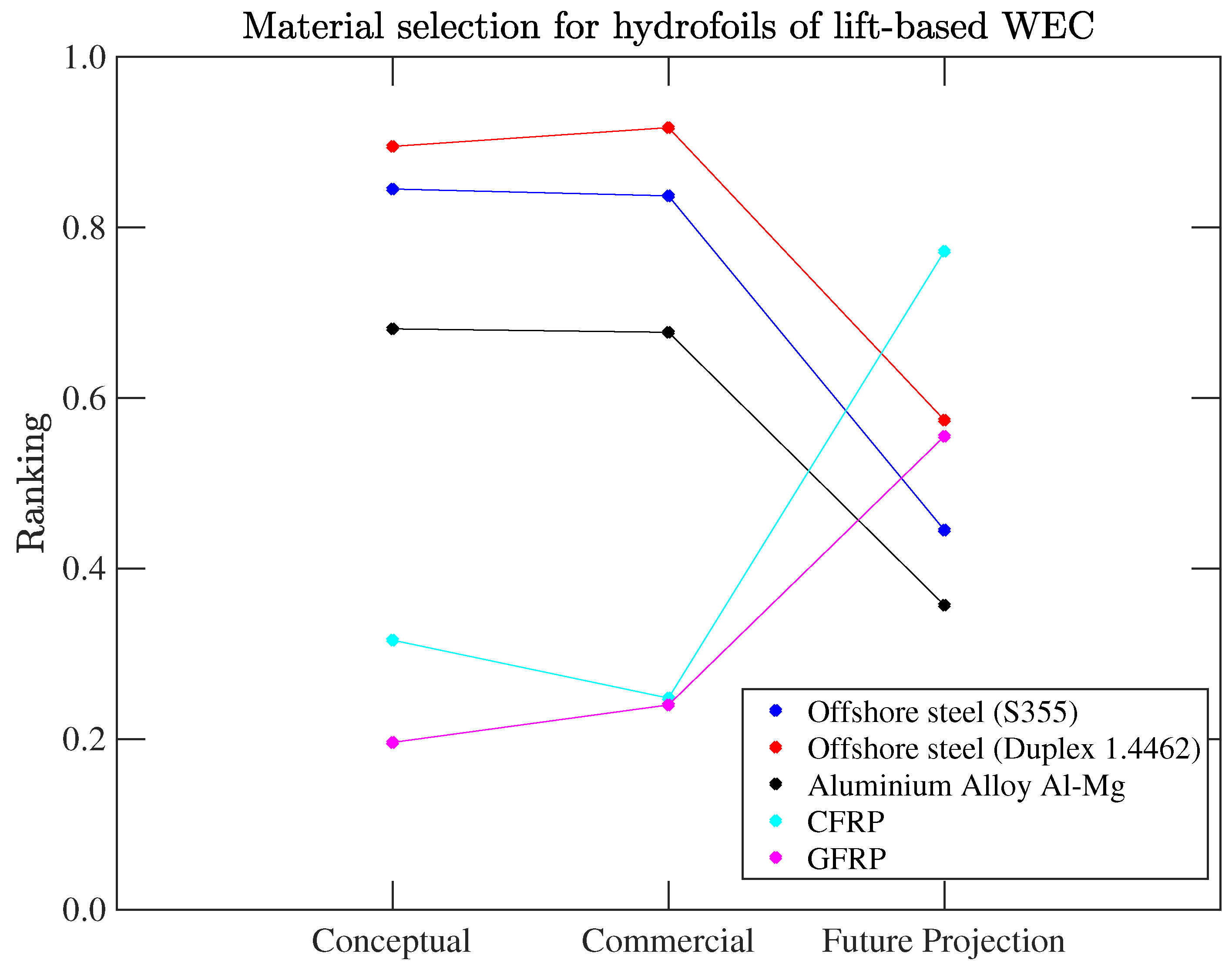
| Weighting Factors | ||||||
|---|---|---|---|---|---|---|
| VH | H | L | AV | L | ||
| Candidate/Criteria | Structural Reliability | Hydrodynamic Efficiency | Offshore Maintainability | Total Cost | Environmental Impact | Ranking |
| Offshore steel (S355) | H | H | AV | VH | H | 0.845 |
| Offshore steel (Duplex 1.4462) | H | H | H | VH | H | 0.895 |
| Aluminium alloy Al-Mg | AV | VH | VH | AV | AV | 0.681 |
| Composite—CFRP | H | AV | L | VL | L | 0.316 |
| Composite—GFRP | L | AV | VL | AV | AV | 0.196 |
| Weighting Factors | ||||||
|---|---|---|---|---|---|---|
| H | L | H | VH | AV | ||
| Candidate/Criteria | Structural Reliability | Hydrodynamic Efficiency | Offshore Maintainability | Total Cost | Environmental Impact | Ranking |
| Offshore steel (S355) | H | H | AV | VH | H | 0.837 |
| Offshore steel (Duplex 1.4462) | H | H | H | VH | H | 0.917 |
| Aluminium alloy Al-Mg | AV | VH | VH | AV | AV | 0.677 |
| Composite—CFRP | H | AV | L | VL | L | 0.248 |
| Composite—GFRP | L | AV | VL | AV | AV | 0.240 |
| Weighting Factors | ||||||
|---|---|---|---|---|---|---|
| AV | L | AV | H | VH | ||
| Candidate/Criteria | Structural Reliability | Hydrodynamic Efficiency | Offshore Maintainability | Total Cost | Environmental Impact | Ranking |
| Offshore steel (S355) | H | H | AV | AV | H | 0.445 |
| Offshore steel (Duplex 1.4462) | H | H | H | AV | H | 0.574 |
| Aluminium alloy Al-Mg | AV | VH | VH | AV | AV | 0.357 |
| Composite—CFRP | VH | AV | H | H | H | 0.772 |
| Composite—GFRP | H | AV | AV | H | H | 0.555 |
Disclaimer/Publisher’s Note: The statements, opinions and data contained in all publications are solely those of the individual author(s) and contributor(s) and not of MDPI and/or the editor(s). MDPI and/or the editor(s) disclaim responsibility for any injury to people or property resulting from any ideas, methods, instructions or products referred to in the content. |
© 2023 by the authors. Licensee MDPI, Basel, Switzerland. This article is an open access article distributed under the terms and conditions of the Creative Commons Attribution (CC BY) license (https://creativecommons.org/licenses/by/4.0/).
Share and Cite
Arredondo-Galeana, A.; Yeter, B.; Abad, F.; Ordóñez-Sánchez, S.; Lotfian, S.; Brennan, F. Material Selection Framework for Lift-Based Wave Energy Converters Using Fuzzy TOPSIS. Energies 2023, 16, 7324. https://doi.org/10.3390/en16217324
Arredondo-Galeana A, Yeter B, Abad F, Ordóñez-Sánchez S, Lotfian S, Brennan F. Material Selection Framework for Lift-Based Wave Energy Converters Using Fuzzy TOPSIS. Energies. 2023; 16(21):7324. https://doi.org/10.3390/en16217324
Chicago/Turabian StyleArredondo-Galeana, Abel, Baran Yeter, Farhad Abad, Stephanie Ordóñez-Sánchez, Saeid Lotfian, and Feargal Brennan. 2023. "Material Selection Framework for Lift-Based Wave Energy Converters Using Fuzzy TOPSIS" Energies 16, no. 21: 7324. https://doi.org/10.3390/en16217324