Article

Enhancement Effect of a Diamond Network on the Flow Boiling Heat Transfer Characteristics of a Diamond/Cu Heat Sink

1
State Key Laboratory of Nonferrous Metals and Processes, GRINM Group Co., Ltd., Beijing 100088, China
2
GRIMAT Engineering Institute Co., Ltd., Beijing 101407, China
3
General Research Institute for Nonferrous Metals, Beijing 100088, China
*
Authors to whom correspondence should be addressed.
Energies 2023, 16(21), 7228; https://doi.org/10.3390/en16217228
Submission received: 14 August 2023 / Revised: 22 September 2023 / Accepted: 3 October 2023 / Published: 24 October 2023

Abstract

:
The use of a micro heat sink is an effective means of solving the problem of high-power chip heat dissipation. Diamond/Cu composites exhibit high thermal conductivity and a linear thermal expansion coefficient that is compatible with semiconductor materials, rendering them ideal micro heat sink materials. The aim of this study was to fabricate diamond/Cu and Cu separately as heat sinks and subject them to flow boiling heat transfer experiments. The results indicate that the diamond/Cu heat sink displayed a decrease in wall superheat of 10.2–14.5 °C and an improvement in heat transfer coefficient of 38–51% compared with the Cu heat sink under identical heat fluxes. The heat sink also exhibits enhanced thermal uniformity. Secondary diamond particles are incorporated into the gaps of the main diamonds, thereby constructing a three-dimensional heat conduction network within the composite material. The diamond network enhances the internal heat flux of the material while also creating more nucleation sites on the surface. These increase the boiling intensity of the diamond/Cu heat sink, leading to better heat transfer performance. By combining the transient thermal model with computational fluid dynamics, a heat transfer model based on the diamond/Cu heat sink is proposed. The efficient heat dissipation capability of diamond/Cu heat sinks can lower the working temperature of microelectronic devices, thereby improving device performance and reliability during operation.

1. Introduction

With the development of electronic information technology, electronic devices are demonstrating a trend toward high frequency, high speed, high integration, and miniaturization [1,2,3]. The heat generated by electronic devices per unit area is rapidly increasing, and the large amount of heat produced severely affects the stability and reliability of electronic devices. More than 55% of electronic device failures are caused by heat dissipation issues related to temperature [4,5].
In the face of increasingly severe heat dissipation issues, the main solution is to develop efficient cooling methods [6,7,8,9]. The closer the heat sink is to the chip, the higher its heat dissipation efficiency, resulting in a more significant energy-saving effect. Materials with a low coefficient of linear thermal expansion (CLTE), such as W-Cu, Mo-Cu, SiC/Al, C/Cu, diamond/Cu, and diamond, have been extensively investigated for their compatibility with semiconductor materials in terms of the thermal conductivity near the chip area [10,11]. In addition to enhancing thermal conductivity, introducing thermal convection to improve heat dissipation efficiency is another important approach [12,13,14,15]. This approach involves increasing the heat transfer through convection to augment the overall cooling effect. Indeed, techniques such as the use of cold plates and microchannel heat sinks (MCHSs) utilize heat convection to enhance heat transfer capabilities [16,17]. One particular area of research focuses on heat sinks that utilize the latent heat of phase change to dissipate large amounts of heat [18]. These heat sinks aim to take advantage of the high heat transfer capacity associated with phase-change processes, such as boiling or evaporation, to achieve efficient cooling [19,20]. When facing the demands of miniaturization and high heat flux for heat dissipation, the optimal solution is to combine MCHSs with phase-change cooling. Previous research efforts have primarily focused on the design of microchannel structures [21,22,23,24], with limited studies on the influence of materials on phase-change micro heat sinks. Researchers commonly use metal materials (copper and aluminum) to fabricate heat sinks [24,25]. The high CLTE of metal materials presents a significant disparity with the CLTE of semiconductor materials, making them unsuitable for heat transfer applications near the chip. Qi [26] and Yang [27] proposed the use of diamond thin films as a material for heat sinks. Compared with aluminum MCHSs, diamond MCHSs exhibited an improved heat transfer coefficient of 37% to 73% and higher stability. However, diamond thin film as a material presents challenges in processing, a limited thickness, and an inability to cater to various usage scenarios. Diamond/Cu composites have high thermal conductivity (650–850 W/mK) and a CLTE (3.8–5.8 × 10⁻⁶/K) that matches that of semiconductor materials [28,29,30,31]. Moreover, diamond/Cu composites possess better processability and can be manufactured in larger volumes than diamond thin films. These characteristics make diamond/Cu composite heat sinks promising for addressing high thermal loads.
To meet the requirement of high thermal conductivity, diamond/Cu composites can be enhanced by incorporating diamond particles of various sizes. Every [32] proposed a theoretical model called differential effective medium (DEM), which can effectively establish a realistic model for high-content diamond composites. Molian-Jordá [33,34] utilized the DEM model to simulate the thermal conductivity of bimodal diamond, and the simulated values closely matched the experimental values. Given that their CLTE closely matches that of semiconductor materials, diamond/Cu composites can theoretically be applied in the field of heat transfer for semiconductor chip packaging [35]. Heat sinks fabricated by utilizing the high thermal conductivity of diamond/Cu composites also exhibit excellent thermal dissipation performance near the chip. However, few have studied the heat transfer performance of diamond/Cu composites in relation to their inherent composite material properties. The impact of the network structure formed by high-thermal-conductivity particles within a composite material on the flow boiling performance is a novel scientific element. Unlike previous studies on the thermal conductivity of network structures in materials science, this research represents a unique and interdisciplinary study that combines heat convection with materials science.
In this study, a complex heat conduction network was constructed within a composite material by incorporating diamond particles of two size ranges. This approach ensures that the composites exhibit a high thermal conductivity. The composite was then processed into a micro heat sink for flow boiling heat transfer experiments. This experiment combined the unique material microstructure of diamond/Cu composites with a theoretical model designed specifically for flow boiling heat transfer experiments, providing guidance for the application of diamond/Cu composites in the field of flow boiling heat transfer.

2. Experimental Setup

2.1. Flow Loop

Figure 1 shows the schematic of the experimental flow loop system. All components of the entire setup are connected using stainless steel pipes, forming a closed-loop system. Deionized water flows out of the liquid reservoir and is then pumped into a flow meter by a gear pump before entering the preheater. The preheater is responsible for heating the deionized water to the desired temperature for experimental purposes. After passing through the preheater, the deionized water enters the testing section. The temperature and pressure of the fluid at the inlet and outlet of the test section are monitored using two K-type thermocouples and two pressure transducers (Yokogawa EJA530E, Musashino, Tokyo). The heating power of the cartridge heaters in the testing section is controlled by a DC power supply unit (ITECH IT6513A, New Taipei City, Taiwan), and the heating temperature is monitored by 15 T-type thermocouples, which are distributed across three layers. The K-type thermocouples used in this experiment were manufactured by OMEGA (model: TJ36-CPSS-316, Dublin, Ireland), with an exterior diameter of 4.78 mm. The T-type thermocouples, also manufactured by OMEGA (model: TMTSS-032), had an exterior diameter of 0.8 mm. All measurement instruments were calibrated before the experiment. The fluid flows back to the liquid reservoir after passing through the condenser.
Figure 2 illustrates the decomposition diagram of the test section and presents a schematic representation of the heat sink in the present study. The test section comprises seven main components: a cover plate, an upper aluminum plate, a polytetrafluoroethylene (PTFE) housing, a copper substrate with a heat sink, a heat-resistant insulation board, and a lower aluminum plate. The cover plate is made of polysulfone and secured to the upper aluminum plate using bolts. The cover plate is designed with liquid inlet and outlet ports and spaces for liquid flow. Fifteen holes are distributed on both the PTFE housing and the copper substrate to accommodate the insertion of thermocouples. The copper substrate is made of oxygen-free copper and connected to the micro heat sink through welding. Additionally, the copper substrate has four holes for inserting cartridge heaters. The copper substrate is completely enveloped by the PTFE housing and the bottom insulation board, reducing heat dissipation. The lower aluminum plate supports the entire structure and is securely fixed to the upper aluminum plate using bolts.

2.2. Preparation of Diamond/Cu Composite

The main diamond particles with a size of 400 μm were uniformly mixed with secondary diamond particles with a size range of 30–40 μm. The mixture was then combined with a binder, followed by vacuum drying at 450 °C for 60 min. This process resulted in the formation of a diamond network. The Cu-Cr alloy was heated to 1250 °C and poured into a mold containing the diamond network. A vertical pressure of 60 MPa was applied to force the Cu-Cr (1.0 wt% Cr) alloy to infiltrate the diamond network. The literature can be referred to for the details of the preparation process [29,30]. The volume fraction of diamond in the diamond/Cu composite was between 60% and 65%. The thermal conductivity of the diamond/Cu composite is 780 W/(m·K), the specific heat capacity is 0.47 × 10³ J/(kg·K), the density is 4.9 g/cm3, and the CLTE is 4.0 × 10⁻⁶/K. The density ρ was measured using the drainage method. The specific heat capacity c was measured using the differential scanning calorimetryDSC method. The thermal diffusivity K was measured using the laser flash method. The testing environment for the samples was maintained at 100 °C, and the measured data showed little variation within the experimental conditions. The diamond/Cu composite was processed into a heat sink with dimensions of 10 mm × 20 mm × 2 mm, as illustrated in Figure 3. The Cu heat sink was fabricated using oxygen-free copper (copper content of 99.95% and oxygen content less than 0.003%).

3. Heat Transfer Data Reduction

The specific mass flux G is fixed at 507 kg/m2s and obtained using the following equation:
G   = v ρ A A = v ρ ,
where v is the velocity of the liquid, ρ is the density of the liquid, and A is the cross-sectional area for flow (10 mm × 0.5 mm).
The unidirectional heat flux q″ provided to the testing heat sink in the experiment is calculated by using the one-dimensional Fourier’s law of heat conduction [36]:
q = λ Cu   d T d x   ,
where λCu is the thermal conductivity of the copper (380 W/mK). dT/dx represents the temperature gradient in the longitudinal direction of the copper substrate when it is being heated. This temperature gradient can be estimated using the temperature data from the three thermocouples embedded in the substrate, using a three-point backward Taylor series approximation as follows [24,36]:
d T d x     3 T 1 4 T 2 + T 3 2 Δ x   ,
where T1, T2, and T3 represent the temperatures of the thermocouples on the substrate from top to bottom, as shown in Figure 2. Δx is the distance between them and is equal to 4 mm. This approach was used by Buchling and Kandlikar [37] and Gupta and Misra [36].
The temperature of the heat-exchange surface (Tw) refers to the temperature of the heat sink surface that is in contact with the fluid. Tw can be calculated using the one-dimensional Fourier’s law of heat conduction on the basis of the temperature values obtained from the top thermocouples and q″. In this study, a soldered connection of tin between the substrate and the heat sink was used. Therefore, when calculating the thermal conductivity, the thermal resistances of the substrate, the solder layer, and the heat sink must be considered. Tw is calculated using the following equation:
T w = T 1 q   L 1 λ Cu + L T λ T + L HT λ HT   ,
where L1 is the distance between the top thermocouple and the top surface of the substrate, which is 1.5 mm. LT and λT represent the thickness and thermal conductivity of the tin solder layer, respectively. According to reference [38,39,40], the following can be assumed: LT = 0.1 mm and λT = 58 W/(m·K). LHT is the thickness of the heat sink, which is 2.0 mm. Depending on the material of the heat sink, the thermal conductivity λHT is denoted as λCu for oxygen-free copper and λdiamond/Cu for diamond/Cu.
The wall superheat ΔTsat, defined as the difference between heat-exchange surface Tw and liquid saturation temperature Tsat, is calculated using the following formula:
T sat = T w T sat   .
The heat transfer coefficient h is calculated based on the temperature of the heat-exchange surface (Tw), outlet liquid temperature Tf, and heat flux q“, using the following equation:
h   = q T w T f   .
To assess the uniformity of temperature, the temperature fluctuation amplitude σ is calculated using the equation for standard deviation. Law [41] and Deng [17] used a similar formula to calculate the pressure drop fluctuation amplitude for evaluating the flow instabilities of heat sinks:
σ =   n = 1 n   T b , n T b , n - - - -   2 n - 1   ,
where n is the amount of data collected under the working conditionsand Tb represents the temperature at the bottom of the sink.
The maximum uncertainties of the parameters in the experiment are obtained using Moffat’s uncertainty analysis method [42], as shown in Table 1.

4. Results and Discussion

4.1. Flow Boiling Heat Transfer Performance

The primary indicator for evaluating a heat sink is its heat transfer performance. Figure 4a presents the boiling curves obtained from the experimental data for diamond/Cu and Cu heat sinks under the following conditions: inlet subcooling ΔTsub = 20 °C and specific mass flux G = 507 kg/m2s. The x-axis represents the wall superheat (ΔTsat), while the y-axis represents the heat flux (q″) of the heat sink. The boiling curve of the diamond/Cu heat sink is shifted to the left and has a steeper slope than the boiling curve of the Cu heat sink. This result indicates that the diamond/Cu heat sink exhibits a greater boiling intensity than the Cu heat sink at the same q″ and effectively reduces the heat-exchange surface temperature, which is due to the higher thermal conductivity of the diamond/Cu composite and the heat conduction network created by the diamond particles within it. Figure 4b displays the experimental heat transfer coefficient curves of the two materials in the heat sink. The x-axis represents the heat flux (q″) of the heat sink, while the y-axis represents the heat transfer coefficient h. The heat transfer coefficient curve visually illustrates the heat sink’s heat transfer capacity. At a low heat flux (q″ < 480 kW/m2), the heat transfer coefficients of the two materials of the heat sink are relatively similar. However, the h of the diamond/Cu heat sink rapidly increases as the q″ increases and becomes significantly higher than that of the Cu heat sink. Compared with the Cu heat sink at the same q″, the diamond/Cu heat sink exhibits a reduction in Tw ranging from 10.2 °C to 14.5 °C. Furthermore, h was enhanced by 38% to 51%.
Another important indicator for evaluating heat sinks is their temperature distribution. The temperature uniformity can represent the stability and consistency of the heat sink operation and the heat transfer capability. The aim of this experiment was to study the thermal uniformity performance of the heat sink by calculating the temperature distribution at the bottom. Figure 5a illustrates the bottom temperature distribution along the length direction of the heat sink under different heat fluxes. The x-axis represents the temperature measurement positions. The total length of the heat sink is 20 mm, and thermocouples are placed at the following positions: 0, 5, 10, 15, and 20 mm. The y-axis represents the heat flux, while the z-axis represents the temperature at the bottom of the heat sink. The peak and overall temperatures of the Cu heat sink were consistently higher than those of the diamond/Cu heat sink, indicating that the diamond/Cu heat sink can maintain lower temperatures than the Cu heat sink across all points under the same heat flux. At a low heat flux, the temperatures of both heat sinks at all positions are similar. On one hand, the temperature at the middle section (10 mm) of the Cu heat sink rises with the heat flux, leading to an increasing temperature difference between the middle section and the two ends. On the other hand, except for the highest temperature at the 5 mm position, the temperature differences at the other four positions of the diamond/Cu heat sink are relatively small. Figure 5b illustrates the temperature--time curve of the uppermost thermocouples at different positions under high heat flux (q″ = 1610.75 kW/m2). It can be observed that, under the fixed operating conditions, the temperature variation of the thermocouple is minimal, with a fluctuation difference not exceeding 0.6 °C.This indicates that the temperature data are reliable. The diamond/Cu heat sink exhibits superior performance in terms of temperature uniformity compared with the Cu heat sink. To further quantify the temperature difference and temperature fluctuation amplitude σ between the two types of heat sinks, Figure 6 shows the temperature difference (ΔT) between the highest and lowest temperatures at the bottom of the heat sink and the overall temperature fluctuation amplitude (σ) under different heat fluxes. The ΔT of the Cu heat sink was consistently greater than that of the diamond/Cu heat sink. At q″ ≈ 1600 kW/m2, the ΔT of the diamond/Cu heat sink was 29% lower than that of the Cu heat sink. Additionally, the σ of the diamond/Cu heat sink decreased by 39% compared with that of the Cu heat sink. The above findings indicate that diamond/Cu composite, as a heat sink material, could quickly spread the localized heat load, thereby providing efficient and stable heat dissipation.
The heat sink made of the diamond/Cu composite exhibits superior heat transfer capability and temperature uniformity compared with the heat sink made of copper. Inside the diamond/Cu composite is a heat conduction network formed by diamonds, which acts as a high-speed pathway for heat flow. In the following discussion, a detailed analysis is conducted on the effects of the heat conduction network and the interfacial thermal conductivity on the heat transfer performance.

4.2. Enhanced Heat Transfer Mechanism of Diamond Network

The experiment utilized diamond particles of different sizes to construct a complex heat conduction network. Cu-Cr alloy was used as the matrix, and Cr was used as the interface control. Under high-temperature preparation conditions, the C element on the surface of the diamond combined with the Cr element in the matrix, leading to the formation of a Cr3C2 interface layer. The internal microstructure of the diamond/Cu composite is shown in Figure 7. The directionality of heat conduction is influenced by the thermal conductivity and the pathways of heat transfer. The uniformly distributed secondary diamond particles fill the gaps between the main diamond particles. The primary heat flow passes through a main diamond and subsequently enters the next main diamond through a heat-conducting channel constructed by secondary diamonds. The secondary diamonds fill the thermal path gap between the main diamonds, reducing the length of the heat conduction path. Furthermore, diamonds have a high thermal conductivity. These factors contribute to the formation of a three-dimensional heat conduction network characteristic within the diamond/Cu composite. The network of extensive heat within this three-dimensional heat conduction network results in a higher heat flux of the exposed diamond particles on the heat sink surface. This enables faster transfer of heat to the heat-exchange surface, accelerating the occurrence of nucleation sites. The surface non-uniformity of diamond/Cu results in difficulties for the growth of bubbles to a large size. Additionally, the surface roughness is significant, leading to the presence of numerous nucleation sites. As depicted in Figure 8, under the same experimental conditions, the diamond/Cu heat sink exhibits more nucleation sites on its heat transfer surface than the Cu heat sink. During the nucleate boiling process, small bubbles tend to grow rapidly on the diamond surface and depart from the surface more frequently, detaching quickly from the surface. This facilitates the prompt, continuous, and stable phase transition of the liquid on the heat transfer surface, harnessing bubbles to carry away a substantial amount of heat. Consequently, it leads to a reduction in the wall temperature and the maintenance of a favorable level of uniformity. The unique network structure and non-uniform surface of the diamond/Cu composite contribute to the exceptional flow boiling heat transfer characteristics of the heat sink.

4.3. Diamond/Cu Heat Sink Heat Transfer Model

In order to further investigate the impact of the internal diamond network on heat transfer, a comprehensive model has been established to evaluate the influence of the diamond network on the heat transfer performance of diamond/Cu heat sinks. Firstly, the finite volume method was utilized in the computational fluid dynamics software ANSYS Fluent 19.0 to simulate the heat sink and the boiling heat transfer process with fluid flow. In this simulation, the multiphase flow was modeled using the fluid volume model, and the viscous model utilized was RNG k-epsilon. The boundary conditions were set based on the ΔTsub and G of the fluid in the experiment. The thermal conductivity, specific heat, and density of the heat sink material were all set according to the parameters of diamond/Cu and Cu. As shown in Figure 9, after considering the heat loss due to environmental and design factors, the simulated results of the Cu heat sink were fitted to the experimental data. The simulated data of the diamond/Cu heat sink with a thermal conductivity of 780 W/mK were fitted using the same method used for the Cu heat sink. However, the experimental boiling curve of the diamond/Cu heat sink is shifted even higher than the simulation curve, with a significant difference. This result suggests that merely altering the characteristics of the material is insufficient to simulate the flow boiling state of a diamond/Cu heat sink. Therefore, a transient thermal model was incorporated into the CFD model to simulate the internal diamond network structure of the material. To improve the parameters of the network, it is essential to include the interfacial thermal conductivity between diamond and copper substrate. Figure 10 represents the interface image of the diamond/Cu composite. The interface layer is approximately 610 nm thick, continuous, and uniformly thick. Despite the significant difference in thermal expansion coefficients between the materials, no cracks or defects were observed in the interface, the diamond, or the copper matrix after they underwent temperature changes. This observation indicates the excellent bonding strength of the interface. To further investigate the microstructural bonding state of the interface layer, transmission electron microscope (TEM) samples were prepared using the focused ion beam technique. The high-resolution TEM images of the interface region in Figure 10a are shown in Figure 10b,c. On the Cu-Cr3C2 interface side, the measured interplanar spacing of the Cu (200) plane was 0.181 nm, which is consistent with the standard value of d(200) = 0.181 nm (PDF#70-3039). The measured interplanar spacing of the Cr3C2 (121) plane was 0.231 nm, which is consistent with the standard value of d(121) = 0.230 nm (PDF#35-0804). On the Cr3C2-diamond interface side, the measured interplanar spacing of the Cr3C2 (240) plane was 0.199 nm, which is consistent with the standard value d(240) = 0.199 nm (PDF#35-0804). Similarly, the measured interplanar spacing of the diamond (111) plane was 0.206 nm, which is consistent with the standard value d(111) = 0.206 nm (PDF#65-0537). The lattice mismatch values (δCu-Cr3C2 and δCr3C2-Diamond) were 0.244 nm and 0.034 nm, respectively. The in-situ growth of Cr3C2 on the diamond surface resulted in a low lattice mismatch on this side, leading to an improved interface bonding effect. The Cr3C2 interface layer improves the issue of non-wetting between Cu and diamond, not only enhancing the bonding strength but also effectively addressing the mismatch in phonon vibrations between Cu and diamond. For this experiment, the diffusion mismatch model (DMM) [43,44,45] was adopted to calculate the interfacial thermal conductivity coefficients. By considering the phonon scattering at the interface as elastic scattering rather than specular reflection, the DMM model calculates the phonon interface transmission probability (η) from material 1 to material 2 as follows:
η = j   v j , 2 2 j   v j , 1 2 + j   v j , 2 2   .
The interface thermal conductivity (hIF) in the DMM model is expressed as follows [44]:
h IF = 1 4   ρ 1   c 1   ν 1   η = ρ 1   c 1   ν 1 3 4   ν 1 2 + ν 2 2   ,
where ρ represents the density of the material, c denotes the specific heat capacity of the material, and ν signifies the Debye phonon velocity of the material.
On the basis of the material parameters provided in Table 2, the corresponding values of hIF for different materials can be determined. The thermal conductivity coefficients at both the incident and outgoing interfaces must be considered when calculating the interfacial thermal conductivity because phonons pass through Cr3C2 before reaching the diamond from the copper substrate and then exit [46]. All the interface structures that phonons pass through in diamond/Cu are illustrated in Figure 10d. According to the calculations using the DMM method, the obtained interface hIF values are shown in Table 3.
The interface layer is approximately 610 nm thick, continuous, and uniformly thick. Despite the significant difference in CLTEs between the materials, no cracksor defects were observed in the interface, the diamond, or the copper matrix after they underwent temperature changes. This observation indicates the excellent bonding strength of the interface. Considering the uniformity and good bonding of the Cr3C2 interface layer, it can be regarded as an ideal interface [47]. By incorporating the interfacial thermal conductivity into the transient thermal simulation in ANSYS, a thermal conductivity model that is applicable to the diamond/Cu composite can be established. According to Table 3, the interfacial thermal conductivity facing the heating side on the diamond is 6.052 × 10⁸ W/m2K, and the interfacial thermal conductivity facing the cooling side is 3.388 × 10⁹ W/m2K. The temperature was set according to the temperature gradient within the material of the same dimensions in the experiment. The thermal conductivity at the interface between each diamond particle and the copper matrix was determined based on Table 3. By utilizing a graphical processing method [29], the real cross-section of the diamond/Cu composite was extracted, with a thickness equal to the diameter of the smallest diamond particles (30 μm). Through finite element analysis, the distribution of heat flux can be obtained. This distribution is shown in Figure 11. The functionality of the diamond heat conduction network was experimentally verified, with the main heat flux flowing through the main diamonds, while the secondary diamonds serve as connectors between the main diamonds. The heat flow tended to prioritize the shortest heat-conducting path along the cooling direction within the main diamond conduction channels.
After the microstructure and the interfacial thermal conductivity were incorporated, further refinements were made to the heat transfer data. Under the same wall superheat conditions, the heat flux from the transient heat transfer model in ANSYS was included.
The formula for the refined heat flux qR is as follows:
q R = q F + q S   ,
where qF represents the heat flux in the Fluent model, and qS is the stationary heat flux calculated from the transient thermal model. The formulas are as follows:
q = λ diamond / Cu   d T d x   ,
q S = 2 4 q S , n   ×   V 4 V m + q S , 1   V 8 V m + q S , 5   V 8 V m   ,
where n represents the number of temperature thermocouple columns being monitored, totaling five columns. qS,n represents the stationary heat flux in the z-axis direction in the transient thermal model. Vm is the model volume, and V represents the volume of the heat sink. To closely match the experimental conditions, the temperature boundary condition ΔTs in the transient model is set to be consistent with the experimentally obtained value of ΔTsat. When the interfacial thermal conductivity coefficients are not input, the transient heat transfer model will consider all interfaces as perfect interfaces with 0 thermal resistance. As a result, the obtained result is significantly higher than the actual values, as shown in Figure 12a. The heat flux associated with the input interfacial thermal conductivity coefficients is added to the heat flux in the Fluent model. The modified boiling and heat transfer coefficient curves are shown in Figure 12b,c. At the same wall superheat, the introduction of the heat conduction network significantly increased the heat flux in the diamond/Cu composite. The modified boiling and heat transfer coefficient curves after the refinement closely resemble the experimental data. The coupling of the Fluent and interface-assisted thermal models formed a new model that can accurately simulate the flow boiling heat transfer performance of the diamond/Cu heat sink. The modified model provided evidences for the enhanced impact of the diamond network on the flow boiling performance of diamond/Cu heat sinks.

5. Conclusions

The heat dissipation capability and temperature uniformity of the diamond/Cu heat sink are superior to those of a traditional Cu heat sink. The diamond/Cu heat sink exhibits a low wall superheat and a stable temperature consistency when subjected to high heat fluxes, greatly decreasing the surface temperatures on chips and helping suppress the occurrence of local overheating, thereby protecting the heating elements:
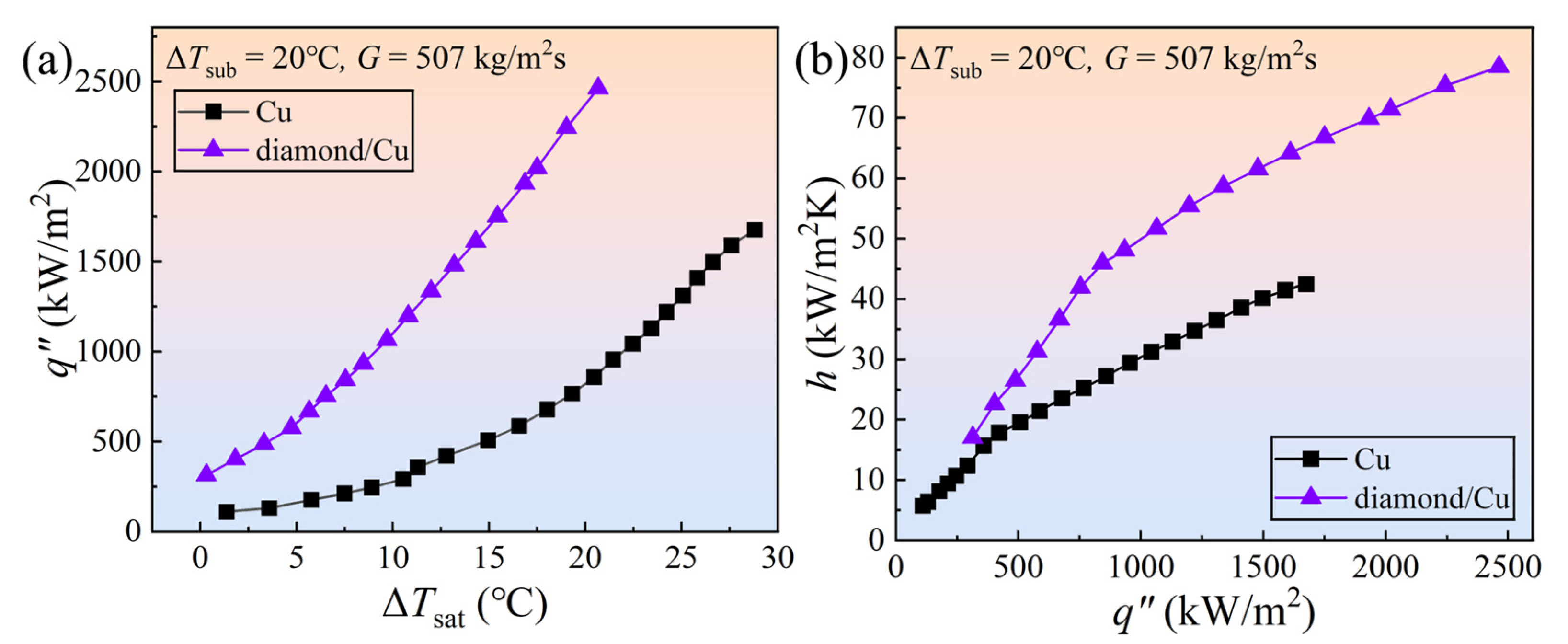
  • At the same high temperature, the diamond/Cu heat sink exhibits higher boiling intensity and an improved heat transfer coefficient h of 38–51% compared to the Cu heat sink. At a high heat flux (q″) of approximately 1600 kW/m2, the diamond/Cu heat sink has a temperature difference that is 29% lower than that of the Cu heat sink. Moreover, the diamond/Cu heat sink demonstrates a temperature fluctuation amplitude (σ) reduction of 39% compared with the Cu heat sink.
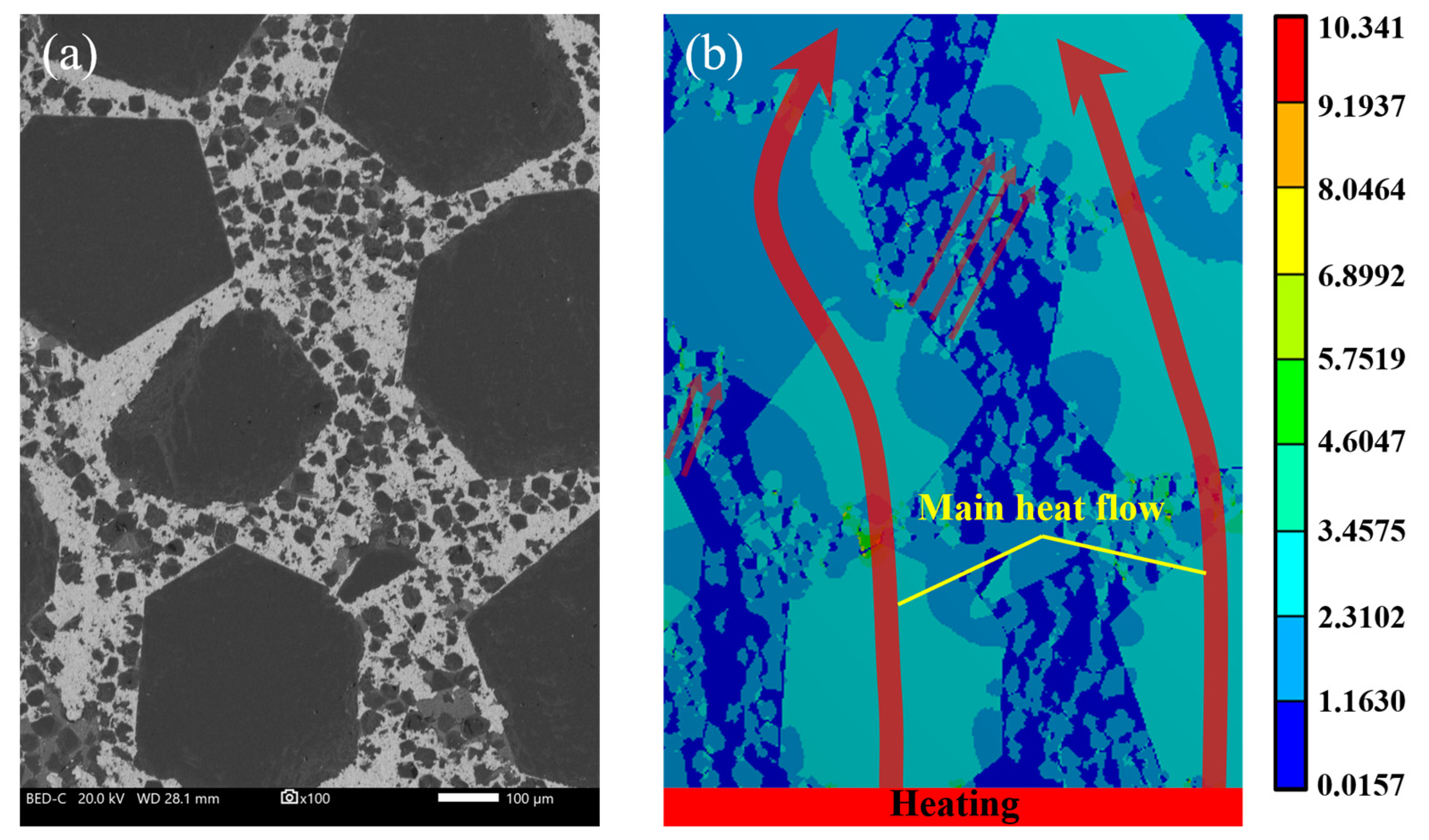
  • The heat conduction network using diamonds is the main factor enhancing the heat transfer performance of the composite. The number of active nucleation sites on the diamond/Cu surface is much greater than that on the Cu surface. The bubble departure diameter is smaller. These factors contribute to the better flow boiling heat transfer performance of the diamond/Cu heat sink.
  • The interfacial thermal conductivity between diamond and copper is crucial in studying the diamond network. The low thermal resistance of the interface significantly increases the internal heat flux of the material. Combining the transient thermal analysis model, which considers the thermal conduction network and the interfacial layer thermal conductivity, with the Fluent model allowed for a highly accurate simulation of the flow boiling heat transfer performance of the diamond/Cu composite heat sink.

Author Contributions

Conceptualization, N.W.; methodology, N.W. and M.S.; software N.W.; validation, H.G. and Z.X.; formal analysis, N.W.; investigation, N.W.; resources, M.S.; data curation N.W. and Z.X.; writing—original draft preparation, N.W.; writing—review and editing, M.S.; visualization, Z.X. and S.D.; supervision, M.S.; project administration, M.S.; funding acquisition, M.S. All authors have read and agreed to the published version of the manuscript.

Funding

This research was funded by the Youth Fund Project (No. 12396) and Youth Talent Nurturing Project (No. 5232206) of GRINM.

Institutional Review Board Statement

Not applicable.

Informed Consent Statement

Not applicable.

Data Availability Statement

The raw data cannot be shared at this time as the data are also part of an ongoing study.

Acknowledgments

We acknowledge the support of the Youth Fund Project and Youth Talent Nurturing Project of GRINM and the State Key Laboratory of Nonferrous Metals and Processes.

Conflicts of Interest

The authors declare no conflict of interest. The funders had no role in the design of the study; in the collection, analyses, or interpretation of data; in the writing of the manuscript, or in the decision to publish the results.

References

  1. Kang, J.S.; Li, M.; Wu, H.; Nguyen, H.; Hu, Y. Experimental observation of high thermal conductivity in boron arsenide. Science 2018, 361, 575–578. [Google Scholar] [CrossRef]
  2. Ghani, I.A.; Kamaruzaman, N.; Sidik, N. Heat transfer augmentation in a microchannel heat sink with sinusoidal cavities and rectangular ribs. Int. J. Heat Mass Transf. 2017, 108, 1969–1981. [Google Scholar] [CrossRef]
  3. Lee, E.; Menumerov, E.; Hughes, R.A.; Neretina, S.; Luo, T.F. Low-cost nanostructures from nanoparticle-assisted large-scale lithography significantly enhance thermal energy transport across solid interfaces. ACS Appl. Mater. Interfaces 2018, 10, 34690–34698. [Google Scholar] [CrossRef] [PubMed]
  4. Mallik, S.; Ekere, N.; Best, C.; Bhatti, R. Investigation of thermal management materials for automotive electronic control units. Appl. Therm. Eng. 2011, 31, 355–362. [Google Scholar] [CrossRef]
  5. Moore, A.L.; Shi, L. Emerging challenges and materials for thermal management of electronics. Mater. Today 2014, 17, 163–174. [Google Scholar] [CrossRef]
  6. Kuddusi, L.; Denton, J.C. Analytical solution for heat conduction problem in composite slab and its implementation in constructal solution for cooling of electronics. Energy Convers. Manag. 2007, 48, 1089–1105. [Google Scholar] [CrossRef]
  7. Siddiqui, F.R.; Tso, C.-Y.; Qiu, H.; Chao, C.Y.H.; Fu, S.C. Hybrid nanofluid spray cooling performance and its residue surface effects: Toward thermal management of high heat flux devices. Appl. Therm. Eng. 2022, 211, 118454. [Google Scholar] [CrossRef]
  8. He, L.; Tang, X.; Luo, Q.; Liao, Y.; Luo, X.; Liu, J.; Ma, L.; Dong, D.; Gan, Y.; Li, Y. Structure optimization of a heat pipe-cooling battery thermal management system based on fuzzy grey relational analysis. Int. J. Heat Mass Transf. 2022, 182, 121924. [Google Scholar] [CrossRef]
  9. Deng, D.; Zeng, L.; Sun, W.; Pi, G.; Yang, Y. Experimental study of flow boiling performance of open-ring pin fin microchannels. Int. J. Heat Mass Transf. 2021, 167, 120829. [Google Scholar] [CrossRef]
  10. Molina, J.M.; Narciso, J.; Weber, L.; Mortensen, A.; Louis, E. Thermal conductivity of Al-SiC composites with monomodal and bimodal particle size distribution. Mater. Sci. Eng. A 2008, 480, 483–488. [Google Scholar] [CrossRef]
  11. Chen, P.; Luo, G.; Shen, Q.; Li, M.; Zhang, L. Thermal and electrical properties of W–Cu composite produced by activated sintering. Mater. Des. 2013, 46, 101–105. [Google Scholar] [CrossRef]
  12. Khanna, S.; Cluskey, P.M.; Cohen, A.B.; Yang, B.; Ohadi, M. Thin thermally efficient ICECool defense semiconductor power amplifiers. J. Microelectron. Electron. Packag. 2017, 14, 77–93. [Google Scholar] [CrossRef]
  13. Erp, R.V.; Soleimanzadeh, R.; Nela, L.; Kampitsis, G.; Matioli, E. Co-designing electronics with microfluidics for more sustainable cooling. Nature 2020, 585, 211–216. [Google Scholar] [CrossRef] [PubMed]
  14. Mohammed, H.A.; Gunnasegaran, P.; Shuaib, N.H. The impact of various nanofluid types on triangular microchannels heat sink cooling performance. Int. Commun. Heat Mass Transf. 2011, 38, 767–773. [Google Scholar] [CrossRef]
  15. Deng, D.; Zeng, L.; Sun, W. A review on flow boiling enhancement and fabrication of enhanced microchannels of microchannel heat sinks. Int. J. Heat Mass Transf. 2021, 175, 121332. [Google Scholar] [CrossRef]
  16. Wang, G.; Hao, L.; Cheng, P. An experimental and numerical study of forced convection in a microchannel with negligible axial heat conduction. Int. J. Heat Mass Transf. 2009, 52, 1070–1074. [Google Scholar] [CrossRef]
  17. Deng, D.; Chen, L.; Wan, W.; Fu, T.; Huang, X. Flow boiling performance in pin fin-interconnected reentrant microchannels heat sink in different operational conditions. Appl. Therm. Eng. 2019, 150, 1260–1272. [Google Scholar] [CrossRef]
  18. Qian, J.; Li, X.; Wu, Z.; Jin, Z.-J.; Sunden, B. A comprehensive review on liquid–liquid two-phase flow in microchannel: Flow pattern and mass transfer. Microfluid. Nanofluid. 2019, 23, 116. [Google Scholar] [CrossRef]
  19. McHale, J.P.; Garimella, S.V. Heat transfer in trapezoidal microchannels of various aspect ratios. Int. J. Heat Mass Transf. 2010, 53, 365–375. [Google Scholar] [CrossRef]
  20. Kandlikar, S.G.; Widger, T.; Kalani, A.; Mejia, V. Enhanced flow boiling over open microchannels with uniform and tapered gap manifolds. J. Heat Transf. 2013, 135, 061401. [Google Scholar] [CrossRef]
  21. Cheng, X.; Wu, H. Improved flow boiling performance in high-aspect-ratio interconnected microchannels. Int. J. Heat Mass Transf. 2021, 165, 120627. [Google Scholar] [CrossRef]
  22. Yin, L.; Jiang, P.; Xu, R.; Wang, W.; Jia, L. Visualization of flow patterns and bubble behavior during flow boiling in open microchannels. Int. Commun. Heat Mass Transf. 2017, 85, 131–138. [Google Scholar] [CrossRef]
  23. Gilmore, N.; Timchenko, V.; Menictas, C. Open manifold microchannel heat sink for high heat flux electronic cooling with a reduced pressure drop. Int. J. Heat Mass Transf. 2020, 163, 120395. [Google Scholar] [CrossRef]
  24. Yin, L.; Jiang, P.; Xu, R.; Hu, H.; Jia, L. Heat transfer and pressure drop characteristics of water flow boiling in open microchannels. Int. J. Heat Mass Transf. 2019, 137, 204–215. [Google Scholar] [CrossRef]
  25. Özdemir, M.R.; Mahmoud, M.M.; Karayiannis, T.G. Flow boiling of water in a rectangular metallic microchannel. Heat Transf. Eng. 2021, 42, 492–516. [Google Scholar] [CrossRef]
  26. Qi, Z.; Zheng, Y.; Zhu, X.; Wei, J.; Liu, J.; Chen, L.; Li, C. An ultra-thick all-diamond microchannel heat sink for single-phase heat transmission efficiency enhancement. Vacuum 2020, 177, 109377. [Google Scholar] [CrossRef]
  27. Yang, Q.; Zhao, J.; Huang, Y.; Zhu, X.; Fu, W.; Li, C.; Miao, J. A diamond made microchannel heat sink for high-density heat flux dissipation. Appl. Therm. Eng. 2019, 158, 113804. [Google Scholar] [CrossRef]
  28. Qi, X.; Zhang, L.; Ren, S. Review of metal matrix composites with high thermal conductivity for thermal management application. Prog. Nat. Sci. Mater. Int. 2011, 21, 189–197. [Google Scholar] [CrossRef]
  29. Xie, Z.; Guo, H.; Zhang, X.; Huang, S. Enhancing thermal conductivity of Diamond/Cu composites by regulating distribution of bimodal diamond particles. Diam. Relat. Mater. 2019, 100, 107564. [Google Scholar] [CrossRef]
  30. Xie, Z.; Guo, H.; Zhang, X.; Huang, S.; Mi, X. Tailoring the thermal and mechanical properties of diamond/Cu composites by interface regulation of Cr alloying. Diam. Relat. Mater. 2021, 114, 108309. [Google Scholar] [CrossRef]
  31. Yuan, M.; Tan, Z.; Fan, G.; Xiong, D.; Guo, Q.; Guo, Q.; Li, Z.; Zhang, D. Theoretical modelling for interface design and thermal conductivity prediction in diamond/Cu composites. Diam. Relat. Mater. 2018, 81, 38–44. [Google Scholar] [CrossRef]
  32. Every, A.G.; Tzou, Y.; Hasselman, D.P.H.; Raj, R. The effect of particle size on the thermal conductivity of ZnS/diamond composites. Acta Metall. Mater. 1992, 40, 123–129. [Google Scholar] [CrossRef]
  33. Molina-Jordá, J.M. Nano- and micro-/meso-scale engineered magnesium/diamond composites: Novel materials for emerging challenges in thermal management. Acta Mater. 2015, 96, 101–110. [Google Scholar] [CrossRef]
  34. Molina-Jordá, J.M. Design of composites for thermal management: Aluminum reinforced with diamond-containing bimodal particle mixtures. Compos. Part A 2015, 70, 45–51. [Google Scholar] [CrossRef]
  35. Li, Y.; Zhou, H.; Wu, C.; Yin, Z.; Liu, C.; Huang, Y.; Liu, J.; Shi, Z. The Interface and fabrication process of diamond/Cu composites with nanocoated diamond for heat sink applications. Metals 2021, 11, 196. [Google Scholar] [CrossRef]
  36. Gupta, S.K.; Misra, R.D. Experimental study of pool boiling heat transfer on copper surfaces with Cu-Al2O3 nanocomposite coatings. Int. Commun. Heat Mass Transf. 2018, 97, 47–55. [Google Scholar] [CrossRef]
  37. Buchling, P.; Kandlikar, S.G. Enhanced flow boiling of ethanol in open microchannels with tapered manifolds in a gravity-driven flow. J. Heat Transf. 2016, 138, 031503. [Google Scholar] [CrossRef]
  38. Weibel, J.A.; Garimella, S.V.; North, M.T. Characterization of evaporation and boiling from sintered powder wicks fed by capillary action. Int. J. Heat Mass Transf. 2010, 53, 4204–4215. [Google Scholar] [CrossRef]
  39. Deng, D.; Tang, Y.; Liang, D.; He, H.; Yang, S. Flow boiling characteristics in porous heat sink with reentrant microchannels. Int. J. Heat Mass Transf. 2014, 70, 463–477. [Google Scholar] [CrossRef]
  40. Yin, L.; Sun, M.; Jiang, P.; Dang, C.; Jia, L. Heat transfer coefficient and pressure drop of water flow boiling in porous open microchannels heat sink. Appl. Therm. Eng. 2023, 218, 119361. [Google Scholar] [CrossRef]
  41. Law, M.; Lee, P.S.; Balasubramanian, K. Experimental investigation of flow boiling heat transfer in novel oblique-finned microchannels. Int. J. Heat Mass Transf. 2014, 76, 419–431. [Google Scholar] [CrossRef]
  42. Moffat, R.J. Describing the uncertainties in experimental results. Exp. Therm Fluid. Sci. 1988, 1, 3–17. [Google Scholar] [CrossRef]
  43. Liu, X.; Sun, F.; Wang, L.; Wu, Z.; Wang, X.; Wang, J.; Kim, M.J.; Zhang, H. The role of Cr interlayer in determining interfacial thermal conductance between Cu and diamond. Appl. Surf. Sci. 2020, 515, 146046. [Google Scholar] [CrossRef]
  44. Monje, I.E.; Louis, E.; Molina, J.M. Role of Al4C3 on the stability of the thermal conductivity of Al/diamond composites subjected to constant or oscillating temperature in a humid environment. J. Mater. Sci. 2016, 51, 8027–8036. [Google Scholar] [CrossRef]
  45. Majumdar, A.; Reddy, P. Role of electron–phonon coupling in thermal conductance of metal–nonmetal interfaces. App. Phys. Lett. 2004, 84, 4768–4770. [Google Scholar] [CrossRef]
  46. Tan, Z.; Li, Z.; Xiong, D.; Fan, G.; Ji, G.; Zhang, D. A predictive model for interfacial thermal conductance in surface metallized diamond aluminum matrix composites. Mater. Des. 2014, 55, 257–262. [Google Scholar] [CrossRef]
  47. Hopkins, P.E.; Kassebaum, J.L.; Norris, P.M. Effects of electron scattering at metal-nonmetal interfaces on electron-phonon equilibration in gold films. J. App. Phys. 2009, 105, 023710. [Google Scholar] [CrossRef]
Figure 1. Schematic of the flow loop.
Energies 16 07228 g001
Figure 2. Schematic of the test section.
Energies 16 07228 g002
Figure 3. Heat sink of diamond/Cu composites and its surface image.
Energies 16 07228 g003
Figure 4. Heat transfer performance comparison between diamond/Cu and Cu heat sinks: (a) boiling curves; (b) heat transfer coefficient curves.
Energies 16 07228 g004
Figure 5. (a) Heat sink bottom temperature distribution along the direction of fluid flow at different heat fluxes; (b) temperature-time curve of the uppermost thermocouples at various positions on the heat sinks under high heat flux (q″ = 1610.75 kW/m2).
Energies 16 07228 g005
Figure 6. Heat sink bottom temperature difference and overall temperature fluctuation amplitude σ diagram.
Energies 16 07228 g006
Figure 7. Schematic of the diamond heat conduction network and microscale interface.
Energies 16 07228 g007
Figure 8. Bubble characteristics of heat-exchange walls under same heat flux (q″ = 667.67 kW/m2): (a) diamond/Cu; (b) Cu; (c) active nucleation site density and bubble departure diameter of diamond/Cu and Cu heat sinks.
Energies 16 07228 g008
Figure 9. CFD simulation of heat transfer performance for diamond/Cu and Cu heat sinks.
Energies 16 07228 g009
Figure 10. Microstructure of the interfaces: (a) Transmission electron image of the layer between Cu and diamond; (b,c) high-resolution transmission electron micrograph; (d) schematic of heat transfer paths in the diamond/Cu.
Energies 16 07228 g010
Figure 11. (a) Cross-sectional image of the diamond/Cu composite; (b) simulation of stationary heat flux based on transient thermal analysis.
Energies 16 07228 g011
Figure 12. Refinement of heat transfer model: (a) input interfacial thermal conductivity coefficients; (b) boiling curves; (c) heat transfer coefficient curves.
Energies 16 07228 g012
Table 1. The uncertainties of the measured and calculated parameters.
ParametersMaximum Relative Uncertainty
T (T-type)±0.30 °C
T (K-type)±0.20 °C
G±2.50%
U±0.50%
I±0.50%
q“±1.78%
h±1.57%
Table 2. Material parameters for the calculation of interface thermal conductivity by DMM.
MaterialDensity
ρ (kg/m3)
Thermal Conductivity
λ (W/mK)
Specific Heat
c (J/kgK)
Phonon Velocity
ν (m/s)
Cu89003983862881
Cr3C26680194565628
Diamond3520150051212,775
Table 3. Interfacial thermal conductivity coefficients calculated by DMM.
InterfaceCu-Cr3C2Cr3C2-DiamondDiamond-Cr3C2Cr3C2-Cu
hIF (W/m2K)5.138 × 1086.966 × 1084.820 × 1091.955 × 109
Disclaimer/Publisher’s Note: The statements, opinions and data contained in all publications are solely those of the individual author(s) and contributor(s) and not of MDPI and/or the editor(s). MDPI and/or the editor(s) disclaim responsibility for any injury to people or property resulting from any ideas, methods, instructions or products referred to in the content.

