1. Introduction
The doubly fed induction generator (DFIG) is a popular choice for wind power generation. With the increasing penetration of wind power, the DFIG is required to be capable of participating in the frequency regulation of the power system [
1]. In addition to the frequency regulation provided by the traditional synchronous generator (SG), the DFIG may help to improve the frequency stability of the power system through the virtual inertia control [
2,
3], the droop control [
4], or the combination of the aforementioned two control schemes [
5].
Energy storage has proven to be another efficient method to enhance the frequency stability of the power system [
6,
7]. Among the various types of energy storage systems, supercapacitor energy storage (SES) has the merits of large power density and instant high active power output [
8,
9,
10], making it a favored option for the primary frequency regulation of the power system.
To further improve the frequency regulation capability of the DFIG, the SES may be implemented in the DC capacitor of the DFIG [
11,
12]. The improved frequency regulation capability with the combination of the DFIG and the SES (DFIG-SES) has been verified in [
13].
To verify the enhanced frequency regulation capability of the DFIG-SES, a time-domain simulation of the frequency response under the load disturbance provides accurate results [
14]. However, a detailed model of all the equipment within the power system is needed to carry out the time-domain simulation, making it relatively difficult and complex to realize for the power system operators. In view of this, the dynamic power flow (DPF) analysis may be adopted [
15,
16,
17], which simplifies the power system model by retaining only the key factors that affect the frequency response [
18,
19]. With the DPF, the system frequency is calculated on a simplified model basis, yet with satisfactory accuracy. The dynamic change in the system power flow during the frequency regulation is also obtained.
The scheme to provide frequency regulation capability with the DFIG-SES system is supported by the existing research. The applicability of the DPF analysis to evaluate the frequency regulation performance has also been verified. However, when applying the DPF analysis to the scenario of the DFIG-SES system participating in the frequency regulation, there are still some issues to be addressed, as listed below:
- (i)
With the traditional DPF analysis, the power flow is solved with generators being treated as PQ nodes, which means that the internal equipment and power flow of the generators are ignored [
20]. The simplifications adopted by the traditional DPF analysis need to be adjusted when applied to the frequency regulation analysis of the DFIG-SES system. On the one hand, both the DFIG and the SES are capable of providing active power response much faster than the SG [
21]; thus, the delay in the active power response of the SG caused by the governor system needs to be taken into consideration [
22]. On the other hand, the SES is connected to the DC-link capacitor of the DFIG; thus, the active power output of the SES is involved with the internal power flow of the DFIG [
23]. In view of this, a detailed model of the internal power flow of the DFIG needs to be introduced to the DPF analysis.
- (ii)
With the SES participating in the frequency regulation, its control strategy, as well as the operation constraints, need to be incorporated into the framework of the DPF analysis. Unlike the generation units such as the SG or the DFIG, the capability of the SES to continuously provide active power output is constrained by its stored energy; thus, the state of charge (SOC) constraint needs to be included in the DPF analysis [
24].
- (iii)
Although the SES is capable of providing instant active power response to the frequency deviation, its capacity is still comparatively small compared to the DFIG. Thus, the DFIG needs to fully utilize its active power reserve to support the system frequency so as to avoid large active power output of the SES, which results in the over-discharging operation condition that reduces the life cycle of the SES. Schemes like the variable droop may be adopted [
25] and incorporated into the DPF analysis to verify the improvement in the operation condition of the SES.
Motivated to address the above issues, this paper establishes the DPF model that is capable of properly assessing the frequency regulation capability of the DFIG-SES system. To improve the model accuracy, the internal power flow of the DFIG-SES system and the governor delay of the SG are modeled in the DPF analysis. Based on the DPF model, analysis results of the operation parameters of the DFIG-SES system and the SG during the frequency regulation are obtained. The improved frequency regulation performance of the DFIG-SES system is also supported by the DPF analysis results. Numerical analysis based on the modified IEEE 14-bus system is carried out to verify the feasibility and effectiveness of the DFIG-SES scheme to participate in the frequency regulation.
This paper is organized as follows. In
Section 2, the configuration of the DFIG-SES system and the control strategies of the DFIG and the SES to participate in the frequency regulation are introduced. In
Section 3, the algorithm to carry out the DPF analysis on the frequency regulation performance with the joint participation of the SG and the DFIG is explained. Extending from
Section 3, the method to incorporate the SES in the DPF analysis is presented in
Section 4 so as to assess the overall frequency regulation capability of the DFIG-SES system. The adopted variable droop control scheme applied to the DFIG is also presented. The numerical analysis based on a modified IEEE 14-bus test system is carried out in
Section 5, and the yielded conclusions are given in
Section 6.
2. Frequency Regulation by DFIG-SES with Deloaded Operation and Droop Control
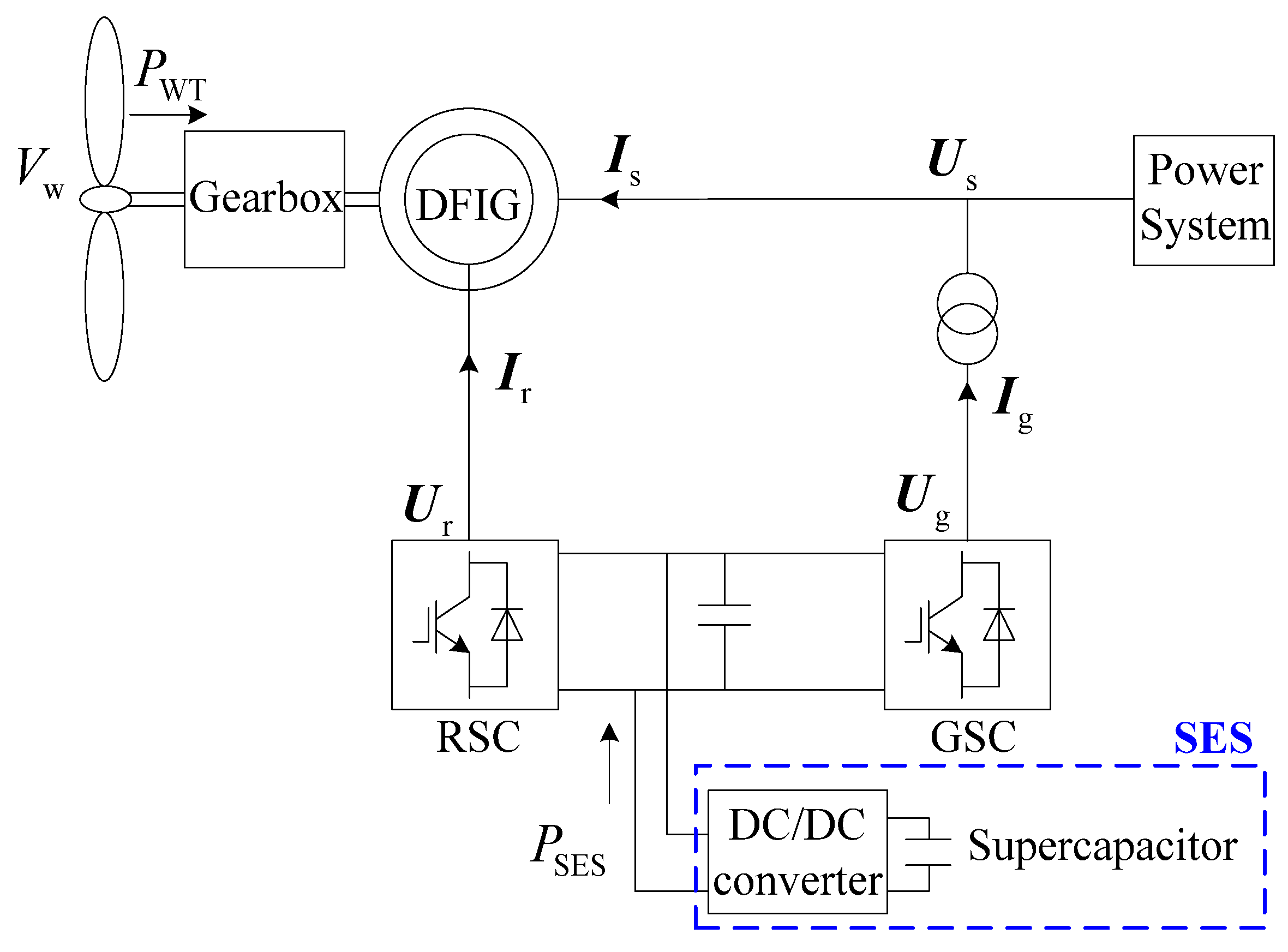
The configuration of the DFIG-SES system is shown in
Figure 1, where
U and
I are the voltage and current,
Vw is the wind speed,
PWT is the mechanical power captured by the wind turbine (WT), and
PSES is the active power output of the SES. Subscripts s, r, and g denote the stator, the rotor-side converter (RSC), and the grid-side converter (GSC), respectively. As shown in
Figure 1, the SES is connected to the DC-link capacitor of the DFIG through the DC/DC converter, which is capable of providing active power response at the time scale of milliseconds in order to meet the frequency regulation demands of the DFIG.
2.1. Deloaded Operation of DFIG to Reserve Active Power for Frequency Regulation
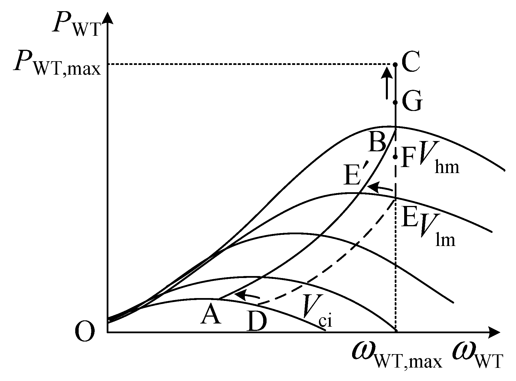
To participate in the frequency regulation of the power system, the DFIG needs to operate under the deloaded mode for the active power reserve. Through overspeed control or pitch angle regulation, the mechanical power captured by the DFIG may be reduced. In this case, the operation point of the DFIG moves away from the maximum power point (MPP) and switches to the deloaded operation mode. The deloaded operation curve of the DFIG under different wind speeds is shown in
Figure 2, where
and
are the maximum values of the captured mechanical power and the rotating speed of the WT, respectively,
Vci corresponds to the cut-in wind speed,
Vlm and
Vhm are critical points that divide the whole wind speed range into the low wind speed section (
Vw <
Vlm), the medium wind speed section (
Vlm ≤
Vw <
Vhm), and the high wind speed section (
Vhm ≤
Vw). The ABC curve in
Figure 2 corresponds to the maximum power point tracking (MPPT) operation mode, while the DEFG curve corresponds to the deloaded operation mode of the DFIG.
With the active power reserve, the DFIG is capable of participating in frequency regulation through droop control. In response to the system frequency deviation, the captured mechanical power by the WT is adjusted according to (1), where
PWT,del is the captured mechanical power under the deloaded mode,
kdel is the deloading percentage,
PWT,MPPT is the optimal value of the captured mechanical power under the MPPT operation mode,
is the frequency deviation, and
KDFIG is the droop coefficient of the DFIG.
2.2. Frequency Regulation by SES Implemented to DFIG
The active power of the SES may be adjusted in its charging and discharging process. Within the constraint of the SOC, the SES adjusts its output active power to respond to the frequency deviation based on the droop control, as the DFIG does, which is quantified by (2), where
KSES is the droop coefficient of the SES [
26].
Considering the constraint of the SOC, the maximum energy that can be released from the SES is quantified by (3). When the maximum value is reached during the frequency regulation, the SES is switched out from the DFIG-SES system and no longer participates in the frequency regulation.
where
Wmax is the maximum energy that is releasable from the SES,
CSES is the capacitance of the SES,
Umin and
Uini are the minimum allowable voltage and the initial voltage of the SES, respectively, and
tini and
tend are the initial and ending instants of the frequency regulation process with the participation of the SES.
3. DPF Analysis Considering Governor Delay and DFIG Inertia
To evaluate the frequency regulation performance, the DPF analysis is carried out. Compared with the static power flow analysis that treats the system frequency as a constant value, the DPF is capable of further evaluating the dynamics of the system frequency under the active power imbalance.
3.1. Traditional DPF Model
The DPF model assumes that the frequency at different locations of the power system is consistent, and its value is determined based on the average system frequency model. The active power imbalance is regarded as the accelerating power in the DPF analysis, whose impact on the system frequency is determined by the total inertia of the generators, as shown in (4).
where
is the sum of the inertia time constants of the generators,
is the accelerating power,
and
are the sums of the active power generation and load, respectively, and
is the active power loss of the power system.
To solve the dynamic power flow, the accelerating power is allocated to different generation units based on their inertia time constants, which are treated as additional active power loads at the connection nodes of the generation units. In addition, the active power output of the generation units and the loads in the power flow model are modified based on their response to the frequency deviation. The modified equation of the power balance at node
i is given by (5), where
and
denote the active power and reactive power imbalance,
and
are the active and reactive power output of the generator at node
i,
and
are the active power load and reactive power load at node
i,
and
are the coefficients describing the frequency characteristics of the generator and the active power load at node
i, respectively, and
is the inertia time constant of the generator connected to node
i.
When carrying out the DPF analysis, firstly, the system frequency change resulting from the accelerating power is calculated based on (4). Then, the power flow equations are modified according to (5) to obtain the updated power flow results, based on which the accelerating power is recalculated and once again applied to the system frequency calculation based on (4). The alternative calculation of the system frequency and power flow ends when the accelerating power finally converges to zero, i.e., the active power generation and load imbalance are eliminated by the frequency regulation. In this case, the steady-state values of the post-disturbance power flow and system frequency are obtained.
3.2. Quantification of Generator Inertia
As can be seen from (5), the inertia of the generators needs to be quantified for the DPF analysis. For the DFIG-integrated wind power system, both the inertia of the traditional SG and the DFIG need to be taken into consideration. The inertia time constant of the generator is determined by the stored kinetic energy in the rotor. Normally, the inertia time constant of the SG is treated as a fixed value since its rotor is maintained at the synchronous rotating speed during operation. Meanwhile, the rotor speed of the DFIG is not directly linked to the system frequency; thus, its inertia needs to be evaluated based on the releasable kinetic energy of the DFIG rotor when participating in the frequency regulation so as to obtain the equivalent inertia time constant of the DFIG. The releasable kinetic energy of the DFIG rotor is affected by various factors, including the wind speed, the deloaded operation, and the amount of active power reserve. The calculation of the equivalent inertia time constant of the DFIG within different wind speed sections is shown below [
27].
- (1)
Low wind speed section (Vw < Vlm)
Within the low wind speed section, the DEIG adopts the overspeed control to realize the active power reserve. When the DFIG needs to increase its active power output to support the system frequency, the rotor speed can be reduced from the deloaded operation point (
) to the MPPT operation point (
), corresponding to the curve DA in
Figure 2. In this case, the maximum kinetic energy that can be released from the DFIG rotor is obtained, which is then transformed to the equivalent inertia time constant of the DFIG, considering the base power of the power system, as shown in (6).
where
HDFIG is the equivalent inertia time constant of the DFIG,
J is the rotary inertia of the DFIG rotor,
p is the pole pair number of the DFIG, and
SB is the base power of the power system.
- (2)
Medium wind speed section (Vlm ≤ Vw < Vhm)
Within the medium wind speed section, the rotor speed of the DFIG reaches its maximum value (
) under the deloaded mode; thus, the active power reserve of the DFIG is realized through both the overspeed control (rotor speed not exceeding its maximum value) and the pitch angle regulation. When the DFIG needs to release the active power reserve for the frequency regulation, the pitch angle is reduced to zero, and the rotor speed is reduced from its maximum value to the optimal rotor speed
under the MPPT mode (corresponding to curve EE’ in
Figure 2). In this case, the equivalent inertia time constant of the DFIG is given by (7).
- (3)
High wind speed section (Vhm ≤ Vw)
As the wind speed increases to Vhm, the optimal rotor speed reaches its maximum value (); thus, the overspeed control is no longer applicable for the deloaded operation. The active power reserve of the DFIG is solely realized through pitch angle regulation, and the rotor speed of the DFIG is fixed at its maximum value when releasing the active power reserve. No kinetic energy change in the DFIG rotor is involved in the frequency regulation process; thus, the equivalent inertia time constant of the DFIG is zero within the high wind speed section.
3.3. Active Power Response of SG Considering Governor Delay
In the DPF analysis, the active power adjustment of the generators in response to the frequency deviation is considered. For the SG, its active power is adjusted in the droop control form when carrying out the primary regulation. However, the control target of active power cannot be instantly reached, considering the delay of the governor system that is responsible for the primary frequency regulation. Thus, the governor delay needs to be taken into consideration for the DPF analysis.
In the traditional DPF analysis, the adjustment to the active power of the SG when performing the primary frequency regulation is given by (8).
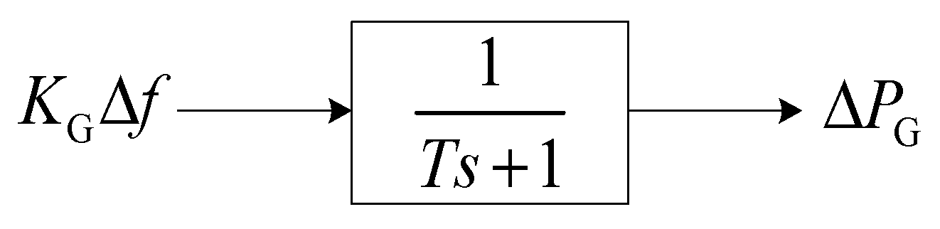
By modeling the governor delay based on a first-order inertia system [
28] (as shown in
Figure 3, where
T is the inertia time constant), the response of the governor considering its control delay is quantified based on (9), which is then incorporated to the DPF analysis to consider the governor delay.
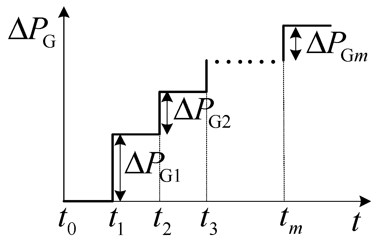
Assuming that the DPF analysis is carried out with the time step
, the system frequency is calculated at the start of each time step, and the adjustment to the active power of the SG without considering the governor delay is calculated based on (10), as illustrated by
Figure 4, where subscript
m denotes the
m-th time to calculate the system frequency, which is also the start of the
m+1-th time step of the DPF analysis.
With the governor delay of the SG taken into consideration, the actual response to the adjustment of the active power
is quantified by (11). As can be seen from (11), the adjustment of the active power is not instantly realized at the start of the time step, as
Figure 4 illustrates, but takes a certain time to reach the control target.
By combining the delayed response as given by (11), the actual response of the active power of the SG is calculated based on (12).
where
N is the total number of times to calculate the system frequency till the system frequency reaches the steady state in the DPF analysis.
Meanwhile, for the DFIG and the SES, their active power is regulated through the quick response of the converter control, making the transient process of the active power adjustment negligible for the DPF analysis.
4. DPF Analysis with DFIG-SES System Participating in Frequency Regulation
4.1. Internal Power Flow Analysis of DFIG-SES System
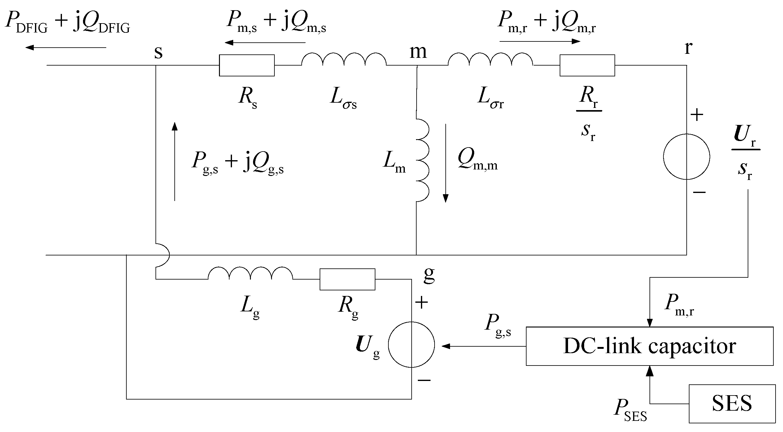
Since the SES is connected to the DC-link capacitor of the DFIG, the internal power flow of the DFIG-SES system needs to be considered in the DPF analysis. In addition, the active power output of the DFIG is not equal to the captured mechanical power by the WT due to the internal active power loss, which can only be obtained through the detailed internal power flow calculation. Based on the equivalent circuit model of the DFIG and the active power output of the SES, the internal power flow model of the DFIG-SES system is illustrated in
Figure 5, where s, r, m, and g denote the stator, the rotor, the imaginary connection point between the stator and the rotor, and the GSC, respectively,
R and
L are the resistance and inductance,
and
are the self-inductances of the stator and the rotor, respectively,
is the mutual inductance between the stator and the rotor, and
is the rotor slip. The power flow equations of the DFIG-SES system are given by (13)–(18).
Equations (13) and (14) represent the active and reactive power balance at the imaginary connection point between the stator and rotor circuits.
The reactive power outputs of the DFIG and the GSC need to be set to solve the power flow of the DFIG. Equations (15) and (16) ensure that the power flow solution adheres to the prescribed values of the reactive power outputs of the DFIG and the GSC, where the subscript ref denotes the reference value.
Equation (17) describes the torque balance between the mechanical torque of the WT and the electromagnetic torque of the DFIG, where
is the torque imbalance and
is the electromagnetic torque.
Since the SES is connected to the DC-link capacitor of the DFIG, the internal power flow of the DFIG is affected when the active power output of the SES is adjusted to participate in the frequency regulation. For the power flow analysis of the DFIG, the original active power balance between the RSC and the GSC is changed to the active power balance among the RSC, the GSC, and the SES. Equation (18) is the modified power flow equation due to the connection of the SES to the DC-link capacitor of the DFIG. With (18) in the power flow model, the impact of the power output of the SES on the internal power flow of the DFIG-SES system may be considered in the DPF analysis.
4.2. DPF Analysis of DFIG-SES System Participating in Frequency Regulation
With the equivalent inertia of the DFIG taken into consideration, the system frequency in the DPF analysis is calculated based on the dynamic frequency equation given by (19).
where
is the total inertia time constant of the DFIG-integrated power system.
When active power imbalances occur in the power system, the DPF analysis first calculates the deviation of the system frequency based on (19) and then determines the active power response of the generators.
For node
i with the connection of the SG, the adjustment to the active power output of the SG is modeled considering the governor delay analyzed in
Section 3.3. With the adjusted active and reactive power output of the SG, the power balance equation of node
i is modified to (20).
In response to the frequency deviation, the DFIG-SES system both adjusts the captured mechanical power of the WT (PWT) to release the active power reserve of the DFIG and adjusts the active power output of the SES (PSES) to release the stored energy of the SES. This will lead to a change in the internal power flow of the DFIG-SES system, which needs to be updated by solving the power flow equations given by (13)–(18).
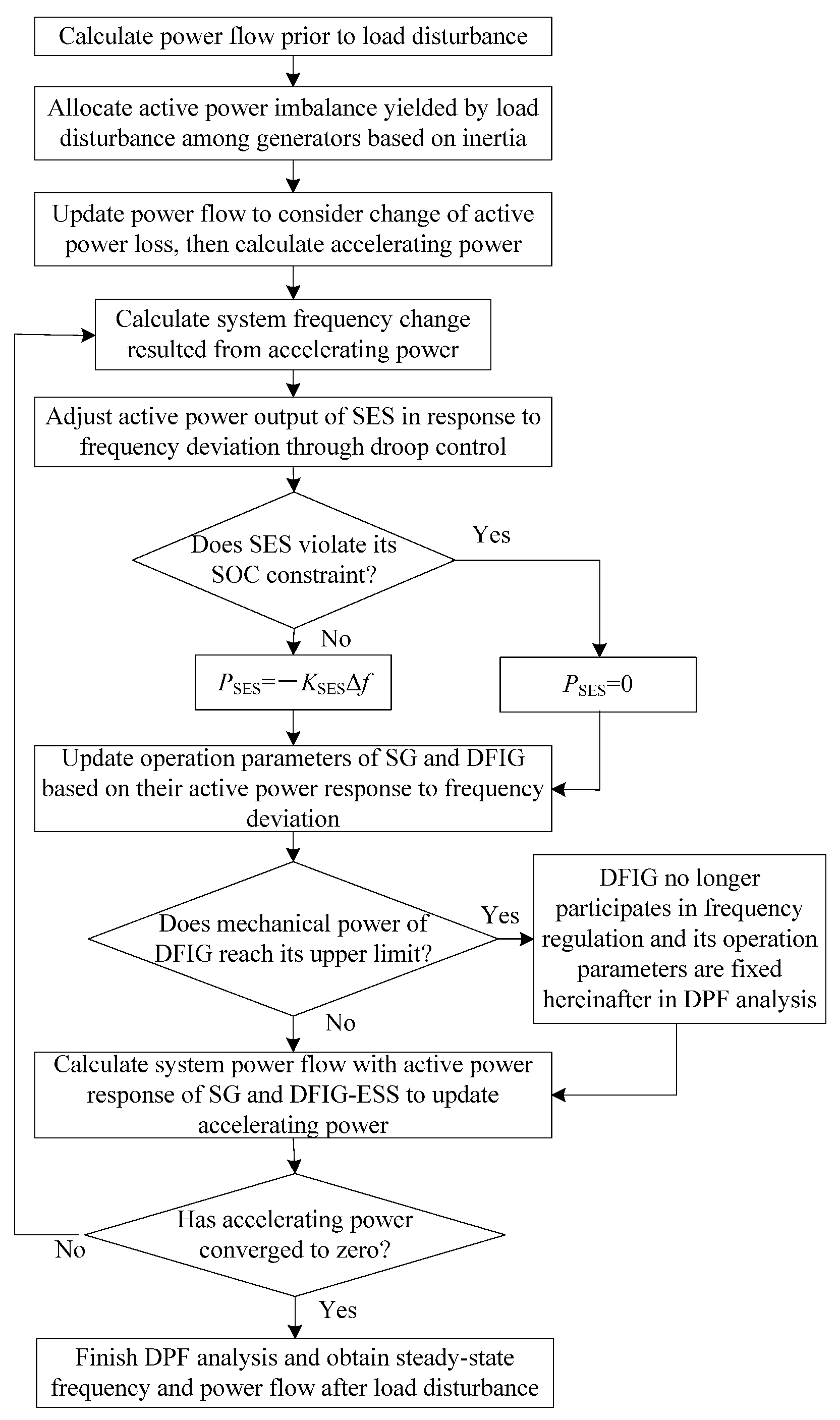
Based on the updated power flow result that considers the active power responses of the generators, the accelerating power is recalculated and once again used to analyze the system frequency. The alternative calculation of the system frequency and the power flow continues until the accelerating power converges to zero, which marks the end of the DPF analysis. The detailed procedure of the DPF analysis with the DFIG-SES system participating in the frequency regulation is shown in
Figure 6.
The constraints on the active power support capabilities of both the DFIG and the SES are considered in the DPF analysis. For the SES, once its SOC reaches the lower limit, the SES is cut off from the DFIG, and its active power output is set to zero for the remainder of the DPF analysis. Meanwhile, once the captured mechanical power of the DFIG reaches its maximum value, i.e., the DFIG returns from the deloaded mode back to the MPPT mode, the operating state of the DFIG is fixed at the MPPT mode for the remainder of the DPF analysis.
4.3. Variable Droop Coefficient of DFIG for Fully Utilization of Active Power Reserve
The increment of the active power output of the DFIG in response to the frequency deviation is affected by the setting of the droop control coefficient. With the same deloading percentage, the capacity of the active power reserve is affected by the wind speed. In order to fully utilize the active power reserve under different wind speeds, the variable droop coefficient setting scheme is adopted, aiming to elevate the frequency nadir after the load disturbance. The setting of the variable droop coefficient is given by (21).
To set the variable droop coefficient, first, a base case is selected (in the low wind speed section), and the active power reserve of the DFIG in this case, i.e., , is obtained. Based on the active power reserve and the allowable frequency deviation of the power system, the droop coefficient of the DFIG in this case, i.e., , is determined. The actual active power reserve is updated as the wind speed changes, and the corresponding droop coefficient of the DFIG is adjusted based on (21).
5. Numerical Analysis
The test system is established based on the IEEE 14-bus test system [
29]. As for the wind power integration, a wind farm including 50 DFIGs of the same type and a capacity of 2 MW is connected to node 7 of the IEEE 14-bus test system. The rated frequency of the power system is 50 Hz. The parameters of the DFIG are adopted from Ref. [
30]. The deloading percentage of the DFIG is set to
kdel = 20%. Corresponding to this deloading percentage, the critical wind speeds that determine the different wind speed sections are calculated and given by
Vlm = 8.796 m/s and
Vhm = 11.091 m/s, respectively. The maximum capacity of the stored energy in SES is set to
Wmax = 2.5 p.u. The instant load surge of 40 MW active power is applied as the load disturbance scenario.
The DPF program is written as .m files using the MATLAB software (MATLAB R2018b), which is run on a personal computer (2.50 GHz Intel Core i5-7300HQ CPU, 8.00 GB RAM) to obtain the following calculation results and figures. The self-written program applies the trapezoidal method to solve the differential equations. As for the IEEE 14-bus test system, node 1 is the slack bus, nodes 2, 3, 6, and 8 are treated as PV nodes, and the remaining nodes are treated as PQ nodes in the power flow calculation.
5.1. Impact of Governor Delay on Frequency Evaluation with DPF Analysis
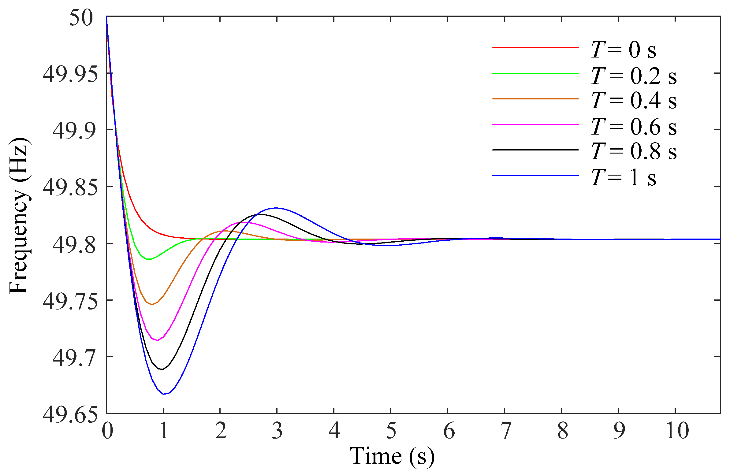
In this section, the necessity to consider the governor delay in the DPF analysis is verified. Details of the simulation scenario are given as follows. At the wind speed of 7.5 m/s, only the DFIG without the SES participates in the frequency regulation alongside the SGs. As for the DFIG, it adopts the fixed droop coefficient, i.e.,
KDFIG = 25. The calculation results of the system frequency by the DPF analysis with different inertia time constants of the governor delay are compared in
Figure 7. Since only the SG participates in the frequency regulation, the system frequency is obtained by solving the differential Equation (4) based on the trapezoidal method. With the governor delay of the SG taken into consideration, the dynamic change in its active power output during the frequency regulation is calculated based on (12).
As can be seen from
Figure 7, the impact of the governor delay is more significant at the early stage of the frequency regulation. With large inertia time constants of governor delay, the active power output of the SG may not be increased in time to compensate for the load change at the early stage of the frequency regulation, leading to the transient frequency nadir. As time goes by, the active power output of the SG gradually approaches its control target prescribed by the primary frequency regulation; thus, the calculation results of the steady-state frequency are consistent with different values of the governor delay.
Figure 7 reveals that the first of the three issues discussed in the Introduction, i.e., the simplification made to the generators in the traditional DPF analysis, does lead to the degraded accuracy of the analysis results. Moreover, the incorporation of the governor delay in the DPF analysis helps to improve the accuracy of the frequency calculation results and can reflect the transient frequency nadir of the whole frequency regulation process.
5.2. Validation to Improved Frequency Regulation Performance with DFIG-SES System
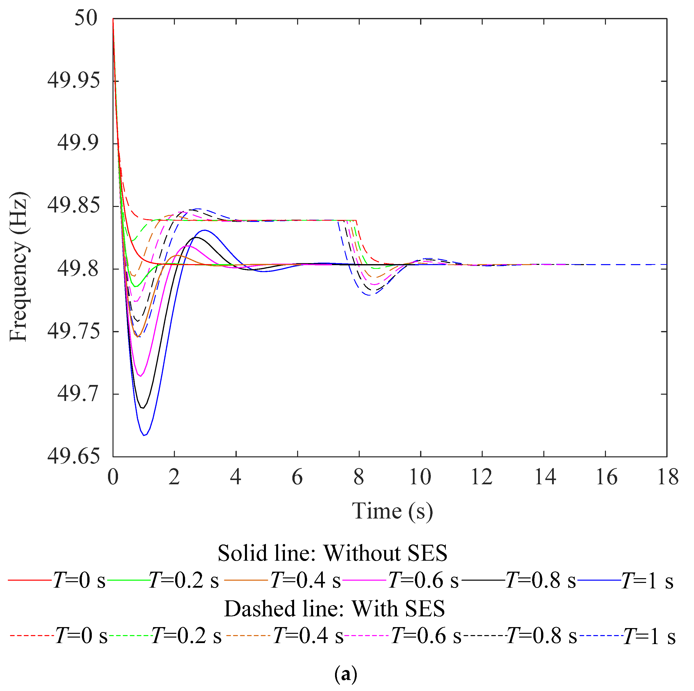
In this section, the improvement to the frequency regulation performance with the DFIG-SES system is validated based on the DPF analysis. The load disturbance scenario applied in
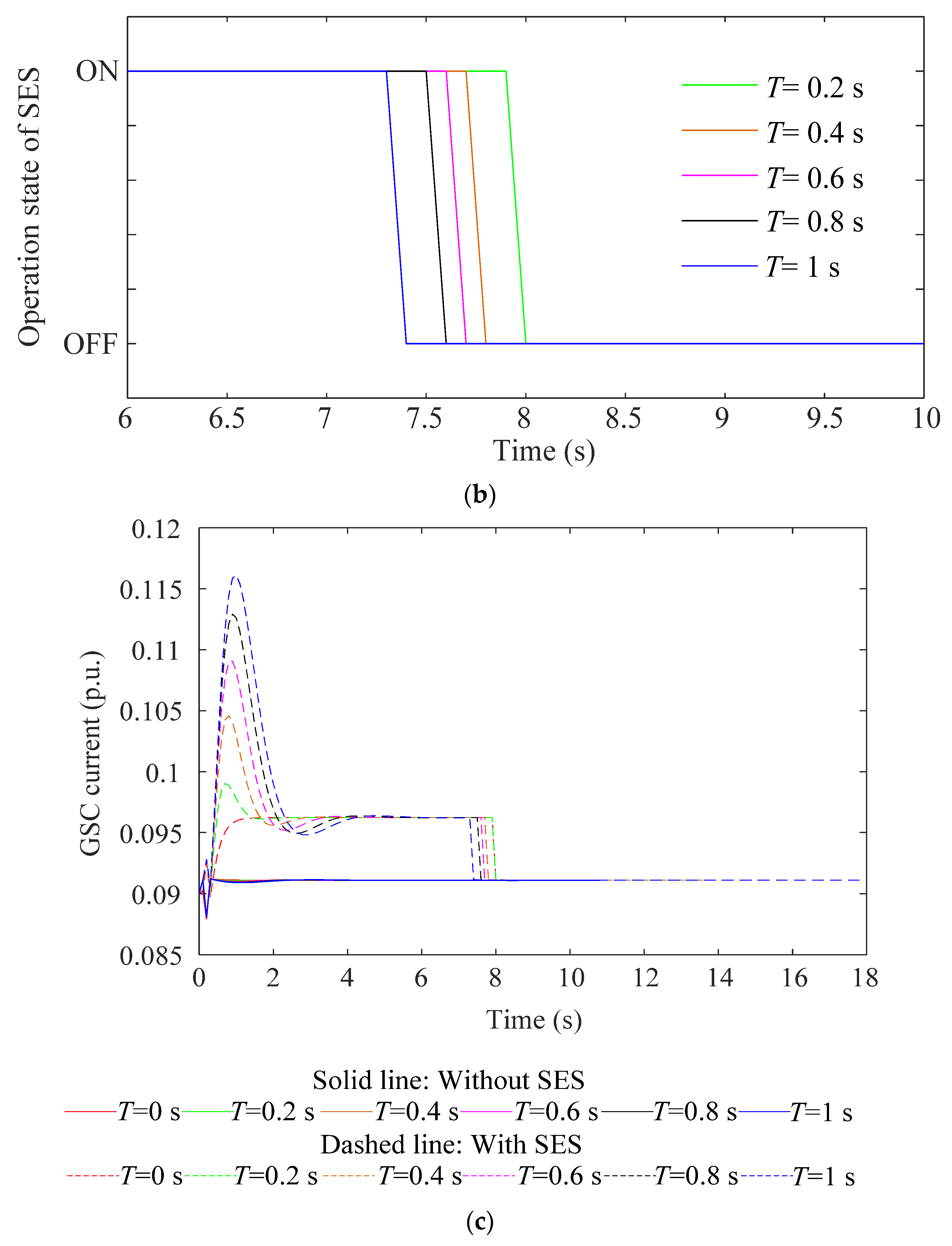
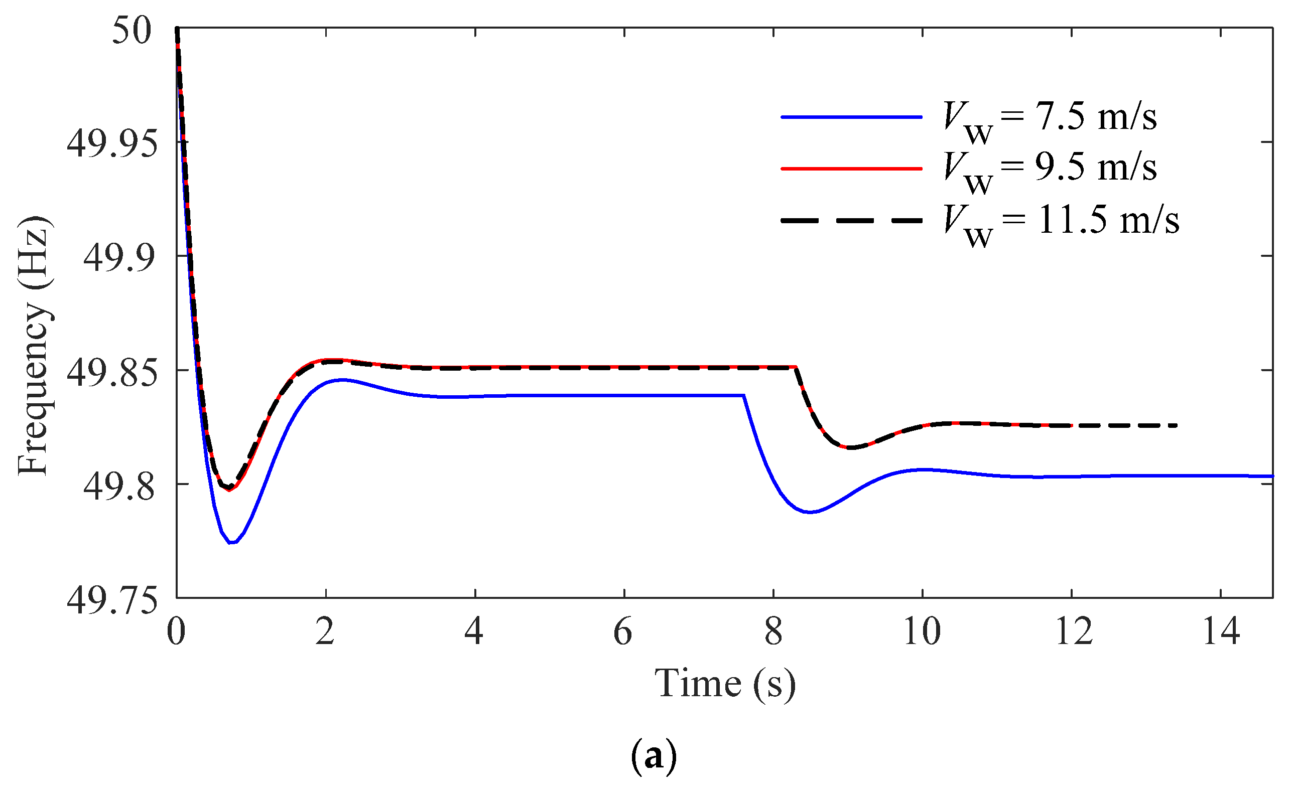
Section 5.1 is adopted here. For the DFIG-SES system, both the DFIG and the SES respond to the frequency deviation with the droop control to adjust their active power output. With the DFIG participating in the frequency regulation, the system frequency is obtained by solving the differential Equation (19) that includes the equivalent inertia of the DFIG. The internal power flow of the DFIG is solved based on Equations (13)–(18) to obtain the operation parameters of the DFIG, e.g., the GSC current during the frequency regulation. The comparison of the frequency response before and after the SES participates in frequency regulation is shown in
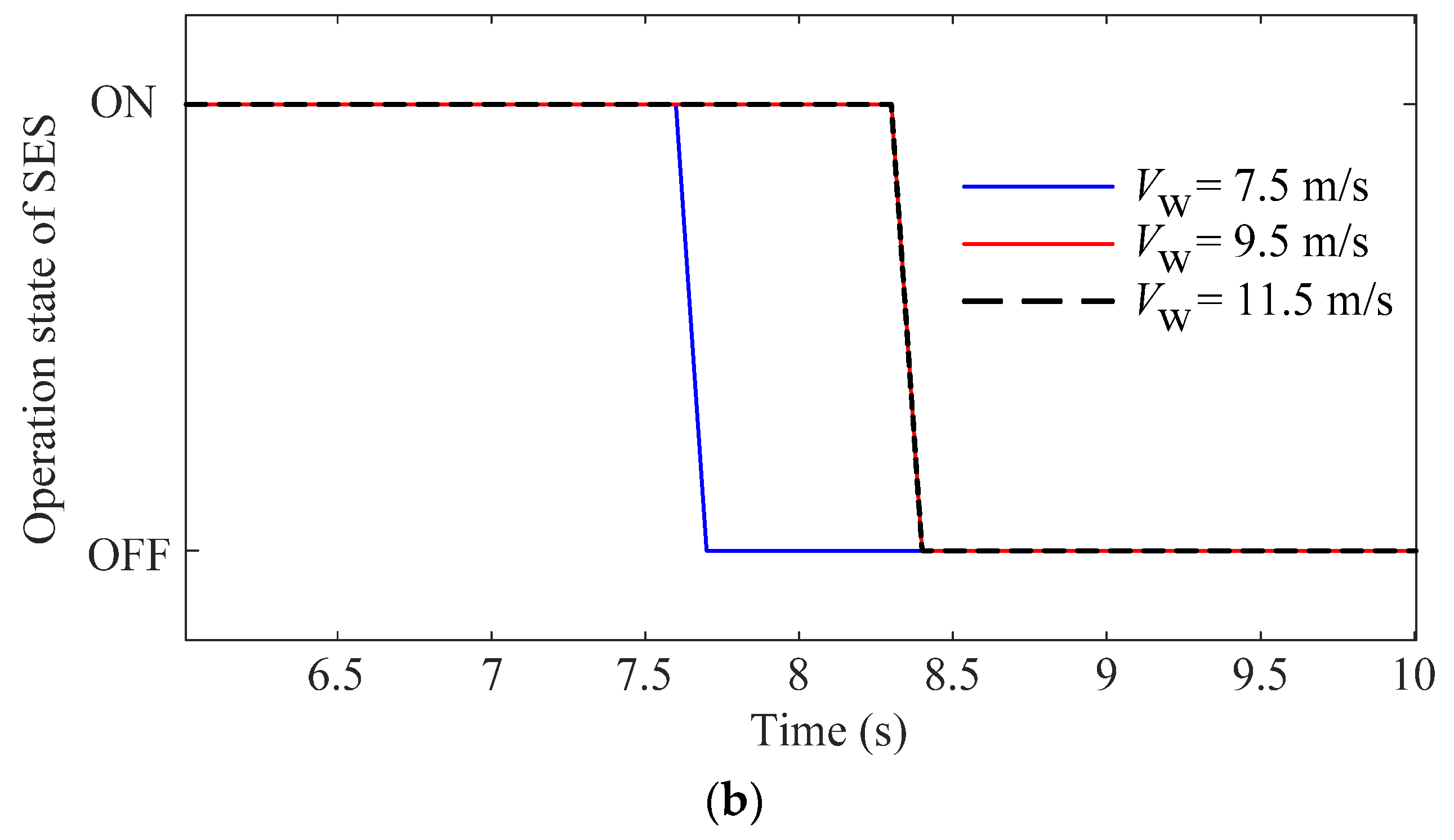
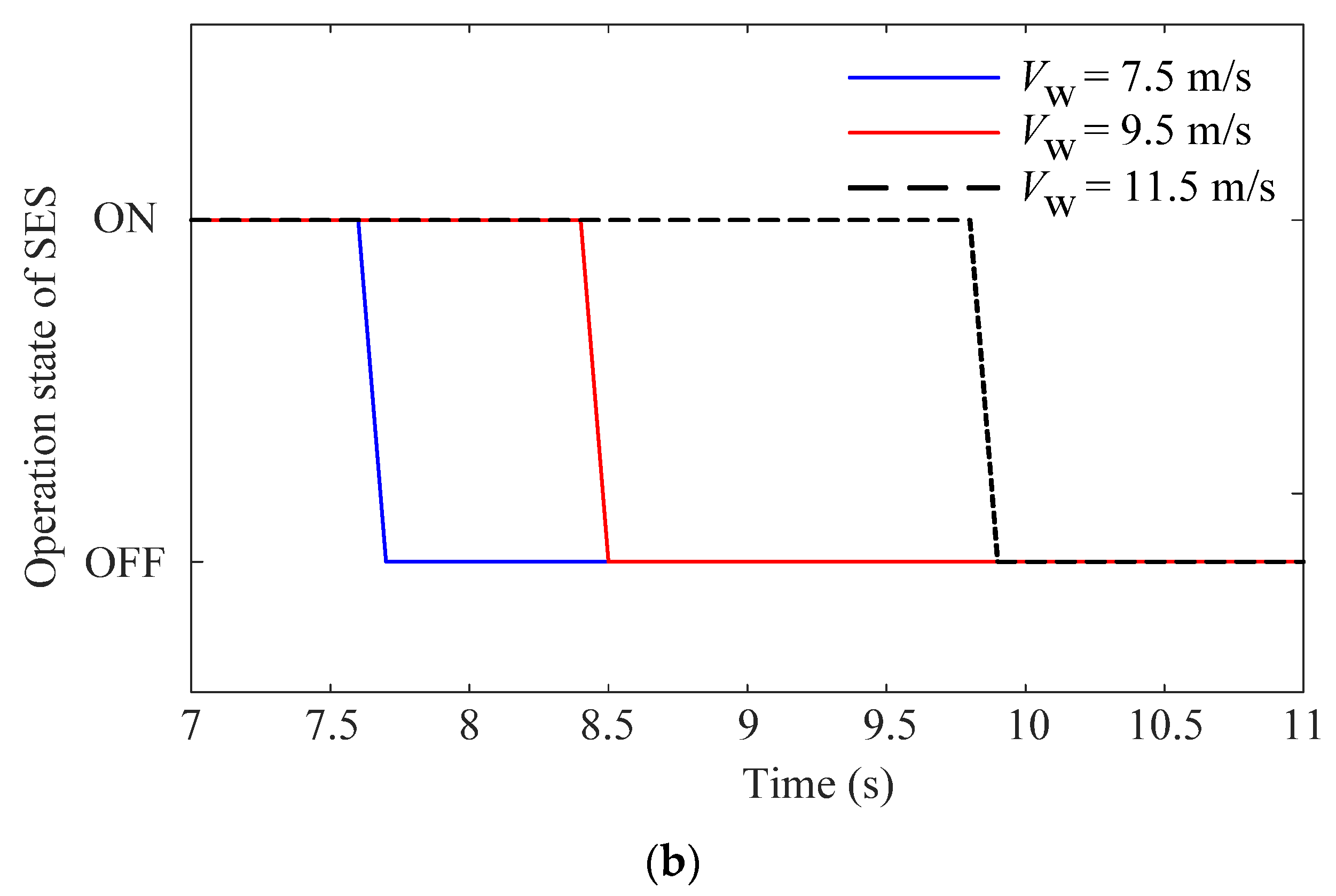
Figure 8a. Considering the limited energy storage capacity of the SES, the SES is switched out after its SOC hits the lower-boundary limit. The operation states of the SES are evaluated with the DPF analysis, and the critical moment corresponding to the switch-out of the SES is obtained, as shown in
Figure 8b. The increased active power output of the SES is transmitted to the terminal of the DFIG via the GSC. The increased GSC current is obtained from the power flow solution in the DPF analysis, as shown in
Figure 8c.
As can be seen from
Figure 8a, with the SES participating in the frequency regulation, the frequency regulation capability of the DFIG is further enhanced.
Figure 8b reveals that, as the frequency regulation process continues, the stored energy of the SES will be used up with the continuous active power output, leading to the switch-out of the SES. With the smaller inertia time constants of the governor delay, the SG may provide a faster response to the primary frequency regulation, the active power output of the SES will be reduced, and the SES switches out after a longer duration of operation, as
Figure 8b shows. Correspondingly,
Figure 8c shows the increased GSC current due to the active power output of the SES during the frequency regulation.
Figure 8a shows that the improvement to the frequency regulation performance brought by the SES is revealed not only by the increased frequency nadir but also by the increased steady-state frequency before the switch-out of the SES. The SES is switched out once it has released all of its stored energy in the frequency regulation, and at that very instant, the active power output of the SES is immediately reduced from −
KSESΔ
f to zero (judgment link on violation to the SOC constraint of the SES in
Figure 6), resulting in the active power loss and leading to the second frequency drop. Although the switch-out of the SES after releasing all its stored energy yields another active power imbalance and the second frequency drop, the maximum frequency deviation during the whole frequency regulation process is still smaller than that with only the DFIG participating in the frequency regulation.
Figure 8 reveals that the second of the three issues discussed in the Introduction, i.e., the necessity to include the operation state and the SOC constraint of the SES in the DPF analysis, does contribute to obtaining more practical analysis results of the frequency regulation performance by the DFIG-SES system.
5.3. Improved Frequency Regulation Performance with Variable Droop Coefficient of DFIG
In this section, the DPF analysis is carried out to verify the improvement to frequency regulation by the variable droop coefficient setting of the DFIG introduced in
Section 4.3. Different wind speeds are applied in this section to consider the different capacities of the active power reserve. Two schemes of the droop coefficient setting to the DFIG are adopted and compared to show the improvement.
Scheme 1: Constant droop coefficient KDFIG = 25;
Scheme 2: Variable droop coefficient setting based on (21).
With Scheme 1 and Scheme 2, the DPF analysis is separately carried out to evaluate the frequency regulation performance. The analysis results are shown in
Table 1 and
Table 2 and
Figure 9 and
Figure 10, respectively. In
Table 1 and
Table 2, the steady-state frequency, the active power reserve of the DFIG, as well as the actual increased active power of the DFIG are provided. In
Table 2, the variable droop coefficient of the DFIG is also included. Meanwhile,
Figure 9 and
Figure 10 show the system frequency and the operation states of the SES during the frequency regulation.
As can be seen from
Table 1, with the constant droop coefficient of the DFIG, its active power reserve is fully utilized only under a low wind speed. Under a medium wind speed, the increased active power of the DFIG is less than its active power reserve, which means that the frequency regulation capability of the DFIG is limited by the constant droop coefficient. That is the reason why, under high wind speed with a larger active power reserve, the steady-state frequency remains the same. This effect is also observed in
Figure 9a, where the frequency responses are almost the same for both the high and medium wind speeds.
Figure 9b shows that the SES is also switched out at the same time.
Table 1 and
Figure 9 show that the full utilization of the active power reserve of the DFIG may not be realized with the constant droop coefficient scheme.
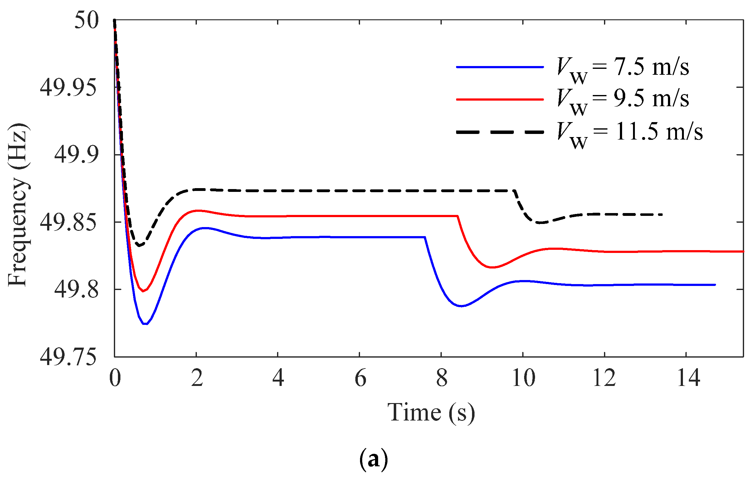
Table 2 shows that, with the variable droop coefficient, the active power reserve of the DFIG is better utilized both under medium and high wind speeds, leading to reduced steady-state frequency deviations. As can be seen from
Figure 10a, under a high wind speed, the DFIG is capable of further increasing its active power output through the adjustment of the droop coefficient, yielding a smaller system frequency deviation compared with the medium wind speed scenario. The enhanced frequency regulation capability brought by the variable droop coefficient setting also helps to relieve the pressure on the SES to participate in the frequency regulation, thus increasing its operation time before switching out, as shown in
Figure 10b.
Figure 10 reveals that the third of the three issues discussed in the Introduction, i.e., the full utilization of the frequency regulation capability by the DFIG, can be achieved through the adopted variable droop scheme and helps to improve the frequency regulation capability of the whole DFIG-SES system.


