Article

A Finite Element Analysis Model-Based Study on the Effect of the Frame on Membrane Stresses in Proton Exchange Membrane Fuel Cells

1
Horizon Fuel Cell Technologies (Shanghai) Co., Ltd., 999 Shan’lian Road, Shanghai 201804, China
2
School of Automotive Studies, Tongji University (Jiading Campus), 4800 Cao’an Road, Shanghai 201804, China
3
Clean Energy Automotive Engineering Center, Tongji University (Jiading Campus), 4800 Cao’an Road, Shanghai 201804, China
*
Author to whom correspondence should be addressed.
Energies 2023, 16(20), 7044; https://doi.org/10.3390/en16207044
Submission received: 19 August 2023 / Revised: 27 September 2023 / Accepted: 30 September 2023 / Published: 11 October 2023
(This article belongs to the Special Issue Advanced Manufacturing of Fuel Cells and Fuel-Cell Components)

Abstract

:
The frame of a membrane electrode assembly (MEA) has an important impact on durability and reliability of a proton exchange membrane fuel cell (PEMFC). In this study, the finite element analysis method has been used to build a two-dimensional model that can quickly screen and compare different frame structures and improve the design. Simulation results show that the membrane in the gap between the frame and the active area will generate a large amount of stress, close to the yield strength of the membrane under this condition, after application of the pressure difference. Further, an appropriate frame structure can improve the structural consistency between the frame and the area with moving materials, reduce membrane stress and improve reliability. The problem of stress concentration on the membrane at the joint area is solved by introducing a double-layer frame structure to limit membrane deformation. Hence, this can effectively alleviate the impact of the gap at the joint area and improve the durability of MEA.

1. Introduction

In recent years, various energy and environmental problems have gradually emerged from the exploitation of fossil fuels. Promoting the use of renewable energy sources, such as solar, wind and hydrogen, has become a consensus among countries around the world [1,2,3]. Most renewable energy sources are intermittent, leaving spatial and temporal gaps between the availability of the energy and its consumption by end users. To address these issues, it is necessary to develop suitable energy storage and generating systems for the power grid [4]. It is worth noting that the proton exchange membrane fuel cell (PEMFC), as a new type of power device, has the advantages of high thermal efficiency, large working current, short cold start time, and zero emission as well as having simple structure and movable parts [5,6]. However, the cost and durability of stacks and the infrastructure construction of hydrogen refueling stations limit the promotion of fuel cell vehicles [7]. The goal of the U.S. Department of Energy (DOE) on durability of fuel cell systems for transportation is 5000 h, which is a difficult target to achieve globally [8]. To improve the durability, researchers have conducted many innovative studies on materials, components and systems [9]. Generally speaking, previous research studies have mainly focused on membrane electrode components, such as gas diffusion layer (GDL), proton exchange membrane (PEM) and catalytic layer (CL) [10,11], and not enough attention has been paid to the frame sealing structure on the edge of the MEA [12]. Early fuel cell failure tends to occur near the frame seal in preference to component damage. Therefore, a reasonable frame structure design is very important to improve durability [13].
Indeed, the PEM in the working environment is susceptible to chemical and mechanical influences, such as dry/wet cycling, localized hot spots, catalyst stripping and dissolution [14,15]. Hydrogen peroxide free radicals will attack the membrane, causing it to become thinner and cracked [16]. Mechanical degradation at the frame is considered to be the main cause of early fuel cell failure [17]. At present, although additional frame structures are used to protect the PEM and prevent premature failure, the current frame structure still exhibits some problems [18]. Qiu et al. [19] pointed out that the joint area of the frame and the active area exposed to the working environment is a weak place for mechanical degradation. Moreover, the clamping force during stack clamping, the gas pressure impact during work and the gas pressure difference between the anode and cathode as well as the damp heat stress caused by the temperature/humidity changes in the stack may cause cracks and pinholes in the membrane [20,21].
Bates et al. [22] conducted a three-dimensional simulation analysis of the stack and found that the clamping force is mainly borne by the seal. The pressure in the active area of the MEA was also found to be lower than that at the frame. Further, an improper clamping force may cause leakage and rupture of brittle internal parts. Elsewhere, Alizadeh et al. [23] reached a similar conclusion through simulation and experiment. The contact pressure under the sealing ring increases sharply and the harder the seal, the more the stress concentration occurs at the frame. The heat and humidity cycles induce hygro-thermal stress, during which the stress in the membrane may reach the yield limit. Many researchers use a two-dimensional single-channel simulation model to study the influence of heat and humidity cycles on the membrane [20,24,25]. The results of various studies show that the in-plane stress is the largest stress component during the loading process, and it controls the yield behavior. The finite element simulation study indicated that the pressure difference may be the main reason for early failure of the MEA frame. The pressure difference between the anode and cathode after the reactant gas is introduced into the fuel cell leads to a rapid increase in the in-plane of the membrane. Assembly error of the bipolar plate may lead to a larger stress distribution on the membrane. The material and size of the frame and gasket as well as the material and design of the bipolar plate have an important influence on the reliability of the sealing structure [26].
Several studies have reported that factors such as clamping force and gas pressure difference cause stress concentration at the frame of the MEA, which may cause mechanical damage [27]. However, relevant research is still lacking on how to improve the frame structure design. In this study, the finite element analysis method is used to analyze the stress response of the frame on the PEM under the pressure of the clamping and pressure difference. The influence rules are obtained by changing the frame structure, materials and other factors, to guide the MEA frame design. Introducing a double-layer frame structure, by changing the structural design to limit deformation of the membrane, can effectively alleviate the impact of the gap at the joint area.

2. Finite Element Simulations

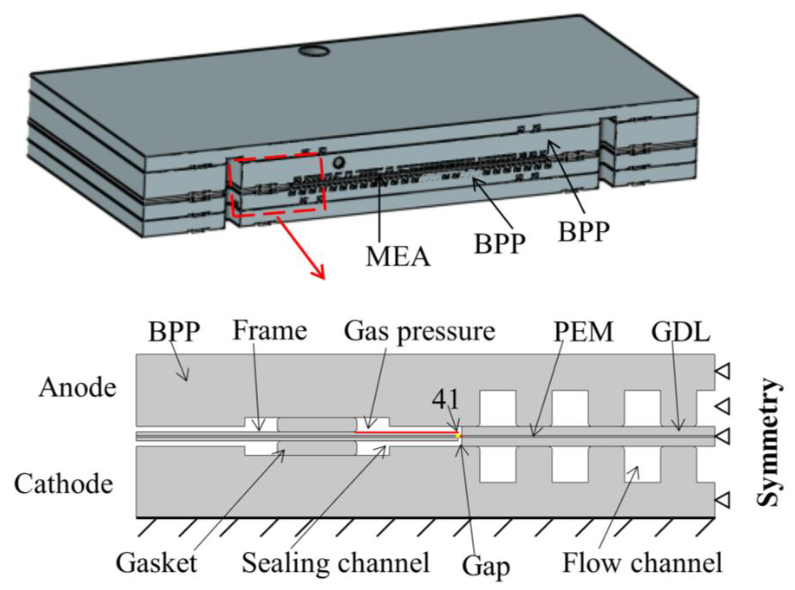
2.1. Model and Assumption

This study mainly evaluated the influence of frame material, size and other factors on membrane stress. A typical cross-section of the fuel cell was selected using the two-dimensional model shown in Figure 1. The model includes cathode and anode bipolar plates (BPP), gasket, frame, PEM and GDL. A two-dimensional model was used for simulation considering that the size of the single cell module in the thickest direction is much smaller than in other directions. Furthermore, the stress concentration caused by clamping is mainly in the direction perpendicular to the plane [28]. The model not only focuses on the key areas of research, but also can save computing resources and reduce model complexity.
To simplify the complexity of the model without affecting the accuracy of the finite element simulation results of the area of interest, the following assumptions were proposed: (1) The influence of the electrochemical reaction of the fuel cell is not considered in the model. The main concern is the mechanical stress response between the components at the MEA frame, regardless of the heat and moisture generated by the electrochemical reaction and the influence of the uneven distribution. (2) The creep effect and time-related properties of the material are not considered. Previous studies have shown that fuel cell components such as PEM, gaskets and other materials have a certain degree of creep, and the material properties are time-dependent. This study was a steady-state study. Except for gaskets, the materials in the model were assumed to be linear elastic and isotropic and the gasket adopts a hyper-elastic model. (3) The influence of the thickness and mechanical properties of the CL are ignored. The thickness of the CL is much thinner than other components and its mechanical properties have little influence in this study. Therefore, the influence of the CL is ignored, and it is integrated into the GDL to form a gas diffusion electrode (GDE). (4) The model considers the effect on the proton exchange membrane of the clamping force and withstanding pressure differences at an ambient temperature of 25 °C and 30% humidity. The effect of increasing temperature and humidity in the working environment is not introduced. Furthermore, COMSOL Multiphysics® finite element simulation software was used for modeling and solving [29].
To calculate the stress and deformation state of the components in the finite element model, two-dimensional plane strain was used. Considering the large difference in the structural size of the components in the model, to strike a balance between the calculation accuracy and the complexity, a fine element was meshed for PEM, frame, GDE and seal, as well as in the possible stress concentration area. The complete mesh of the model contains 27,147 domain elements and 6052 boundary elements. Two contact behaviors were defined in the model. The contact pair between the frame and PEM, GDL and PEM adopts the adhesion characteristics to simulate hot pressing and adhesion in the actual production process of MEA. The remaining contact pairs add frictional contact between the two surfaces. The contact pressure calculation determines the method of the penalty function. The penalty function method does not increase the degree of freedom of the problem, the coefficient matrix remains positive, definite and easy to solve, which is widely used in contact analysis [30].

2.2. Material Properties

In the model, the size parameters of BPPs and gaskets were measured from physical objects. Considering that the modulus of elasticity of BPP materials, whether metal or graphite, is higher than that of other MEA components, the mechanical properties of BPP have less influence on the stress state of the PEM [31]. In this study, the thickness of the anode and cathode bipolar plates was the same (2 mm). To simplify the model, water channel on the BPPs was ignored. The frame material adopted the commonly used polyethylene naphthalate (PEN) plastic. The material properties of the graphite bipolar plate and frame used the material properties of commercial graphite and PEN plastic.
The gas diffusion layer is usually carbon paper or carbon cloth. The PEM is Nafion®112 membrane (298.15 K, 30% RH) produced by DuPont, with a thickness of 0.05 mm. Table 1 lists the size parameters of each component in the model. In the manufacture of MEAs, the frame is usually attached to the surface of the membrane by means of hot pressing or glue bonding. Due to design tolerances and manufacturing errors, the frame cannot be completely aligned with the GDL, and gaps exist as shown in Figure 1. It is assumed that the gap between the frame and the GDE is 0.1 mm. The BPP, GDE, frame and PEM are assumed to be linear elastic materials. The material parameters of GDL and PEM come from the literature [32]. Table 2 shows the material parameters of the above-mentioned components.
The constitutive law between stress and strain is given by Hooke’s law.
σ i j = E ( 1 + v ) ( 1 2 v ) v ε V e l + ( 1 2 v ) ε i j e l
where σ i j is the stress tensor, E represents the elastic modulus of the material and v is Poisson’s ratio. ε i j e l represents the strain tensor in the elastic phase i , j = x , y and ε V e l = ε x x + ε y y + ε z z .
The gasket material was silicone rubber because rubber materials deform greatly after compression and their stress and deformation behaviors are highly nonlinear. The constitutive relationship is usually described as the strain energy function described in polynomial form [33,34] and the stress tensor is not uniquely determined by deformation [35].
This study adopted the Mooney–Rivlin model based on the polynomial model of the strain energy function, assuming that the rubber material is isotropic and incompressible. The first-order two-parameter Mooney–Rivlin model can be expressed as:
σ i j = W ε i j
W = C 10 I ¯ 1 3 + C 01 ( I ¯ 2 3 )
In Equation (3), W is the strain energy function, I ¯ 1 and I ¯ 2   are the first and second invariants of deviatoric strain, C 10   and C 01 are material constants, listed in Table 3 which is obtained by regression fitting of experimental data.

3. Finite Element Analyses Results

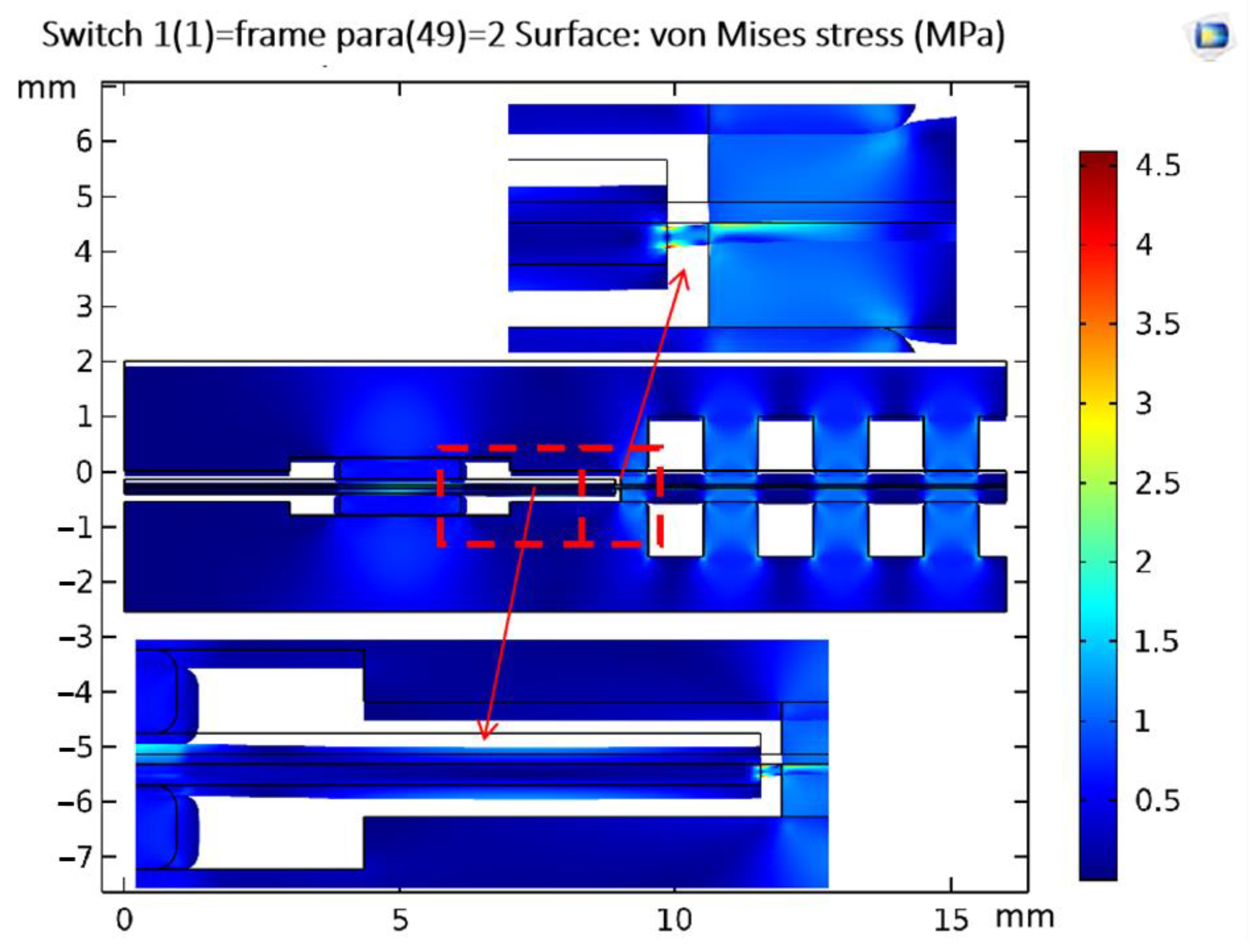
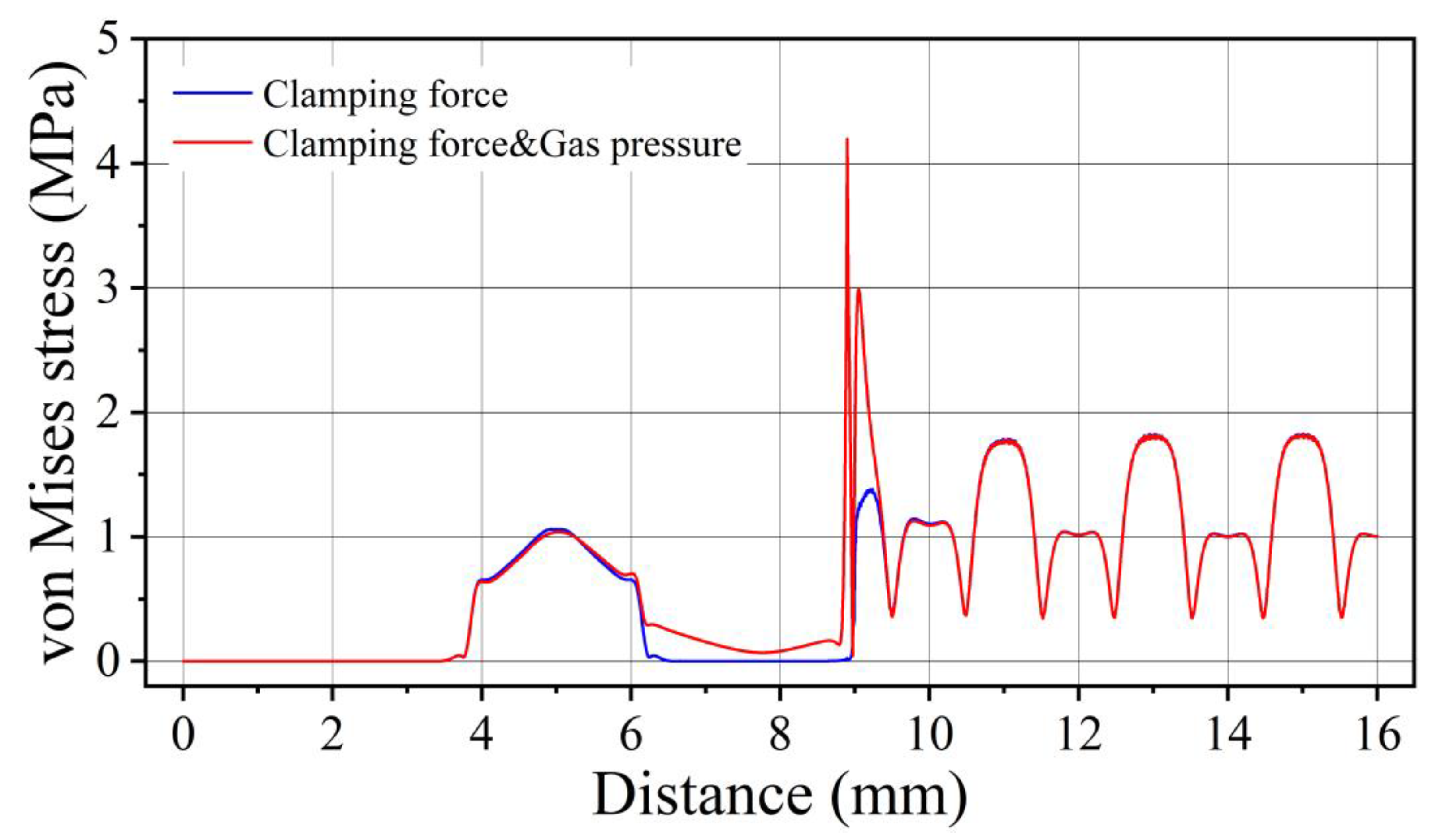
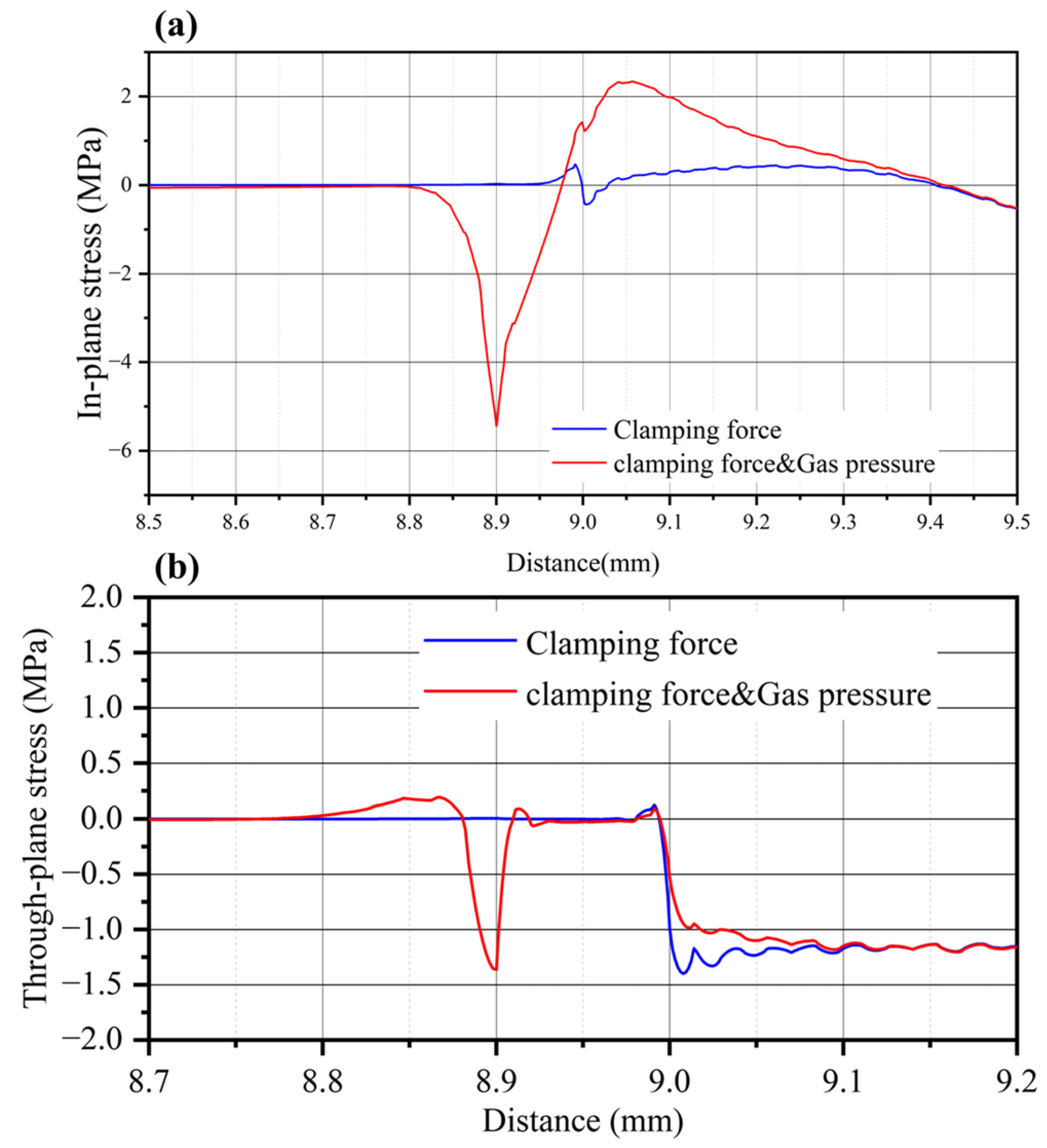
3.1. Stress–Strain Response on Membrane

The cathode and anode reactant gases fill into the fuel cell through the intake manifold when the fuel cell is in operation. A pressure difference of tens of kilopascals between the anode and cathode occurs. The pressure difference may be even greater during the start–stop phase. Therefore, the gas pressure difference will have a greater impact on the membrane along the gap of the frame. To study the influence of the gas pressure on the membrane, a pressure boundary load of 20 kPa was applied to the anode side in the model, as shown in Figure 2.
The simulation results showed that under the action of the pressure difference, the frame bends and deforms toward the cathode side close to the cathode bipolar plate. On one side of the active area, the flow channel ridges compressed the MEA to limit further deformation of the frame and membrane. It should be noted that the frame was generally deformed. However, the place closest to the cathode bipolar plate (where the deformation is greatest) is not the end of the active area of the frame, but the middle position between the seal and the end of the active area. This is closer to the active area. The membrane drags the end of the frame to limit its further downward movement and is torn, which increases stress on the membrane. The model von Mises stress cloud diagram under the combined action of clamping force and pressure difference is shown in Figure 2. The stress on the side of the frame close to the active area increases under the action of the pressure difference. Stress on the membrane at the gap between the frame and active area increases significantly and concentrates at the end of the frame. More precisely, as shown in Figure 3 (the gap is between 8.9 and 9 mm), stress concentration appears on the membrane under the frame after the reactant gas is filled to produce a pressure difference and the local stress increases to 4.20 MPa (close to the yield stress of 6.75 MPa under this condition).
After the pressure was applied, the tension and compression state of the frame and the surface of the membrane in the active area changed. As shown in Figure 4, taking the anode side of the membrane as an example, the membrane at the joint of the frame and active area is in a compressed state after the clamping force is applied and the in-plane stress (stress tensor sl11, along the x direction) has a negative value. This is due to the extrusion deformation of the gasket and where the flow channel lands when the MEA is clamped. After the gas pressure difference was applied, the internal stress increased significantly. The membrane stress at the end of the frame reached −5.44 MPa. At a certain position of gap, the internal stress on the membrane becomes positive, changing from the compressed state to the tensile state. The pressure difference offsets the compression deformation of the membrane during the clamping process and the stress changes alternately. The membrane through-plane stress (stress tensor sl22, along the y direction) also increased at the end of the frame and GDL. In general, the frame deformed after the gas pressure difference was applied to the membrane in the joint area. As a result, the stress on the membrane in the joint area increased significantly and stress concentration occurred at the ends of the frames. Both the in-plane stress and the through-plane stress increased to varying degrees and the in-plane stress played a leading role. The tension and compression state of the membrane changed after gas filling and the alternating stress significantly reduced the fatigue life of the membrane.

3.2. Analysis of Influencing Factors

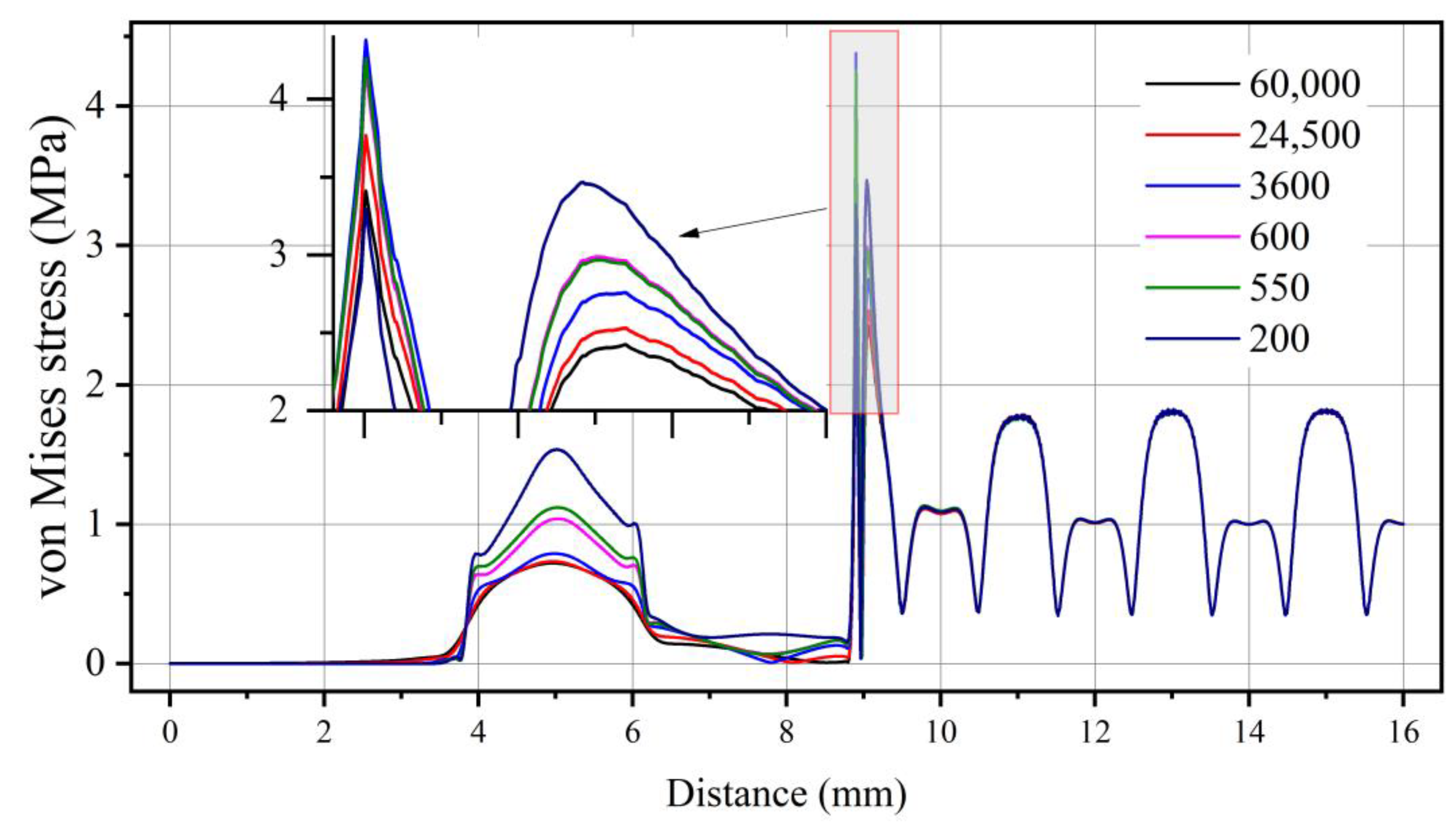
3.2.1. Frame Material

The stress concentration occurred on the membrane at the gap of the frame and active area during assembly and operation of the fuel cell. The deflection of the frame after gas filling is the main reason for the large stress on the membrane. Therefore, selecting a suitable frame material may be a very important factor in improving the stress state of the membrane along the frame when the fuel cell is working. To study the influence of frame material on the stress response of the membrane, different materials were assigned to the frame without changing the geometric model and the setting of the boundary conditions. In this analysis, six materials with different properties were used in two material types: composite material and macromolecular material. The material properties were obtained from the literature [14] and the specific material properties were as shown in Table 4.
Taking the anode side as an example, the membrane stress distribution after gas filling was as shown in Figure 5. There was a big difference in the stress distribution on the membrane under the gaskets. It was found that the higher the elastic modulus, the smaller the stress on the membrane. Taking the elastic modulus as the material number, the stress on the membrane corresponding to the center of the gasket was 200 (1.53 MPa), 550 (1.12 MPa), 600 (1.04 MPa), 3600 (0.79 MPa), 24,500 (0.73 MPa) and 60,000 (0.72 MPa). Near the end of the frame and GDL, points with greater stress appeared on the membrane.
The stress at the end of the GDL was negatively related to the elastic modulus of the material. This is because the smaller the elastic modulus of the frame, the greater the degree of deflection under the action of the gas pressure. The stress at the end of the frame was 3600, 550, 600, 24,500, 60,000 and 200, in descending order. This may be because the larger the elastic modulus of the frame, the smaller the deflection of the frame. On the other hand, the rigidity of the frame was prone to stress concentration. Membrane stresses in the connection area are the combined result of bending deformation due to gas pressure and localized stress concentrations of the frame. When the elastic modulus of the frame is large, the degree of deflection is small and less likely to pull on the membrane. When the modulus of elasticity is greater, the effect of stress concentrations may begin to be felt.

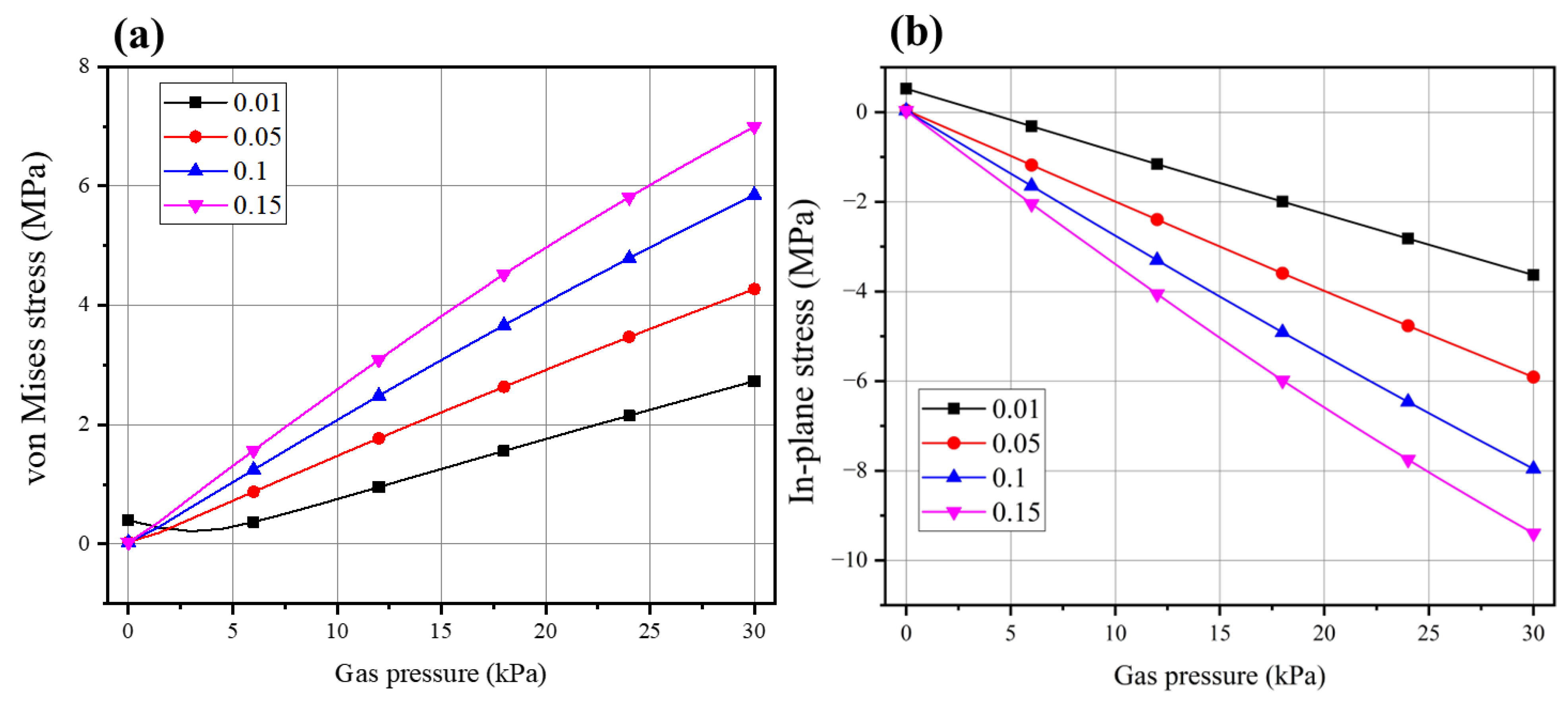
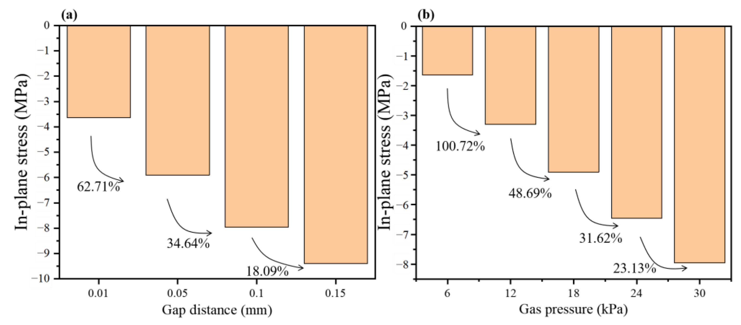
3.2.2. Gas Pressure and Gap Width

In order to study the influence of the gas pressure difference and the gap between the frame and active area, the gap width between the end of the frame and the end of the GDL was set to 0.01, 0.05, 0.1 and 0.15 mm. The gap between the frame and MEA cannot be eliminated during the production of the single-layer frame MEA. Further, gaps may appear around the periphery of the entire MEA active area. When the pressure difference loaded in the model was changed, the maximum pressure difference was 30 kPa and this value is possible in fuel cell operation. Take 41 at the end of the anode frame of the membrane as the observation point of stress (shown in Figure 1).
As shown in Figure 6, the absolute value of the von Mises stress and the in-plane stress at point 41 increased with the increase of the cathode and anode gas pressure difference. The gap width also increased from 0.01 to 0.1 with the gas pressure difference. The in-plane stress at point 41 increased rapidly when the gap width increased from 0.1 to 0.15 but the growth rate slowed down. This may be because the gap width reached a certain level and the deformation of the membrane at the gap became smooth.
The maximum in-plane stress (anode side) of the handover area was used as an evaluation index to compare the influence of the gap width and the air pressure difference. The change of the in-plane stress with the gap width when the air pressure difference was 30 kPa is shown in Figure 7. When the gap width and the air pressure difference changed, the internal stress on the membrane also changed greatly. In comparison, it was found that the in-plane stress is more sensitive to the change of the pressure difference. Therefore, the large pressure fluctuations and the pressure difference between the anode and the cathode should be avoided when the fuel cell is working. In addition, the membrane at the joint was exposed to the hot and humid environment when the fuel cell was working. The expansion of the membrane thus caused more serious stress concentration. Therefore, measures should be taken to protect the membrane at the gap or the frame design should be changed to avoid gaps.

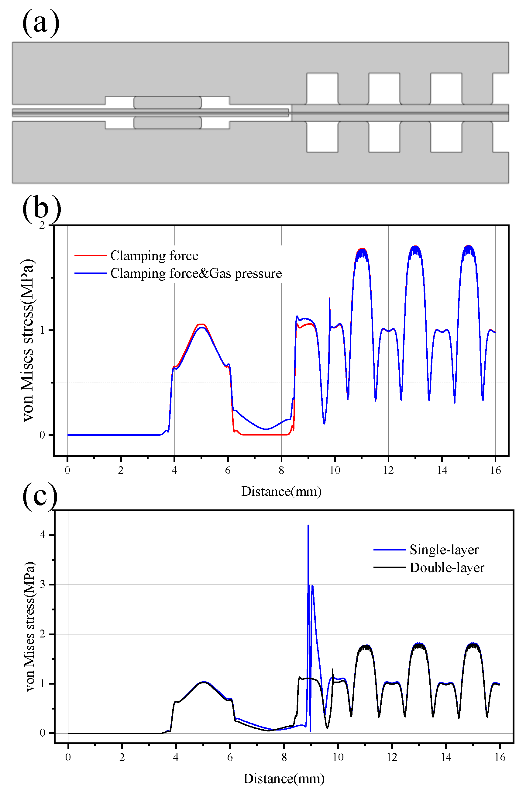
3.3. Double-Layer Frame Structure

Having gaps at the joint of the frame and active area is a problem of a single-layer frame structure. The proton exchange membrane exposed to the gap under the action of the pressure difference generated during the operation of the fuel cell undergoes stress concentration and this may cause early damage. When temperature and humidity change, the membrane at the joint will repeatedly expand and contract to produce fatigue stress. These shortcomings of the single-layer frame are overcome with the double-layer frame structure shown in Figure 8a, which is also beneficial to improve the reliability of the fuel cell.
Double-layer frame means that there are two layers of frame on the anode (cathode) side. One layer of sub-frame (substrate frame) is glued to the membrane, whereas the other layer is attached to the sub-frame (Figure 8a). The double-layer frame has the following advantages as compared with the single-layer frame: (1) It eliminates the gap between the frame and active area. The double-layer frame can use a thinner sub-frame liner under the gas diffusion layer to eliminate the gap and limit the expansion and deformation of the membrane. (2) The end of the GDL covers the sub-frame instead of directly contacting the proton exchange membrane. To shorten the frame length from the seal to the GDL without restriction of expansion and contraction, the GDL extends to the seal side. The single-layer frame structure may cause the problem of stray fibers piercing the proton exchange membrane after the GDL is installed and compressed. (3) The sub-frame, as a protective layer, can bear the pressing force and reduce the effect of the force transmitted to the membrane.
To verify the above analysis, the installation force and air pressure difference were applied to the single-layer and double-layer frame structures and the response of the membrane along the frames was compared. The two structural frames use the same material as listed in Table 2. The thicknesses of the two layers of the double-layer frame are 0.06 mm and 0.04 mm, respectively.
Addition of a sub-frame can effectively reduce the negative impact caused by the air pressure difference (Figure 8b). After the air pressure difference is applied, the stress on the membrane increased slightly compared to when only the installation force is applied and the frame between the seal and the GDL is deformed by the air pressure difference. There is a slight stress concentration on the membrane at the end of the sub-frame because the overall compression deformation caused by the bipolar plate pressing the gas diffusion layer and the sub-frame. The simulation using a rectangle to represent the geometric shape of the frame may also cause stress concentration. The stress level on the double-layer frame proton exchange membrane is smaller as compared with the single-layer frame structure with gaps. Further, elimination of the gap on the double-layer frame proton exchange membrane significantly reduces the force effect caused by the pressure difference. The stress change on the membrane at the frame is more gradual, the maximum stress is about a fourth of the single-layer frame structure, and there is no significant stress rise at the gap of the single-layer frame. The stress distribution at the frame of the double-layer structure is basically at the same level as the active area. Figure 8c shows the comparison of the stress distribution on the anode side membrane of the two structures. The double-layer frame structure uses a larger GDL coverage length and the end position of the GDL is closer to the origin of the x coordinate.
In conclusion, the influence of these factors on the stress and deformation of the membrane at the frame was analyzed by changing the geometric model of the finite element analysis, frame material, gap width, and the applied pressure difference.
  • Frequent gas pressure changes and large gas pressure differences between the anode and cathode may have caused early damage to the membrane at the gap.
  • The higher the modulus of elasticity, the stronger the ability to bear the installation clamping force, the smaller the stress of the membrane under the seal and the smaller the degree of deflection of the frame caused by the air pressure difference. The greater the rigidity of frame material, the more likely it is to cause stress concentration at the end of the frame.
  • As the air pressure difference increased, the length of the gap at the joint also increased and the stress on the membrane will increase accordingly. The stress on the membrane at the joint is more sensitive to the air pressure difference. By changing the frame material, reducing the length of the transfer area can reduce the impact of the pressure difference to a certain extent. However, this does not fundamentally solve the problem. Therefore, appropriate control strategies should be adopted to avoid frequent changes in air pressure and large air pressure difference between anode and cathode during fuel cell operation. Measures should be taken to eliminate the gaps in the joint area to avoid direct exposure of the membrane to the harsh environment of fuel cell operation.
  • The double-layer frame is a better structure compared to the single-layer frame. Modifying the frame based on existing processing technology is a structure that can achieve better performance. The double-layer frame eliminates the gap at the joint and can effectively reduce the impact of pressure difference. The stress level on the membrane at the frame is smaller than the active area and the distribution is more even.

4. Conclusions

In this paper, the finite element analysis method is used to comprehensively analyze the influence of frame material, size and structure on the stress of proton exchange membrane. When the fuel cell is working, as the internal temperature, humidity and air pressure change, the components at the frame deform unevenly and asynchronously. The membrane in the boundary area becomes the “compromise point” of deformation between the frame and active area, which is prone to damage. Considering the effect of clamping force and gas pressure difference, the load-bearing part of the frame should be larger than the membrane in terms of modulus of elasticity. The simulation results show that the composite membrane has better stress performance and less tearing of the membrane. And the elastic modulus of the frame part, which is the connection active zone, should be close to the membrane material, which can ensure good stress consistency of the membrane. This article points out that changing the frame structure and improving the continuity of the structure and materials between the frame and active area is the key to improving durability. Introducing a double-layer frame structure can effectively mitigate the effect of the gap at the joint area, resulting in a more even distribution of membrane stress. The finite element analysis reveals the stress and deformation of the components at the frame, which helps to analyze the fatigue life of the frame seal structure with complex interaction relationships. With this method, different frame structures can be quickly compared, and a suitable frame structure can be screened.

Author Contributions

Conceptualization, Z.Z. and Y.T.; Methodology, Z.Z. and Y.T.; Software, Y.T. and D.Y.; Validation, Z.Z. and Y.T.; Formal analysis, Z.Z. and T.C.; Investigation, Z.Z. and Y.T.; Resources, B.L.; Data curation, Z.Z. and D.Y.; Writing–original draft, Z.Z. and Y.T.; Writing–review and editing, T.C. and B.L.; Visualization, T.C. and B.L.; Supervision, T.C.; Funding acquisition, B.L. All authors have read and agreed to the published version of the manuscript.

Funding

This research was funding by the Ministry of Science & Technology of the People’s Republic of China (No. 2020YFB0106601).

Data Availability Statement

Data sharing not applicable.

Acknowledgments

The authors appreciate the Ministry of Science & Technology of the People’s Republic of China (No. 2020YFB0106601) for financial support.

Conflicts of Interest

The authors declared that they have no conflicts of interest to this work. We declare that we do not have any commercial or associative interest that represents a conflict of interest in connection with the work submitted.

References

  1. Jewell, J.; McCollum, D.; Emmerling, J.; Bertram, C.; Gernaat, D.; Krey, V.; Paroussos, L.; Berger, L.; Fragkiadakis, K.; Keppo, I.; et al. Limited emission reductions from fuel subsidy removal except in energy-exporting regions. Nature 2018, 554, 229–233. [Google Scholar] [CrossRef]
  2. Razi, F.; Dincer, I. Renewable energy development and hydrogen economy in MENA region: A review. Renew. Sustain. Energy Rev. 2022, 168, 112763. [Google Scholar] [CrossRef]
  3. Squadrito, G.; Maggio, G.; Nicita, A. The green hydrogen revolution. Renew. Energy 2023, 216, 119041. [Google Scholar]
  4. Sun, C.; Negro, E.; Vezzù, K.; Pagot, G.; Cavinato, G.; Nale, A.; Herve Bang, Y.; Di Noto, V. Hybrid inorganic-organic proton-conducting membranes based on SPEEK doped with WO3 nanoparticles for application in vanadium redox flow batteries. Electrochim. Acta 2019, 309, 311–325. [Google Scholar]
  5. Jiao, K.; Xuan, J.; Du, Q.; Bao, Z.; Xie, B.; Wang, B.; Zhao, Y.; Fan, L.; Wang, H.; Hou, Z.; et al. Designing the next generation of proton-exchange membrane fuel cells. Nature 2021, 595, 361–369. [Google Scholar]
  6. Wu, S.; Salmon, N.; Li, M.; Bañares-Alcántara, R.; Tsang, S. Energy Decarbonization via Green H2 or NH3? ACS Energy Lett. 2022, 7, 1021–1033. [Google Scholar] [CrossRef]
  7. Li, J.; Fang, C.; Xu, L. Current status and trends of the research and development for fuel cell vehicles. J. Automot. Saf. Energy 2014, 5, 17. [Google Scholar]
  8. Thompson, S.; Wilson, A.; Zelenay, P.; Myers, D.; More, K.; Neyerlin, K.; Papageorgopoulos, D. ElectroCat: DOE’s approach to PGM-free catalyst and electrode R&D. Solid State Ion. 2018, 319, 68–76. [Google Scholar]
  9. Mustain, W.; Chatenet, M.; Page, M.; Kim, Y.S. Durability challenges of anion exchange membrane fuel cells. Energy Environ. Sci. 2020, 13, 2805–2838. [Google Scholar]
  10. Yan, S.; Yang, M.; Sun, C.; Xu, S. Liquid Water Characteristics in the Compressed Gradient Porosity Gas Diffusion Layer of Proton Exchange Membrane Fuel Cells Using the Lattice Boltzmann Method. Energies 2023, 16, 6010. [Google Scholar] [CrossRef]
  11. Zhang, S.; Yuan, X.; Wang, H.; Mérida, W.; Zhu, H.; Shen, J.; Wu, S.; Zhang, J. A review of accelerated stress tests of MEA durability in PEM fuel cells. Int. J. Hydrogen Energy 2009, 34, 388–404. [Google Scholar] [CrossRef]
  12. Stariha, S.; Macauley, N.; Sneed, B.; Langlois, D.; More, K.; Mukundan, R.; Borup, R. Recent advances in catalyst accelerated stress tests for polymer electrolyte membrane fuel cells. J. Electrochem. Soc. 2018, 165, F492. [Google Scholar] [CrossRef]
  13. Pahon, E.; Hissel, D.; Yousfi-Steiner, N. A review of accelerated stress tests dedicated to proton exchange membrane fuel cells—Part I: Fuel cell component level. J. Power Sources 2022, 546, 231895. [Google Scholar]
  14. Lim, C.; Ghassemzadeh, L.; Van Hove, F.; Lauritzen, M.; Kolodziej, J.; Wang, G.G.; Holdcroft, S.; Kjeang, E. Membrane degradation during combined chemical and mechanical accelerated stress testing of polymer electrolyte fuel cells. J. Power Sources 2014, 257, 102–110. [Google Scholar] [CrossRef]
  15. Yang, W.; Guo, H.; Niu, F.; Wang, B.; Huang, B.; Niu, S.; Liu, J.; Yang, S.; Yang, Y. A novel strategy for accelerating degradation of proton exchange membranes in fuel cell. Renew. Energy 2023, 213, 38–46. [Google Scholar] [CrossRef]
  16. Shimizu, R.; Tsuji, J.; Sato, N.; Takano, J.; Itami, S.; Kusakabe, M.; Miyatake, K.; Iiyama, A.; Uchida, M. Durability and degradation analysis of hydrocarbon ionomer membranes in polymer electrolyte fuel cells accelerated stress evaluation. J. Power Sources 2017, 367, 63–71. [Google Scholar] [CrossRef]
  17. Crum, M.; Liu, W. Effective Testing Matrix for Studying Membrane Durability in PEM Fuel Cells: Part 2. Mechanical Durability and Combined Mechanical and Chemical Durability. ECS Trans. 2006, 3, 541. [Google Scholar] [CrossRef]
  18. Zhang, Y.; Gao, Z.; Wei, L.; Su, J. Improving the Performance of PEM Fuel Cells: Form a Patterned Hydrophobic Catalyst Layer. J. Electrochem. Soc. 2023, 170, 054508. [Google Scholar] [CrossRef]
  19. Qiu, D.; Peng, L.; Liang, P.; Yi, P.; Lai, X. Mechanical degradation of proton exchange membrane along the MEA frame in proton exchange membrane fuel cells. Energy 2018, 165, 210–222. [Google Scholar] [CrossRef]
  20. Kusoglu, A.; Karlsson, A.M.; Santare, M.H.; Cleghorn, S.; Johnson, W.B. Mechanical behavior of fuel cell membranes under humidity cycles and effect of swelling anisotropy on the fatigue stresses. J. Power Sources 2007, 170, 345–358. [Google Scholar] [CrossRef]
  21. Li, B.; Kim, Y.S.; Mukundan, R.; Wilson, M.S.; Welch, C.; Fenton, J.; Borup, R.L. Mixed Hydrocarbon/Fluoropolymer Membrane/Ionomer MEAs for Durablity Studies. ECS Trans. 2010, 33, 913. [Google Scholar] [CrossRef]
  22. Bates, A.; Mukherjee, S.; Hwang, S.; Lee, S.C.; Kwon, O.; Choi, G.H.; Park, S. Simulation and experimental analysis of the clamping pressure distribution in a PEM fuel cell stack. Int. J. Hydrogen Energy 2013, 38, 6481–6493. [Google Scholar] [CrossRef]
  23. Alizadeh, E.; Barzegari, M.M.; Momenifar, M.; Ghadimi, M.; Saadat, S.H.M. Investigation of contact pressure distribution over the active area of PEM fuel cell stack. Int. J. Hydrogen Energy 2016, 41, 3062–3071. [Google Scholar] [CrossRef]
  24. Kusoglu, A.; Santare, M.H.; Karlsson, A.M. Aspects of fatigue failure mechanisms in polymer fuel cell membranes. J. Polym. Sci. Part B Polym. Phys. 2011, 49, 1506–1517. [Google Scholar] [CrossRef]
  25. Khattra, N.S.; Karlsson, A.M.; Santare, M.H.; Walsh, P.; Busby, F.C. Effect of time-dependent material properties on the mechanical behavior of PFSA membranes subjected to humidity cycling. J. Power Sources 2012, 214, 365–376. [Google Scholar] [CrossRef]
  26. Liu, D.; Peng, L.; Lai, X. Effect of assembly error of bipolar plate on the contact pressure distribution and stress failure of membrane electrode assembly in proton exchange membrane fuel cell. J. Power Sources 2010, 195, 4213–4221. [Google Scholar] [CrossRef]
  27. Liang, P.; Qiu, D.; Peng, L.; Yi, P.; Lai, X.; Ni, J. Structure failure of the sealing in the assembly process for proton exchange membrane fuel cells. Int. J. Hydrogen Energy 2017, 42, 10217–10227. [Google Scholar] [CrossRef]
  28. Ye, D.H.; Zhan, Z.G.; Lee, Y.J.; Tu, Z.K.; Zhang, Y.; Pan, M. Effects of Frame Materials and Structures on Stress Concentration of Membrane Electrode Assembly of PEMFCs. Fuel Cells 2013, 13, 1205–1212. [Google Scholar] [CrossRef]
  29. Yao, J.; Yan, F.-Y.; Pei, X.-J. Bionic flow field research and optimization of PEMFC with multi-branch veins. Chem. Pap. 2023, 77, 935–946. [Google Scholar] [CrossRef]
  30. Stefancu, A.; Melenciuc, S.; Budescu, M. Construction. Architecture Section, Penalty Based Algorithms for Frictional Contact Problems. Bull. Polytech. Inst. Jassy Constr. 2011, 57, 119–130. [Google Scholar]
  31. Lu, Z.; Kim, C.; Karlsson, A.M.; Cross, J.C.; Santare, M.H. Effect of gas diffusion layer modulus and land–groove geometry on membrane stresses in proton exchange membrane fuel cells. J. Power Sources 2011, 196, 4646–4654. [Google Scholar] [CrossRef]
  32. Liu, W.; Qiu, D.; Peng, L.; Yi, P.; Lai, X. Mechanical degradation of proton exchange membrane during assembly and running processes in proton exchange membrane fuel cells with metallic bipolar plates. Int. J. Energy Res. 2020, 44, 8622–8634. [Google Scholar] [CrossRef]
  33. Wei, C.; Lu, A.; Sun, S.; Wei, X.; Zho, X.; Sun, J. Establishment of Constitutive Model of Silicone Rubber Foams Based on Statistical Theory of Rubber Elasticity. Chin. J. Polym. Sci. 2018, 36, 1077–1083. [Google Scholar] [CrossRef]
  34. Peng, X.; Han, L.; Li, L. A consistently compressible Mooney-Rivlin model for the vulcanized rubber based on the Penn’s experimental data. Polym. Eng. Sci. 2021, 61, 2287–2294. [Google Scholar] [CrossRef]
  35. Wu, B.; Zhao, M.; Shi, W.; Liu, W.; Liu, J.; Xing, D.; Yao, Y.; Hou, Z.; Ming, P.; Gu, J.; et al. The degradation study of Nafion/PTFE composite membrane in PEM fuel cell under accelerated stress tests. Int. J. Hydrogen Energy 2014, 39, 14381–14390. [Google Scholar] [CrossRef]
Figure 1. Schematic diagram of PEMFC and the finite element simulation model. The red line represents that a pressure boundary load of 20 kPa was applied to the anode side in the model. Take 41 (yellow dot) at the end of the anode frame of the membrane as the observation point of stress.
Energies 16 07044 g001
Figure 2. The stress and strain distribution of the components in the model under clamping force and gas pressure.
Energies 16 07044 g002
Figure 3. Stress distribution on the anode side of the membrane.
Energies 16 07044 g003
Figure 4. Stress tensors on the membrane at the joint area between the frame and MEA active area: (a) in-plane stress, (b) through-plane stress.
Energies 16 07044 g004
Figure 5. Stress response on the membrane when using different material frames under the conditions of clamping force and gas pressure.
Energies 16 07044 g005
Figure 6. Relationship between the von Mises stress (a) and the in-plane stress (b) at point 41 of different gap widths with the gas pressure.
Energies 16 07044 g006
Figure 7. Influence of gas pressure and gap width on the stress concentration of the membrane. (a) Change the gap width under the condition of 30 kPa gas pressure. (b) Change the gas pressure at 0.1 mm gap width.
Energies 16 07044 g007
Figure 8. (a) Schematic diagram of double-layer frame structure. (b) Stress distribution on the membrane of the double-layer frame structure. (c) Comparison of the stress distribution on the membrane of the two frame structures under the conditions of clamping force and gas pressure.
Energies 16 07044 g008
Table 1. Main size parameters of the finite element simulation model.
ParametersValue/(mm)
BPPThickness2
Flow channel/ridge width1
Flow channel/ridge height1
Sealing channel width4
GasketWidth2.2
Height0.4
GDL thickness0.25
Frame thickness0.1
Membrane thickness0.05
Table 2. Material parameters of finite element simulation model.
ComponentYoung’s Modulus/(MPa)Poisson’s RatioDensity/(kg/m3)
BPP10,0000.31800
Frame [29]6000.3900
GDL [28]90.09400
Membrane [19]1970.252000
Table 3. Mooney–Rivlin model coefficients of gasket.
Parameter C 10 C 01
Value/(MPa)0.599490.26034
Table 4. Different frame materials used in the simulation [14].
Material TypesYoung’s Modulus/(MPa)Poisson’s
Ratio
Density/(kg/m3)
Composite material60,0000.32540
Composite material24,5000.32000
Macromolecular material36000.381200
Macromolecular material6000.3900
Macromolecular material5500.46930
Macromolecular material2000.251900
Disclaimer/Publisher’s Note: The statements, opinions and data contained in all publications are solely those of the individual author(s) and contributor(s) and not of MDPI and/or the editor(s). MDPI and/or the editor(s) disclaim responsibility for any injury to people or property resulting from any ideas, methods, instructions or products referred to in the content.

