Review

Energy Harvesting and Storage Devices through Intelligent Flexographic Technology: A Review Article

by
Nuha Al Habis
1,*,
Muna Khushaim
2,3 and
Saja M. Nabat Al-Ajrash
4,5
1
Deputyship for Research & Innovation, Ministry of Education, P.O. Box 7271, Riyadh 13248, Saudi Arabia
2
Department of Physics, Faculty of Science, Taibah University, P.O. Box 30002, Al-Madina 41447, Saudi Arabia
3
Innovation and Strategic Research Labs, Taibah University, P.O. Box 30002, Al-Madina 41447, Saudi Arabia
4
Department of Chemical and Materials Engineering, University of Dayton, Dayton, OH 45469, USA
5
Department of Chemical Engineering, University of Kufa, P.O. Box 21, Najaf 540011, Iraq
*
Author to whom correspondence should be addressed.
Energies 2023, 16(2), 869; https://doi.org/10.3390/en16020869
Submission received: 12 December 2022 / Revised: 5 January 2023 / Accepted: 10 January 2023 / Published: 12 January 2023

Abstract

:
Smart and mechanically flexible energy harvesting/storage devices are attractive for the immensely growing electronic, automobile, medical, and aerospace markets. The leading challenges with current devices are their limitations regarding installation on curvy design, high-manufacturing cost, and lower production rate. Therefore, new design strategies in terms of new materials, cost, and ability to scale up fabrication are imperative to meet the contemporary and future demands of these fast-growing markets. Flexographic printing is one of the newest technologies that promises cost-effective energy devices with better energy harvesting and high storage performance. Current knowledge, selection of suitable materials, and methods of flexographic printing for solar cell and battery construction are reviewed and summarized in this paper in comparison to existing printing technologies. The main purpose of this review is to provide a comprehensive idea of flexographic printing for energy devices.

1. Introduction

A global energy crisis has been raised recently due to high energy demand. The available energy data reveal the total dependency of contemporary power generation on fossil fuels, which are being rapidly depleted and have a negative impact on the environment. Novel sustainable energy harvesting technologies are predicted to offer a viable solution for meeting the energy demands of large populations and industries at lower costs, with a promise of a greener environment. In addition, the fast-growing electronic, automobile, and aerospace markets are demanding efficient energy harvesting/storage devices for their future products. They are also curious about smart energy devices for miniaturized products (mobiles, smartwatches, and other personal gadgets) and devices that are flexible enough to install on any curvy design (solar panels on house roofs and airplanes) without compromising energy conversion efficiency. In recent years, substantial development in solar cell technologies has shown new hopes for curtailing the global energy challenges. The ideal conception of the solar cell is to transfer direct light energy to electricity under the photovoltaic effect following chemical and physical principles. Solar cells fabricated by diverse technologies and materials have been developed after years of comprehensive research, and the key findings are concisely summarized in this context [1,2].
Abundant natural availability and reasonable cost allow crystalline silicon-based solar cells (SiSC) to grab a large share of the solar cell market [2]. The literature shows that monocrystalline SiSC has better energy conversion efficiency (17–18%) than polycrystalline SiSC (12–14%) [3,4]. SiSC is generally fabricated using boron and phosphorus-doped Si material, leading to positive- (P-type) and negative- (N-type) type semiconductors. Furthermore, the solar panel’s surface modification is accomplished by chemical (coating) or physical (roughness) methods to enhance sunlight absorption, before printing the circuit configuration [2,4]. A latest development in SiSC fabrication is the incorporation of nanocrystalline semiconducting materials; however, the resulting SiSC demonstrates lower efficiency of <8% [5]. In recent efforts, researchers trialed polymeric material for solar cell manufacturing and recorded an efficiency between 3 and 10% [6,7]. Polymer-based solar cells are economically feasible although they have limited applications in high-temperature conditions [8,9]. On the other hand, dye-sensitized solar cells (DSSC) showed an efficiency of around 10% [10,11,12,13], while a claim of 40% efficiency was documented in the case of concentrated solar cells [3].
Continuous and efficient exchange of current in the SiSC mainly depends on metallic contacts located at the front and back surfaces of the cell [14]. In particular, the front SiSC metal contact is critical, as it influences current transportation from the generated conveyors. Such metallic contact raises the cost of solar cell panels because of the costly metallization process [15]. Along with high cost, another disadvantage associated with SiSC is its limited applications for curvy and complicated designs, including house roofs, automobiles, aircraft, and many others, due to its complicated manufacturing process and inflexibility. The large-scale production of flexible solar cell panels through existing manufacturing processes is challenging for meeting the current and future demands for affordable solar panels. Even though solar cell designed with organic/polymer semiconductors seems promising for applications requiring mechanical flexibility and disposal ability, large-scale fabrication at a lower cost is still challenging [16,17,18]. The abovementioned facts indicate the need for novel technology for SiSC fabrication with high electrical-performance metal contacts at affordable production costs [19].
Flexographic printing is considered one of the smart techniques that has the potential to solve the aforementioned issues [20]. This technique can use a variety of inks on a wide range of substrates and can result in a fast rate of production [21,22,23]. Mass-scale use of flexographic printing technology (FPT) has recently been incorporated into the packaging and printing industries [24]. Another ability of the flexographic technique is the printing of functional inks on discrete substrates, which facilitates the fabrication of batteries, solar cell modules, and many others [25,26,27]. Figure 1 illustrates a schematic representation of a flexographic printing process. In this process, a printing plate is installed onto a printing cylinder, and a ceramic-coated cylinder (anilox roll) transfers the ink from the ink reservoir onto the desired plate while excess ink is removed by a sharp tool. Finally, the ink is shifted from the printing sheet onto the substrate [28]. Roll-to-roll flexographic printing is a relatively new technique for producing organic solar cells. A very limited range of functional inks has been developed, and an efficient active-layer fabrication through flexographic printing is still one of the greatest challenges.
Flexographic printing is a remarkable technique, especially in terms of cost and large-scale production; thus, it is considered promising to fabricate energy harvesting devices [29]. In previous articles, the focus was merely given to elaborating on the advantages/disadvantages of the flexographic printing technique and its working mechanisms [30]. In this article, we thoroughly reviewed the progress in the manufacturing process and materials used for silicon-based and polymer-based solar cells using the flexographic technique. In addition, the flexographic printing potentials for energy harvesting/storage applications are discussed.

2. Potentials of Flexographic Printing for Silicon-Based Solar Cell Fabrication

As discussed earlier, FPT carries the unique advantages of large-scale and cost-effective fabrication of SiSCs over those produced by existing screen-printing procedures, such as inkjet and aerosol jetting [31]. The leading issues attributed with the later methods are the limited printing of the seed layer, contact finger geometry, throughput, and silver cost [32]. In comparison, FPT has demonstrated outstanding qualifications, such as (i) producing a significantly higher throughput of a single metallization line (3000 to 5000 wafers/h) than modern screen printing (2000 wafers/h); (ii) assisting in saving silver consumption by transferring lower ink amounts (5 g) in a single printing step [28,33]; and (iii) reaching a lower width of contact fingers (25 µm) in a single printing of silicon solar cells. It is worth mentioning that flexographic printing has formed less than 80 µm finger widths on indium–tin oxide (ITO) substrates [34,35].
Many researchers documented interesting modifications in the FPT method to make it more capable of quality SiSC fabrication. In one such research, Michael et al. investigated contact finger width by practicing multiple anilox rolls and printing plate materials with different Shore hardness, and it was noticed the higher efficiency of the seed layer of the front-side metallization of solar cells. They further documented the average finger width with an average of 44–67 µm on the wafers after the light-induced plating (LIP) process. A 0.7%abs efficiency is achieved for the flexographically printed SiSCs compared to a 0.6%abs efficiency for screen-printed cells. Michael et al. demonstrated an improvement in ink transfer by 107% and 51% owing to the homogeneous contacts [36]. In another study, Thibert et al. studied the impact of ink rheology on the printing quality and silver cost by using viscosity measurement that was determined through steady shear tests at the shear rate range (0.01 S−1 to 100 S−1). Based on such findings, they concluded that silver seed layer width of 30 μm is obtainable by incorporating flexographic printing which operates at a fixed printing speed of 0.5 m/s and lower screen-printing silver paste (A0) viscosity. However, the risk of fluid ink spreading and line broadening may be minimized by adjusting the ink’s viscosity. Moreover, the uniformity and homogeneity lines are achievable by lowering the ink viscosity after including 5 wt% (A5) of solvent to the ink paste (see Figure 2A). In addition, high-quality printing is possible only by raising the solvent concentrations (up to 20 wt%), but beyond that, it barely provides any benefit [37].
Thibert and coworkers [38] also evaluated the behavior of different inks on printability by printing fine lines on the front side of the silicon solar cell using flexographic printing. They noticed a high printing throughput (0.3 m/s) through a seed layer with an average width of 25 µm and a metallized area of 66.3% using a flexographic process operated at a fixed parameter, as depicted in Figure 2B. Numerous researchers predicted that flexographic technology can print a very narrow seed layer, and this allows for the optimization of the contact’s electrical/mechanical properties by controlling the optical losses and material consumption [39,40,41,42,43]. They also recorded narrow line deposition for A5 inks (5 wt% diluted), compared to A20 (20 wt% diluted), which is less dense under the different effects of anilox roll printing, as shown in Figure 2C. The limited efficiency of 17.9% in the case of monocrystalline silicon solar cells was related to two parameters including low detrimental fill factor (FF) value and high contact resistivity of 22.3 mΩ·cm−2 [38].
Lorenz, A., attempted to validate flexographic printing ability by defining the narrow contact fingers with few silver consumptions for busbarless solar cell metallization with multi-wire interconnection, as depicted in Figure 3A [44]. He found that the aluminum back-surface field of the busbarless solar cell fabricated through flexographic printing and the optimization with aerosol jet ink provided the best result, compared to the diluted screen-printing Ag-paste [45]. The obtained maximum individual conversion sufficiency ( η = 19.4 % ) denotes the ability of this ink formulation to produce a sufficient ohmic contact on the emitter with less quantity of applied ink [44].
Lorenz et al. also studied the efficiency of flexographically printed busbarless front-side metallization of solar cells with SmartWire interconnection in a fully functional mini-module and reported somewhat similar results [46]. Furthermore, they used a flexible printing plate for investigating the connection between printing pressure and contact finger width. It was observed that a flexible printing plate with low printing pressure provides homogeneous and accurate printing on a rough surface, such as a textured silicon wafer, as shown in Figure 3B. In the aforementioned case, the observed contact finger elements width was reduced to 7 ± 2 µm on elastomer printing plates, while a rise of 10 µm in each 0.5 MPa of pressure increment was noted to influence the contact grid [46].
Other than the above-discussed studies, Lorenz et.al. also operated a flexographic roll-to-flat machine to investigate the fundamental printing of multi-busbar solar cells, and the leading purpose was to assess the geometrical and electrical properties of the flexo-double-printed fingers. This study carried a sequence of printing techniques including (i) an anilox roll of three parallel band sections with dissimilar cell screening parameters; (ii) an elastomeric laser-engraved printing plate; and (iii) a double-printing press after the drying step for managing the layer thickness (see Figure 3C). The results showed that flexographic printing can produce the fine-line metallization of multi-busbar solar cells with 33 µm contact finger width and up to 8 µm in height, as shown in Figure 3D. They noticed that the anilox specification and the nominal width of finger elements on the printing form have intense impact on the width of the printed fingers. A smaller dip volume of anilox specifications results in reduced printed finger width without deteriorating the lateral resistance of the fingers. Furthermore, 500 to 1500 Ω/m lateral resistances have been realized via the four-point measurement method [28]. The summary of the use of flexographic printing technique for SiSC fabrication is tabulated in Table 1.

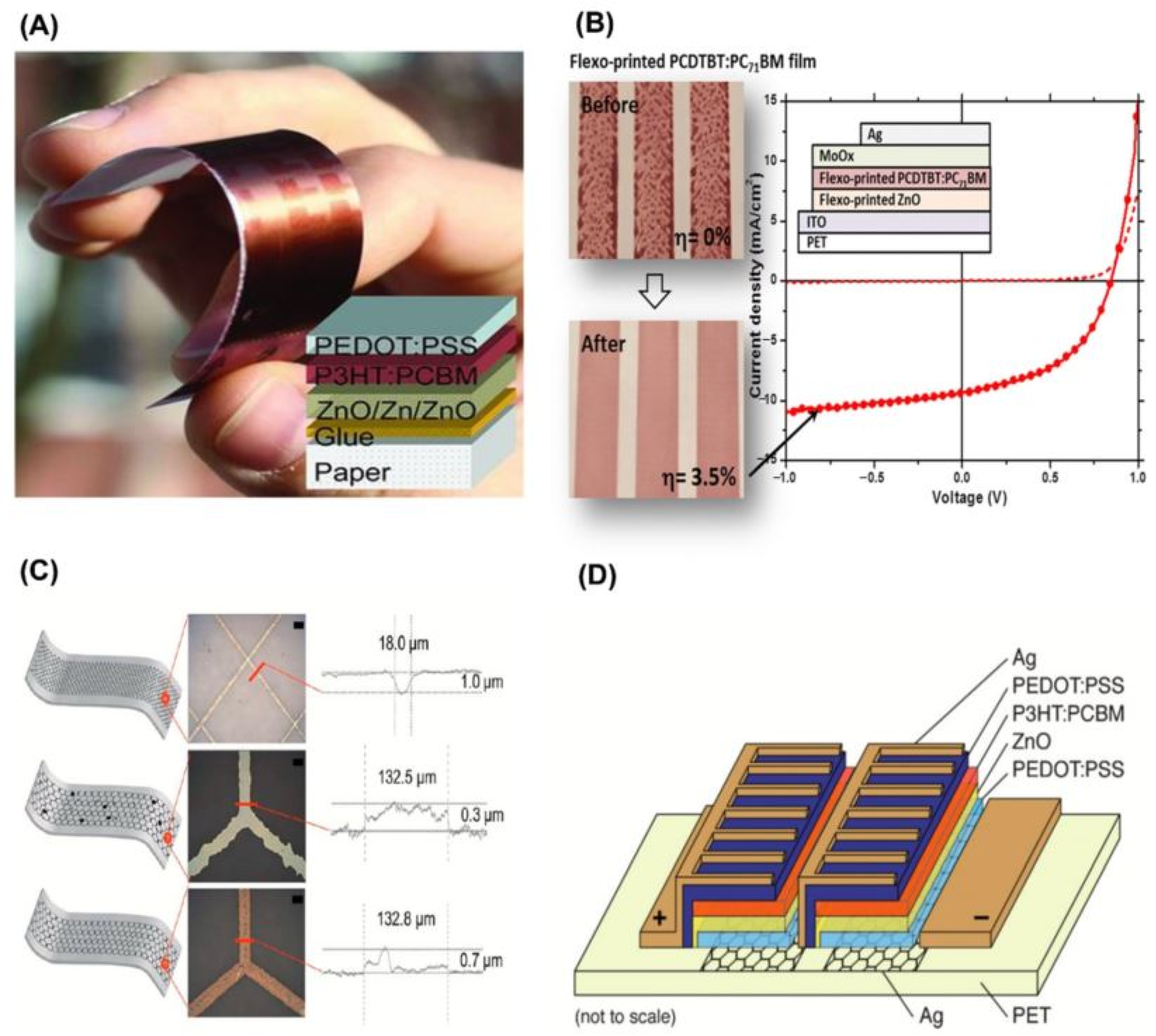
3. Polymer Solar Cell

Polymer solar cells (PSCs) have inherently scalable printing compared to silicon solar cells. The available literature indicates that PSCs are lightweight cells regardless of operational lifetime and ability to harvest low-cost energy at a high speed of production [47]. Furthermore, polymer solar cells have outstanding features compared to other solar cells, for instance, substrate flexibility, low-temperature processing, cost, and ease of manufacturing [48]. The main advantage associated with PSCs is the ability to produce power of about 10 kWp to attain 8.1 € Wp, while crystalline silicon solar cell produces 50 MWp at a similar cost [27].
PSCs can be integrated into flexible electronic module devices [49], such as a miniaturized reading lamp [50] and a small FM radio battery charger [51]. Frederik et al. believed that FPT with the assistance of other techniques may provide space to change the electronic module strategy. This may facilitate the manufacturing of PSCs, which have the unique feature of being able to charge a lithium-ion battery of a small LED-based pocket lamp with a thin outline and a rigid structure [27]. To charge a polymer lithium-ion battery through a blocking diode, they fabricated 5 mm wide lines of different materials (Zinc Oxide, Poly (3-Hexythiophene): [6,6]-Phenyl-C61-butyric acid methyl ester and [6,6]-Phenyl-C71-butyric acid methyl ester (P3HT:PCBM), Poly (3,4-ethylene dioxythiophene): Poly(styrenesulfonate) (PEDOT:PSS) and Silver) on an indium tin oxide-polyethylene terephthalate (ITO-PET) substrate (see Figure 4). It was reported that the best result was achieved for the P3HT:PCBM materials. Such materials obtained the best power conversion of 2.75% after 10 h of exposure to natural sunlight [27].
Despite these promises, PSC technology requires further expansion to gain a distinct share in the field of thin-film solar cells and to attract the desire for new areas of application. To serve this purpose, the following impediments must be remedied: (i) material costs, (ii) the stability of the hole-transporting layer, (iii) the deposition process of the functional active layer, (iv) substitution of the indium-tin-oxide layer, (v) formation speed, and (vi) manufacturing environmental concern [27].
Flexographic technical assistance proves its ability to manage and improve these impediments in many ways. Firstly, the major obstacle of photovoltaic high production and costs can be settled using an organic-based photovoltaic cell based on bulk heterojunctions (BHJs) of a polymer blended with fullerene [52]. Hübler et al. reported a novel photovoltaic design with economically feasible electrodes and free patterns. In their layer structure design, the photovoltaic cell comprises a paper substrate/Zn/ZnO/photovoltaic layer (blend of P3HT and PCBM.)/PEDOT: PSS, where the Zn and the PEDOT: PSS are the cathode and the anode, respectively. In the layered structure design, the hole-blocking layer is presented by a thin ZnO interlayer [53], which acts as an oxygen barrier and an optical spacer layer [54]. The ohmic nature of the Zn/ZnO interface and the converge value of the ZnO conduction band facilitate the efficient electron transfer at their interface [55,56,57]. The authors further explained that the interface between P3HT and ZnO functions as an effective dissociation region of photogenerated excitons besides the one that occurs in the photoactive layer. Moreover, Hübler et al. utilized three printing steps to fabricate the solar cell, including (i) cold-foil transfer printing of an oxidized Zn cathode on a glossy paper; (ii) gravure printing of the photoactive layer (P3HT:PCBM); and (iii) flexographic printing of the PEDOT: PSS anode. After the second step, the sample was placed in the oven to dry at under 130 °C for 5 min. Flexographic printing with a standard patterning plate and a speed of 0.5 ms−1 was used to apply the conducting and transparent anode (PEDOT:PSS) on top of the solar cell. A printed pattern of a flexible photovoltaic cell on paper is depicted in Figure 5A. The solar cell produced by A. Hübler et al. achieved promising power conversion efficiency (1.31%), fill factor (37%), open-circuit voltage (0.59 V), and short-circuit current density of 3.64 mA cm−2 [53].
In addition, organic bulk-heterojunction solar cells (OPV) have primarily concerned with the stability of the hole-transporting layer (HTL) materials. Research demonstrates that the use of vanadium alkoxide precursor for HTL layer printing carries the disadvantage of long curing [58,59,60]. In this context, Kololuoma and coworkers [61] formulated a stable vanadium oxide sol–gel process to modify flexographic ink to print hole-transporting layers for inverted organic solar cells. He utilized three approaches to achieve a high quality and stability of the ink by (i) controlling the amount of added water; (ii) decreasing the reactivity of the vanadium alkoxide using 2-methoxy ethanol as a bidental chelate-forming ligand; and (iii) regulating the hydrolysis rate and oxide formation using a coordinating additive [62,63]. A smooth and uniform HTL layer printed on the top of the light-harvesting layer facilitates solar cells to demonstrate power conversion efficiencies of 3.5–4.5% [61].
Nevertheless, the deposition process influences the performance of bulk-heterojunction solar cells by affecting the active layer morphology. To fabricate a large number of organic photovoltaics, high throughput processes help in harvesting a defect-free, homogenous, pinhole-free functional active layer with a particular thickness. In comparison to conventional methods, such as slot-die and gravure, FPT can achieve a high throughput of active layers. Salima et al. achieved outstanding results by optimizing the halftone pattern of the flexo plate, printing speed (6 m/min for homogenous active layers), drying process (50 °C for the 30 s), solvent ratio (to reduce pinhole formation), and uniformity. Eventually, they successfully printed an 80 nm thick active layer with smooth morphology (roughness of approximately 1 nm) on a flexible substrate using FPT. The photolytic cell device demonstrates an efficiency of 3.5% after using a reflective Ag electrode, as shown in Figure 5B [64].
Secondly, the flexographic printing of a smooth thin layer of indium tin oxide (ITO) faces challenges that may be related to the surface topography produced during the processing of succeeding layers [65]. In this regard, the front electrode of the semitransparent conductor in the polymer solar cell was replaced by the ITO with polymer-based material PEDOT:PSS (3,4 ethylene dioxythiophene: polystyrene sulfonate). However, the electrical conductivity of the PEDOT:PSS barely showed the imperative functions of large-area electrodes and high optical transmission. To overcome these issues, a combination of the PEDOT: PSS and highly conductive metallic grid were practiced and the results showed a smaller shadow loss of less than 20% [66,67,68]. Jong-Su et al. compared several (flexographic, embedded, and inkjet) printing techniques to form a silver grid structure in the solar cell based on water nanoparticle silver inks, as depicted in Figure 5C. They found that the raised topography by the flexo grid performs evenly well as the embedded grid and, on the contrary side, the raised topography of the inkjet grid leads to an optical shadow loss. Therefore, the flexographic technique exhibits the fastest processing of 25 m min−1 and the lowest silver consumption of 200 mg/m2 of the printed area. As a result of the real sun experiment, the power conversion efficiency (PCE) of the thermally imprinted, flexographic, and inkjet silver grids achieves 1.84%, 1.72%, and 0.79%, respectively, for (6 cm2) ITO-free polymer solar cell device area [69].
Thirdly, the manufacturing of a polymer solar cell module demands a suitable method with proper materials, environmental-friendly ink, satisfactory processing speed with a high degree of accuracy, and technical yield. Unlike flexographic printing, there are various printing methods applied to print the high-conducting metal back electrode in polymer solar cells through an evaporation processing of pure metal. However, this method carries some hitches including processing speed, processing equipment expenses, and direct operation. The screen-printing technique has been also used to print a highly conductive thick film of the back electrode; however, the drying period has an impact on the processing speed which requires a considerable amount of material. Furthermore, contact-free deposition, such as the inkjet method, faces nozzle clogging issues that affect the quality of printing and film deposition on the substrate. However, FPT can successfully be employed to print silver back electrodes for polymer solar cell modules based on the water-based silver ink process without a vacuum step; the full module is demonstrated in Figure 5D. As a result, the ink is positively transferred onto the polyethylene terephthalate (PET) substrate and deposited over the bottom silver grid for the sequential connection through the unoptimized rough surface of the PEDOT:PSS. A full-layer sheet resistance of 162 mΩ was noticed at a maximum speed of 10 m.min−1, which is comparable to the screen-printed silver electrode [70]. Table 2 displays a summary of the flexographic printing technique used for the manufacturing of polymer solar cells.

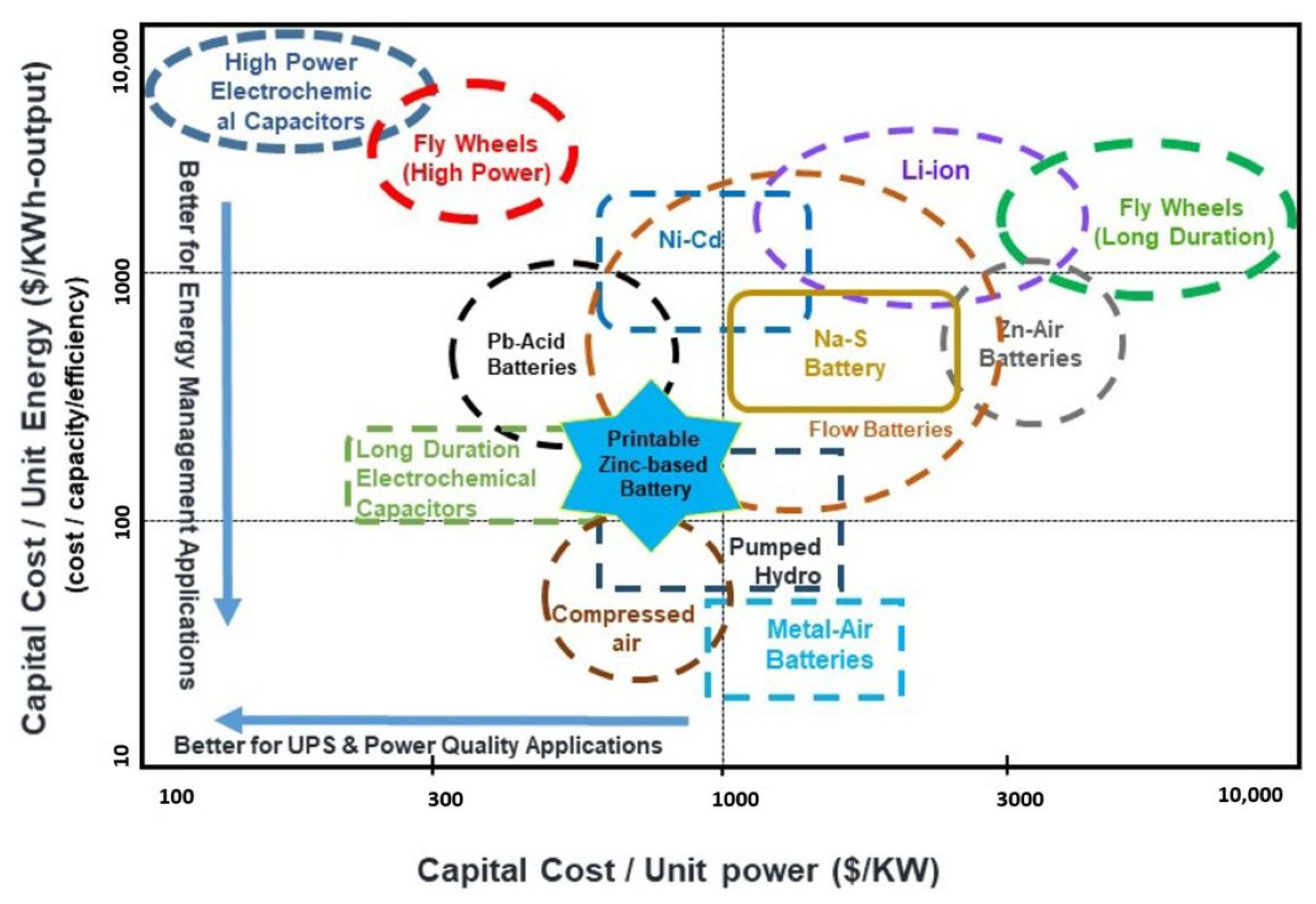
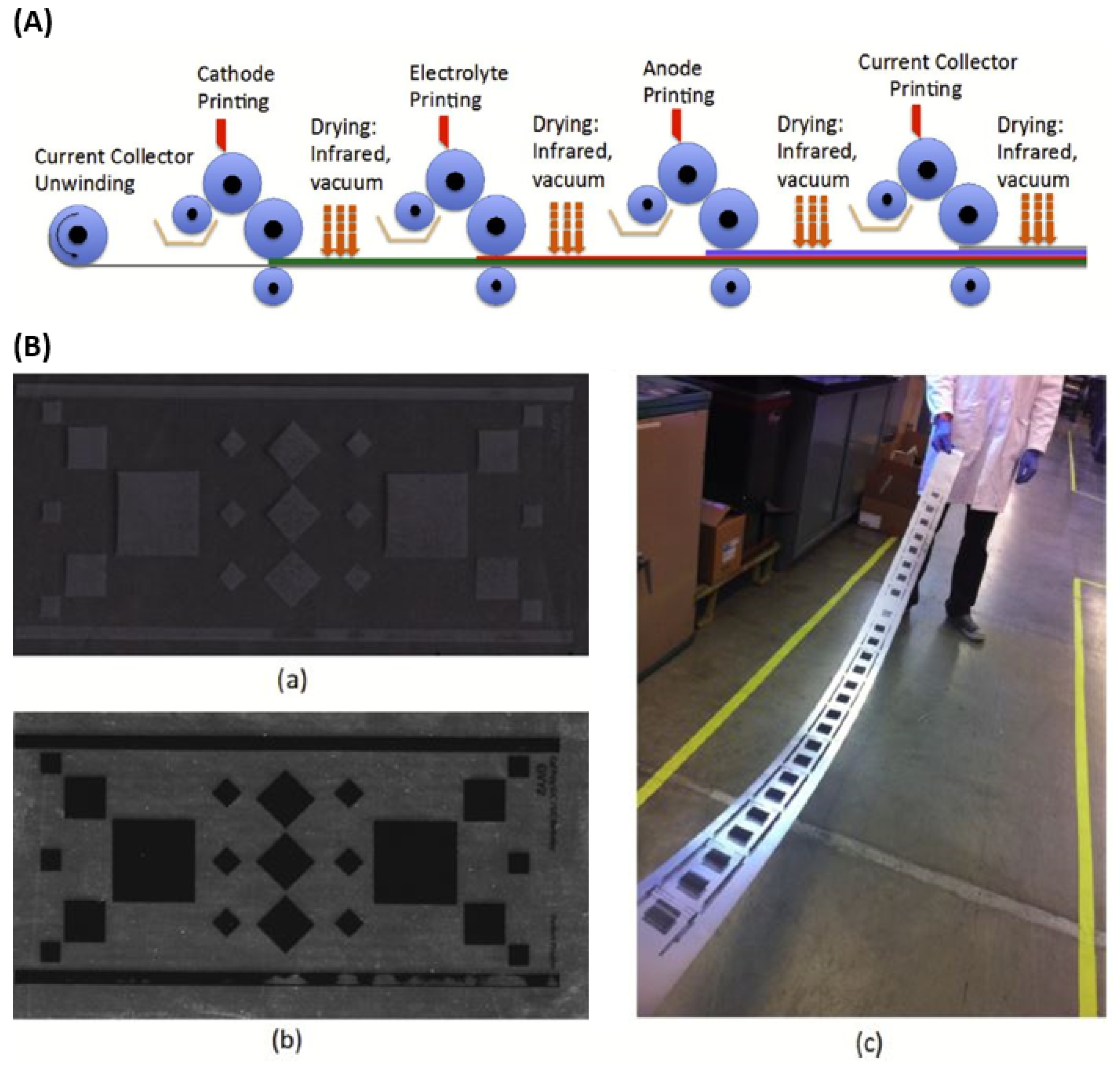
4. Energy Storage Application

Significant attention has been paid to energy storage recently [71], especially in the battery community, which has prompted the improvement of the chemistries of rechargeable zinc batteries. These improvements have been mainly inspired by their suitability, low toxicity, inherent safety, power density, high energy, portable handling, and low cost [72,73]. For instance, researchers have studied rechargeable batteries of nickel-zinc [74,75] silver-zinc [76], alkaline manganese dioxide (MnO2)-zinc [77,78], and zinc-air [79,80]. However, these battery chemistries face obstacles related to undesired shape changes, dendrite structure, and solubility of reaction products within the standard alkaline electrolyte, which leads to the weak rechargeability of the zinc electrode [81]. A typical solution for manufacturing large-format zinc-based batteries has been utilized by using FPT, which is also competitive with other energy storage grids in terms of exceptional performance, scalability in fabrication, utilization, and materials cost. Figure 6 illustrates the computation and comparison between this printing technique and other grid energy storage technologies based on the capital cost per unit energy and unit power, in which the assessment depends on the capital cost of flexographic manufacture and battery material, while the battery power cost counts on an average discharge rate of 0.1 °C (courtesy of ESA and Dr. James Evans). [82].
Flexographic printing is a fully scalable technology, which promises to produce long-life, safe, inexpensive, and flexible batteries. A reported study by Wang et al. used multi-station flexographic printing to manufacture a rechargeable zinc-based battery, as shown in Figure 7A. They developed a four-station flexographic printer, each of which is designed to print the cathode, the electrolyte, the anode, and the current collector in series, respectively. Furthermore, they developed and comprehensively analyzed a variety of MnO2 cathode inks based on these criteria (see Figure 7B). The fabricated batteries exhibited capacities ranging from mA-h (micro-batteries) to A-h (grid-scale batteries) [26].

5. Conclusions

The flexographic printing technique may be concluded as an attractive technology for the manufacturing of a variety of energy-harvesting cells and energy-storing devices at an affordable cost. Thereby, it is briskly replacing the classical printing technologies to produce energy harvesting/storage devices for future medical, automobile, and aircraft markets. In recent years, substantial attention has focused on how to enhance the efficiency of the flexographic printing technique and it has proven its potential in achieving mass production at a reasonable cost. This article provides a comprehensive picture of the progress of flexographic printing fabrication of solar cells and batteries for contemporary and future markets. It has compared flexographic printing to contemporary printing technologies and meticulously documented the advantages and disadvantages from the perspective of cost-effective, flexible solar cells and batteries. Whilst the flexographic printing technique has numerous benefits, it is attributed with certain challenges, including reproducibility of printing materials, throughput, and supreme quality of the final product. Despite these disadvantages, the window is still open for exploring new ways and technology of development and improvement. It is highly anticipated that the printing industry will soon implement a flexographic technique for the fabrication of energy harvesting/storage devices owing to its promised advantages.

Funding

This research received no external funding.

Data Availability Statement

The data presented in this study are available on request from the corresponding author.

Conflicts of Interest

The authors declare no conflict of interest.

References

  1. Bagher, A.M.; Vahid, M.M.A.; Mohsen, M. Types of solar cells and application. Am. J. Opt. Photonics 2015, 3, 94–113. [Google Scholar] [CrossRef] [Green Version]
  2. Platzer, M.D. US Solar Photovoltaic Manufacturing: Industry Trends, Global Competition, Federal Support; Congressional Research Service; Library of Congress: Washington, DC, USA, 2012. [Google Scholar]
  3. Sharma, S.; Jain, K.K.; Sharma, A. Solar cells: In research and applications—A review. Mater. Sci. Appl. 2015, 6, 1145. [Google Scholar] [CrossRef] [Green Version]
  4. Archer, M.D.; Green, M.A. (Eds.) . Clean Electricity from Photovoltaics; World Scientific: Singapore, 2014; Volume 4. [Google Scholar]
  5. Mahesh, D.; Rajesh, J. TiO2 microstructure, fabrication of thin film solar cells and introduction to dye sensitized solar cells. Res. J. Recent Sci. 2012, 2, 25–29. [Google Scholar]
  6. Li, G.; Zhu, R.; Yang, Y. Polymer solar cells. Nat. Photonics 2012, 6, 153–161. [Google Scholar] [CrossRef]
  7. Zhang, L.; Jia, T.; Pan, L.; Wu, B.; Wang, Z.; Gao, K.; Cao, Y. 15.4% Efficiency all-polymer solar cells. Sci. China Chem. 2021, 64, 408–412. [Google Scholar] [CrossRef]
  8. Ahn, N.; Son, D.Y.; Jang, I.H.; Kang, S.M.; Choi, M.; Park, N.G. Highly reproducible perovskite solar cells with average efficiency of 18.3% and best efficiency of 19.7% fabricated via Lewis base adduct of lead (II) iodide. J. Am. Chem. Soc. 2015, 137, 8696–8699. [Google Scholar] [CrossRef]
  9. Zhang, Y.; Yi, H.; Iraqi, A.; Kingsley, J.; Buckley, A.; Wang, T.; Lidzey, D.G. Comparative indoor and outdoor stability measurements of polymer based solar cells. Sci. Rep. 2017, 7, 1305. [Google Scholar] [CrossRef] [Green Version]
  10. Li, B.; Wang, L.; Kang, B.; Wang, P.; Qiu, Y. Review of recent progress in solid-state dye-sensitized solar cells. Sol. Energy Mater. Sol. Cells 2006, 90, 549–573. [Google Scholar] [CrossRef]
  11. Graetzel, M.; Janssen, R.A.; Mitzi, D.B.; Sargent, E.H. Materials interface engineering for solution-processed photovoltaics. Nature 2012, 488, 304–312. [Google Scholar] [CrossRef] [PubMed]
  12. Suhaimi, S.; Shahimin, M.M.; Alahmed, Z.A.; Chyský, J.; Reshak, A.H. Materials for enhanced dye-sensitized solar cell performance: Electrochemical application. Int. J. Electrochem. Sci. 2015, 10, 2859–2871. [Google Scholar]
  13. Liang, M.; Xu, W.; Cai, F.; Chen, P.; Peng, B.; Chen, J.; Li, Z. New triphenylamine-based organic dyes for efficient dye-sensitized solar cells. J. Phys. Chem. C 2007, 111, 4465–4472. [Google Scholar] [CrossRef]
  14. Shah, D.K. A Study on the Surface Texturing and Antireflection Coating with Nanomaterials for Crystalline Silicon Solar Cell. Master’s Thesis, Jeonbuk National University, Jeonju, Republic of Korea, 2022. [Google Scholar]
  15. Ebong, A.; Chen, N. Metallization of crystalline silicon solar cells: A review. In High Capacity Optical Networks and Emerging/Enabling Technologies; IEEE: New York, NY, USA, 2012; pp. 102–109. [Google Scholar]
  16. Mayer, A.; Scully, S.; Hardin, B.; Rowell, M.; McGehee, M. Polymer-based solar cells. Mater. Today 2007, 10, 28. [Google Scholar] [CrossRef]
  17. Sampaio, P.G.V.; Gonzalez, M.O.A.; de Oliveira Ferreira, P.; da Cunha Jacome Vidal, P.; Pereira, J.P.P.; Ferreira, H.R.; Oprime, P.C. Overview of printing and coating techniques in the production of organic photovoltaic cells. Int. J. Energy Res. 2020, 44, 9912–9931. [Google Scholar] [CrossRef]
  18. Brabec, C.J.; Shaheen, S.E.; Winder, C.; Sariciftci, N.S.; Denk, P. Effect of LiF/metal electrodes on the performance of plastic solar cells. Appl. Phys. Lett. 2002, 80, 1288–1290. [Google Scholar] [CrossRef]
  19. Ur Rehman, A.; Lee, S.H. Crystalline silicon solar cells with nickel/copper contacts. In Solar Cells-New Approaches and Reviews; InTech Open: Rijeka, Croatia, 2015. [Google Scholar]
  20. Brunetti, F.; Operamolla, A.; Castro-Hermosa, S.; Lucarelli, G.; Manca, V.; Farinola, G.M.; Brown, T.M. Printed solar cells and energy storage devices on paper substrates. Adv. Funct. Mater. 2019, 29, 1806798. [Google Scholar] [CrossRef] [Green Version]
  21. Huddy, J.E.; Ye, Y.; Scheideler, W.J. Precursor Ink Design for Scalable Fabrication of Perovskite Solar Cells via High-Speed Flexography. In Proceedings of the 2022 IEEE 49th Photovoltaics Specialists Conference (PVSC), San Juan, Puerto Rico, 11–16 June 2022; p. 0028. [Google Scholar]
  22. Samantaray, N.; Parida, B.; Soga, T.; Sharma, A.; Kapoor, A.; Najar, A.; Singh, A. Recent Development and Directions in Printed Perovskite Solar Cells. Phys. Status Solidi 2022, 219, 2100629. [Google Scholar] [CrossRef]
  23. Tomašegović, T.; Mahović Poljaček, S.; Strižić Jakovljević, M.; Urbas, R. Effect of the common solvents on UV-modified photopolymer and EPDM flexographic printing plates and printed ink films. Coatings 2020, 10, 136. [Google Scholar] [CrossRef] [Green Version]
  24. Ljevak, I.; Bilalli, A. Correlation between Ink Thickness and" Shrink Sleeve" Flexographic Print Quality at a Stable Friction Coefficient. Teh. Glas. 2021, 15, 366–370. [Google Scholar]
  25. Hösel, M.; Krebs, F.C. Large-scale roll-to-roll photonic sintering of flexo printed silver nanoparticle electrodes. J. Mater. Chem. 2012, 22, 15683–15688. [Google Scholar] [CrossRef]
  26. Wang, Z.; Winslow, R.; Madan, D.; Wright, P.K.; Evans, J.W.; Keif, M.; Rong, X. Development of MnO2 cathode inks for flexographically printed rechargeable zinc-based battery. J. Power Sources 2014, 268, 246–254. [Google Scholar] [CrossRef] [Green Version]
  27. Krebs, F.C.; Fyenbo, J.; Jørgensen, M. Product integration of compact roll-to-roll processed polymer solar cell modules: Methods and manufacture using flexographic printing, slot-die coating and rotary screen printing. J. Mater. Chem. 2010, 20, 8994–9001. [Google Scholar] [CrossRef]
  28. Lorenz, A.; Senne, A.; Rohde, J.; Kroh, S.; Wittenberg, M.; Krüger, K.; Biro, D. Evaluation of flexographic printing technology for multi-busbar solar cells. Energy Procedia 2015, 67, 126–137. [Google Scholar] [CrossRef]
  29. Assaifan, A.K.; Al Habis, N.; Ahmad, I.; Alshehri, N.A.; Alharbi, H.F. Scaling-up medical technologies using flexographic printing. Talanta 2020, 219, 121236. [Google Scholar] [CrossRef] [PubMed]
  30. Zhong, Z.W.; Ee, J.H.; Chen, S.H.; Shan, X.C. Parametric investigation of flexographic printing processes for R2R printed electronics. Mater. Manuf. Process. 2020, 35, 564–571. [Google Scholar] [CrossRef]
  31. Lorenz, A.; Klawitter, M.; Linse, M.; Tepner, S.; Röth, J.; Wirth, N.; Clement, F. The project» Rock-Star «: The evolution of rotary printing for solar cell metallization. In AIP Conference Proceedings; AIP Publishing LLC: Long Island, NY, USA, 2021; Volume 2367, p. 020008. [Google Scholar]
  32. Lorenz, A.; Kalio, A.; Hofmeister, G.T.; Nold, S.; Kraft, A.; Bartsch, J.; Biro, D. Flexographic printing–high throughput technology for fine line seed layer printing on silicon solar cells. In Proceedings of the 28th European Photovoltaic Solar Energy Conference and Exhibition, EUPVSEC, Paris, France, 30 September–4 October 2013; Volume 30, pp. 1017–1023. [Google Scholar]
  33. Thibert, S.; Jourdan, J.; Bechevet, B.; Mialon, S.; Beneventi, D.; Chaussy, D.; Reverdy-Bruas, N. Flexographic Process for Front Side Metallization of Silicon Solar Cell. In Proceedings of the 28th European Photovoltaic Solar Energy Conference and Exhibition, EUPVSEC, Paris, France, 30 September–4 October 2013; Volume 30, pp. 1013–1016. [Google Scholar]
  34. Wegener, M.; Spiehl, D.; Sauer, H.M.; Mikschl, F.; Liu, X.; Kölpin, N.; Schmidt, M.; Jank, M.P.; Dörsam, E.; Roosen, A. Flexographic printing of nanoparticulate tin-doped indium oxide inks on PET foils and glass substrates. J. Mater. Sci. 2016, 51, 4588–4600. [Google Scholar] [CrossRef]
  35. Hwang, M.; Kim, S.; Lee, K.; Moon, I.; Lim, J.; Lee, J.; Cho, E. Fine and high aspect ratio front electrode formation for improving efficiency of the multicristalline silicon solar cells. In Proceedings of the 25th European Photovoltaic Solar Energy Conference, Valencia, Spain, 6–10 September 2010; pp. 1792–1795. [Google Scholar]
  36. Frey, M.; Clement, F.; Dilfer, S.; Erath, D.; Biro, D. Front-side metalization by means of flexographic printing. Energy Procedia 2011, 8, 581–586. [Google Scholar] [CrossRef]
  37. Thibert, S.; Chaussy, D.; Beneventi, D.; Reverdy-Bruas, N.; Jourdan, J.; Bechevet, B.; Mialon, S. Silver ink experiments for silicon solar cell metallization by flexographic process. In Proceedings of the 2012 38th IEEE Photovoltaic Specialists Conference, Austin, TX, USA, 3–8 June 2012; pp. 002266–002270. [Google Scholar]
  38. Thibert, S.; Jourdan, J.; Bechevet, B.; Mialon, S.; Chaussy, D.; Reverdy-Bruas, N.; Beneventi, D. Study of the high throughput flexographic process for silicon solar cell metallisation. Prog. Photovolt. Res. Appl. 2016, 24, 240–252. [Google Scholar] [CrossRef]
  39. Mette, A. New concepts for front side metallization of industrial silicon solar cells. Doctoral Thesis, Albert-Ludwigs-Universität, Freiburg im Breisgau, Germany, 2007. [Google Scholar]
  40. Lorenz, A.; Kraft, A.; Gredy, C.; Filipovic, A.; Binder, S.; Krüger, K.; Bartsch, J.; Clement, F.; Biro, D.; Preu, R.; et al. Comprehensive Comparison of Different Fine Line Printing Technologies Adressing the Seed and Plate Approach with Ni-Cu-Plating. Proc. 30th EUPVSEC 2015, 732–736. [Google Scholar]
  41. Kalio, A.; Richter, A.; Hörteis, M.; Glunz, S.W. Metallization of n-type silicon solar cells using fine line printing techniques. Energy Procedia 2011, 8, 571–576. [Google Scholar] [CrossRef]
  42. Kray, D.; Aleman, M.; Fell, A.; Hopman, S.; Mayer, K.; Mesec, M.; Richerzhagen, B. Laser-doped silicon solar cells by laser chemical processing (LCP) exceeding 20% efficiency. In Proceedings of the 2008 33rd IEEE Photovoltaic Specialists Conference, San Diego, CA, USA, 11–16 May 2008; pp. 1–3. [Google Scholar]
  43. Tous, L.; Lerat, J.F.; Emeraud, T.; Negru, R.; Huet, K.; Uruena, A.; Mertens, R. Nickel silicide contacts formed by excimer laser annealing for high efficiency solar cells. Prog. Photovolt. Res. Appl. 2013, 21, 267–275. [Google Scholar] [CrossRef]
  44. Lorenz, A.; Gredy, C.; Beyer, S.; Yao, Y.; Papet, P.; Ufheil, J.; Clement, F. Flexographic printing–towards an advanced front side metallization approach with high throughput and low silver consumption. Sol. Energy Mater. Sol. Cells 2016, 157, 550–557. [Google Scholar] [CrossRef]
  45. Mette, A.; Richter, P.L.; Hörteis, M.; Glunz, S.W. Metal aerosol jet printing for solar cell metallization. Prog. Photovolt. Res. Appl. 2007, 15, 621–627. [Google Scholar] [CrossRef]
  46. Lorenz, A.; Gredy, C.; Senne, A.; Beyer, S.; Yao, Y.; Papet, P.; Clement, F. Flexoprinted busbarless solar cells for multi-wire interconnection. Energy Procedia 2016, 98, 46–60. [Google Scholar] [CrossRef]
  47. Nuhash, M.M.; Alam, I.; Islam, A.N.U. Manufacturing Processes of Solution-processed Organic Solar cells and Recent Advances. In Proceedings of the Third International Conference on Industrial & Mechanical Engineering and Operations Management (IMEOM), Dhaka, Bangladesh, 26–27 December 2020; p. 217. [Google Scholar]
  48. Søndergaard, R.; Hösel, M.; Angmo, D.; Larsen-Olsen, T.T.; Krebs, F.C. Roll-to-roll fabrication of polymer solar cells. Mater. Today 2012, 15, 36–49. [Google Scholar] [CrossRef]
  49. Zhang, Y.Z.; Wang, Y.; Cheng, T.; Yao, L.Q.; Li, X.; Lai, W.Y.; Huang, W. Printed supercapacitors: Materials, printing and applications. Chem. Soc. Rev. 2019, 48, 3229–3264. [Google Scholar] [CrossRef] [PubMed]
  50. Krebs, F.C.; Nielsen, T.D.; Fyenbo, J.; Wadstrøm, M.; Pedersen, M.S. Manufacture, integration and demonstration of polymer solar cells in a lamp for the “Lighting Africa” initiative. Energy Environ. Sci. 2010, 3, 512–525. [Google Scholar] [CrossRef]
  51. Krebs, F.C.; Jørgensen, M.; Norrman, K.; Hagemann, O.; Alstrup, J.; Nielsen, T.D.; Kristensen, J. A complete process for production of flexible large area polymer solar cells entirely using screen printing—First public demonstration. Sol. Energy Mater. Sol. Cells 2009, 93, 422–441. [Google Scholar] [CrossRef]
  52. Xue, P.; Cheng, P.; Han, R.P.; Zhan, X. Printing fabrication of large-area non-fullerene organic solar cells. Mater. Horiz. 2022, 9, 194–219. [Google Scholar] [CrossRef]
  53. Hübler, A.; Trnovec, B.; Zillger, T.; Ali, M.; Wetzold, N.; Mingebach, M.; Dyakonov, V. Printed paper photovoltaic cells. Adv. Energy Mater. 2011, 1, 1018–1022. [Google Scholar] [CrossRef]
  54. Yip, H.L.; Hau, S.K.; Jen, A.K.Y. Interface engineering of stable, efficient polymer solar cells. Sol. Altern. Energy 2009. [CrossRef]
  55. Hsueh, T.J.; Hsu, C.L. Fabrication of gas sensing devices with ZnO nanostructure by the low-temperature oxidation of zinc particles. Sens. Actuators B Chem. 2008, 131, 572–576. [Google Scholar] [CrossRef]
  56. Radhakrishnan, S.; Saini, D.R. Electrical properties of polyester elastomer composites containing metallic fillers. J. Mater. Sci. 1991, 26, 5950–5956. [Google Scholar] [CrossRef]
  57. Oosterhout, S.D.; Wienk, M.M.; Van Bavel, S.S.; Thiedmann, R.; Koster, L.J.A.; Gilot, J.; Janssen, R.A. The effect of three-dimensional morphology on the efficiency of hybrid polymer solar cells. Nat. Mater. 2009, 8, 818–824. [Google Scholar] [CrossRef] [PubMed]
  58. Chen, C.P.; Chen, Y.D.; Chuang, S.C. High-performance and highly durable inverted organic photovoltaics embedding solution-processable vanadium oxides as an interfacial hole-transporting layer. Adv. Mater. 2011, 23, 3859–3863. [Google Scholar] [CrossRef] [PubMed]
  59. Zilberberg, K.; Trost, S.; Meyer, J.; Kahn, A.; Behrendt, A.; Lützenkirchen-Hecht, D.; Frahm, R.; Riedl, T. Inverted organic solar cells with sol–gel processed high work-function vanadium oxide hole-extraction layers. Adv. Funct. Mater. 2011, 21, 4776–4783. [Google Scholar] [CrossRef]
  60. Hajzeri, M.; Vuk, A.Š.; Perše, L.S.; Čolović, M.; Herbig, B.; Posset, U.; Orel, B. Sol–gel vanadium oxide thin films for a flexible electronically conductive polymeric substrate. Sol. Energy Mater. Sol. Cells 2012, 99, 62–72. [Google Scholar] [CrossRef]
  61. Kololuoma, T.; Lu, J.; Alem, S.; Graddage, N.; Movileanu, R.; Moisa, S.; Tao, Y. Flexo printed sol-gel derived vanadium oxide films as an interfacial hole-transporting layer for organic solar cells. In Oxide-Based Materials and Devices VI.; International Society for Optics and Photonics: Belligham, WA, USA, 2015; Volume 9364, p. 93640K. [Google Scholar]
  62. Zilberberg, K.; Trost, S.; Schmidt, H.; Riedl, T. Solution processed vanadium pentoxide as charge extraction layer for organic solar cells. Adv. Energy Mater. 2011, 1, 377–381. [Google Scholar] [CrossRef]
  63. Huang, J.S.; Chou, C.Y.; Liu, M.Y.; Tsai, K.H.; Lin, W.H.; Lin, C.F. Solution-processed vanadium oxide as an anode interlayer for inverted polymer solar cells hybridized with ZnO nanorods. Org. Electron. 2009, 10, 1060–1065. [Google Scholar] [CrossRef]
  64. Alem, S.; Graddage, N.; Lu, J.; Kololuoma, T.; Movileanu, R.; Tao, Y. Flexographic printing of polycarbazole-based inverted solar cells. Org. Electron. 2018, 52, 146–152. [Google Scholar] [CrossRef]
  65. Castro, M.F.; Mazzolini, E.; Sondergaard, R.R.; Espindola-Rodriguez, M.; Andreasen, J.W. Flexible ITO-free roll-processed large-area nonfullerene organic solar cells based on P3HT: O-IDTBR. Phys. Rev. Appl. 2020, 14, 034067. [Google Scholar] [CrossRef]
  66. Galagan, Y.; Zimmermann, B.; Coenen, E.W.; Jørgensen, M.; Tanenbaum, D.M.; Krebs, F.C.; Andriessen, R. Current Collecting Grids for ITO-Free Solar Cells. Adv. Energy Mater. 2012, 2, 103–110. [Google Scholar] [CrossRef]
  67. Galagan, Y.; de Vries, I.G.; Langen, A.P.; Andriessen, R.; Verhees, W.J.; Veenstra, S.C.; Kroon, J.M. Technology development for roll-to-roll production of organic photovoltaics. Chem. Eng. Process. Process Intensif. 2011, 50, 454–461. [Google Scholar] [CrossRef] [Green Version]
  68. Galagan, Y.; Coenen, E.W.; Sabik, S.; Gorter, H.H.; Barink, M.; Veenstra, S.C.; Blom, P.W. Evaluation of ink-jet printed current collecting grids and busbars for ITO-free organic solar cells. Sol. Energy Mater. Sol. Cells 2012, 104, 32–38. [Google Scholar] [CrossRef] [Green Version]
  69. Yu, J.S.; Kim, I.; Kim, J.S.; Jo, J.; Larsen-Olsen, T.T.; Søndergaard, R.R.; Krebs, F.C. Silver front electrode grids for ITO-free all printed polymer solar cells with embedded and raised topographies, prepared by thermal imprint, flexographic and inkjet roll-to-roll processes. Nanoscale 2012, 4, 6032–6040. [Google Scholar] [CrossRef]
  70. Hösel, M.; Søndergaard, R.R.; Angmo, D.; Krebs, F.C. Comparison of Fast Roll-to-Roll Flexographic, Inkjet, Flatbed, and Rotary Screen Printing of Metal Back Electrodes for Polymer Solar Cells. Adv. Eng. Mater. 2013, 15, 995–1001. [Google Scholar] [CrossRef]
  71. Ahn, D.B.; Lee, S.S.; Lee, K.H.; Kim, J.H.; Lee, J.W.; Lee, S.Y. Form factor-free, printed power sources. Energy Storage Mater. 2020, 29, 92–112. [Google Scholar] [CrossRef]
  72. Karpinski, A.P.; Makovetski, B.; Russell, S.J.; Serenyi, J.R.; Williams, D.C. Silver–zinc: Status of technology and applications. J. Power Sources 1999, 80, 53–60. [Google Scholar] [CrossRef]
  73. Ho, C.C.; Evans, J.W.; Wright, P.K. Direct write dispenser printing of a zinc microbattery with an ionic liquid gel electrolyte. J. Micromechanics Microengineering 2010, 20, 1040. [Google Scholar] [CrossRef]
  74. Humble, P.H.; Harb, J.N.; LaFollette, R. Microscopic nickel-zinc batteries for use in autonomous microsystems. J. Electrochem. Soc. 2001, 148, A1357. [Google Scholar] [CrossRef]
  75. Zhang, L.; Huang, H.; Zhang, W.K.; Gan, Y.P.; Wang, C.T. Effects of conductive ceramic on the electrochemical performance of ZnO for Ni/Zn rechargeable battery. Electrochim. Acta 2008, 53, 5386–5390. [Google Scholar] [CrossRef]
  76. Higgins, R.L.; Erisman, L.R. Applications of the Lithium-Carbon Mono-Fluoride Battery. In Proceedings of the 28th Power Sources Symposium, Atlantic City, NJ, USA, 12–15 June 1978; pp. 208–210. [Google Scholar]
  77. Xu, C.; Du, H.; Li, B.; Kang, F.; Zeng, Y. Reversible insertion properties of zinc ion into manganese dioxide and its application for energy storage. Electrochem. Solid State Lett. 2009, 12, A61. [Google Scholar] [CrossRef]
  78. Kordesh, K.; Weissenbacher, M. Rechargeable alkaline manganese dioxide/zinc batteries. J. Power Sources 1994, 51, 61–78. [Google Scholar] [CrossRef]
  79. Ross, P.N., Jr. Zinc Electrode and Rechargeable Zinc-Air Battery; (No. US 4842963); Lawrence Berkeley National Lab. (LBNL): Berkeley, CA, USA, 1989. [Google Scholar]
  80. Müller, S.; Holzer, F.; Haas, O. Optimized zinc electrode for the rechargeable zinc–air battery. J. Appl. Electrochem. 1998, 28, 895–898. [Google Scholar] [CrossRef]
  81. McLarnon, F.R.; Cairns, E.J. The secondary alkaline zinc electrode. J. Electrochem. Soc. 1991, 138, 645. [Google Scholar] [CrossRef]
  82. Wang, Z. Flexographically printed rechargeable zinc-based battery for grid energy storage. Doctoral Thesis, UC Berkeley, Berkeley, CA, USA, 2013. [Google Scholar]
Figure 1. Schematic of a flexographic printing platform for the metallization of silicon solar cells. Ref. [28] Copyright 2015.
Energies 16 00869 g001
Figure 2. (A) Microscopic views for the comparison of three representative lines printed with paste A0 (upper) and ink A5 (lower). Reproduced with permission. Ref. [36] Copyright 2011. (B) Overview of the metallization results before (a) and after (be) the seed layer thickening by Ag-LIP. Reproduced with permission. Ref. [38] Copyright 2015. John Wiley and Sons. (C) Comparison of lines printed in the same conditions with different inks and anilox rolls. For each case, the line width and the line metallized area are reported. Reproduced with permission. Ref. [38] Copyright 2015. John Wiley and Sons.
Energies 16 00869 g002
Figure 3. (A) Fabricated mini-module using two flexo-printed solar cells with SmartWire interconnection. Reproduced with permission. Ref. [44] Copyright 2016. Elsevier. (B) Printing pressure investigation: a. First printing steps on Prescale film, and b. second printing steps on Si wafer using Ag-ink. Reproduced with permission. Ref. [46] Copyright 2016. Elsevier. (C) a. Experimental anilox roll featuring three differently engraved band sections with various dip volumes and line screenings. (D) Flexo-double-printed contact finger (width Wf = 33 μm). Reproduced with permission. Ref. [28] Copyright 2015. Elsevier.
Energies 16 00869 g003
Figure 4. A roll of the printed modules shows how two parallel sets of modules are prepared simultaneously. The zoom-in view shows the layer stack which is PET-ITO-ZnO-P3HT: PCBM-PEDOT: PSS-printed silver. The device stack is encapsulated using roll-to-roll lamination post-production. Reproduced with permission. Ref. [27] Copyright 2010. Royal Society of Chemistry.
Energies 16 00869 g004
Figure 5. (A) Photograph of the printed paper photovoltaic cell. Reproduced with permission. Ref. [53] Copyright 2011. John Wiley and Sons. (B) J-V characteristics in dark (dashed line) and under AM1.5 illumination of 100 mW/cm2 (circles). The inset illustrates the device structure. Reproduced with permission. Ref. [64] Copyright 2018. Elsevier. (C) Schematic illustrations of the different grid structures ( ~ 5 cm × 1 cm) along with optical confocal micrographs (scale bar is 100 mm) and traces across the grid lines showing the typical width and height (from the confocal micrograph). The thermally imprinted grid with Ag filling (top). Inkjet is shown (middle) with an illustration of the occasional presence of misfired ink droplets and the irregular structure of the grid lines, compared to the more regular flexographically printed grids (bottom). Reproduced with permission. Ref. [69] Copyright 2012. Royal Society of Chemistry. (D) Illustration of the fully R2R processed solar cell stack comprising the following materials: silver Ag, PEDOT:PSS, zinc oxide (ZnO), and P3HT:phenyl-C61-butyric acid methyl ester (P3HT:PCBM). The last Ag back electrode is printed using four different techniques. Reproduced with permission. Ref. [70] Copyright 2013. John Wiley and Sons.
Energies 16 00869 g005
Figure 6. Comparison between roll-to-roll printable zinc-based battery with different energy storage technologies in both capital cost per unit power and unit energy.
Energies 16 00869 g006
Figure 7. (A) The proposed multi-station flexographic printing process for large-scale battery production. (B) Significant improvement in printing quality on stainless steel foils by using cathode slurry inks with different polymeric binding solutions: (a). Printed films from MnO2 cathode ink formulations with CMC/SBR binder; (b). Improved printed films from cathode ink formulations with PSBR binder; (c). Five continuous printed PSBR cathode films on a piece of stainless-steel foil. Reproduced with permission. Ref. [26] Copyright 2014. Elsevier.
Energies 16 00869 g007
Table 1. Summary of flexographic printing technique on silicon solar cells.
ApplicationSubstrateInkResultReference
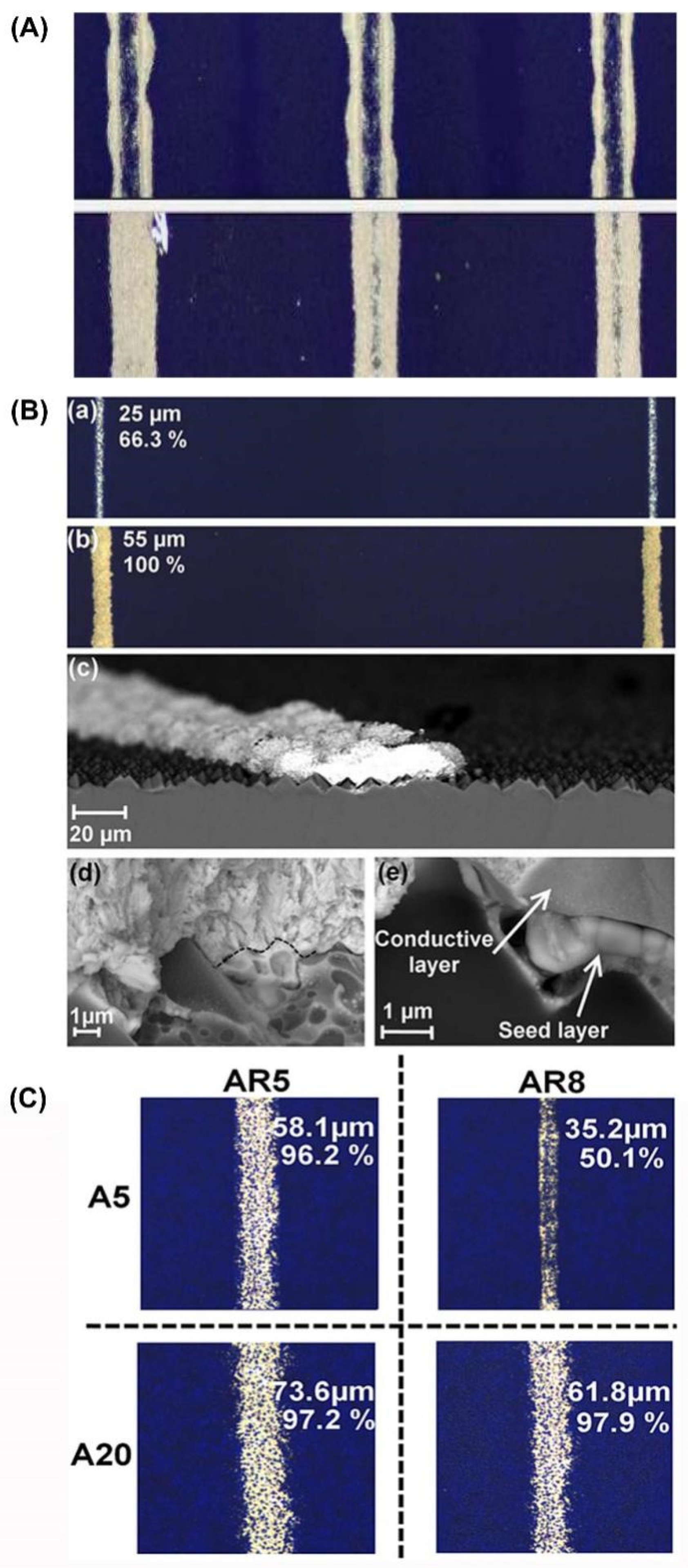
Using rheology characterization to study viscoelastic properties of a diluted screen-printing silver paste and to adapt such a paste to the flexographic printing process for depositing a seed layer.Monocrystalline silicon wafer after alkaline texturization(A0) Screen-printing silver paste ink containing 5, 7, 10, 15, and 20 wt% of the solventDeposit 30 μm in the width of the silver seed layer[37]
Print fine lines on the front-side metallization of silicon solar cells.P-type, textured Cz-Si
(Czrochalski-grown silicon)
Silver paste A with particle size ranging between 0.5 and 1 μm, and is diluted by 5, 10, 15, and 20 wt% of 2-(2-butoxyethoxy) ethanol to formulate A5, A10, A15, and A20.Encouraging 17.9% efficiency on Cz-Si solar cell[38]
Fabrication of the 1st busbarless solar cell with flexo-printed front-side metallization.Wafer material of Cz-Si p-type solar cell up to anti-reflection coating (precursors) with an edge length of 156 mmTwo types of silver-based inks (Ag-inks).
Ink A: aerosol jet optimization ink.
Ink B: diluted screen-printing Ag-paste
Achieving an average conversion efficiency of η = 19.0 % [44]
Printing of the front-side metallization of busbarless Al BSF solar cells with multi-wire interconnection.Silicon wafer
p-type Cz-Si precursors.
Silver ink (Ag-ink)Achieving an average conversion efficiency of η = 19.0 % [46]
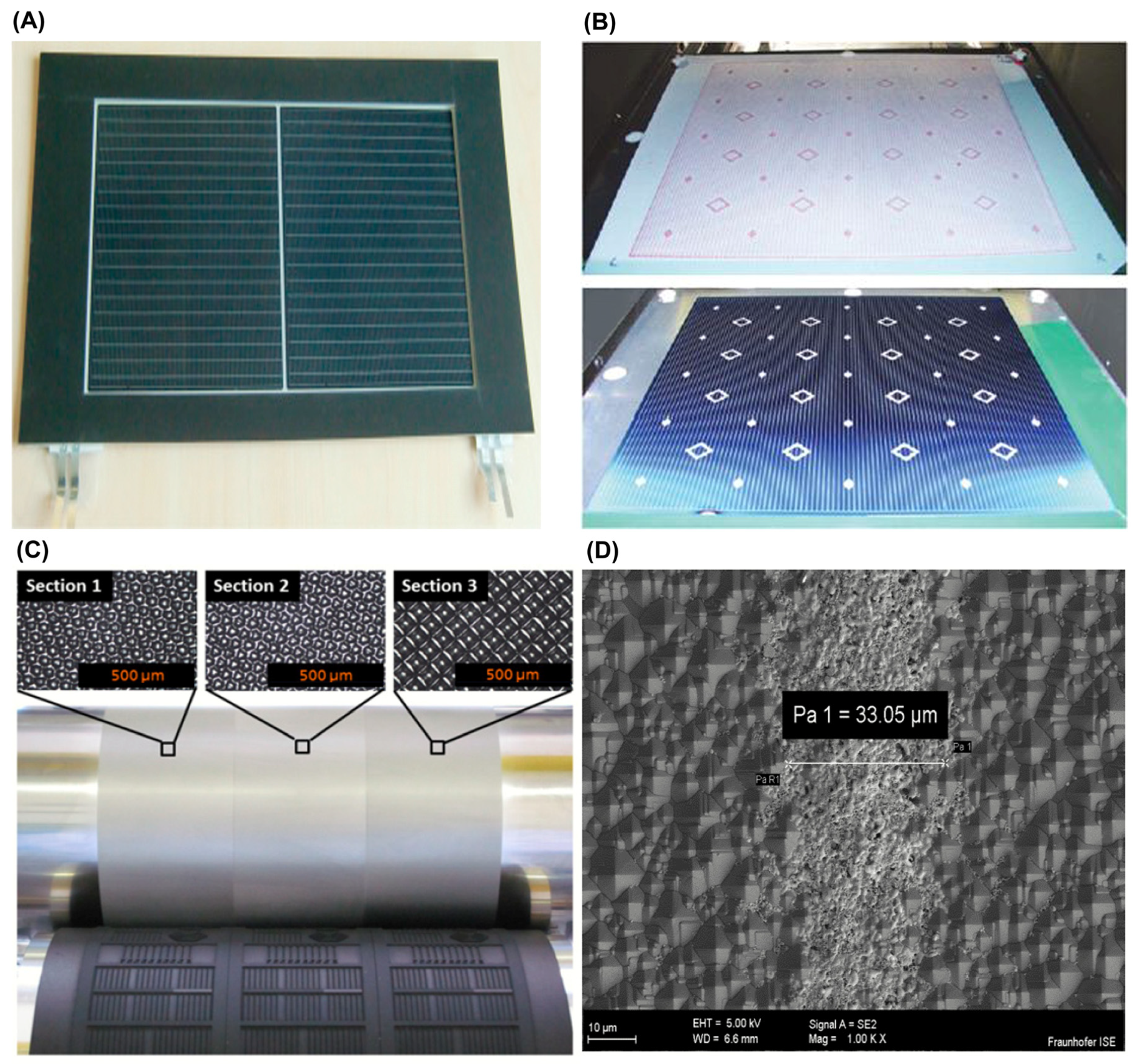
Front-side metallization of multi-busbar solar cells.Silicon waferSilver-based ink (aerosol ink SISC)Producing a fine-line metallization of multi-busbar solar cells with 33 µm contact finger width[28]
Table 2. Summary of flexographic printing technique on polymer solar cells.
ApplicationSubstrateInkResultsReference
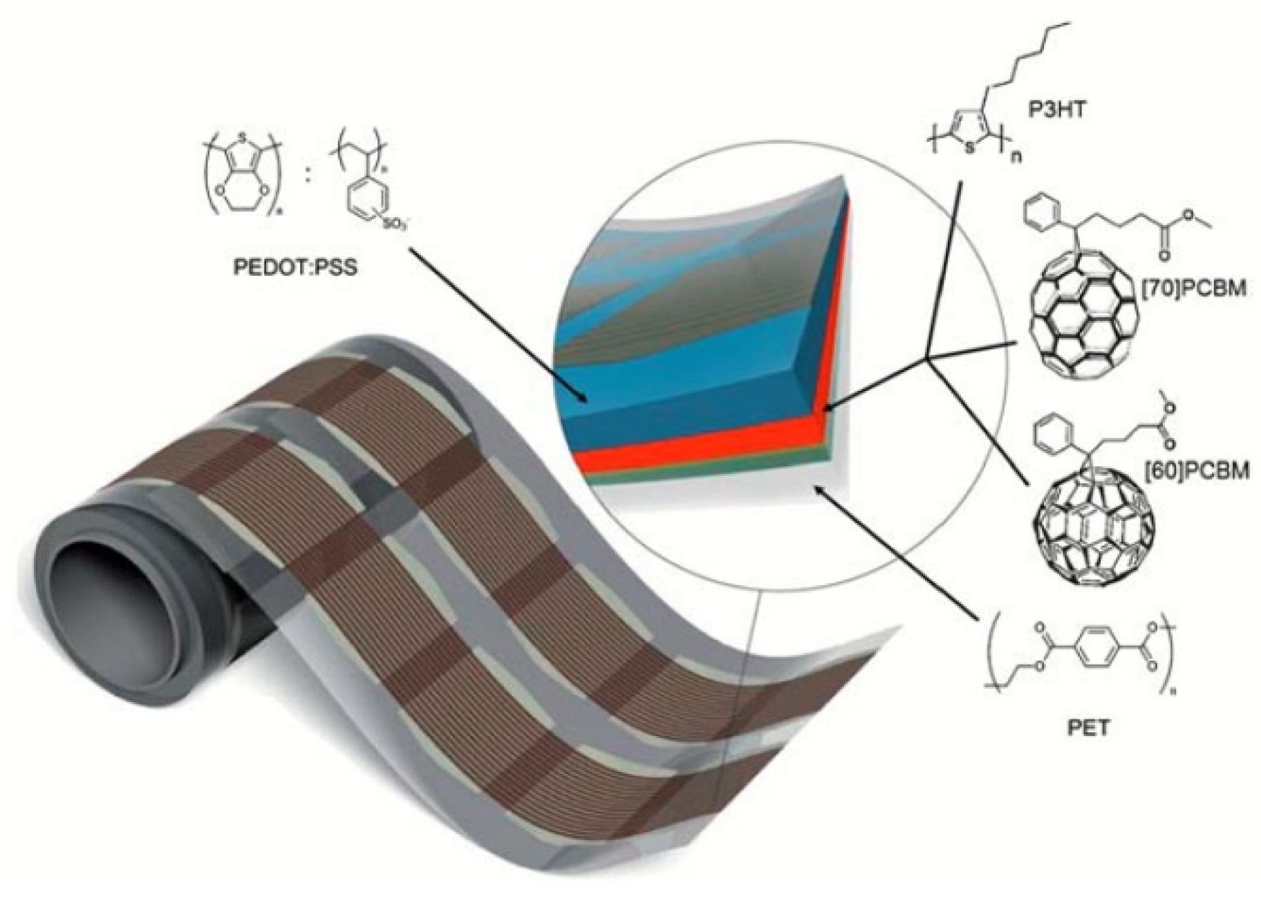
Printing 5 mm wide lines of ZnO, P3HT: [60/70] PCBM, PEDOT:PSS, and silver.ITO-PETLayer of n-octanol2.75% power conversion efficiency[27]
A novel layer structure (paper/Zn/ZnO/photoactive layer/PEDOT:PSS) for polymer/fullerene-based flexible photovoltaic cell.PaperPEDOT: PSS (1.5 wt% PEDOT PH1000 and 0.35 wt% PEDOT F010) in water including some surfactant mixture.1.31% power conversion efficiency[53]
Printing a hole-transporting layer (HTLs) for inverted OPV (ITO/ZnO/PCDTBT:PC70BM/VOx/Ag).ITO-coated
glass and PET
Vanadium oxide precursor3.5–4.5% power conversion efficiencies[61]
A photoactive layer of BHJ solar cells.Indium tin oxide (ITO) 130 nm thickness coated PET with125 µm thicknessZnO nanoparticles and sol-gel-based vanadium oxide inks. PCDTBT:PC71BM ink3.5% conversion efficiency[64]
Comparing three types of printing of the front conductive grid of (ITO) free polymer solar cells and raised topographies.PEDOT:PSS
PET
Water-based silver nanoparticle inks1.72% conversion efficiency[69]
Comparing four different R2R printing methods for printing back electrodes for polymer solar cell modules based on the Ione process.PEDOT:PSSWater-based silver inks-[70]
Disclaimer/Publisher’s Note: The statements, opinions and data contained in all publications are solely those of the individual author(s) and contributor(s) and not of MDPI and/or the editor(s). MDPI and/or the editor(s) disclaim responsibility for any injury to people or property resulting from any ideas, methods, instructions or products referred to in the content.

