Article

Research on Initiating Events Analysis of Small Helium-Xenon Gas Cooled Nuclear Reactor

1
Shanghai Institute of Applied Physics, Chinese Academy of Sciences, Shanghai 201800, China
2
University of Chinese Academy of Sciences, Beijing 100049, China
*
Authors to whom correspondence should be addressed.
Energies 2023, 16(19), 6769; https://doi.org/10.3390/en16196769
Submission received: 30 June 2023 / Revised: 15 August 2023 / Accepted: 20 September 2023 / Published: 22 September 2023
(This article belongs to the Special Issue New Advances and Novel Technologies in the Nuclear Industry)

Abstract

:
Initiating event analysis is an essential prerequisite of conducting probabilistic safety assessment for nuclear reactors, which plays an important role in improving the core design, identifying fault, and guiding operation. In order to determine the initiating event list of SIMONS (Small Innovative helium-xenon cooled Mobile Nuclear power System), preliminary researches on the initial event of SIMONS were carried out using the MLD (Main Logic Diagram) analysis method and referring to the initial event list and initial event analysis theory of other nuclear reactors such as HTGR (High Temperature Gas-cooled Reactor), MSR (Molten Salt Reactor), and PWR (Pressurized water reactor). With employing these methods, a total of 31 initial events are identified for SIMONS based on its latest conceptual design. These initial events are then divided into six groups according to the accident types, which are core heat removal increase, core heat removal decrease, abnormal reactivity and power distribution, pipeline crevasse and equipment leakage, anticipated transients without scram, and disasters (internal and external). The obtained results can provide a theoretical basis for the further safety analysis of SIMONS.

1. Introduction

Small nuclear reactors have received widespread attention from the international nuclear industry due to their short construction period, strong adaptability, low siting cost, high safety, and ability to realize mobile deployment by vehicle or shipboard [1]. For megawatt-class small nuclear reactor power sources, the technological approach of using gas-cooled fast reactors with Brayton cycles has been widely accepted worldwide [2,3,4,5]. In terms of working fluid, the helium-xenon gas mixture can improve the performance of the Brayton cycle as well as operate as a direct reactor coolant [6]. Currently, conceptual design work for Small Innovative helium-xenon cooled MObile Nuclear power Systems (SIMONS) has been carried out in China [7].
Probabilistic Safety Assessment (PSA) is an important reactor safety analysis method that provides guidance for the design and safe operation of reactors. It applies probability risk theory to evaluate the safety of the reactor system, believing that a reactor accident is a random event with many potential factors causing it. The safety of the reactor should be represented by the mathematical expected value (i.e., risk) of all potential accidents [8]. Compared with deterministic safety assessment approaches based on design basis accidents, the PSA method not only studies the physical phenomena, processes, and consequences that occur after an event happens, but also evaluates the risk quantitatively on this basis. Furthermore, the PSA method employs more realistic assumptions to represent the actual state of the reactor, and its evaluation results are closer to reality. In the application of probabilistic safety assessment, it can be divided into three levels, as shown in Table 1.
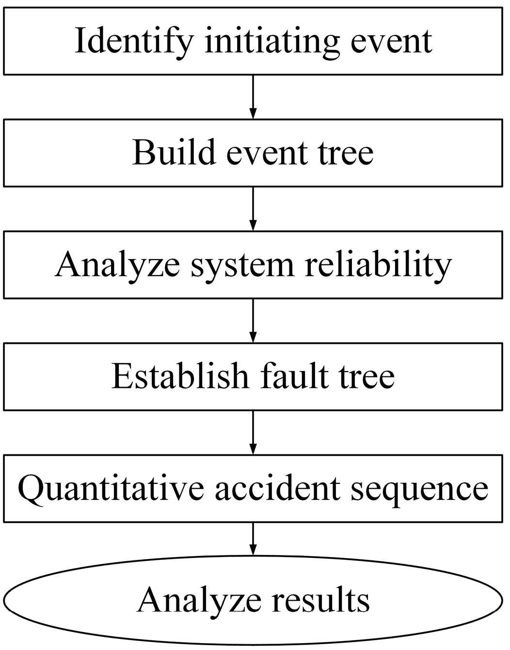
The basic process of the PSA-I method is shown in Figure 1. The first step in implementing PSA is to generate a list of initiating events to be analyzed. An initiating event is defined as an event that causes a disturbance in a nuclear power plant and has the potential to result in radioactive release consequences (core damage) [
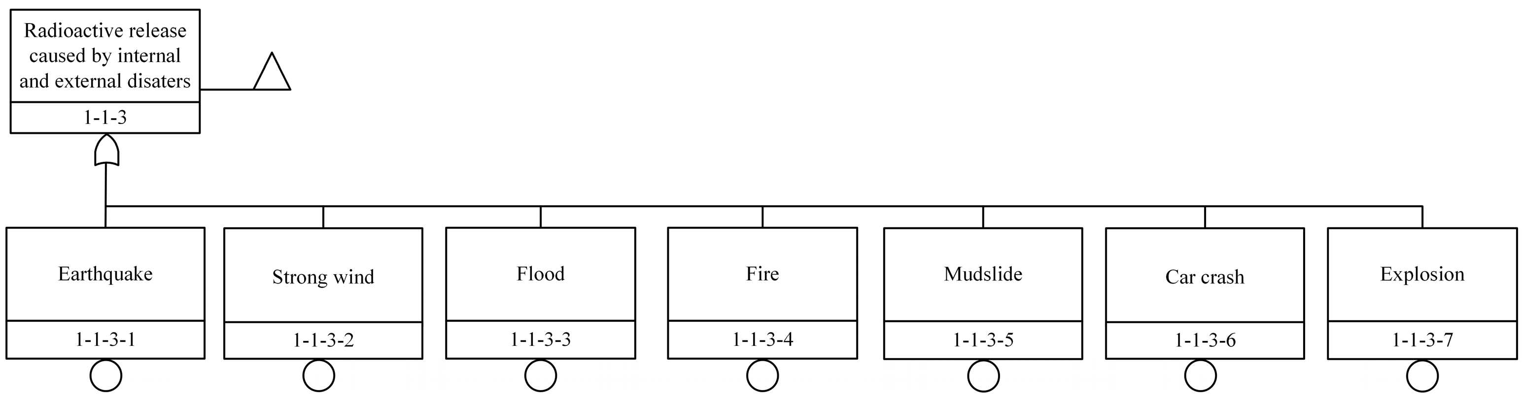
9], and it is divided into two categories: internal events induced by equipment failure, personnel error, etc., and disasters caused by earthquakes, floods, fires, and projectile impacts. The purpose of initiating event analysis is to identify all possible initiating events as completely as possible for the following phase of accident sequence analysis [10]. Correctly identifying the initiating event is of great significance for improving the credibility of reactor PSA analysis.
Currently, research on the initiating events of Pressurized Water Reactors (PWR, cooled by light water) [11], Boiling Water Reactors (BWR, cooled by light water) [12], Molten Salt Reactors (MSR, cooled by molten salt) [9,10], Hight Temperature Gas-cooled Reactors (HTGR, cooled by helium, carbon dioxide, etc.) [8,13], and other reactors has been conducted worldwide. However, there is little research on the initiation events of small modular HTGR cooled by Helium-xenon. This study primarily investigates and analyses the initiating events of SIMONS (cooled by Helium-Xenon).
The remaining sections of this study are organized as follows: Section 2 discusses the methodology for identifying initiating events. Section 3 presents the conceptual design of SIMONS. Section 4 contains the results of this study. The concluding remarks of this study are given in Section 5.

2. Methodology

There are four primary approaches for identifying initiating events, which are [14]:
  • Engineering Evaluation: Systematically analyzing the reactor system and major equipment to identify failure modes that, either directly or in combination with other failures, could lead to a release of radioactivity. This method relies on the completeness of the design information, and it is difficult to obtain truly valid information for engineering analysis in the early stages of innovative design when design information is insufficient.
  • Reference List: Referring to the initiating events of other nuclear power plants, especially similar nuclear power plants, to identify initiating events that are applicable to the research object.
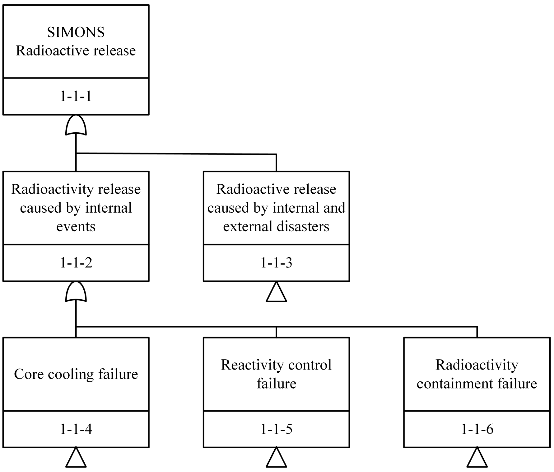
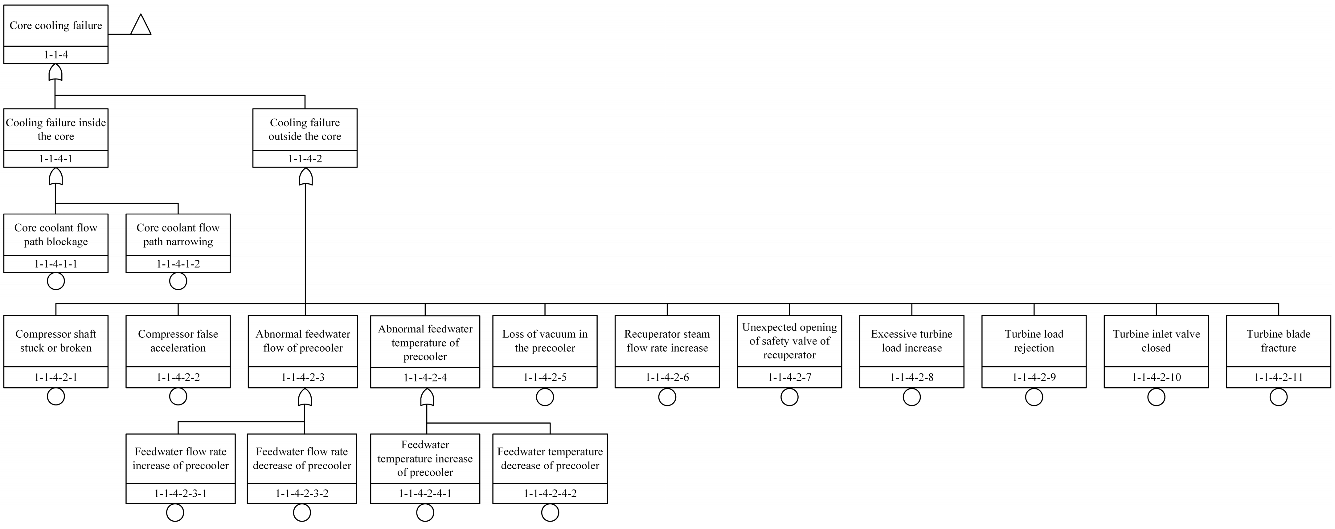
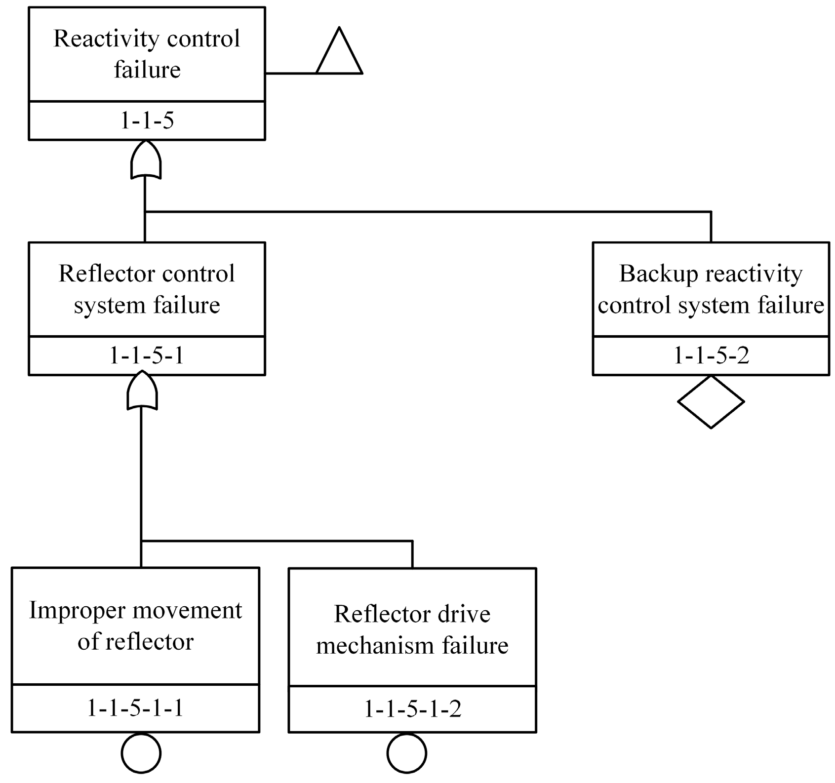
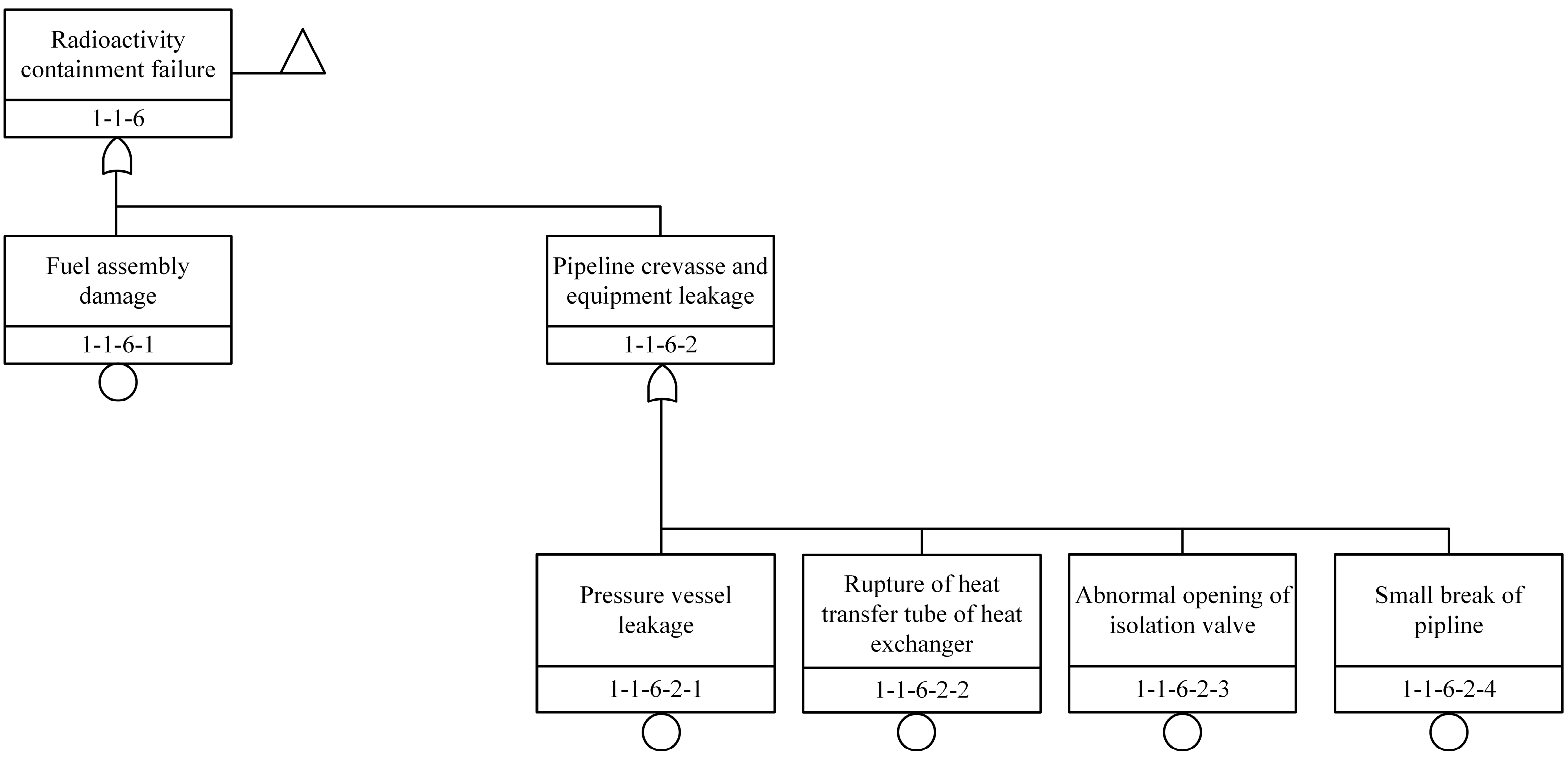
  • Deductive Analysis: Using a method similar to Fault Tree (such as Master Logic Diagram, MLD), the top event (such as a large release of radioactivity) is gradually decomposed into different categories of events that may lead to the occurrence of this consequence, and the initiating events can be selected from each event at the bottom level.
  • Operational Experience: Analyzing the feedback from the operational history of the plant under investigation and similar nuclear plants to identify initiating events that should be added. Consultation of nuclear plant operators, maintenance employees, engineers, and safety analysts can be also made to check whether some important initiating events were overlooked. Compared with Reference List, which aims to form a preliminary list of initiating events with a focus on evaluating the applicability of previous initiating events to new research subjects, the Operational Experience method aims to form a relative complete list of initiating events, with a focus on whether the initiating events to be considered are missing.
As the mature type of nuclear reactor, current commercial water-cooled nuclear reactors, including Pressurized Water Reactor (PWR) and Boiling Water Reactor (BWR), have been extensively studied in the aspects of initiating event identification using the methods of engineering evaluation and operational experience [15]. A series of related publications can be found and among them, WASH-1400 is considered to be an epochal technical report, published by the U.S. Department of Energy (DOE) in 1975, which is also the first and complete technical report for PSA analysis [12], evoking research activities on PSA analysis worldwide. This report concluded that the risks to the individual posed by nuclear power stations were acceptably small, compared with other tolerable risks. Specifically, this report concluded that the probability of a complete core meltdown is about 1 in 20,000 per reactor per year by using the methods, resources, and knowledge at the time. For the advanced nuclear reactors, such as the liquid metal-cooled reactor, Molten Salt Reactor (MSR), Gas Cooled Reactor (GCR), etc., methods for initiating event identification need to be determined based on the characteristics of the specific reactor because of the diversity of reactor types, advanced design, and lack of engineering construction and practical operation experience.
Table 2 shows the identification of initiating events for different types of reactors. In the European Union (EU), 34 initiating events in six categories were identified for the Advanced Lead-cooled Fast Reactor European Demonstrator (ALFRED) using the MLD method [16]. In Japan, 77 internal initiating events in 15 categories were identified for the prototype sodium-cooled fast reactor MONJU via a combination of MLD and Engineering Evaluation methods [17]. Shanghai Institute of Applied Physics (SINAP) of China screened 37 initiating events in six categories of Thorium-based Molten Salt Reactor with Solid Fuel (TMSR-SF1) by MLD and the Reference List method [9]. The Nuclear Research Institute of Tsinghua University in China obtained 40 initiating events in six categories for the High-Temperature Gas-cooled reactor (HTR-10) using all four methods mentioned above [8].
The identification of initiating events for new reactors does not have strict guidelines to follow, and it is generally a combination of multiple methods. The MLD method is a deductive analysis method widely used in identifying initiating events. It starts with the nature of the event cause and the conventional reactor event categories, then uses causal logic to reason and list the events layer by layer until obtaining the bottom-level events grouped by category as the list of reactors initiating events [9].
Considering that SIMONS is still in the conceptual design stage, several relevant system designs and information are still unknown, and there is no historical operation experience reference. As a result, this research mainly uses the MLD method and also refers to the list of initiating events of other reactors (especially helium-cooled reactors [18,19] and carbon-dioxide cooled reactors [13]) to derive the initiating events for SIMONS.

3. SIMONS

The electrical power of SIMONS is 8 MW with a thermal power of 20 MW. SIMONS uses Helium-Xenon as coolant. Compared with other gaseous coolants such as air and nitrogen, helium (as an inert gas) has excellent heat transfer performance and avoids the aforementioned problems. Moreover, adding a certain amount of xenon gas to helium can solve the problem of difficulty in compressing when using a single helium gas [6].
In order to fulfill the design criteria of reactor mobility, the whole system is separated into three parts: core, energy conversion system, and shielding system.

3.1. Core

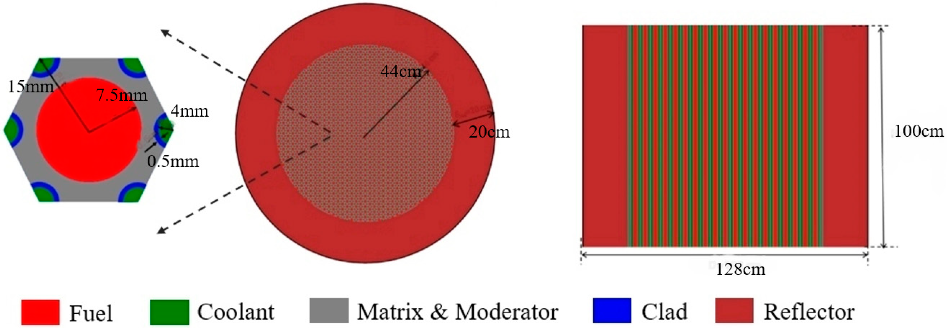
The core structure of SIMONS is shown in Figure 2. SIMONS uses uranium carbide with U-235 enrichment achieving 19.75% as the fuel, helium-xenon gas as the coolant, and graphite as the moderator. The entire core is in a cylindrical shape with a radius of 44 cm and a height of 100 cm, and it is formed by graphite hexagons (1.5 cm pitch) with each one pierced by a channel (0.75 cm radius) for fuel circulation. Six coolant channels are symmetrically placed around the fuel rod, and each coolant channel (0.4 mm radius) is wrapped in a layer of Mo-TZM shell with a thickness of 0.05 cm. Around the core, a beryllium oxide reflector with a thickness of 20 cm is set to minimize the neutron leakage. The detailed core design parameters of SIMONS are shown in Table 3.
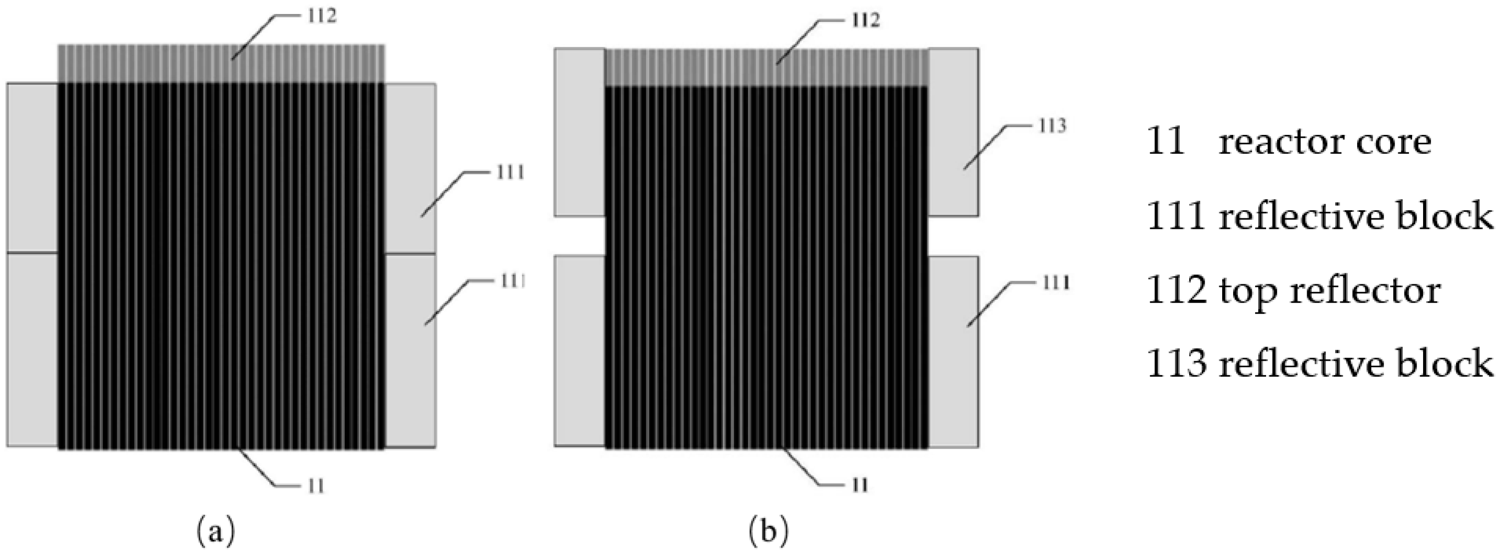
Unlike conventional reactors, which rely on control rods to regulate reactivity, SIMONS mainly controls the reactivity of the core during the whole life cycle by pulling the reflector outside the core [20]. The pull-out reflector includes multiple pull-out reflective blocks, which are axially arranged on the outer side of the core. During core operation, at least one pull-out reflective block can axially move to adjust the core reactivity. Figure 3 shows two operational states for a core design equipped with two axial pull-out reflective blocks. In Figure 3a, two axial pull-out reflective blocks completely close, which corresponds to the fully closed state of the reflector and minimizes the neutron leakage. In Figure 3b, the upper pull-out reflective block (labeled 113) axially moved up over a certain distance, forming a neutron leakage channel between the two reflective blocks, thereby changing the neutron reflection effect of the pull-out reflector.
Meanwhile, to ensure sufficient safety, SIMONS will be equipped with an auxiliary reactivity control system, which, however, has not been determined yet in terms of the design.

3.2. Energy Conversion System

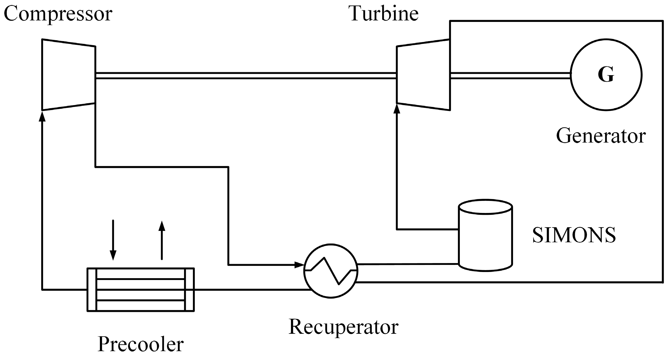
SIMONS employs a highly efficient closed Brayton cycle with helium-xenon gas as the working fluid. The energy conversion system (PCS) is composed of a compressor, a recuperator, a precooler, and a turbine. 
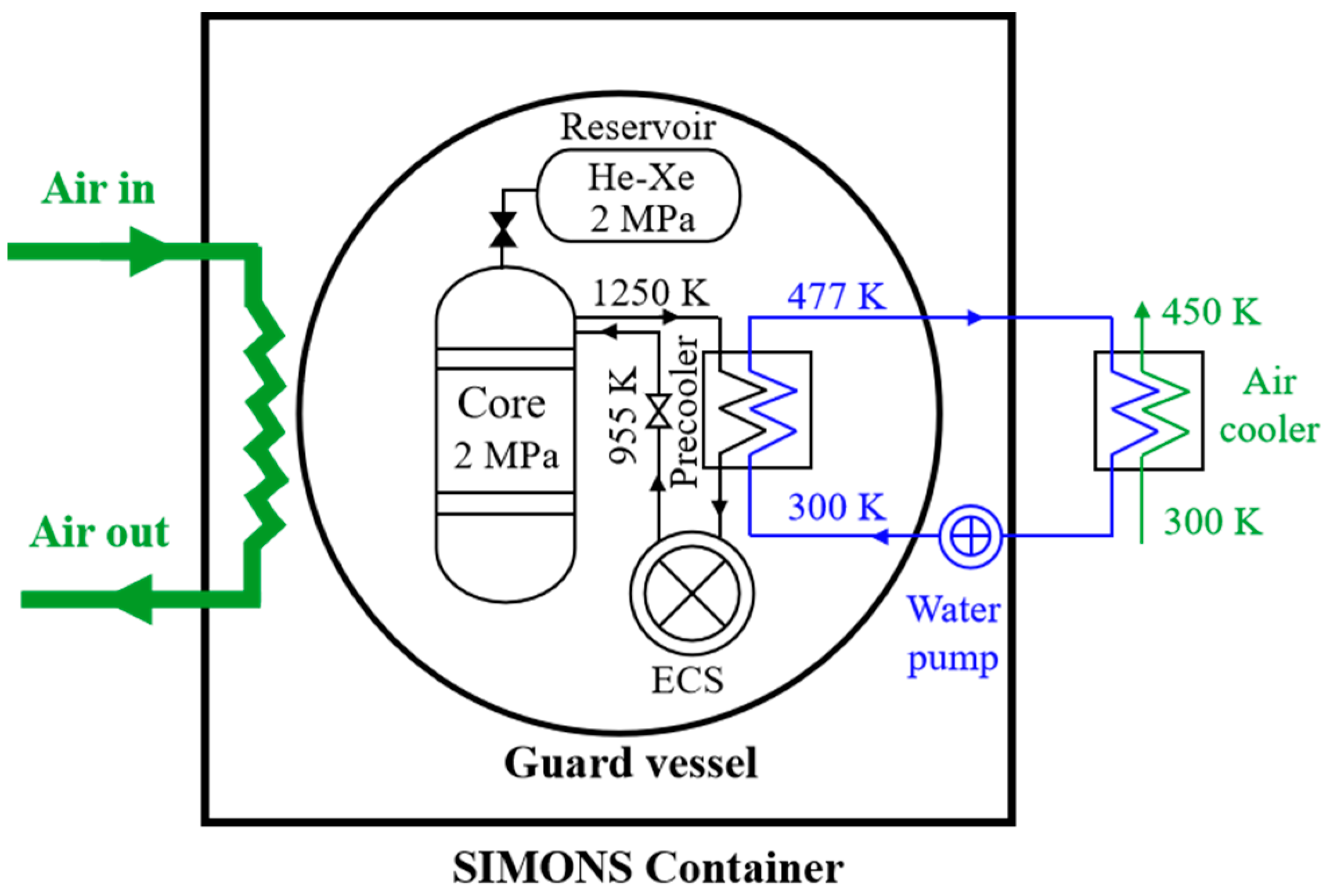
Figure 4 depicts a schematic diagram of the energy conversion structure based on the Brayton cycle. The helium-xenon working fluid in low-temperature and low-pressure is pressurized by the compressor, and then exchanges heat with the exhaust gas from the turbine in the recuperator. After preheating to a certain temperature, it is further heated by SIMONS, and then enters the turbine to drive the generator to generate electricity. The exhausted gas flows to the recuperator, in which the exhausted gas is cooled, and then enters the precooler for further cooling, and finally enters the compressor for compression to complete the entire cycle. In order to make the whole system compact, SIMONS adopts a single stage compression and single stage expansion method, which only includes one compressor and one turbine in the whole system. Moreover, the arrangement of the rotating shaft shared by the compressor, turbine, and generator is used to reduce the loss of system efficiency and improve the compactness of the system.
Figure 5 shows the layout of the SIMONS safety system. Under normal operating conditions, the front cooler is connected to the external air cooler through a light water working medium to remove the waste heat of the Brayton cycle system. While under accident conditions, the residual heat from the reactor core is carried out by direct air cooling. The heat exchange equipment uses printed circuit heat exchangers (PCHE) that are resistant to high temperature and pressure, high strength, and high heat transfer efficiency.

3.3. Shielding System

The overall design strategy of the SIMONS shielding system is a combination of fixed shielding inside the module and detachable shielding outside the module, with γ-rays and neutrons jointly shielded to ensure that the radiation dose rate in the reactor personnel operation area and equipment area is less than 2 × 10⁻³ Sv/h. Highly efficient lightweight shielding materials (such as rolled steel, polyimide Gd PI, etc.) are used to ensure the shielding effect and at the same time reduce the weight of the whole reactor power system. 
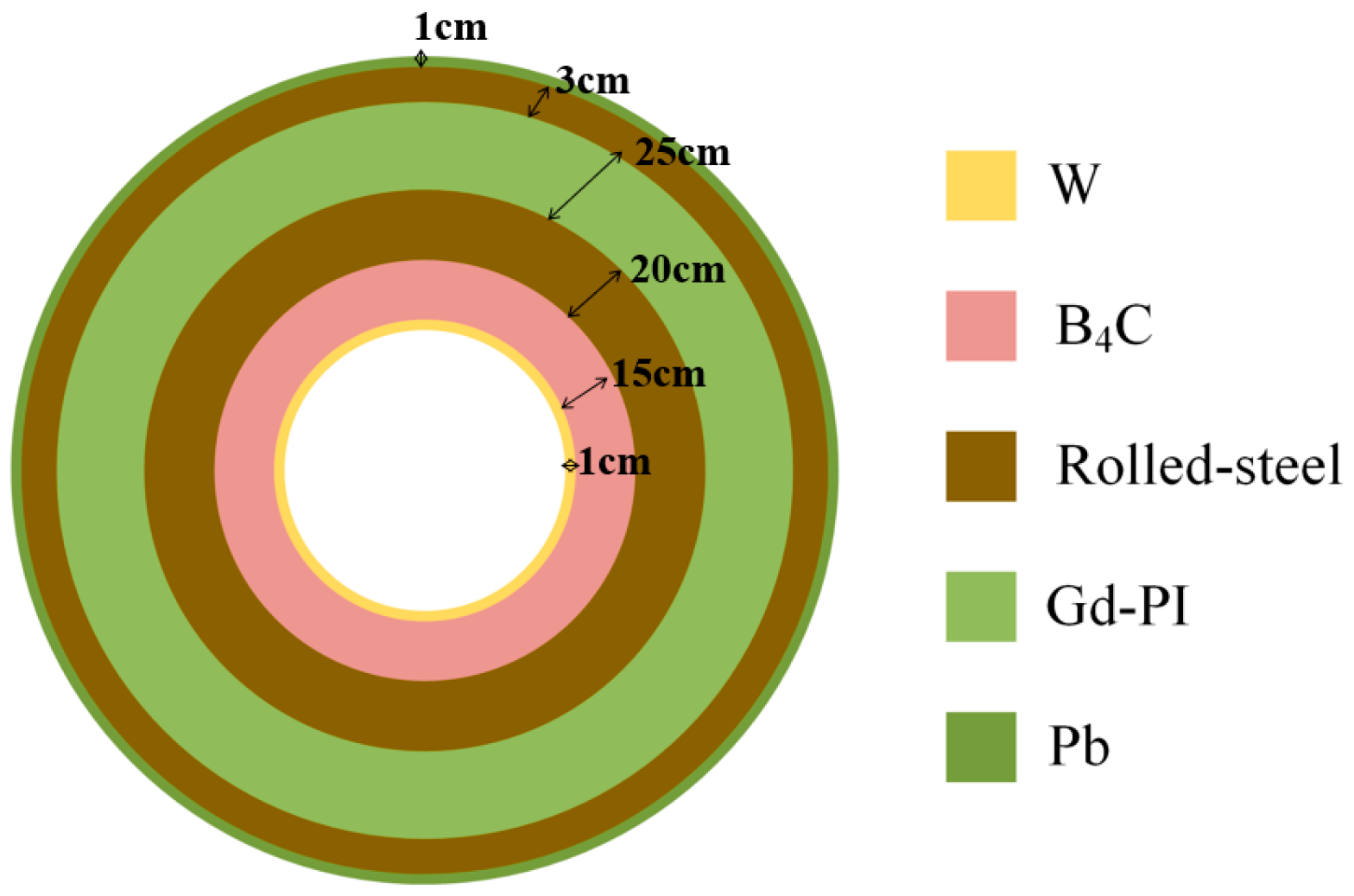
Figure 6 shows the layout diagram of the internal axial shielding of the SIMONS module, which is from the inside to the outside: 1 cm tungsten, 15 cm boron carbide, 20 cm rolled steel, 25 cm polyimide, 3 cm rolled steel, and 1 cm lead.
In terms of safety, the design of SIMONS mainly has the following characteristics [21]: (1) Compact integrated design, no large circuit pipelines, eliminating the possibility of hypothetical large break accidents; (2) Helium-xenon gas is a noble gas and will generally not react with other materials, greatly reducing the corrosion of materials; (3) Mainly relying on moving the reflective layer to achieve reactivity control, reducing the occurrence of accidents such as rod bouncing and sticking; (4) Passive safety design, relying solely on the passive decay heat removal system can also ensure that the fuel temperature is below the core melting limit after shutdown, avoiding the occurrence of “core meltdown” phenomenon.

4. Results

Although there is a requirement to have a list of initiating events as complete as possible, it must be recognized that it is not possible to form an absolutely complete list of initiating events. It is only desirable that the contribution of unidentified initiating events to the total risk should be minimal.

4.1. Determination of Initiating Events

4.1.1. Main Logic Diagram

To determine the initiating events of SIMONS using the MLD method, the target event has to be selected first. SIMONS benefits from the excellent fuel element performance and the design of passive residual heat removal system, which does not suffer from “core meltdown” like the pressurized water reactor. Moreover, the use of radioactive release as a consequence of PSA analysis for modular high-temperature gas-cooled reactors has been confirmed [22]. Therefore, SIMONS takes radioactive release as the target event of the main logic diagram and based on SIMONS’ current conceptual design, starting from the three major safety functions of the reactor (reactivity control, residual heat removal, and radioactive containment), identifies the frontier systems that lead to the failure of the corresponding safety functions. Then, the support equipment leading to the failure of the frontier systems is determined according to the failure of the frontier system. After reasoning and listing the events layer by layer, the bottom-level events grouped by category are finally obtained as the list of initiating events of SIMONS. Some explanations of shape symbols used in main logic diagram can be found in Appendix A.
Figure 7 shows the main logic diagram for the preliminary analysis of the initiating event of SIMONS radioactive release, where the internal events and disasters (internal and external) during the power operation phase are mainly considered. The “radioactive release” in the top event is a broad concept, which not only includes radioactive leakage caused by critical physical and thermal parameters in the core exceeding relevant limits, system component failure, but also radioactive leakage caused by equipment, pipeline breakage, etc.
Figure 8 represents the main logic diagram of the preliminary analysis of the initiating events of SIMONS core cooling failure. During normal operation, the primary coolant is heated as it flows through the SIMONS core, taking away core heat, and is then cooled in the heat exchanger. The cooling failure of the core is divided into two parts: cooling failure inside the core and cooling failure outside the core. Among them, cooling failure inside the core considers the core coolant flow path blockage due to deposition of graphite dust and accumulation of corrosion activation products, and the core coolant flow path narrowing due to irradiation swelling of graphite components. While the cooling failure outside the core mostly takes into account the failure of compressor, precooler, recuperator, and turbine. Furthermore, compressor failure includes two scenarios: compressor shaft stuck or broken, and compressor false acceleration. The former reduces core heat removal, while the latter increases core heat removal. Similarly, the failure of the recuperator, precooler, and turbine is also considered in terms of causing a decrease in core heat removal and an increase in core heat removal. The specific content is shown in Figure 6 and will not be elaborated here.
Figure 9 indicates the main logic diagram for the preliminary analysis of the initiating event of SIMONS reactivity control failure. SIMONS is set up with two reactivity control systems. The reflector control system is the first shutdown system, which performs the power regulation and shutdown functions. A secondary shutdown system is available for cold shutdown in case the first shutdown system is not functioning. However, since the current SIMONS concept design does not have a complete design of the backup shutdown system, the failure of the backup reactor control system is temporarily treated as a pending development event. The failure of the reflector control system is mainly considered in the case of improper movement of the reflector due to operator error, as well as failure of the reflector drive mechanism due to reflector shaft stuck, loss of control power, etc.
Figure 10 depicts the main logic diagram for the preliminary analysis of the initiating event for SIMONS radioactive containment failure, where the fuel assembly damage and pipeline crevasse and equipment leakage are discussed.
Figure 11 demonstrates the main logic diagram for the preliminary analysis of the initiating event for SIMONS disasters. Considering that the design goal of SIMONS is mainly the mobile nuclear reactor power supply for land use, some common natural disasters and accidents on land are given special attention.

4.1.2. Reference List

Since SIMONS (helium-xenon gas-cooled) and HTR-10 (helium-cooled) [8] are both high-temperature gas-cooled fast reactors, there are certain similarities in their design characteristics, and the latter has completed the primary PSA analysis work and successfully achieved criticality. Therefore, the experience and technology accumulation of HTR-10 initiating events identification has an important guiding role in the selection of SIMONS initiating events. Table 4 compares the similarities and differences between the design characteristics of SIMONS and HTR-10.
Based on the analysis results in Table 4 and referring to the initiating events list of HTR-10 [8], anticipated events such as “loss of off-site power (ATWS)” and “loss of normal feedwater (ATWS)” that failed to scram were added as the initiating events for SIMONS.
Finally, a preliminary list of SIMONS initiating events was determined, including a total of 31 initiating events (See in Table 5).

4.2. Grouping of Initiating Events

In order to reduce the workload of PSA analysis, it is necessary to group the initiating events according to safety functions or system responses. All initiating events within the same group basically have the same frontier system success criteria and have the same special conditions (for operator requirements, nuclear power plants automatically respond) [8]. As shown in Table 5, referring to the fault classification method of HTR-10, the initiating events of SIMONS are divided into six groups: core heat removal increase, core heat removal decrease, abnormal reactivity and power distribution, pipeline crevasse and equipment leakage, anticipated transients without scram, and disasters (internal and external).

5. Conclusions

Based on the latest conceptual design of SIMONS, a small helium-xenon cooled reactor, this paper conducted a preliminary exploratory study of the initiating events of SIMONS using a combination of MLD and referring to other reactors (especially helium-cooled reactors and carbon-dioxide cooled reactors) initiating lists and initiating event selection experience, which lays an important foundation for further in-depth and detailed PSA analysis. The main conclusions are as follows:
  • Taking the generalized “radioactive release” as the top event, the internal initiating events of the power operation phase of SIMONS were derived, and together with the disasters (internal and external), 31 initiating events of SIMONS were identified;
  • According to the classification of failure types, SIMONS initiating events are classified into six groups: core heat removal increase, core heat removal decrease, abnormal reactivity and power distribution, pipeline crevasse and equipment leakage, anticipated transients without scram, and disasters (internal and external).
At present, SIMONS is still in the conceptual design stage, and the design of some systems is not yet complete. Subsequently, with the progress and improvement of SIMONS design in the future, based on the current work and combined with different application scenarios of SIMONS, further in-depth exploration will be conducted on the analysis of the initiating events of SIMONS, and the completeness and applicability of the initiating events of SIMONS will be fully demonstrated.

Author Contributions

Conceptualization, J.Z. and J.W.; methodology, J.Z., Y.C., H.Z. and C.Z.; validation, J.Z., J.W., Y.C., H.Z., C.Z. and J.C.; formal analysis, J.Z., J.W., Y.C., H.Z., C.Z. and J.C; investigation, J.Z., J.W., Y.C. and C.Z.; resources, J.W., C.Z. and J.C.; writing—original draft preparation, J.Z.; writing—review and editing, J.W., C.Z. and J.C. All authors have read and agreed to the published version of the manuscript.

Funding

This research was funded by National Key R&D Program of China (2020YFB1901900).

Data Availability Statement

The data used to support the findings of this study are included within the article.

Acknowledgments

The authors would like to sincerely thank the anonymous reviewers for their constructive comments on this paper.

Conflicts of Interest

The authors declare no conflict of interest.

Abbreviations

SIMONSSmall Innovative helium-xenon cooled MObile Nuclear power System
MLDMain Logic Diagram
HTGRHigh Temperature Gas-cooled Reactor
MSRMolten Salt Reactor
PWRPressurized Water Reactor
PSAProbabilistic Safety Assessment
BWRBoiling Water Reactor
DOEDepartment Of Energy
GCRGas Cooled Reactor
EUEuropean Union
ALFREDAdvanced Lead-cooled Fast Reactor European Demonstrator
SINAPShanghai Institute of Applied Physics
TMSR-SFThorium-based Molten Salt Reactor with Solid Fuel
PCSPower Conversion System
PCHEPrinted Circuit Heat Exchanger
ATWSAnticipated Transients Without Scram

Appendix A

Table A1. Explanation of symbols in the main logic diagram.
SymbolNameExplanation
Energies 16 06769 i001Basic eventEvents that do not require further development
Energies 16 06769 i002Pending development eventEvents that have not yet developed due to certain reasons
Energies 16 06769 i003Transfer symbolReceiving input from other diagrams or output to other diagrams
Energies 16 06769 i004OR gateEvent OR Operation, where the output event occurs if any of the input events occur

References

  1. Chen, W.; Jiang, S. Feasibility study on development of small nuclear power reactors in China. Nucl. Power Eng. 2013, 34, 153–156. [Google Scholar] [CrossRef]
  2. Taylor, R. Prometheus Project Final Report; Jet Propulsion Laboratory, National Aeronautics and Space Administration: Washington, DC, USA, 2005. [Google Scholar]
  3. Allen, K.; Hartford, S.; Merkel, G. Feasibility study of a micro modular reactor for military ground applications. J. Def. Manag. 2018, 8, 1000172. [Google Scholar] [CrossRef]
  4. Hernandz, R.; Todosow, M.; Brown, N.R. Micro heat pipe nuclear reactor concepts: Analysis of fuel cycle performance and environmental impacts. Annu. Nucl. Energy 2019, 126, 419–426. [Google Scholar] [CrossRef]
  5. Li, Z.; Sun, J.; Liu, M.; Lang, M.; Shi, L. Design of a hundred-kilowatt level integrated gas-cooled space nuclear reactor for deep space application. Nucl. Eng. Des. 2020, 361, 110569. [Google Scholar] [CrossRef]
  6. Guo, K.; Wang, C.; Qiu, S.; Su, G.; Tian, W. Analysis on thermoelectric conversion characteristic of Braton Cycle in Megawatt-class nuclear electric propulsion system. At. Energy Sci. Technol. 2019, 53, 16–23. [Google Scholar] [CrossRef]
  7. Hu, W.; Deng, J.; Liu, X.; Li, Z.; Xue, B. Study on key parameters design of small helium xenon cooled reactor. Nucl. Tech. 2021, 44, 85–90. [Google Scholar] [CrossRef]
  8. Zhu, J. Nuclear Reactor Safety Analysis; Xi’an Jiaotong University Press: Xi’an, China, 2000. [Google Scholar]
  9. Mei, M.; Shao, S.; He, Z.; Chen, K. Research on initial event analysis for solid thorium molten salt reactor probabilistic safety assessment. Nucl. Tech. 2014, 37, 45–52. [Google Scholar] [CrossRef]
  10. Zuo, J.; Gao, X.; Li, C.; Song, W.; Wang, K.; Liu, Q.; Jing, J.; Zhang, C. Preliminary research of safety analysis for 10-MW thorium-based molten salt reactor-solid fuel. Nucl. Tech. 2017, 40, 59–68. [Google Scholar] [CrossRef]
  11. Wang, C.; Fan, K.; Liang, B.; Liu, J. Suggestions for Design Improvement of the AP1000 System Based on PSA Analysis Results. Nucl. Sci. Technol. 2015, 35, 723–728. [Google Scholar] [CrossRef]
  12. Nuclear Regulatory Commission. Reactor Safety Study: An Assessment of Accident Risks in US Commercial Nuclear Power Plants; Office of Scientific Technical Information, U.S. Department of Energy: Washington, DC, USA, 1975. [Google Scholar]
  13. Mao, H.; Zhang, D.; Gao, C.; Wu, P.; Liu, Y.; Bi, S.; Mi, Z. Study of initial events and safety criteria for CO2 cooled reactor. Nucl. Tech. 2020, 43, 23–30. [Google Scholar] [CrossRef]
  14. Zuo, J.; Song, W.; Jing, J.; Zhang, C. Evaluation and Analysis of the Initiation Event of thorium molten Salt Experimental Reactor//Progress Report of Nuclear Science and Technology in China (Vol. 3). In Proceedings of the 2013 Annual Conference of the Chinese Nuclear Society, Vol. 3 (Nuclear Power), Harbin, China, 11 September 2013; pp. 272–279. [Google Scholar]
  15. Zuo, J.; Jing, J.; Bi, J.; Song, W.; Chen, K. Framework analysis of fluoride salt-cooled high temperature reactor probabilistic safety assessment. Nucl. Sci. Tech. 2015, 26, 050602. [Google Scholar] [CrossRef]
  16. Frignani, M.; Alemberti, A.; Tarantino, M. ALFRED: A revised concept to improve pool related thermal-hydraulics. Nucl. Eng. Des. 2019, 355, 110359. [Google Scholar] [CrossRef]
  17. Nishimura, M.; Fukano, Y.; Kurisaka, K.; Naruto, K. Updating of local blockage frequency in the reactor core of SFR and PRA on consequent severe accident in Monju. J. Nucl. Sci. Technol. 2017, 54, 1178–1189. [Google Scholar] [CrossRef]
  18. Keisty, G.; Oettingen, M.; Stanisz, P.; Cetnar, J. Statistical error propagation in HTR burnup model. Ann. Nucl. Energy 2017, 105, 355–360. [Google Scholar] [CrossRef]
  19. Oettingen, M.; Cetnar, J. Numerical modelling of modular high-temperature gas-cooled reactors with thorium fuel. Nukleonika 2021, 66, 133–138. [Google Scholar] [CrossRef]
  20. Liu, X.; Cai, X.; Guang, C.; Song, H. Control Methods, Devices, and Electronic Equipment for Helium-Xenon Cooled Reactors. CN114388162A, 22 April 2022. [Google Scholar]
  21. Wu, J.; Zhou, J.; Zou, C.; Jia, G.; Zhang, A.; Cai, X.; Chen, J. Accident occurrence frequency of a small helium-xenon gas cooled nuclear reactor system. Nucl. Tech. 2022, 45, 103–112. [Google Scholar] [CrossRef]
  22. Wu, Z.; Zhang, Z. Advanced Nuclear Energy System and High Temperature Gas Cooled Reactor; Tsinghua University Press: Beijing, China, 2004. [Google Scholar]
Figure 1. Flowchart of PSA-I.
Energies 16 06769 g001
Figure 2. Diagram of SIMONS core.
Energies 16 06769 g002
Figure 3. Arrangement of two pull-out reflective blocks. (a) represents the fully closed state of the reflector; (b) represents the fully open state of the reflector.
Energies 16 06769 g003
Figure 4. Diagram of energy conversion system based on Brayton cycle.
Energies 16 06769 g004
Figure 5. Layout of the SIMONS safety system.
Energies 16 06769 g005
Figure 6. Diagram of axial shielding of SIMONS.
Energies 16 06769 g006
Figure 7. Main logic diagram for the preliminary analysis of the initiating event of SIMONS radioactive release.
Energies 16 06769 g007
Figure 8. Main logic diagram of the preliminary analysis of the initiating events of SIMONS core cooling failure.
Energies 16 06769 g008
Figure 9. Main logic diagram for the preliminary analysis of the initiating event of SIMONS reactivity control failure.
Energies 16 06769 g009
Figure 10. Main logic diagram for the preliminary analysis of the initiating event for SIMONS radioactive containment failure.
Energies 16 06769 g010
Figure 11. Main logic diagram for the preliminary analysis of the initiating event for SIMONS disasters.
Energies 16 06769 g011
Table 1. Grade of Probabilistic Safety Assessment.
LevelContentsAims
PSA-IConducting reliability analysis on the operating and safety systems of nuclear power plants, determining the accident sequences that cause core damage, and conducting quantitative analysis to determine the frequency of each accident sequence, providing the probability of core damage occurring in each operating year of the reactorAssisting in analyzing the weaknesses of nuclear power plant and identifying the ways to prevent core damage in the phase of reactor design
PSA-IIAnalyzing the physical process of core meltdown and the characteristics of containment response, and determining the frequency of radioactive release from the containment based on the PSA-I resultsAnalyzing the severity of radioactive release caused by various core damage accident sequences, identifying design weaknesses, and providing specific suggestions on ways to mitigate the consequences of core damage accidents
PSA-IIIAnalyzing the migration of radioactive substances in the environment, determining the changes in radioactive concentration over time at different distances outside the nuclear power plant, and combining the results of PSA-II analysis to determine the off-site consequences of accidents based on the concept of public riskAnalyzing the relative importance of consequence mitigation measures, providing support for the designation of emergency response plans
Table 2. Identification of initiating events in different reactors.
ALFREDMONJUMSRHTR-10
DesignerEUJapanSINAPTsinghua
CoolantLeadSodiumMolten saltHelium
MLD1
Engineering Evaluation××
Reference List××
Operational Experience×××
Initiating event numbers34773740
Initiating event groups61566
1 In this table, the “√” symbol indicates that the corresponding reactor in the column utilized the initiating event identification method specified in the corresponding row, while the “×” symbol indicates that the reactor did not employ this method.
Table 3. Main parameters of SIMONS core.
ParametersValue
Thermal/electrical power (MW)20/8
Core radius (cm)44
Core height (cm)100
Fuel rod radius (cm)0.75
Coolant channel radius (cm)0.4
Coolant channel wall thickness (cm)0.05
Fuel rod number1027
Reflector thickness (cm)20
U-235 enrichment19.75%
Table 4. Main similarities and differences between SIMONS and HTR-10.
ItemsSIMONSHTR-10
SimilaritiesReactor typeHigh temperature gas cooled fast reactor
Thermodynamic cycle modeClosed Brayton cycle
Residual heat removal modePassive residual heat removal
DifferencesPower20 MWth/8 MWe10 MWth/3 MWe
Core typePrismaticPebble-bed
FuelUranium carbide (UC)Uranium dioxide (UO2)
CoolantHelium-XenonHelium
Primary circuit outlet/inlet temperature1200 K/914 K973 K/523 K
Fuel cycle modeOnce-through cycleMultiple continuous cycle
Reactivity control modeReflectorControl rod
Table 5. SIMONS initiating events lists and their grouping.
No.Accident TypesInitiating Events
1Core heat removal increaseCompressor false acceleration
2Feedwater temperature decrease
3Feedwater flow rate increase
4Recuperator steam flow rate increase
5Excessive turbine load increase
6Unexpected opening of safety valve of recuperator
7Core heat removal decreaseCore coolant flow path blockage
8Core coolant flow path narrowing
9Feedwater temperature increase
10Feedwater flow rate decrease
11Loss of vacuum in the precooler
12Turbine blade fracture
13Turbine inlet valve closed
14Turbine load rejection
15Compressor shaft stuck or broken
16Abnormal reactivity and power distributionImproper movement of reflector
17Reflector drive mechanism failure
18Pipeline crevasse and equipment leakagePressure vessel leakage
19Fuel assembly damage
20Rupture of heat transfer tube of heat exchanger
21Abnormal opening of isolation valve
22Small break of pipeline
23Anticipated transients without scram (ATWS)Loss of off-site power-ATWS
24Loss of normal feedwater-ATWS
25Disasters (internal and external)Earthquake
26Strong wind
27Flood
28Fire
29Mudslide
30Car crash
31Explosion
Disclaimer/Publisher’s Note: The statements, opinions and data contained in all publications are solely those of the individual author(s) and contributor(s) and not of MDPI and/or the editor(s). MDPI and/or the editor(s) disclaim responsibility for any injury to people or property resulting from any ideas, methods, instructions or products referred to in the content.

