

Analysis of Onshore Synthetic Inertia and Primary Control Reserve Contributions of Alternating Current-Side Meshed Offshore Grids with Voltage-Source Converter and Diode Rectifier Unit High-Voltage Direct Current Connections

Abstract
:1. Introduction
1.1. Motivation
1.2. Related Work and Contributions of This Article
2. Modeling
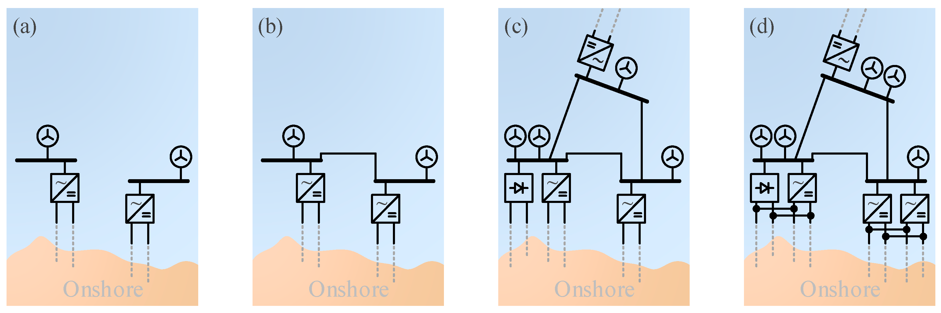
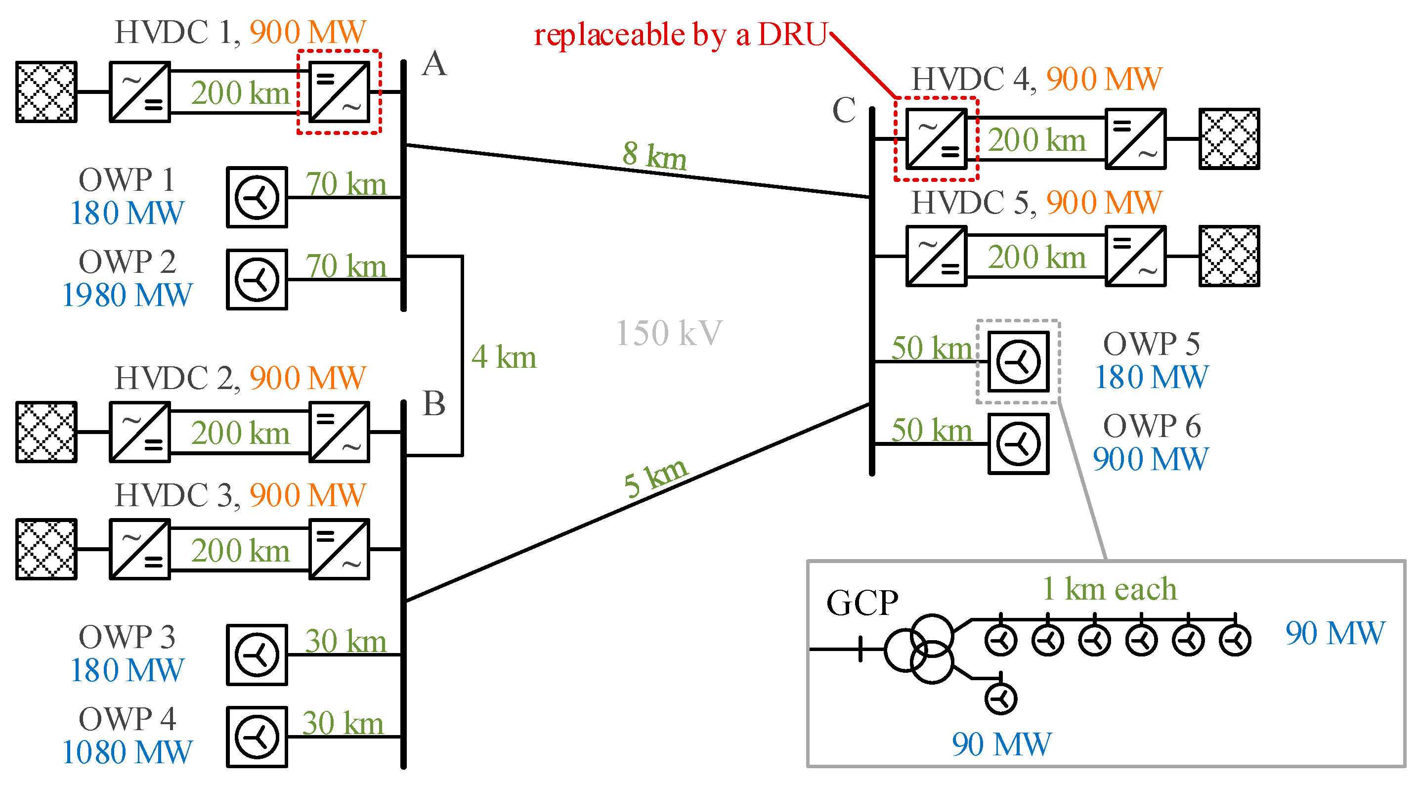
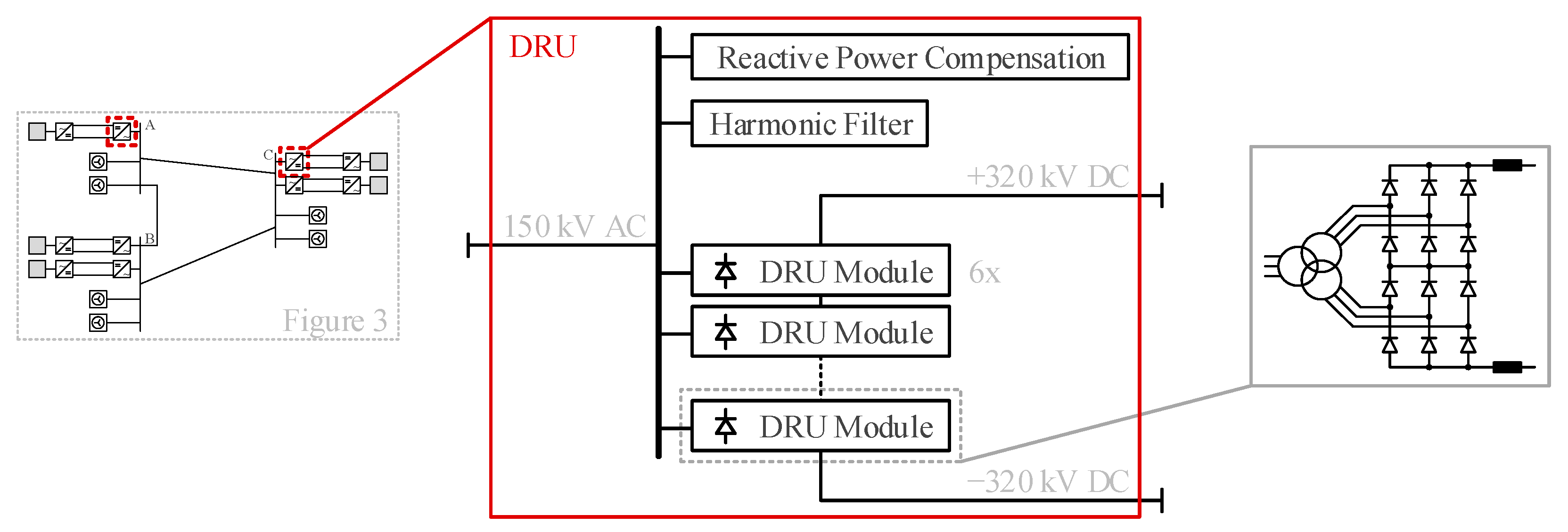
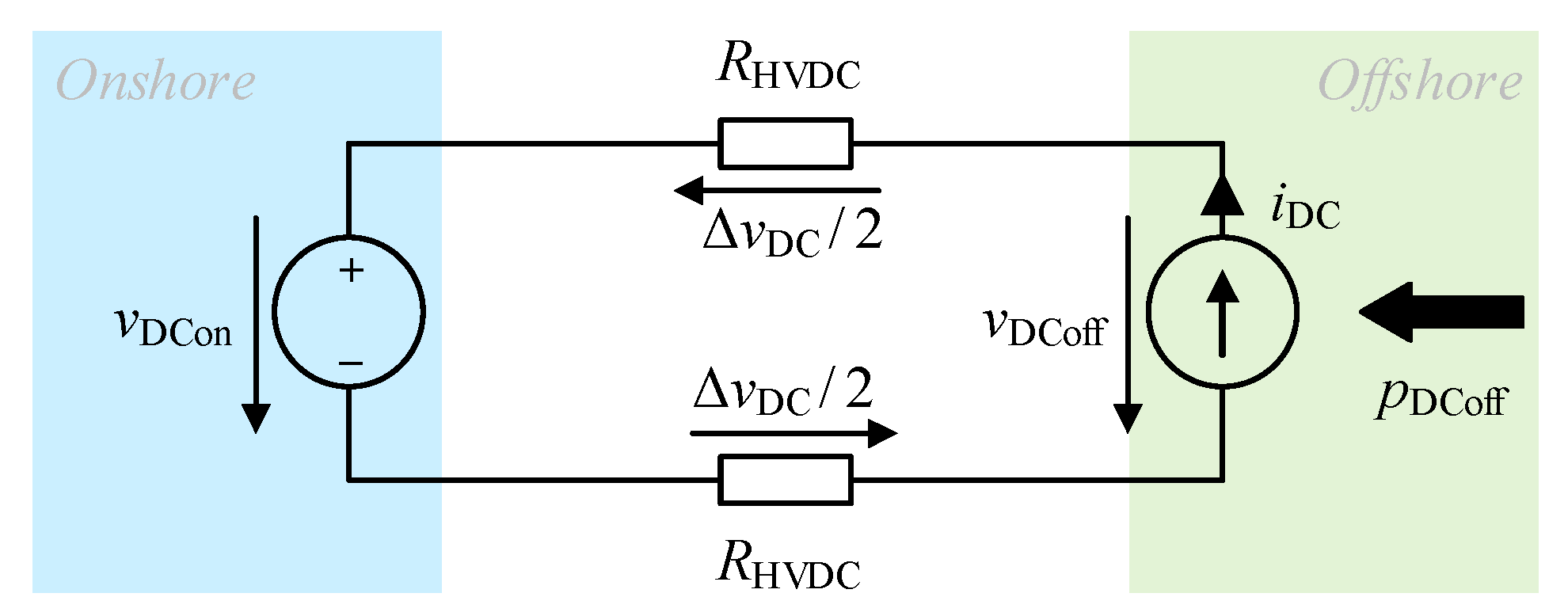
2.1. Grid Model
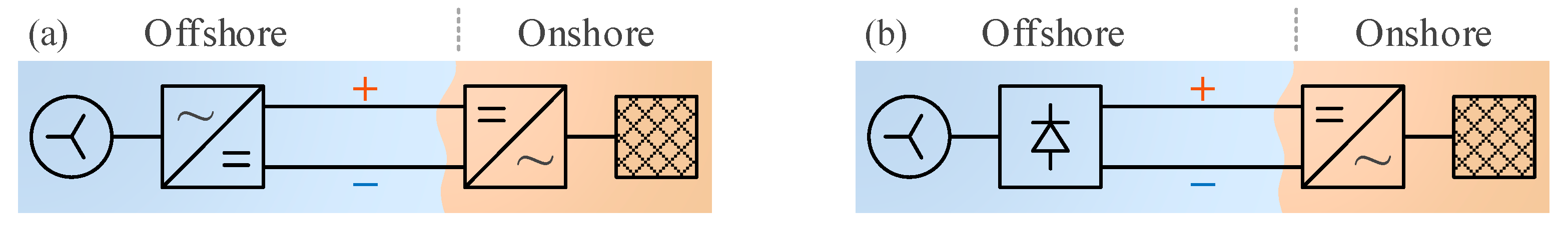
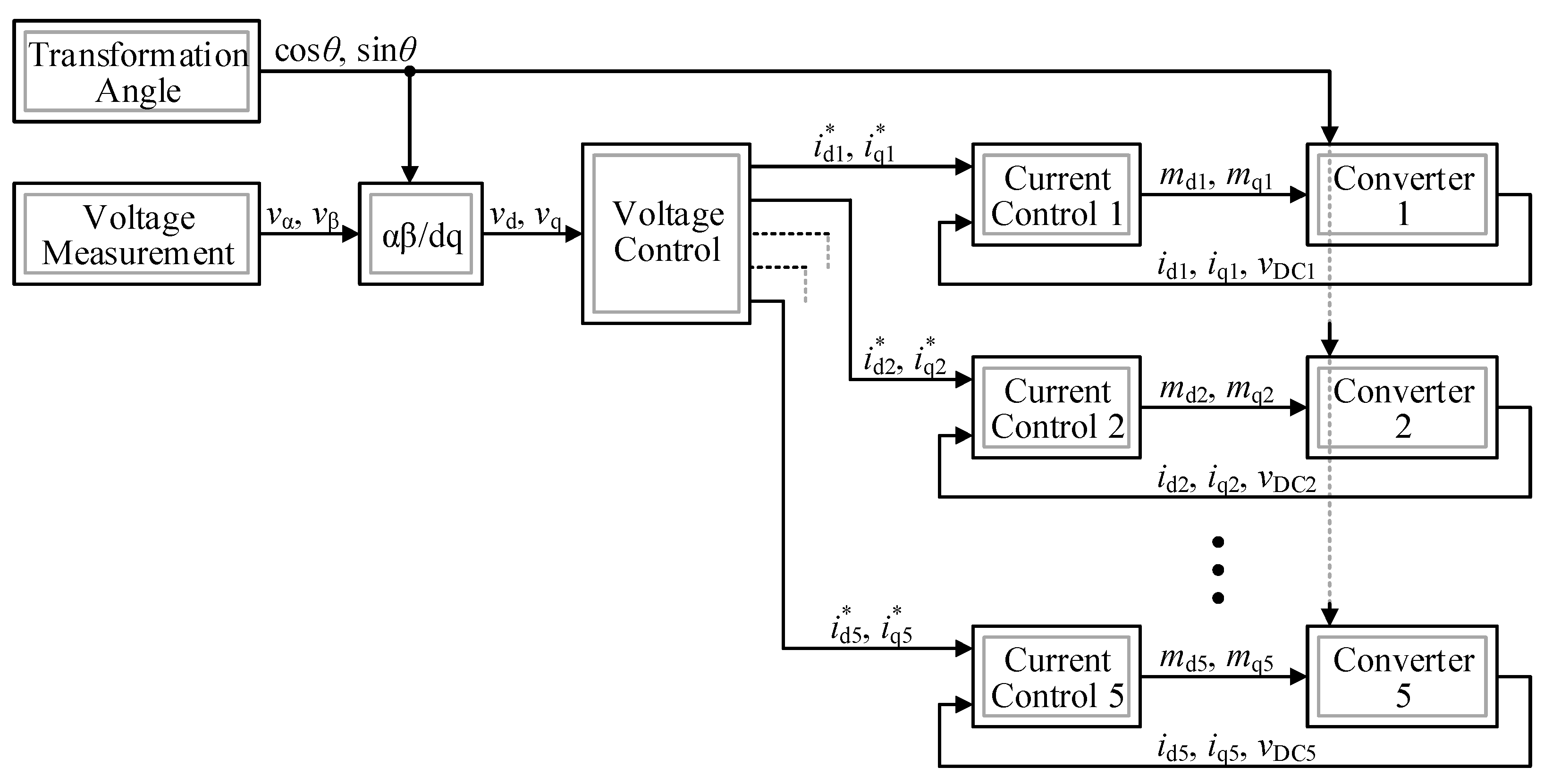
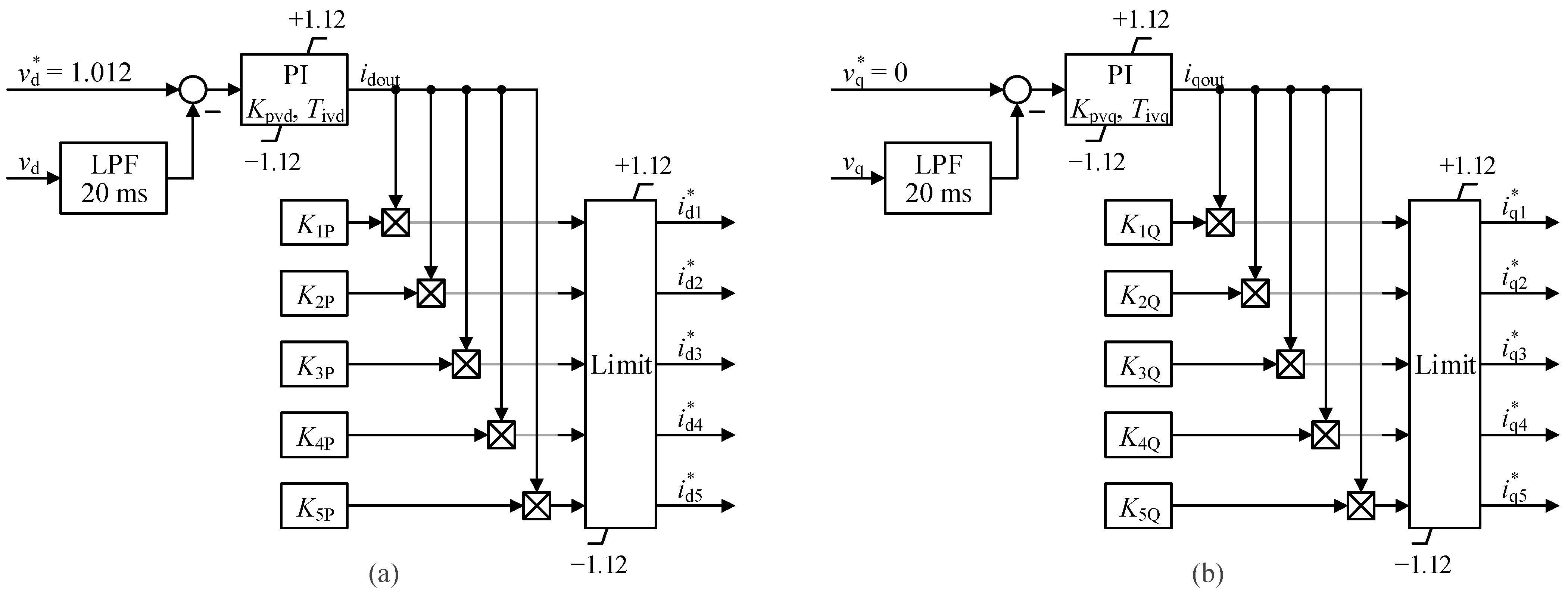
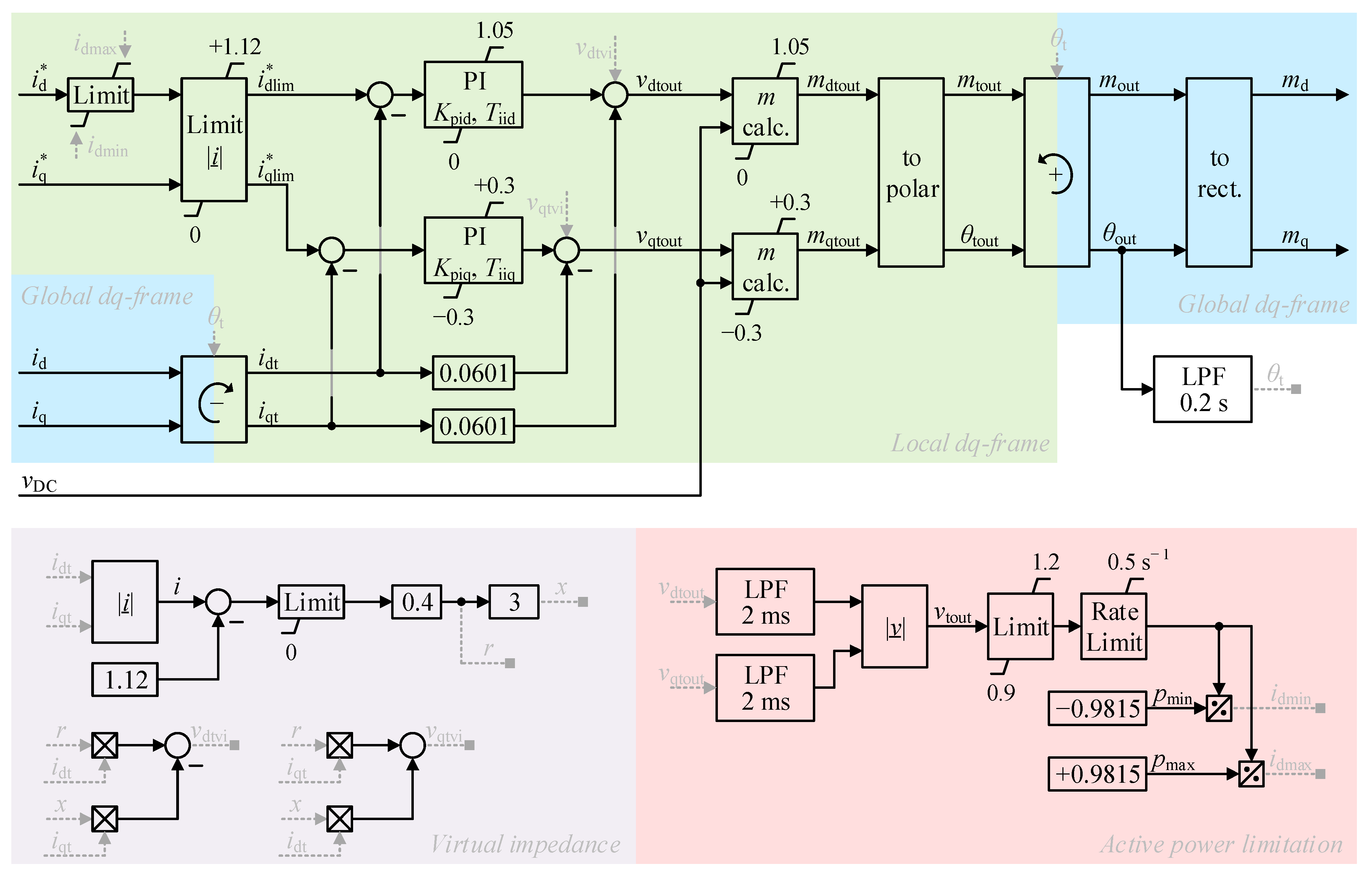
2.2. Offshore HVDC Converter Controls
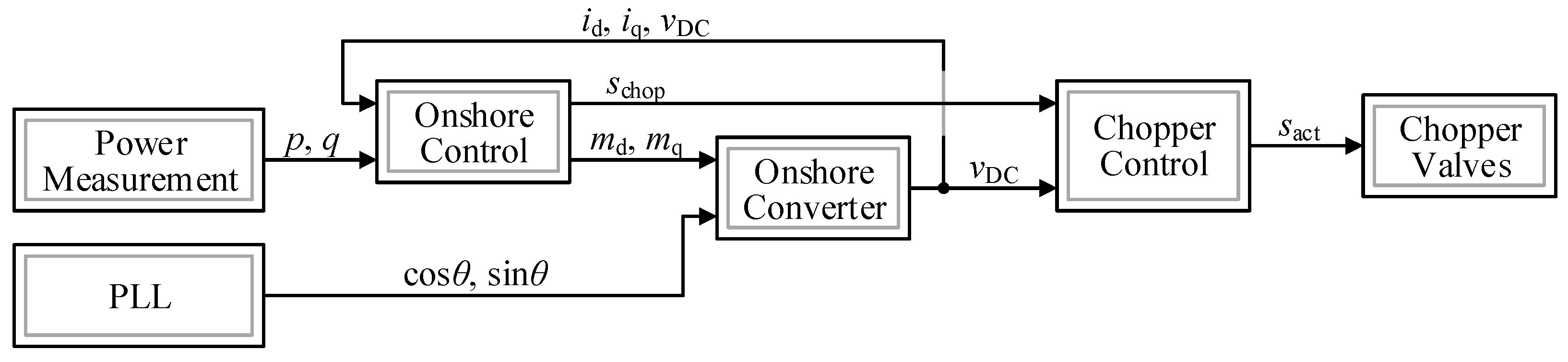
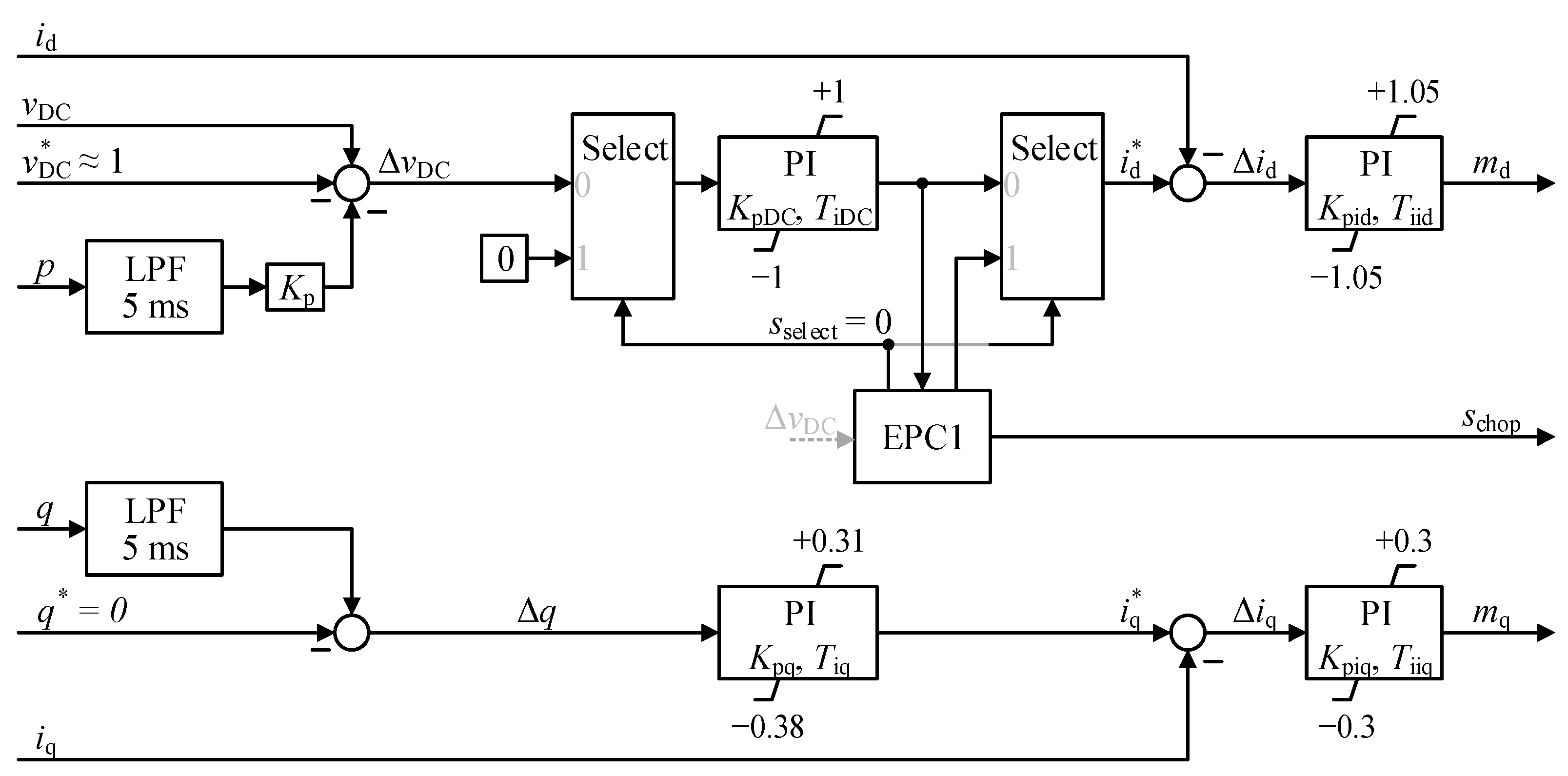
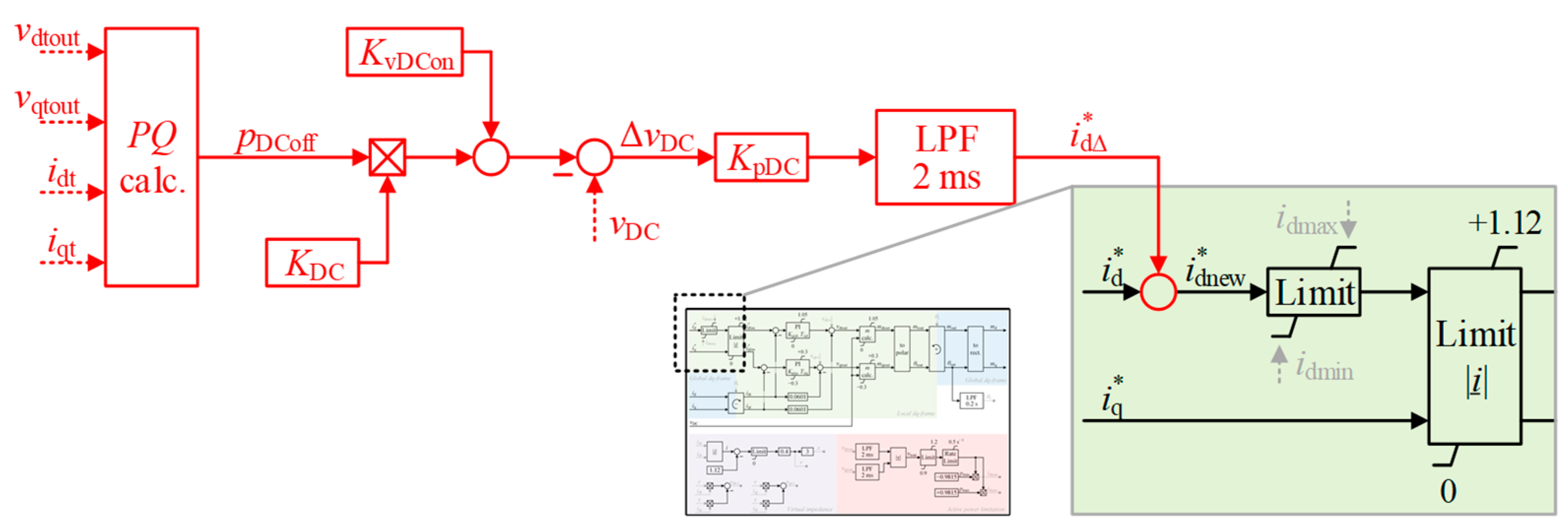
2.3. Onshore HVDC Converter Controls
3. Simplified Modeling of Onshore SI and PCR Contributions
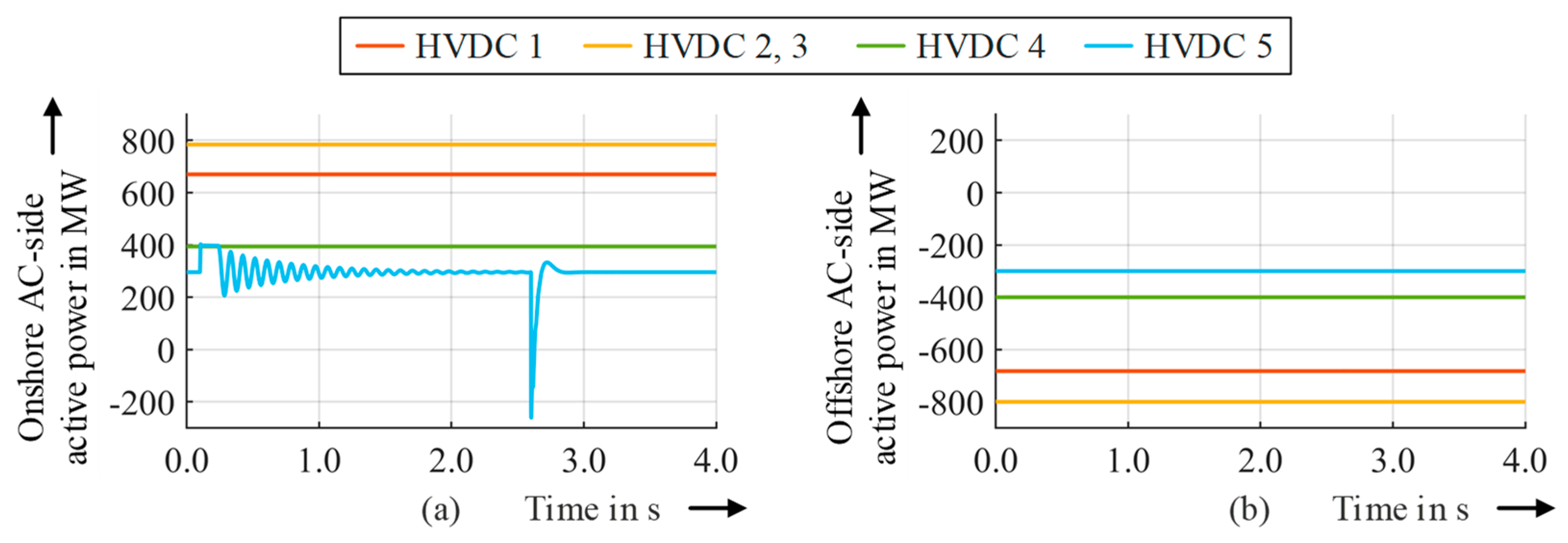
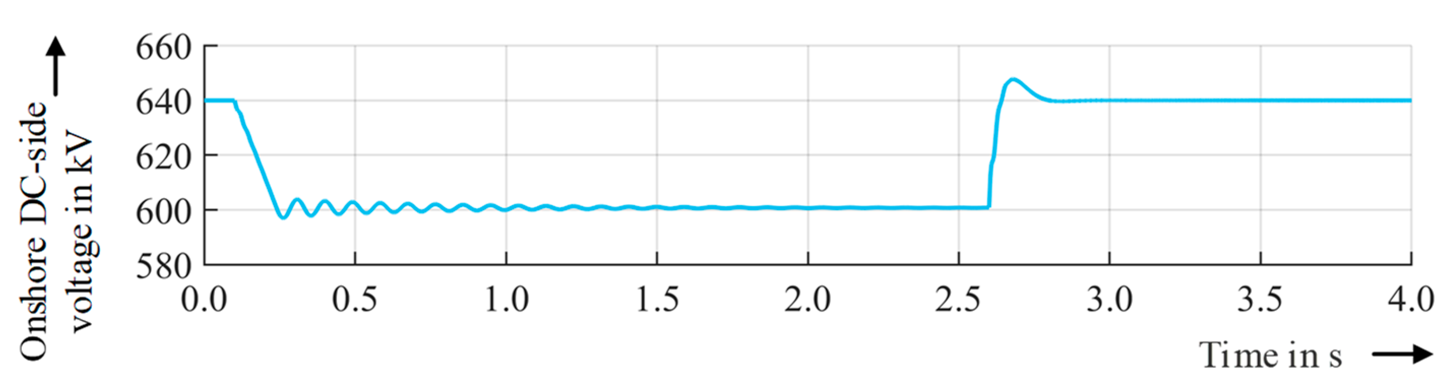
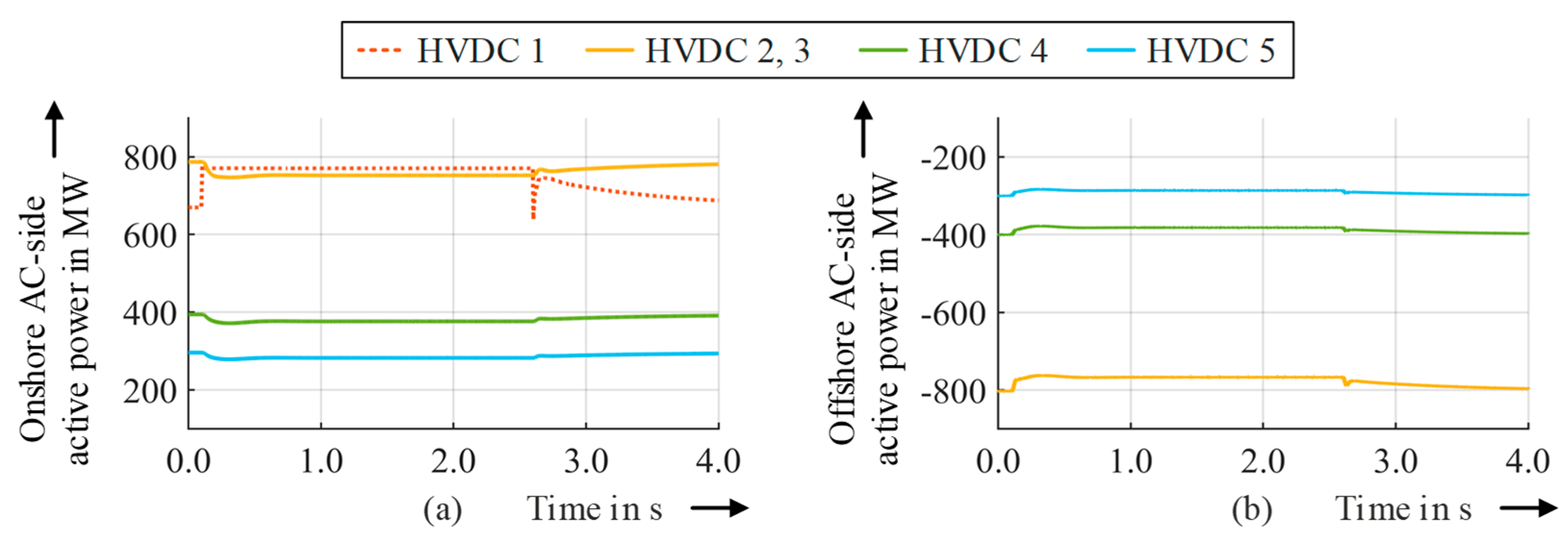
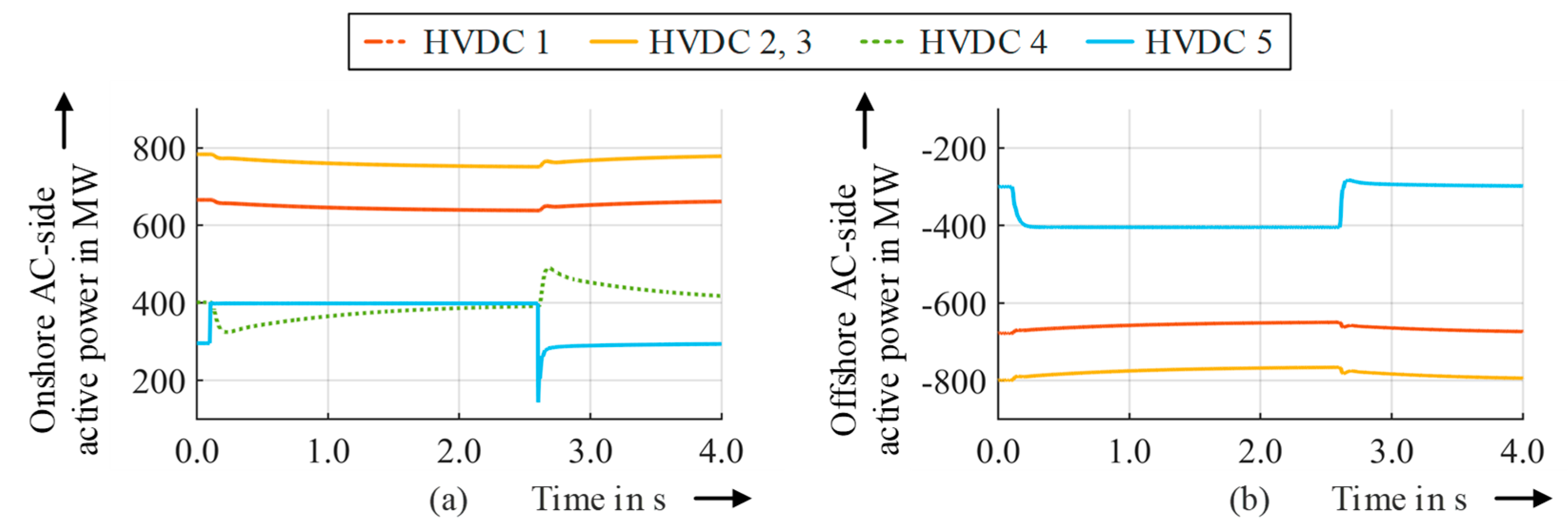
4. Feasibility and Effects of Onshore SI and PCR Contributions
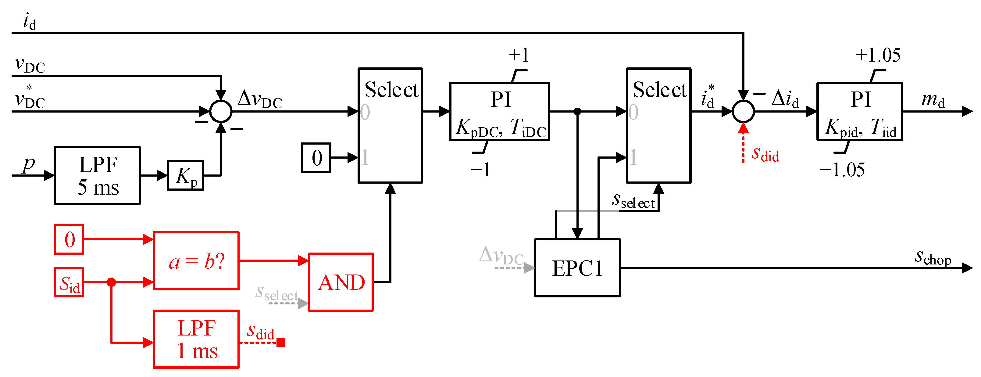
5. Enhancement of the Offshore HVDC Converter Controls
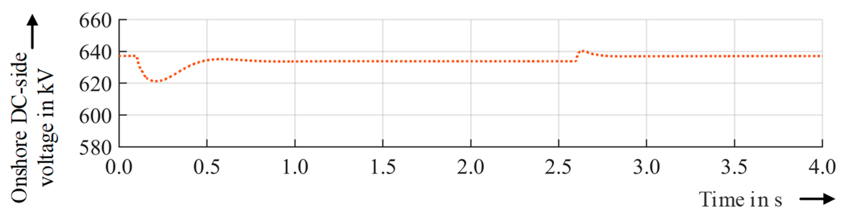
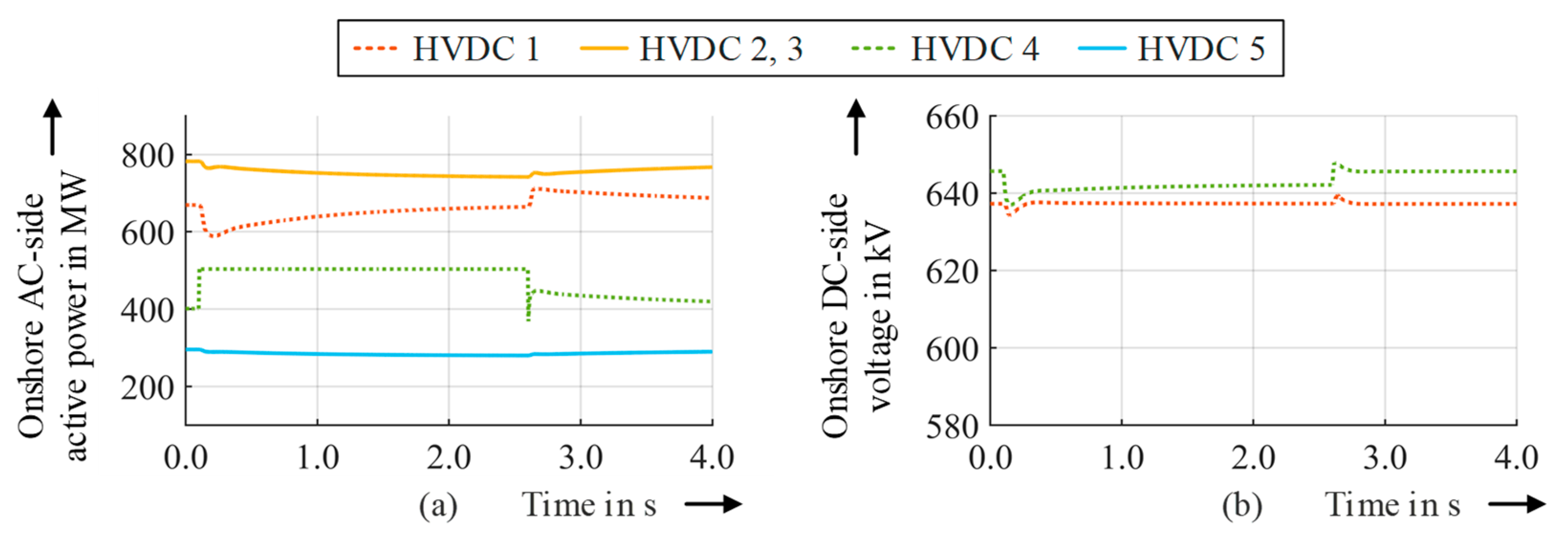
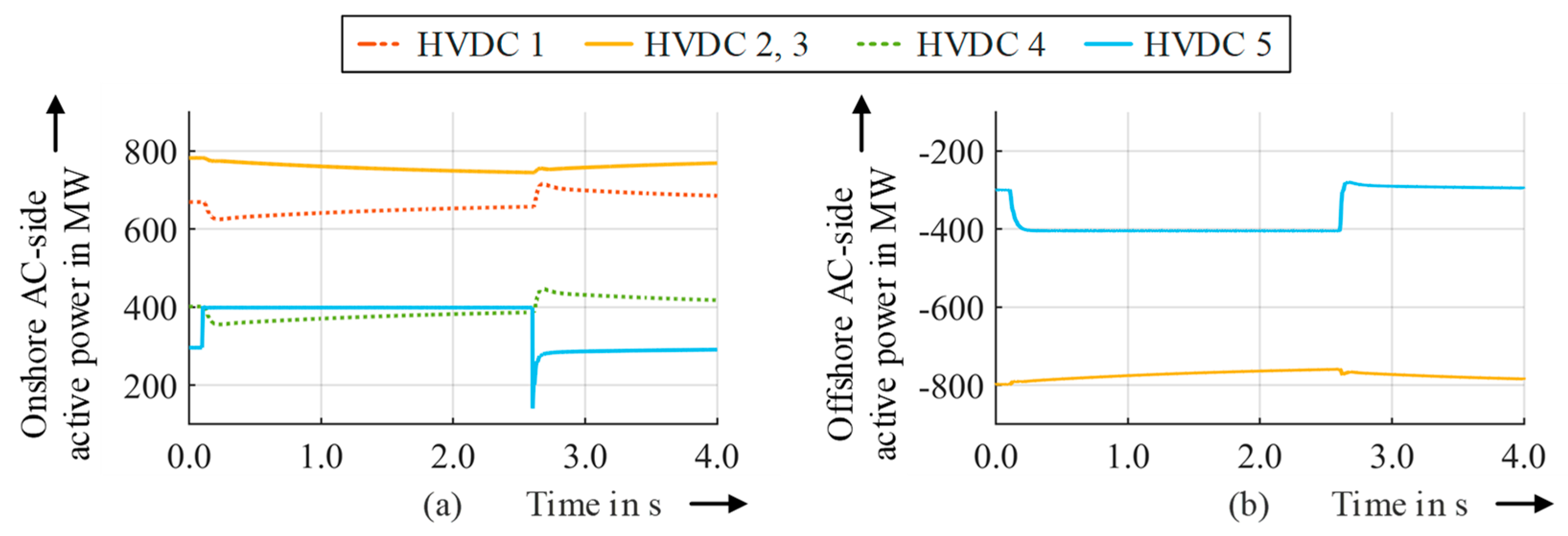
6. Feasibility and Effects of Onshore SI and PCR Contributions with the Enhanced Offshore HVDC Converter Controls
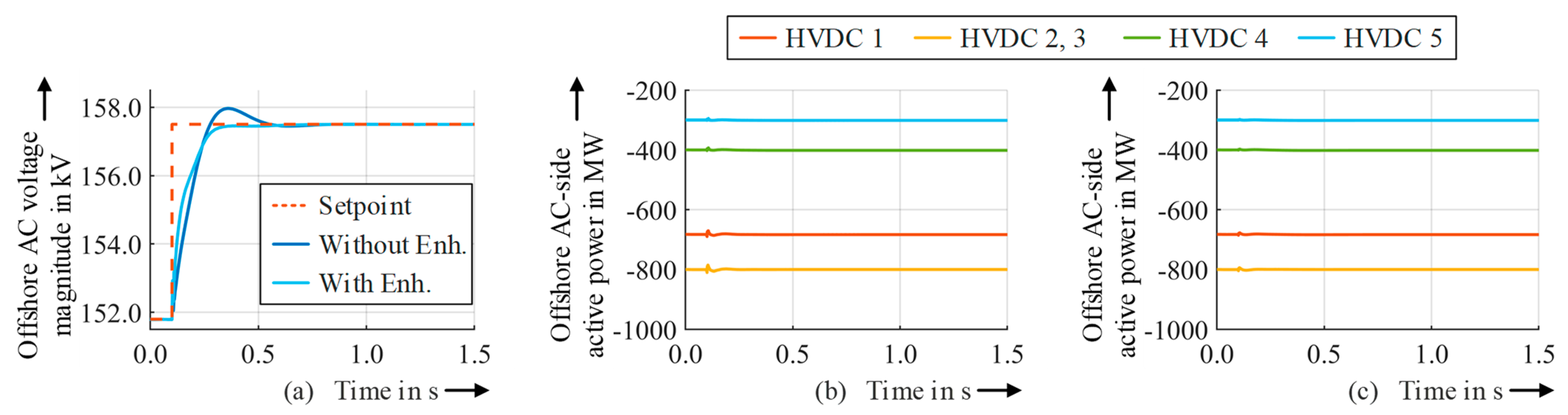
7. Effects of the Control Enhancement on Normal Operation and Fault Behavior
- Increase in the offshore AC voltage setpoint by 5.7 kV;
- Decrease in the offshore AC voltage setpoint by 5.7 kV;
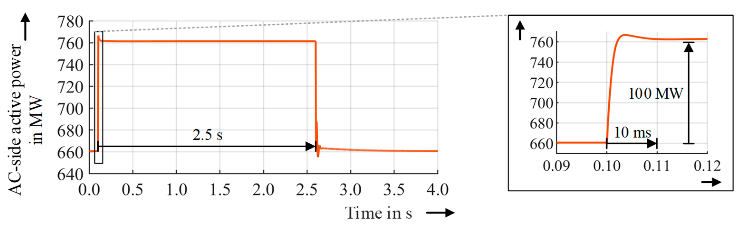
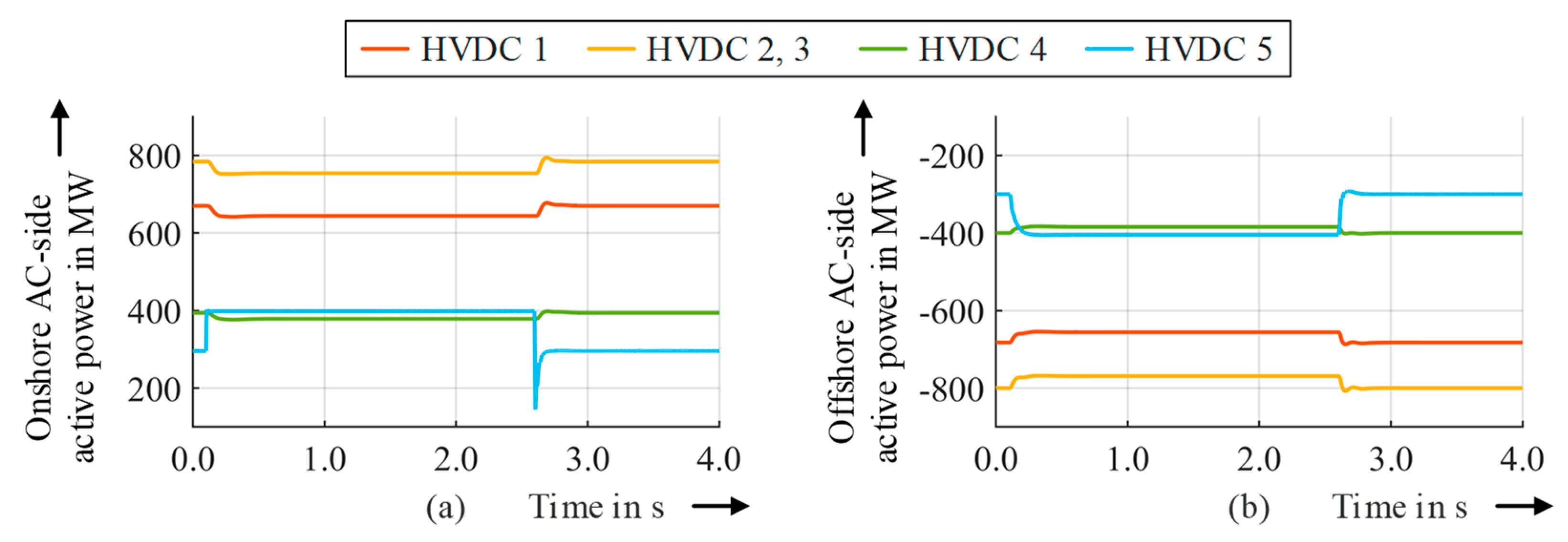
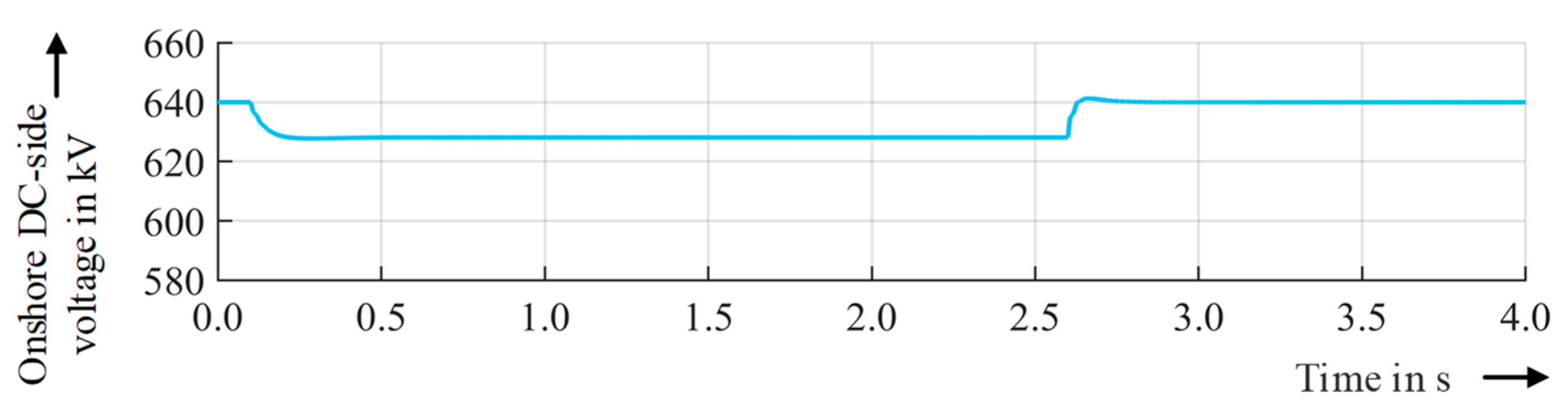
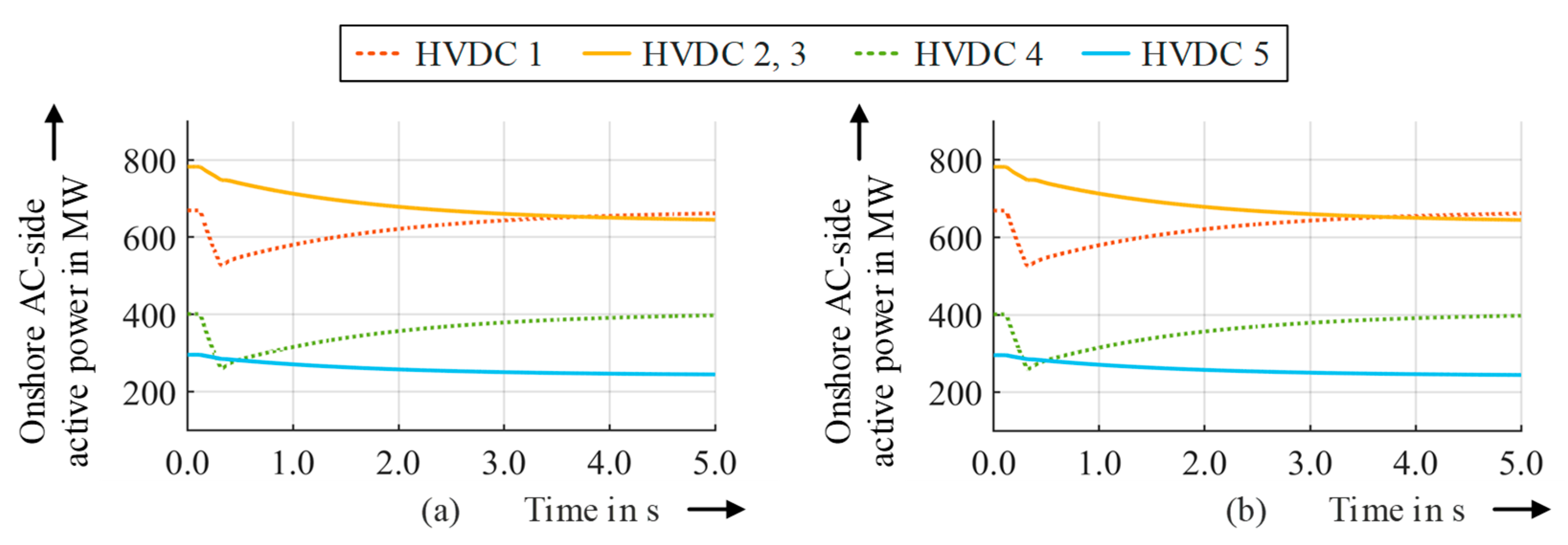
- Increase in the generation of OWP 2 by 360 MW within 200 ms;
- Decrease in the generation of OWP 2 by 360 MW within 200 ms;
- Tripping of OWP 4 at the GCP;
- Three-phase short circuit at node A for 150 ms;
- Three-phase short circuit in OWP 1 for 150 ms;
- Tripping of HVDC 2 at the AC side of the offshore converter;
- Tripping of one cable system between nodes A and C.
8. Conclusions and Outlook
Author Contributions
Funding
Data Availability Statement
Conflicts of Interest
References
- European Parliament. European Parliament Resolution of 15 January 2020 on the European Green Deal (2019/2956(RSP)); European Parliament: Strasbourg, France, 2020.
- European Parliament. Directive (EU) 2018/2001 of the European Parliament and of the Council of 11 December 2018 on the Promotion of the Use of Energy from Renewable Sources (Recast); European Parliament: Strasbourg, France, 2022.
- Breithaupt, T.; Herwig, D.; Hofmann, L.; Mertens, A.; Meyer, R.; Farrokhseresht, N.; Tuinema, B.; Wang, D.; Rueda Torres, J.; Rüberg, S.; et al. MIGRATE Deliverable 1.1: Report on Systemic Issues; MIGRATE Project Consortium: Bayreuth, Germany, 2016; Available online: https://www.h2020-migrate.eu/_Resources/Persistent/9bf78fc978e534f6393afb1f8510db86e56a1177/MIGRATE_D1.1_final_TenneT.pdf (accessed on 17 July 2023).
- Sewdien, V.N.; van der Meijden, M.; Breithaupt, T.; Hofmann, L.; Herwig, D.; Mertens, A.; Tuinema, B.; Rueda Torres, J.L. Effects of Increasing Power Electronics on System Stability: Results from MIGRATE Questionnaire. In Proceedings of the 2018 International Conference and Utility Exhibition on Green Energy for Sustainable Development (ICUE 2018), Phuket, Thailand, 24–26 October 2018; pp. 1–9. [Google Scholar]
- ENTSO-E. Frequency Stability Evaluation Criteria for the Synchronous Zone of Continental Europe; ENTSO-E RG-CE SP&D SG: Brussels, Belgium, 2016; Available online: https://eepublicdownloads.entsoe.eu/clean-documents/SOC%20documents/RGCE_SPD_frequency_stability_criteria_v10.pdf (accessed on 17 July 2023).
- RE-SERVE Project Website. Available online: http://www.re-serve.eu/ (accessed on 17 July 2023).
- MIGRATE Project Website. Available online: https://www.h2020-migrate.eu/ (accessed on 17 July 2023).
- European Parliament. European Parliament Resolution of 16 February 2022 on a European Strategy for Offshore Renewable Energy (2021/2012(INI)); European Parliament: Strasbourg, France, 2022.
- Federal Ministry for Economic Affairs and Climate Action. Ostend Declaration of Energy Ministers on the North Seas as Europe’s Green Power Plant; BMWK: Berlin, Germany, 2023; Available online: https://www.bmwk.de/Redaktion/DE/Downloads/Energie/ostend-declaration-energy-ministers-north-seas-europes-green-power-plant.pdf (accessed on 17 July 2023).
- ENTSO-E. ENTSO-E Position on Offshore Development; ENTSO-E AISBL: Brussels, Belgium, 2020; Available online: https://eepublicdownloads.azureedge.net/clean-documents/Publications/Position%20papers%20and%20reports/2021/entso-e_pp_Offshore_Development_01_200528.pdf (accessed on 17 July 2023).
- Mende, D.; Harms, Y.; Härtel, P.; Frischmuth, F.; Stock, D.S.; Braun, M.; Herrmann, M.; Hofmann, L.; Valois, M.; Bley, A.; et al. NSON II: Next Steps in Economical Connection and International Integration of Offshore Wind Energy in the North Seas. In Proceedings of the 19th International Workshop on Large-Scale Integration of Wind Power into Power Systems as Well as on Transmission Networks for Offshore Wind Power Plants, Online, 11–12 November 2020; ISBN 9783982008080. [Google Scholar]
- Scheufeld, O.; Audichya, Y.; Menze, S.; Wagner, A.; de Groot, N.; Antoine, O.; Henneaux, P.; Karoui, K.; Lessinnes, M.; Mannocchi, A.; et al. PROMOTioN Deliverable 1.6: Draft Roadmap and Reference Offshore Grid Expansion Plan; PROMOTioN Project Consortium: Arnhem, The Netherlands, 2017; Available online: https://www.promotion-offshore.net/fileadmin/PDFs/D1.6_Draft_r.oadmap_and_reference_offshore_grid_expansion_plan_-_v1.0.pdf (accessed on 17 July 2023).
- Nouri, B.; Sørensen, P.; Rudolph, F.; Brantl, C.; Köhler, H.; Adam, G.P.; Li, R.; Bernal-Perez, S. PROMOTioN Deliverable 2.4: Requirement Recommendations to Adapt and Extend Existing Grid Codes; PROMOTioN Project Consortium: Arnhem, The Netherlands, 2019; Available online: https://www.promotion-offshore.net/fileadmin/PDFs/D2.4_Requirement_recommendations_to_adapt_.and_extend_existing_grid_codes_final.pdf (accessed on 17 July 2023).
- Hammer, T.; Slavomir, S.; Menke, P.; Hacker, F.; Szangolies, B.; Meth, J.; Dorn, J.; Loppach, K.; Zurowski, R. Diode-Rectifier HVDC Link to Onshore Power Systems: Dynamic Performance of Wind Turbine Generators and Reliability of Liquid Immersed HVDC Diode Rectifier Units; CIGRÉ: Paris, France, 2016. [Google Scholar]
- Kuhn, O.; Menke, P.; Zurowski, R.; Christ, T.; Seman, S.; Giering, G.; Hammer, T.; Imamovic, D.; Thisted, J.; Brogn, P.; et al. 2nd Generation DC Grid Access for Offshore Wind Farms: HVDC in an AC Fashion; CIGRÉ: Paris, France, 2016. [Google Scholar]
- Menke, P. 2nd Generation DC Grid Access for Large Scale Offshore Wind Farms. In Proceedings of the Offshore Wind R&D Conference 2015, Bremerhaven, Germany, 13–15 October 2015. [Google Scholar]
- PROMOTioN Project Website. Available online: https://www.promotion-offshore.net/ (accessed on 17 July 2023).
- NSON II Project Website. Available online: https://www.iee.fraunhofer.de/en/research_projects/search/2020/nson-2.html (accessed on 17 July 2023).
- Henninger, S.; Jaeger, J. Advanced classification of converter control concepts for integration in electrical power systems. Int. J. Electr. Power Energy Syst. 2020, 123, 106210. [Google Scholar] [CrossRef]
- North American Electric Reliability Corporation. Fast Frequency Response Concepts and Bulk Power System Reliability Needs; NERC: Atlanta, GA, USA, 2020. [Google Scholar]
- Rüberg, S.; Sewdien, V.; Rueda Torres, J.L.; Rakhshani, E.; Wang, D.; Tuinema, B.; Farrokhseresht, N.; Gusain, D.; Perilla, A.; Mola Jimenez, J.; et al. MIGRATE Deliverable 1.6: Demonstration of Mitigation Measures and Clarification of Unclear Grid Code Requirements; MIGRATE Project Consortium: Bayreuth, Germany, 2019; Available online: https://www.h2020-migrate.eu/_Resources/Persistent/a7e3d4424f6f749e419ddac011419e7a0aa5f576/D1.6%20-%20Demonstration%20of%20Mitigation%20Measures%20and%20Clarification%20of%20Unclear%20Grid%20Code%20Requirements%20-%20final.pdf (accessed on 17 July 2023).
- European Commission. Commission Regulation (EU) 2016/1447 of 26 August 2016 Establishing a Network Code on Requirements for Grid Connection of High Voltage Direct Current Systems and Direct Current-Connected Power Park Modules; European Commission: Brussels, Belgium, 2016.
- TenneT TSO GmbH. Netzanschlussregeln: Hoch- und Höchstspannung; TenneT TSO GmbH: Bayreuth, Germany, 2022; Available online: https://www.tennet.eu/de/strommarkt/kunden-deutschland/netzkunden/netzanschlussregeln (accessed on 17 July 2023).
- Verband der Elektrotechnik, Elektronik, Informationstechnik e. V. VDE-AR-N 4131, Technische Regeln für den Anschluss von HGÜ-Systemen und über HGÜ-Systeme Angeschlossene Erzeugungsanlagen (TAR HGÜ); VDE Verlag GmbH: Berlin, Germany, 2019; Available online: https://www.vde-verlag.de/normen/0100511/vde-ar-n-4131-anwendungsregel-2019-03.html (accessed on 17 July 2023).
- Zhu, J.; Booth, C.D.; Adam, G.P.; Roscoe, A.J.; Bright, C.G. Inertia Emulation Control Strategy for VSC-HVDC Transmission Systems. IEEE Trans. Power Syst. 2013, 28, 1277–1287. [Google Scholar] [CrossRef]
- Zhang, Z.; Lee, J.; Jang, G. Improved Control Strategy of MMC–HVDC to Improve Frequency Support of AC System. Appl. Sci. 2020, 10, 7282. [Google Scholar] [CrossRef]
- Wang, Y.; Zhu, X.; Xu, L.; Li, H. Contribution of VSC-HVDC connected wind farms to grid frequency regulation and power damping. In Proceedings of the 36th Annual Conference of the IEEE Industrial Electronics Society (IECON 2010), Glendale, AZ, USA, 7–10 November 2010; pp. 397–402. [Google Scholar]
- Liu, X.; Lindemann, A. Control of VSC-HVDC Connected Offshore Windfarms for Providing Synthetic Inertia. IEEE J. Emerg. Sel. 2018, 6, 1407–1417. [Google Scholar] [CrossRef]
- Pipelzadeh, Y.; Chaudhuri, B.; Green, T.C. Inertial response from remote offshore wind farms connected through VSC-HVDC links: A Communication-less scheme. In Proceedings of the 2012 IEEE Power and Energy Society General Meeting, San Diego, CA, USA, 22–26 July 2012; pp. 1–6. [Google Scholar]
- Li, Y.; Zhang, Z.; Yang, Y.; Li, Y.; Chen, H.; Xu, Z. Coordinated control of wind farm and VSC–HVDC system using capacitor energy and kinetic energy to improve inertia level of power systems. Int. J. Electr. Power Energy Syst. 2014, 59, 79–92. [Google Scholar] [CrossRef]
- Junyent-Ferre, A.; Pipelzadeh, Y.; Green, T.C. Blending HVDC-Link Energy Storage and Offshore Wind Turbine Inertia for Fast Frequency Response. IEEE Trans. Sustain. Energy 2015, 6, 1059–1066. [Google Scholar] [CrossRef]
- Wen, L.; Sun, Z.; Hu, H.; Zhang, Y.; Lu, G.; Wu, J.; Dou, Q. A novel frequency support strategy for VSC-HVDC system with large wind power integration. In Proceedings of the 18th International Conference on AC and DC Power Transmission (ACDC 2022), Online Conference, 2–3 July 2022; pp. 666–670. [Google Scholar]
- Chu, J.; Lv, Y.; Xu, Y.; Du, G.; Sun, D.; Yu, P. Coordinated Control Strategy for Improving Frequency Stability of Offshore Wind Farms Connected to the Grid through MMC-HVDC Transmission. In Proceedings of the 4th Asia Energy and Electrical Engineering Symposium (AEEES 2022), Chengdu, China, 25–28 March 2022; pp. 354–360. [Google Scholar]
- Phulpin, Y. Communication-Free Inertia and Frequency Control for Wind Generators Connected by an HVDC-Link. IEEE Trans. Power Syst. 2012, 27, 1136–1137. [Google Scholar] [CrossRef]
- Lin, C.-H.; Wu, Y.-K. Overview of Frequency-Control Technologies for a VSC-HVDC-Integrated Wind Farm. IEEE Access 2021, 9, 112893–112921. [Google Scholar] [CrossRef]
- Wu, J.; Wang, Z.; Rao, H.; Chen, Y.; Huang, W. A Review of Control Strategies for Inertia Support in VSC-HVDC System. In Proceedings of the 4th IEEE Workshop on the Electronic Grid (eGRID 2019), Xiamen, China, 11–14 November 2019; pp. 1–6. [Google Scholar]
- Zhang, H.; Zhu, J.; Guerrero, J.M.; Adam, G.P.; Booth, C.D. A generic inertia emulation controller for multi-terminal VSC-HVDC systems. In Proceedings of the 2nd IET Renewable Power Generation Conference (RPG 2013), Beijing, China, 9–11 September 2013. [Google Scholar]
- Bidadfar, A.; Saborío-Romano, O.; Sakamuri, J.N.; Altin, M.; Cutululis, N.A.; Sørensen, P.E. Primary Frequency Support from Offshore Wind Power Plants Connected to HVDC Grids. In Proceedings of the 2019 IEEE Milan PowerTech, Milano, Italy, 23–27 June 2019; pp. 1–6. [Google Scholar]
- Tu, L.; Yang, Y.; Yang, J.; Sun, T. The Synthetic Inertia Controller for MMC-HVDC Based Offshore Wind Farm Integration. In Proceedings of the IEEE 1st International Power Electronics and Application Symposium (PEAS 2021), Shanghai, China, 12–15 November 2021; pp. 1–4. [Google Scholar]
- Silva, B.; Moreira, C.L.; Seca, L.; Phulpin, Y.; Pecas Lopes, J.A. Provision of Inertial and Primary Frequency Control Services Using Offshore Multiterminal HVDC Networks. IEEE Trans. Sustain. Energy 2012, 3, 800–808. [Google Scholar] [CrossRef]
- Adeuyi, O.D.; Cheah-Mane, M.; Liang, J.; Jenkins, N. Fast Frequency Response From Offshore Multiterminal VSC–HVDC Schemes. IEEE Trans. Power Deliv. 2017, 32, 2442–2452. [Google Scholar] [CrossRef]
- Saborío-Romano, O.; Bidadfar, A.; Sakamuri, J.N.; Göksu, Ö.; Cutululis, N.A. Primary Frequency Response from Offshore Wind Farms Connected to HVdc via Diode Rectifiers. In Proceedings of the 2019 IEEE Milan PowerTech, Milano, Italy, 23–27 June 2019; pp. 1–6. [Google Scholar]
- Saborío-Romano, O. PROMOTioN Deliverable 3.5: Performance of Ancillary Services Provision from WFs Connected to DR-HVDC; PROMOTioN Project Consortium: Arnhem, The Netherlands, 2018; Available online: https://www.promotion-offshore.net/fileadmi.n/PDFs/D3.5_PROMOTioN_Performance_of_ancillary_services_pro-vision_from_WFs_connected_to_DR-HVDC.pdf (accessed on 17 July 2023).
- Xiao, H.; Huang, X.; Huang, Y.; Liu, Y. Self-Synchronizing Control and Frequency Response of Offshore Wind Farms Connected to Diode Rectifier Based HVDC System. IEEE Trans. Sustain. Energy 2022, 13, 1681–1692. [Google Scholar] [CrossRef]
- Xie, L.; Yao, L.; Li, Y.; Xu, L.; Wang, Z.; Wei, C.; Fan, C. Frequency regulation participation of offshore wind farm integrated by diode-rectifer HVDC system. J. Eng. 2019, 2019, 977–981. [Google Scholar] [CrossRef]
- Saborío-Romano, O.; Bidadfar, A.; Sakamuri, J.N.; Zeni, L.; Göksu, Ö.; Cutululis, N.A. Communication-Less Frequency Support From Offshore Wind Farms Connected to HVdc via Diode Rectifiers. IEEE Trans. Sustain. Energy 2021, 12, 441–450. [Google Scholar] [CrossRef]
- Saborío-Romano, O.; Bidadfar, A.; Sakamuri, J.N.; Göksu, Ö.; Cutululis, N.A. Fast Frequency Response from Offshore Wind Farms Connected to HVDC via Diode Rectifiers. In Proceedings of the 2019 CIGRÉ Aalborg International Symposium, Aalborg, Denmark, 4–7 June 2019. [Google Scholar]
- Herrmann, M. Dataset: PowerFactory EMT Model of a Meshed AC Offshore Wind Park Grid Connected by Five HVDC Connections; Leibniz University Hannover: Hanover, Germany, 2023. [Google Scholar] [CrossRef]
- Herrmann, M.; Hofmann, L. AP 2: Anlagen- und Systemregelung AS 2.2: Entwicklung von Regelungskonzepten zum Parallelbetrieb von HGÜ-Umrichterstationen; NSON II Project Consortium: Kassel, Germany, 2021; Available online: https://publica.fraunhofer.de/entities/publication/e0ed1845-19c8-41e1-bdde-08608591c684/details (accessed on 17 July 2023).
- Herrmann, M.; Hofmann, L. AP 2: Anlagen- und Systemregelung AS 2.3: Entwicklung von Regelungskonzepten zum Betrieb von HGÜ-Umrichterstationen in Drehstromseitig Vermaschten Offshore-Netzen; NSON II Project Consortium: Kassel, Germany, 2022; Available online: https://publica.fraunhofer.de/entities/publication/611c3204-57df-467c-80f0-90b36b1f006b/details (accessed on 17 July 2023).
- Korai, A.W. Dynamic Performance of Electrical Power Systems with High Penetration of Power Electronic Converters: Analysis and New Control Methods for Mitigation of Instability Threats and Restoration. Doctoral Thesis, Universität Duisburg-Essen, Duisburg, Essen, Germany, 2019. [Google Scholar]
- TenneT TSO GmbH. Offshore-Netzanschlussregeln; TenneT TSO GmbH: Bayreuth, Germany, 2019. [Google Scholar]
- Weber, H.; Baskar, P.; Ahmed, N. Power system control with renewable sources, storages and power electronic converters. In Proceedings of the 2018 IEEE International Conference on Industrial Technology (ICIT 2018), Lyon, France, 20–22 February 2018; pp. 1272–1278. [Google Scholar]
- Herrmann, M.; Hofmann, L. Enhancement of a Control Concept for Parallel HVDC Link Operation to Increase Flexibility for Offshore Wind Park Grid Connections. In Proceedings of the 12th International Renewable Energy Congress (IREC 2021), Hammamet, Tunisia, 26–28 October 2021; pp. 1–8. [Google Scholar]
- Lopez, M.; Briz, F.; Zapico, A.; Diaz-Reigosa, D.; Guerrero, J.M. Operation of modular multilevel converters under voltage constraints. In Proceedings of the 2015 IEEE Energy Conversion Congress and Exposition (ECCE 2015), Montreal, QC, Canada, 20–24 September 2015; pp. 3550–3556. [Google Scholar]
- Qoria, T.; Cossart, Q.; Li, C.; Guillaud, X.; Colas, F.; Gruson, F.; Kestelyn, X. MIGRATE Deliverable 3.2: Local Control and Simulation Tools for Large Transmission Systems; MIGRATE Project Consortium: Bayreuth, Germany, 2018; Available online: https://www.h2020-migrate.eu/_Resources/Persistent/5c5beff0d5bef78799253aae9b19f50a9cb6eb9f/D3.2%20-%20Local%20control%20and%20simulation%20tools%20for%20large%20transmission%20systems.pdf (accessed on 17 July 2023).
- DIgSILENT GmbH. Technical Reference Documentation Phase Measurement Device: ElmPhi_pll; DIgSILENT GmbH: Gomaringen, Germany, 2019. [Google Scholar]


| Parameter | Offshore HVDC Converter | Onshore HVDC Converter |
|---|---|---|
| Sr | 917 MVA | 971.2 MVA |
| Pr, Qr | 900 MW, ±127 Mvar | 900 MW, +365/−293 Mvar |
| VrAC, VrDC | 363 kV AC, ±320 kV DC | 380 kV AC, ±320 kV DC |
| Larm, Rarm | 55 mH, 5.5 mΩ | 55 mH, 5.5 mΩ |
| NSM, CSM | 230 (per arm), 11 mF | 235 (per arm), 11 mF |
| Parameter | R’ (20 °C) | L’ | G’ | C’ |
|---|---|---|---|---|
| Value | 12.9 mΩ/km | 157 nH/km | 0 μS/km | 226 nF/km |
| Parameter | Value | Parameter | Value |
|---|---|---|---|
| Kpvd | 0.2 | Kpvq | 30 |
| Tivd | 0.15 s | Tivq | 0.15 s |
| Parameter | Value | Parameter | Value |
|---|---|---|---|
| Kpid | 0.8 | Kpiq | 0.8 |
| Tiid | 10 ms | Tiiq | 10 ms |
| Parameter | Value | Parameter | Value |
|---|---|---|---|
| KpDC | 10 | Kpq | 5 |
| TiDC | 5 ms | Tiq | 100 s |
| Kpid | 2 | Kpiq | 2 |
| Tiid | 2 ms | Tiiq | 2 ms |
| Kp | 0.01 1 |
| Grid Model Variant | DRU HVDC Connections | OWP | Generation 1 | HVDC | Transmission 2 |
|---|---|---|---|---|---|
| Variant 1 | none | OWP 1 | 180 MW | HVDC 1 | −682 MW |
| Variant 2 | HVDC 1 | OWP 2 | 1440 MW | HVDC 2 | −800 MW |
| Variant 3 | HVDC 4 | OWP 3 | 180 MW | HVDC 3 | −800 MW |
| Variant 4 | HVDC 1, 4 | OWP 4 | 720 MW | HVDC 4 | −400 MW |
| OWP 5 | 180 MW | HVDC 5 | −300 MW | ||
| OWP 6 | 360 MW |
Disclaimer/Publisher’s Note: The statements, opinions and data contained in all publications are solely those of the individual author(s) and contributor(s) and not of MDPI and/or the editor(s). MDPI and/or the editor(s) disclaim responsibility for any injury to people or property resulting from any ideas, methods, instructions or products referred to in the content. |
© 2023 by the authors. Licensee MDPI, Basel, Switzerland. This article is an open access article distributed under the terms and conditions of the Creative Commons Attribution (CC BY) license (https://creativecommons.org/licenses/by/4.0/).
Share and Cite
Herrmann, M.; Alkemper, M.; Hofmann, L. Analysis of Onshore Synthetic Inertia and Primary Control Reserve Contributions of Alternating Current-Side Meshed Offshore Grids with Voltage-Source Converter and Diode Rectifier Unit High-Voltage Direct Current Connections. Energies 2023, 16, 6700. https://doi.org/10.3390/en16186700
Herrmann M, Alkemper M, Hofmann L. Analysis of Onshore Synthetic Inertia and Primary Control Reserve Contributions of Alternating Current-Side Meshed Offshore Grids with Voltage-Source Converter and Diode Rectifier Unit High-Voltage Direct Current Connections. Energies. 2023; 16(18):6700. https://doi.org/10.3390/en16186700
Chicago/Turabian StyleHerrmann, Michael, Merlin Alkemper, and Lutz Hofmann. 2023. "Analysis of Onshore Synthetic Inertia and Primary Control Reserve Contributions of Alternating Current-Side Meshed Offshore Grids with Voltage-Source Converter and Diode Rectifier Unit High-Voltage Direct Current Connections" Energies 16, no. 18: 6700. https://doi.org/10.3390/en16186700