1. Introduction
Perovskite materials show superior photovoltaic properties, including long exciton diffusion length, and controllable band gap [
1,
2,
3,
4,
5]. The power conversion efficiency (PCE) of perovskite solar cells (PSCs) significantly increased to 25.7% since perovskite materials were introduced in 2009 to prepare solar cells [
6]. In contrast to conventional silicon-based solar cells, PSCs are cheaper and easier to manufacture. These benefits increase the potential of PSCs [
7,
8,
9]. PSCs can be divided into all-inorganic perovskite solar cells and organic–inorganic hybrid perovskite solar cells. Although organic–inorganic hybrid PSCs exhibit excellent PCE, their commercial development is hampered by poor humidity and temperature stability [
10].
In contrast to organic–inorganic hybrid PSCs, CsPbX
3 all-inorganic PSCs using the inorganic metal cation Cs
+ instead of the A
− position organic cation group have received more attention due to the better humidity and temperature stability [
11,
12]. The efficiency of CsPbI
3 PSCs was almost the same as that of organic–inorganic hybrid PSCs [
13]. However, CsPbI
3 crystals will rapidly convert from α-phase to δ-phase and lose their photovoltaic capacity when exposed to ambient temperature [
14,
15]. In order to make CsPbI
3 crystals more stable and prevent phase transitions, Br element was integrated into the CsPbI
3 film to prepare CsPbI
2Br PSCs. CsPbI
2Br solar cells have a maximum efficiency of 17.46%, but their stability is still low [
16]. CsPbBr
3 PSCs have better humidity and thermal stability compared with CsPbI
3 and CsPbI
2Br PSCs, and they maintain their original PCE of over 800 h after being exposed to the air [
17]. Moreover, CsPbBr
3 PSCs can theoretically produce an open-circuit voltage (
Voc) of above 2.0 V owing to its large band gap. A high
Voc enables CsPbBr
3 cells to be used in stacked solar cell modules and increases the potential applications.
In general, it is difficult to fabricate CsPbBr
3 film via the traditional one-step spin-coating method because of the significant difference in solubility between PbBr
2 and CsBr in a frequently used solvent [
18]. At present, most CsPbBr
3 films are prepared using the multi-step spin-coating method. In the multi-step spin-coating method, 1 M PbBr
2/DMF solution is firstly deposited on the substrate to form a PbBr
2 film, followed by spin-coating of 0.07 M CsBr/methanol solution on the deposited PbBr
2 film multiple times owing to the low solubility of CsBr in methanol to form orange-phase CsPbBr
3 film [
19]. The multi-step spin-coating is able to regulate the degree of reaction between PbBr
2 and CsBr and create high phase-purity CsPbBr
3 films [
20,
21,
22]. In contrast, the multi-step spin-coating method is laborious and time-consuming. Furthermore, the excessive use of methanol is harmful to the environment and has a large negative impact on researchers’ ideas, which greatly affects the sustainable development of CsPbBr
3 PSCs. Therefore, it is highly essential to exploit a facile solution treatment strategy to prepare high-quality CsPbBr
3 films with as few toxic solvents as possible.
Water can effectively dissolve CsBr but can only poorly dissolve PbBr
2. Based on the enormous solubility of CsBr in water, Wan’s group adopted the CsBr methanol/H
2O solution (methanol:H
2O = 5:1) and isopropanol-assisted post-treatment to prepare CsPbBr
3 PSCs via a two-step spin-coating method [
23]. This significantly reduced the use of methanol, but did not remove it. The CsBr methanol/H
2O solution is still toxic. Wei’s group used water as the solvent of CsBr to fabricate CsPbBr
3 PSCs at an efficiency of 6.12%, making it possible to use the two-step spin-coating method to prepare CsPbBr
3 PSCs without using methanol [
24]. However, there are several disadvantages to utilizing water as the solvent of CsBr. First, the CsBr/H
2O solution is unable to propagate uniformly on the PbBr
2 film due to the poor wettability of PbBr
2 film and water can dissolve the CsPbBr
3 film, resulting in a low PCE compared with the traditional preparation method with methanol. Second, the high specific heat capacity of water causes a slow volatilization rate, which is adverse to the generation of the CsPbBr
3 phase. Finally, the high solubility of CsBr in water can lead to an excess of CsBr, which results in the deposition of residual CsBr crystals on the surface of the CsPbBr
3 films, which is adverse to the performance of CsPbBr
3 solar cells [
25].
It is well known that ethanol evaporates very quickly and has a very low solubility for CsPbBr3. We chose ethanol as the post-treatment solvent because it can not only facilitate CsPbBr3 crystal recrystallization to increase the crystallinity of the CsPbBr3 film but can also remove excess CsBr from the deposited film. The results show that the high-quality CsPbBr3 films with reduced grain boundaries and high phase-purity are obtained by spin-coating 100 mg/mL CsBr/H2O solution for three times and using ethanol as a post-treatment. The CsPbBr3 solar cells prepared in this way yielded a highest efficiency of 7.65% and demonstrated long-term stability over 1100 h. This study provides a green and effective method to prepare high-efficiency CsPbBr3 PSCs, which is conducive to the sustainable development of CsPbBr3 PSCs.
3. Results and Discussion
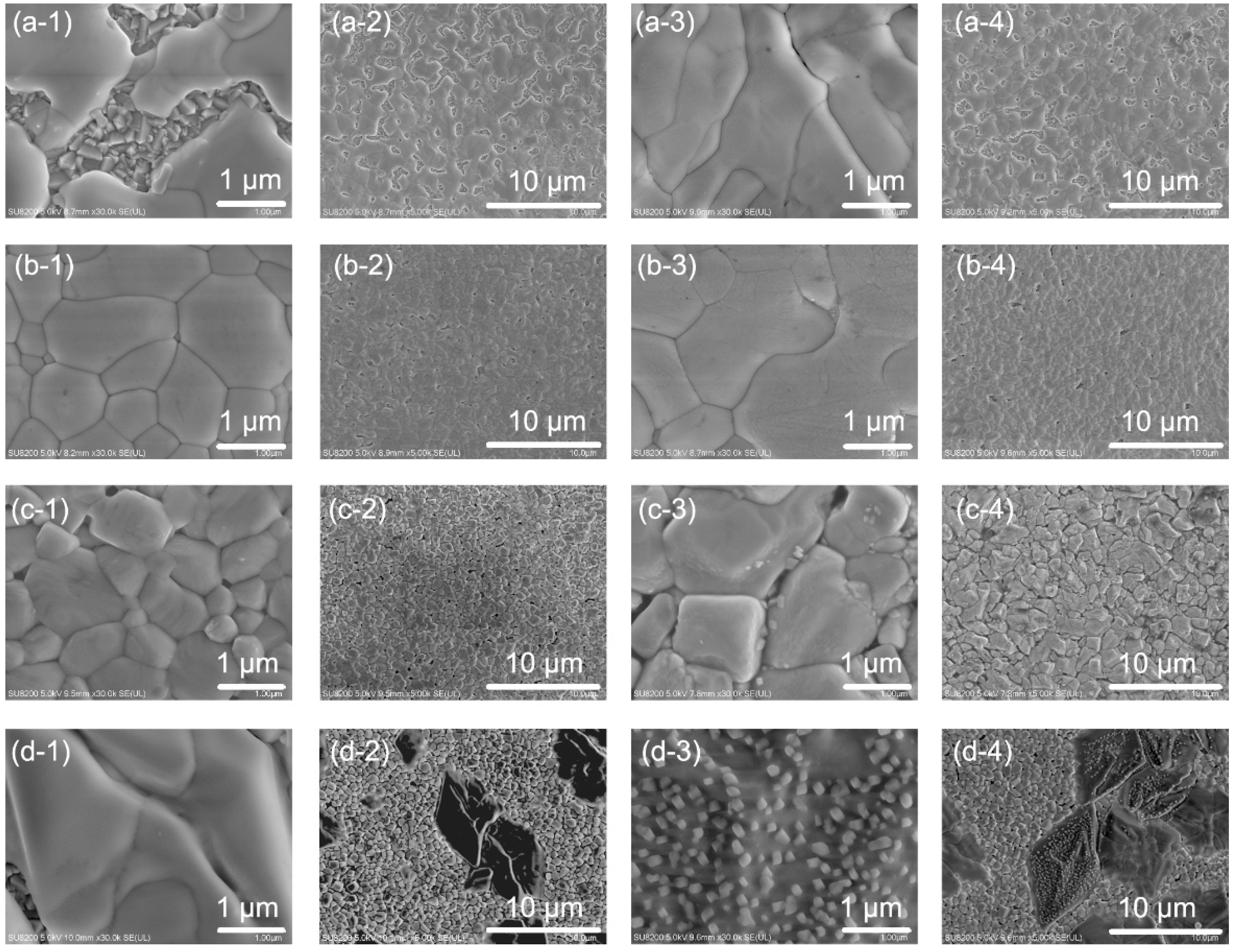
Figure 1 shows the SEM images of CsPbBr
3 film collected to help understand the effect of different CsBr concentrations and ethanol post-treatment on the film morphology. The number of spin-coating processes of the CsBr aqueous solution was only one. The CsPbBr
3 film prepared with the 100 mg/mL CsBr aqueous solution presents the maximum coverage rate and the best surface morphology, as shown in
Figure 1. The average grain size of the CsPbBr
3 crystal is 0.88 μm with 100 mg/mL CsBr/H
2O solution and 0.60 μm with 150 mg/mL CsBr/H
2O solution. The grain size of the CsPbBr
3 crystal prepared by CsBr aqueous solution with concentrations of 50 mg/mL and 200 mg/mL could not easily be calculated.
The SEM images of CsPbBr
3 films with and without ethanol post-treatment in
Figure 1b indicate that ethanol post-treatment resulted in fewer grain boundaries due to the recrystallization of the grains. Besides, as shown in
Figure 1a, the SEM images of the CsPbBr
3 film prepared with the 50 mg/mL CsBr aqueous solution show a low coverage rate and large voids, which should significantly reduce the photovoltaic performance of CsPbBr
3 devices. The SEM images of the CsPbBr
3 film prepared with 150 mg/mL solution show a few CsBr crystal particles at the grain boundaries after the ethanol post-treatment, as shown in
Figure 1(c-3,c-4), which are distinguishable from needle-like PbBr
2 crystals. It is speculated that the excess of CsBr leads to the formation of Cs
4PbBr
6, and that the excess of CsBr is separated from the Cs
4PbBr
6 crystal by ethanol post-treatment and precipitated at the grain boundary. It is proved in the following XRD patterns. The SEM images of the CsPbBr
3 film prepared with 200 mg/mL CsBr solution present huge perovskite grains with a low coverage rate. Besides, more CsBr grains appeared after ethanol post-treatment as shown in
Figure 1d. The high concentration of CsBr aqueous solution leads to the formation of CsBr-rich crystals (Cs
4PbBr
6), and the ethanol post-treatment promotes the recrystallization of CsPbBr
3 films and the precipitation of CsBr.
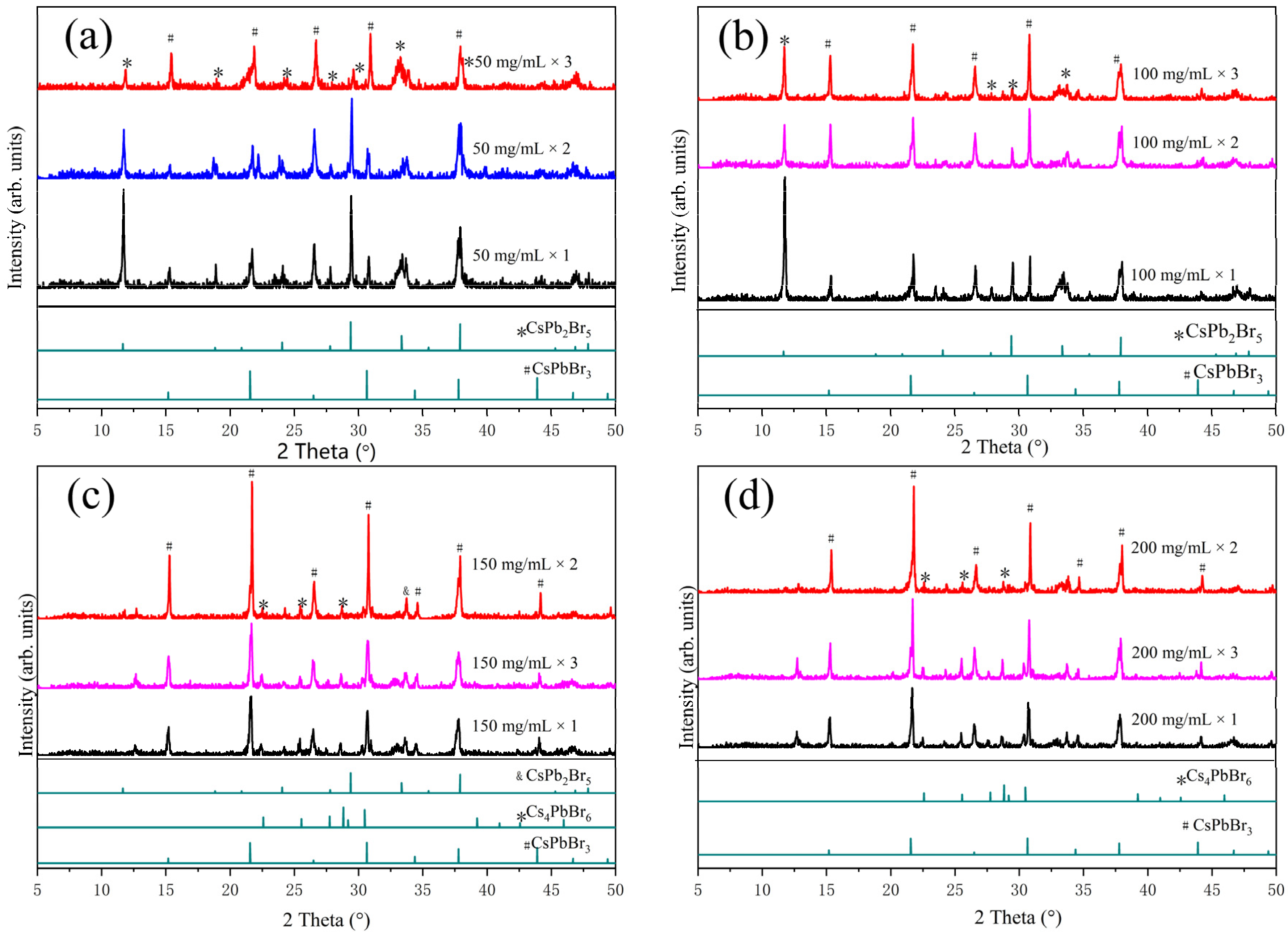
XRD was performed to study the impact of the concentration of CsBr solution, spin-coating cycles, and ethanol post-treatment on the crystal quality of CsPbBr
3 films.
Figure 2a–d show XRD results of CsPbBr
3 films prepared with different concentrations of CsBr solution and spin-coating cycles. After spin-coating once with a low concentration of CsBr solution, the CsPbBr
3 film with an excess of the CsPb
2Br
5 phase was formed, which gradually converted into the CsPbBr
3 phase when the number of spin-coating cycles was increased. High-purity CsPbBr
3 film can be prepared by spin-coating only once time when a high concentration of CsBr solution was used. As the number of spin-coating cycles of CsBr solution increased, the CsPbBr
3 film gradually transformed into the Cs
4PbBr
6 phase. This is consistent with the mechanism of the generation of the CsPbBr
3 phase.
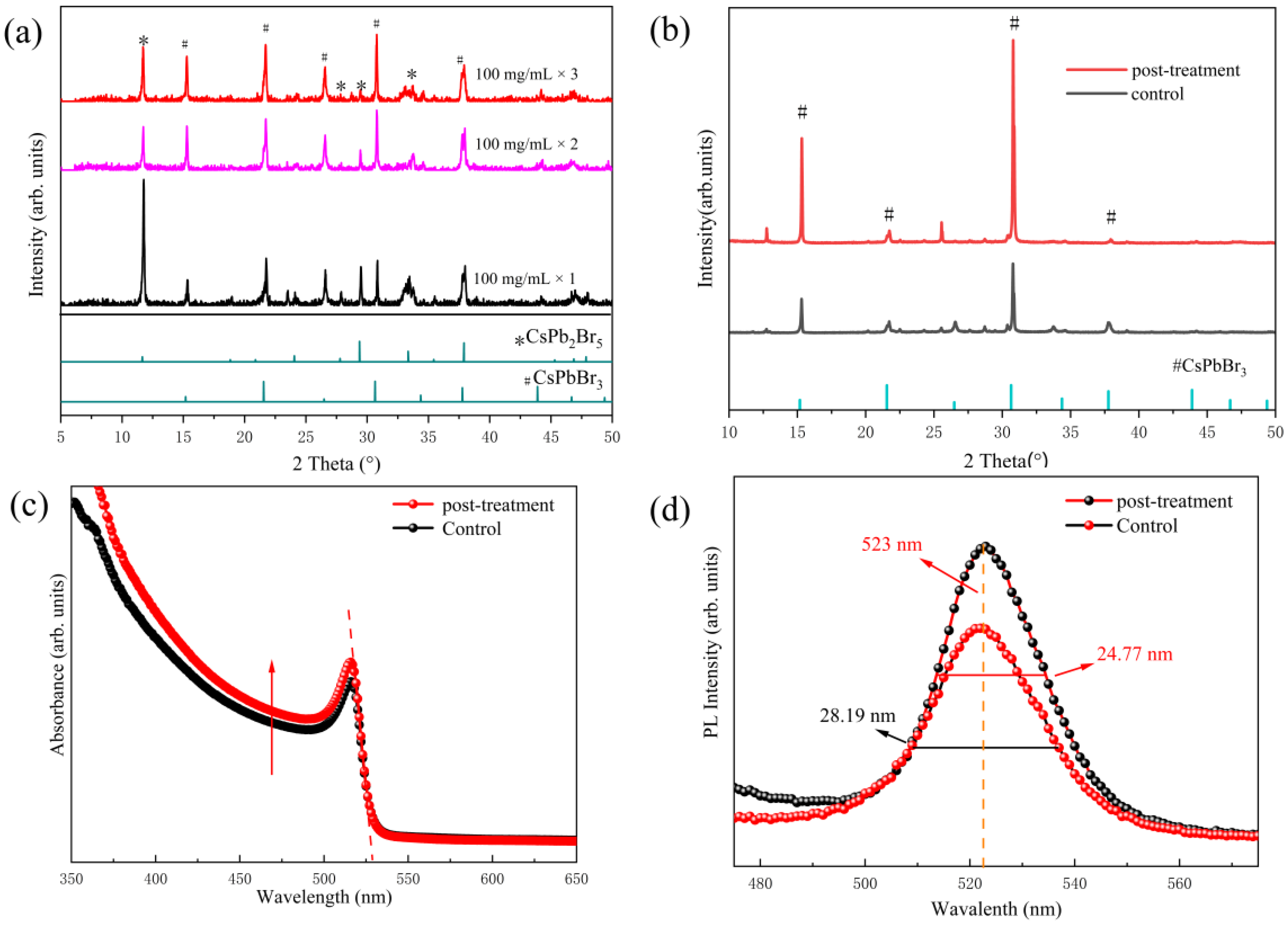
When the concentration of CsBr solution was set to 100 mg/mL, the XRD patterns of the CsPbBr
3 films prepared with a different number of spin-coating cycles of CsBr solution and ethanol post-treatment are shown in
Figure 3a,b. As shown in
Figure 3a, the CsPb
2Br
5 phase gradually changes into the CsPbBr
3 phase with an increase in the number of spin-coating cycles, indicating that the CsPbBr
3 film changes from a PbBr
2-rich phase to a CsPbBr
3 phase. Furthermore, when spin-coating 100 mg/mL CsBr solution three times, the crystal quality of the CsPbBr
3 film has been significantly improved after ethanol post-treatment, as proved by the higher peak strength and narrower half-height width, as shown in
Figure 3b.
The UV-vis absorption spectra of the CsPbBr
3 films after spin-coating 100 mg/mL CsBr solution three times were evaluated to determine the light absorption capability, as shown in
Figure 3c.
Compared to the CsPbBr
3 film without ethanol post-treatment, a slight increase in absorbance was observed after the ethanol post-treatment, which is attributed to the increased phase purity of the CsPbBr
3 film. After measuring the cut-off position of the absorption spectrum, the band gap of the two films does not change. At the same time, it can be judged that the band gap of the CsPbBr
3 film has not changed after the ethanol post-treatment from the position of dotted lines in the figure, which also proves that ethanol post-treatment does not change the composition of the CsPbBr
3 film. The position of the dotted line extending to the
x-axis is at approximately 523 nm, corresponding to an optical band gap of 2.37 eV, which is consistent with the previous literature [
26].
In addition, the steady-state photoluminescence (PL) spectra of the CsPbBr
3 films with and without ethanol post-treatment were also tested, as shown in
Figure 3d. For the steady-state PL test, the CsPbBr
3 films were directly deposited on the FTO substrate without deposition of the carrier transport layer. A higher PL strength means that there are fewer defects. The steady-state PL spectra showed that the CsPbBr
3 film with ethanol post-treatment has higher PL strength, indicating that the film has lower defect density, which is attributed to the reduced grain boundary and improved crystal quality after the ethanol post-treatment. In addition, the enhanced PL peak in the ethanol post-treated film also proves that the phase purity of CsPbBr
3 is improved, in accordance with the earlier XRD results. The positions of PL peaks remain immobile after ethanol post-treatment, implying that the composition of the CsPbBr
3 film was not changed after ethanol post-treatment.
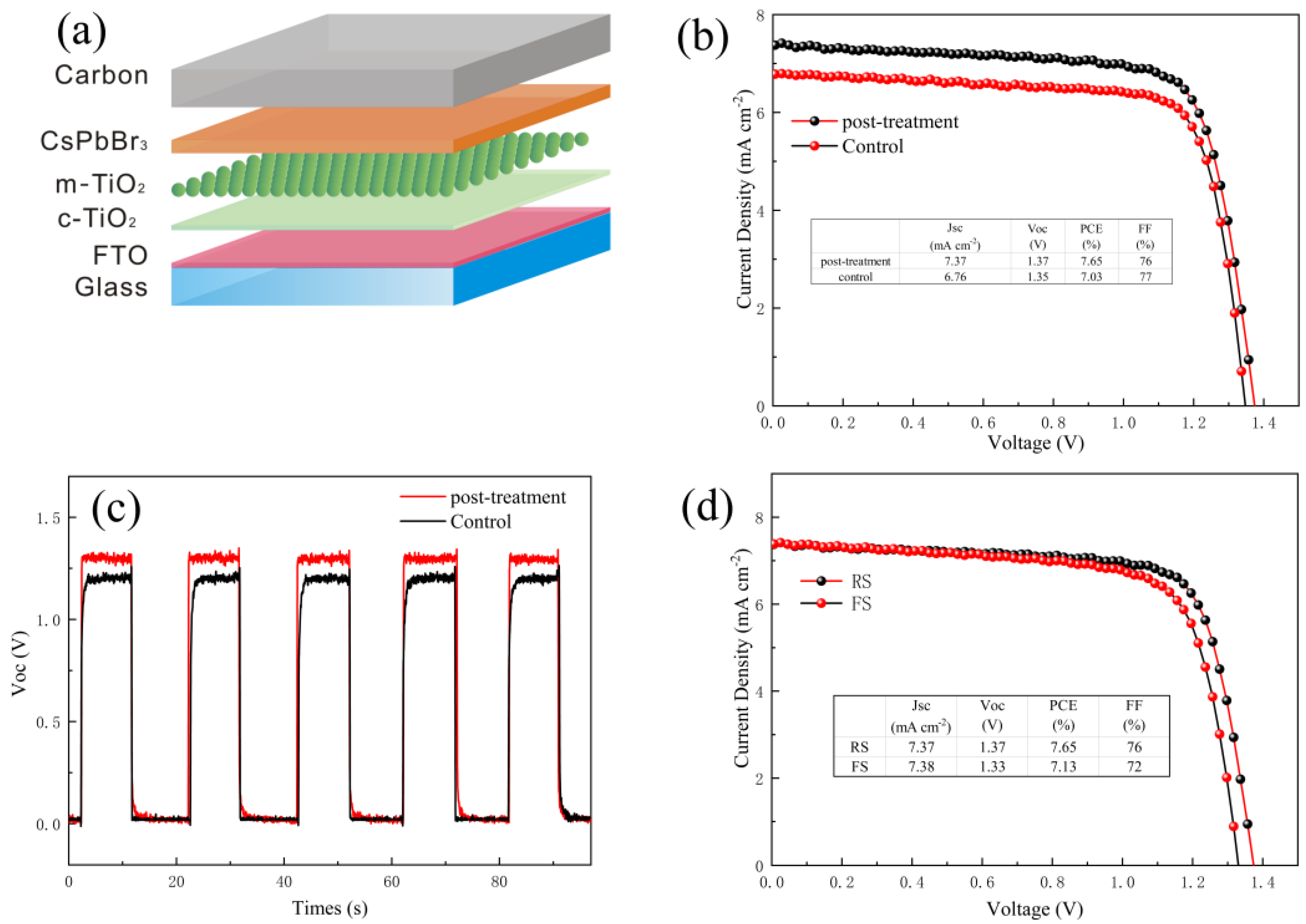
Solar cell devices with a structure of FTO/C-TiO
2/mp-TiO
2/CsPbBr
3/Carbon have been fabricated based on CsPbBr
3 perovskite film prepared by spin-coating 100 mg/mL CsBr solution three times. The voltammetric characteristics of the devices were compared without and with ethanol post-treatment. The test was carried out with a voltage range of [1.5 V, −0.5 V]. As shown in
Figure 4b, after ethanol post-treatment, the PCE of the perovskite solar cell was obviously improved. The performance improvement is mainly reflected in the
Jsc, which indicates that the ethanol post-treated film has less charge loss. This is due to the reduced grain boundary and improved crystal quality, as stated earlier.
It has been reported that the density of defect states at the surface and interface of perovskite films will lead to a slow optical response [
27] as seen in the transient
Voc measurement under light/dark cycling in
Figure 4c. Noticeably, the response of untreated devices was slower than that of ethanol post-treated devices. The first dark/light transition shows that the
Voc of the post-treated device reaches a steady-state maximum in less than 1 s, while the untreated device takes more than 3 s for the
Voc to reach steady-state. Results of the transient
Voc measurement demonstrate that the ethanol post-treatment reduces the defect density in the CsPbBr
3 film.
Figure 4d shows the results of the forward and reverse scanning J-V curves. It can be observed from the J-V curves that the hysteresis of the optimized devices with ethanol post-treatment is relatively small.
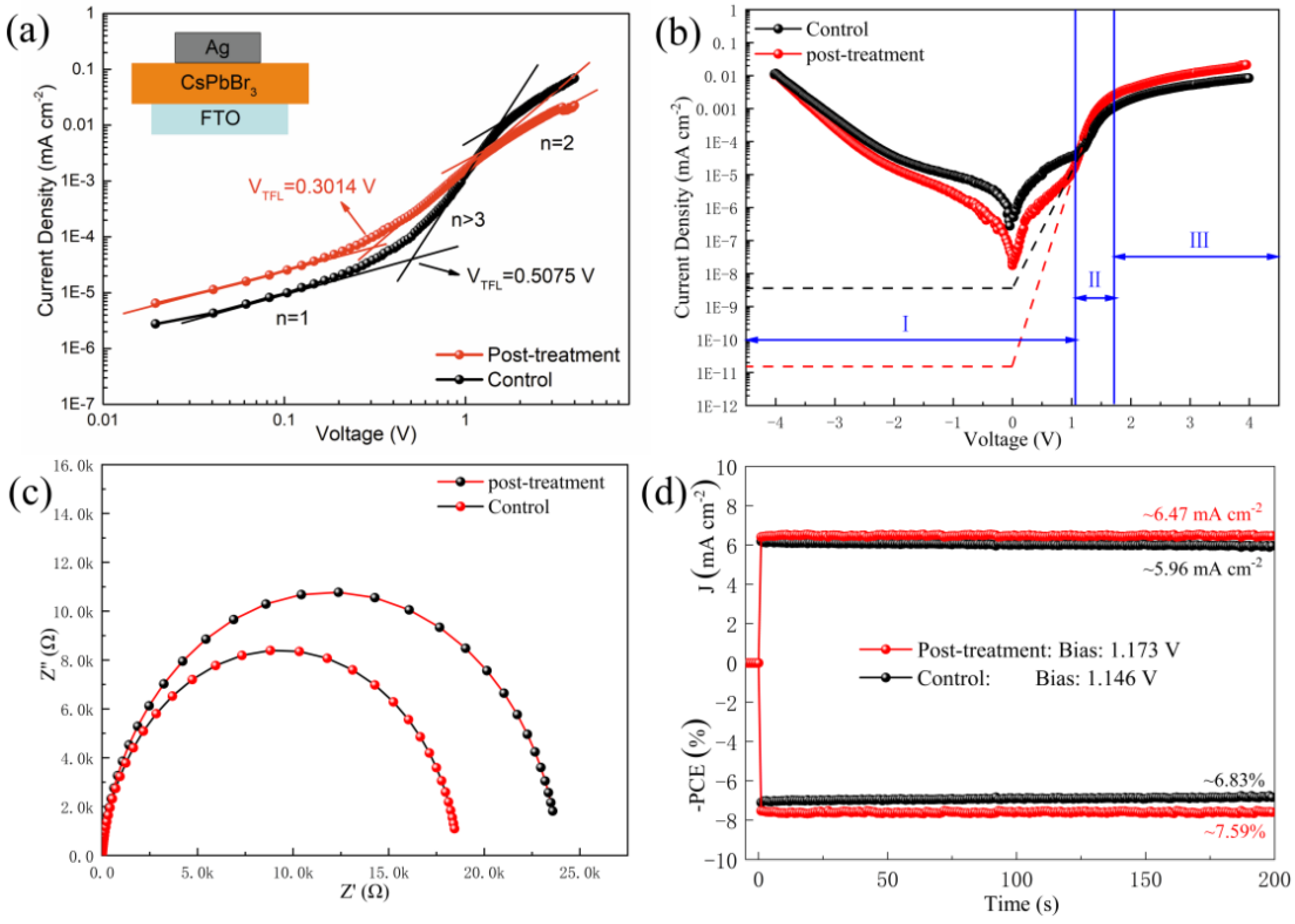
To understand the mechanism by which the ethanol post-treatment influences the performance of the CsPbBr
3 solar cell, we conducted SCLC measurements of the optimized device with an FTO/CsPbBr
3/Ag structure [
28].
Figure 5a shows the SCLC curves measured in a dark environment. The voltage of the trap filling limit (
VTFL) can be obtained from the SCLC curve, and the
Ntrap can be calculated according to below Equation (1) [
5]:
where
q is the electron charge,
ε0 and
εr are the vacuum permittivity and relative permittivity (
εr = 22), and
L is the thickness of the perovskite film (Control:
L = 431 nm post-treatment:
L = 460 nm). According to the SCLC curves in
Figure 5a, the
VTFL of untreated and ethanol post-treated CsPbBr
3 films is 0.5070 and 0.3014 V, and the calculated
Ntrap is 6.463 × 10
15 cm
−3 and 3.468 × 10
15 cm
−3, respectively. Obviously, the
Ntrap value in the ethanol post-treated CsPbBr
3 film was much lower than that in the untreated CsPbBr
3 film. It can be concluded that ethanol post-treatment can effectively reduce defects and traps in the CsPbBr
3 film.
Figure 5b shows the J-V curves in a dark environment. The dark J-V curve can be divided into three parts. The leftmost low-voltage area is the first part (I area) and the dark current density value can be read directly in this area when the voltage is 0 V. The dark current density value is used to characterize the leakage current of the device. As shown in
Figure 5b, the dark current density of the ethanol post-treated PSC was about two orders of magnitude lower than that of the untreated device, implying that the ethanol post-treated PSCs can reduce charge carrier recombination losses.
The second part (II area) is an exponential function, in which the slope is the reciprocal of the series resistance (
Rs) of the device. The lower
Rs indicates the higher the
Jsc of the device. We can see from
Figure 5b that the device exhibits an increased slope and decreased
Rs after ethanol post-treatment, indicating that the ethanol post-treatment improves the interface contact of the device. The height of the third part (III area) is related to the shunt resistance (
Rshunt) of the device. The higher shunt resistance means the lower
Voc loss of the device [
29]. The value of
Voc can be calculated by Formula (2) [
30]:
where
kB is the Boltzmann constant,
T is thermodynamic temperature,
q is the elementary charge,
Jsc is the short-circuit current, and
J0 is the longitudinal intercept of the fitting line in the second part. According to the calculation, the
Voc of the ethanol post-treated device is higher than that of the untreated device. Based on the discussion above, it can be concluded that the improvement in the photovoltaic performance of the device with ethanol post-treatment is due to the reduced defects and carrier recombination losses in the CsPbBr
3 film, as well as the enhanced interface contact of the device.
To investigate the recombination of carriers, the EIS of the devices prepared with and without ethanol post-treatment was measured under a dark environment with a 0.8 V bias voltage. The corresponding Nyquist plot is shown in
Figure 5c. Obviously, the Rs value of the control PSC is approximately equivalent to the Rs value of the ethanol post-treatment PSC owing to the identical device architecture. Based on the Nyquist plot, the R
rec increases from 18.615 kΩ (for the untreated device) to 23.908 kΩ (for the ethanol post-treated device), implying the suppressed recombination after ethanol post-treatment.
A maximum power point steady-state output test was performed on the devices prepared with and without ethanol post-treatment to evaluate the device’s reliability and stability, as illustrated in
Figure 5d. We can see that the steady-state output current density is increased from 5.96 mA cm
−2 to 6.47 mA cm
−2 after the introduction of ethanol post-treatment. Both devices show excellent stability and maintain approximately the same
Jsc for over 200 s, demonstrating the excellent stability of our CsPbBr
3 PSCs.
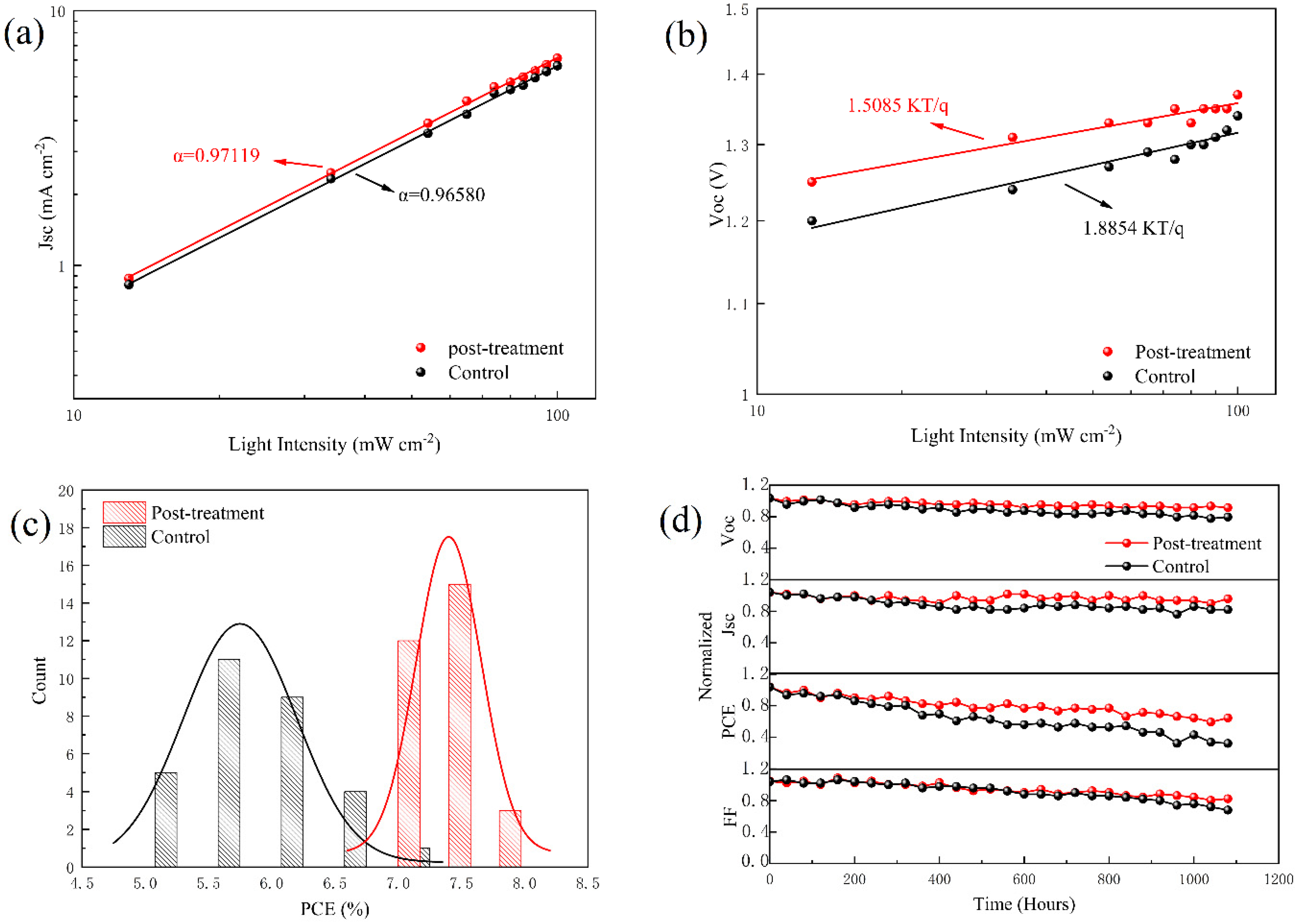
To clarify the mechanism of carrier transport and recombination in the devices prepared with and without post-treatment,
Jsc and
Voc dependence on the light intensity have been measured, and the corresponding results are shown in
Figure 6a,b, respectively. The results can be analyzed with Equation (3) [
31]:
where
is the light intensity and α is the slope. As shown in
Figure 6a,
Jsc is on the
y-axis and light intensity is on the
x-axis. Taking the logarithm of the transverse and longitudinal axes and the slope is the
α. The
α value for the device prepared with ethanol post-treatment is 0.97119, while it is 0.96580 for the untreated device. By comparison, the α value of the ethanol post-treated device is closer to 1, indicating that the device has more efficient charge separation ability and less bimolecular recombination.
In addition, photovoltage attenuation tests were performed, as shown in
Figure 6b. The
Voc dependence light intensity conforms to Equation (4) [
32]:
where
is the light intensity,
n is the ideal factor,
kB is the Boltzmann constant,
T is the thermodynamic temperature, and
q is the elementary charge. In a diode, voltage and current are exponentially related and the ideal factor
n modifies this relationship, which is the combination of all the factors that cause the device to deviate from the ideal state. In perovskite solar cell devices, the ideal factor
n is usually determined by defect recombination.
The closer the ideal factor
n gets to 2, the more defect-related recombination in the device. Conversely, the closer the ideal factor
n gets to 1, the less defect-related recombination in the device. As shown in
Figure 6b, with
Voc on the
y-axis and light intensity on the
x-axis, the logarithm of the abscissa and the n value can be calculated from the slope of the curve. The calculated
n of the device with ethanol post-treatment is 1.5085 and that of the untreated device is 1.8854, implying that the defect-related recombination is reduced dramatically by ethanol post-treatment. This is attributed to the reduced grain boundary and improved crystal quality after ethanol post-treatment, as stated earlier.
To confirm the reliability of our results, we fabricated 30 CsPbBr
3 solar cell devices for each group. As shown in
Figure 6c, the PCE of each device is presented by a bar chart and Gaussian fitting curves. It can be seen that the efficiency distribution curve of the ethanol post-treated devices is much narrower than that of the untreated devices, demonstrating the improved repeatability of the devices with ethanol post-treatment.
Finally, the long-term stability based on the devices prepared with and without post-treatment was evaluated. The devices stored in ambient air (temperature ~25 °C, relative humidity ~40%) without encapsulation, and the corresponding results, are shown in
Figure 6d. It can be seen that the device with ethanol post-treatment presents much better long-term stability than the untreated device and maintains 75% of its primary efficiency after storage in a dark atmosphere environment for 1100 h. It is attributed to the passivated defect states. Thus, the high-quality perovskite film prepared with ethanol post-treatment had reduced grain boundaries and improved crystal quality, which also improves the stability of the final device.

 ,
, 


