Article

Study on Heat Transfer Performance and Parameter Improvement of Gravity-Assisted Heat Pipe Heat Transfer Unit for Waste Heat Recovery from Mine Return Air

1
School of Mechanical Electronic and Information Engineering, China University of Mining & Technology—Beijing, Beijing 100083, China
2
Beijing Zhongkuang Celebrate Energy Saving Technology Co., Ltd., Beijing 100085, China
*
Author to whom correspondence should be addressed.
Energies 2023, 16(17), 6148; https://doi.org/10.3390/en16176148
Submission received: 3 July 2023 / Revised: 13 August 2023 / Accepted: 22 August 2023 / Published: 24 August 2023
(This article belongs to the Special Issue Advanced Analysis of Heat Transfer and Energy Conversion)

Abstract

:
One of the effective methods for energy conservation and emission reduction in coal mines is to utilize waste heat recovery technology to recover mine return air waste heat. The gravity heat pipe is widely used in mine return air waste heat recovery due to its sustainable and economic advantages, but its heat transfer is a complex process influenced by multiple parameters. A single-tube heat transfer resistance model and a heat transfer calculation model based on enthalpy difference were established for the heat exchange tubes. Four typical application cases of a low flow rate and a low number of tube rows were selected, and their heat transfer characteristics were tested onsite and analyzed. It was found that there were problems such as a low overall heat transfer efficiency, a low fresh air outlet temperature, and a risk of icing in the final tube section. The effects of the gravity heat pipe parameters on the heat transfer performance were studied, such as the tube outer diameter, tube spacing, and the finned tube outer diameter. It was found that the air-resistant force of the heat exchanger increased with the increase of the tube spacing and the finned tube outer diameter, the heat transfer resistance increased with the increase of the tube spacing and the decrease of the finned tube outer diameter, and the heat transfer coefficient first increased and then decreased with the increase of the tube outer diameter. A configuration improvement scheme with a high flow rate and a high number of tube rows is proposed here. Taking Case 2 as an example, the temperature distribution of the heat tube before and after improvement is compared and analyzed. The results show that the heat transfer performance of the heat exchange system significantly improved. Without increasing the air resistance of the heat tube, the temperature of the return air outlet after improvement was reduced to 1.1 °C, 4.1 °C lower than that before improvement, further recovering the waste heat of the mine return air. The temperature of the condensate water film was greater than 0.5 °C, avoiding the icing problem of the condensate tube section, the fresh air outlet temperature reached 5.2 °C, an increase of 7.8 °C compared to that before improvement, and the overall heat transfer efficiency increased from 56.7% to 66%.

1. Introduction

With the escalating global climate change and environmental pollution, energy conservation and emission reduction have become focal points of international concern. China faces low energy efficiency, inadequate economic benefits, and eco-environmental pressures. As an essential component of the energy development strategy, energy conservation, emission reduction, and improving the overall energy efficiency are prioritized as fundamental pathways to tackle China’s energy issues. As the main energy source and essential industry raw material, coal is pivotal in the nation’s economic development and energy security, while also contributing to carbon emissions. Therefore, clean utilization and energy conservation of coal are of paramount importance [1,2]. Waste heat recovery and utilization technology refers to the technology of recycling and reusing the waste heat generated by industrial processes. Mine return air has a high volume of waste heat, with the characteristics of low temperature, high humidity, and a large air volume. The use of waste heat recovery and utilization technology to recover waste heat from mine return air is one of the most effective ways to save energy and reduce emissions in coal mines and has important economic and social value. There are two types of waste heat utilization technologies for mine return air: one is directly recovering the waste heat of the mine return air through direct contact between the spray water and the mine return air, and the other is indirect absorption of waste heat from mine return air through inter-wall heat exchangers [3,4], heat pipe heat exchangers, or ethylene glycol solution heat exchangers [5,6]. The heat tube heat transfer technology belongs to the category of unpowered heat transfer, with low operating costs, minimal maintenance, and a strong heat transfer performance. It has been widely applied and promoted in recent years. Heat tube heat exchangers mainly include gravity-assisted heat pipes, closed-loop-type heat pipes, and pulsation-type heat pipes. Among them, closed-loop-type heat pipes and pulsation-type heat pipes are mainly used for cooling electronic components, while gravity-type heat pipes are mainly used for medium to large waste heat recovery cases.
Due to its sustainable and economic advantages, the gravity-assisted heat pipe is a key piece of equipment for recovering waste heat from mine return air. With the accumulated technological advancements, its application has exceeded 20 cases. Many scholars have conducted systematic and in-depth research through parameter optimization, thermodynamic optimization, and experimental analysis to enhance the heat transfer capacity of the gravity-assisted heat pipe [7,8,9,10,11,12]. Some scholars have used FLUENT 2019R1 software to simulate heat transfer systems with heat pipes under high-humidity conditions [13,14,15], primarily studying the heat transfer between the heat pipe heat exchanger and humid air. They have particularly focused on analyzing the heat transfer capacity of the heat pipe heat exchanger under different flow fields. Other scholars [15,16,17,18] established heat transfer models for fins and water films, analyzing the influence of condensate water on heat transfer, mainly for air conditioning cooling and dehumidification scenarios. Based on this, they further conducted numerical iteration using MATLAB R2022b software to analyze the impact of single parameters on heat and mass transfer effects. Some scholars have conducted research on practical engineering cases, examining the effects of low flow rates, heat transfer working fluids, heat pipe dimensions, and tube arrangements on the heat transfer efficiency of the heat pipes [19,20,21,22,23,24]. However, the current improvement research on heat transfer in air return systems mainly focuses on low flow rates and a low number of tube rows, and the studies primarily explore the impact of single factors on heat transfer, which has certain limitations. Further research on heat transfer improvement is needed under high flow rates and a high number of tube rows.
Based on the above literature review, the heat transfer between the return air and the gravity-assisted heat pipe is a complex and multi-parameter-influenced process. In this study, we establish a model for analyzing the thermal resistance of a single tube and focus on the impact of combined factors, including the fin outside diameter and tube spacing, under different tube inside diameters on heat transfer. Furthermore, we analyze the heat transfer of heat pipes under high flow rates and a high tube row count. By comparing our findings with an actual case, we provide theoretical guidance and improvement solutions for practical engineering applications.
Our research team has carried out a lot of research [25] in the early stage, established the heat exchange model of mine return air and the heat tube, calculated the final parameters of mine return air and fresh air as well as the water film temperature in the heat exchange process, performed experimental verification, investigated the heat exchange law under different wind speeds of 0 to 6 m/s, and reached the conclusion that the heat transfer coefficient increases with the increase of the flow rate under certain conditions. On the basis of the above research, here, we first establish a single-tube heat transfer thermal resistance analysis model. Then, through practical testing of four typical application cases of gravity heat pipes in mine return air waste heat recovery, the heat transfer characteristics of the gravity heat pipe system under specific working conditions are studied, and the existing problems are pointed out. In order to address the problem of the low utilization rate of mine return air waste heat and the insufficient fresh air outlet temperature to meet the design requirements in extreme environments, the focus here is on analyzing the effects of the finned tube outer diameter, tube row numbers, and tube spacing with the different tube inner diameters on the heat transfer coefficient, heat transfer thermal resistance, air-resistant force, and overall heat transfer efficiency. Finally, the parameter improvement problem of the heat exchange system of practical engineering Case 2 is studied, and a heat pipe heat exchanger parameter improvement layout scheme with a high flow rate and a high number of tube rows is proposed, providing theoretical guidance and improvement solutions for optimizing the heat pipe heat exchange system in practical engineering applications.

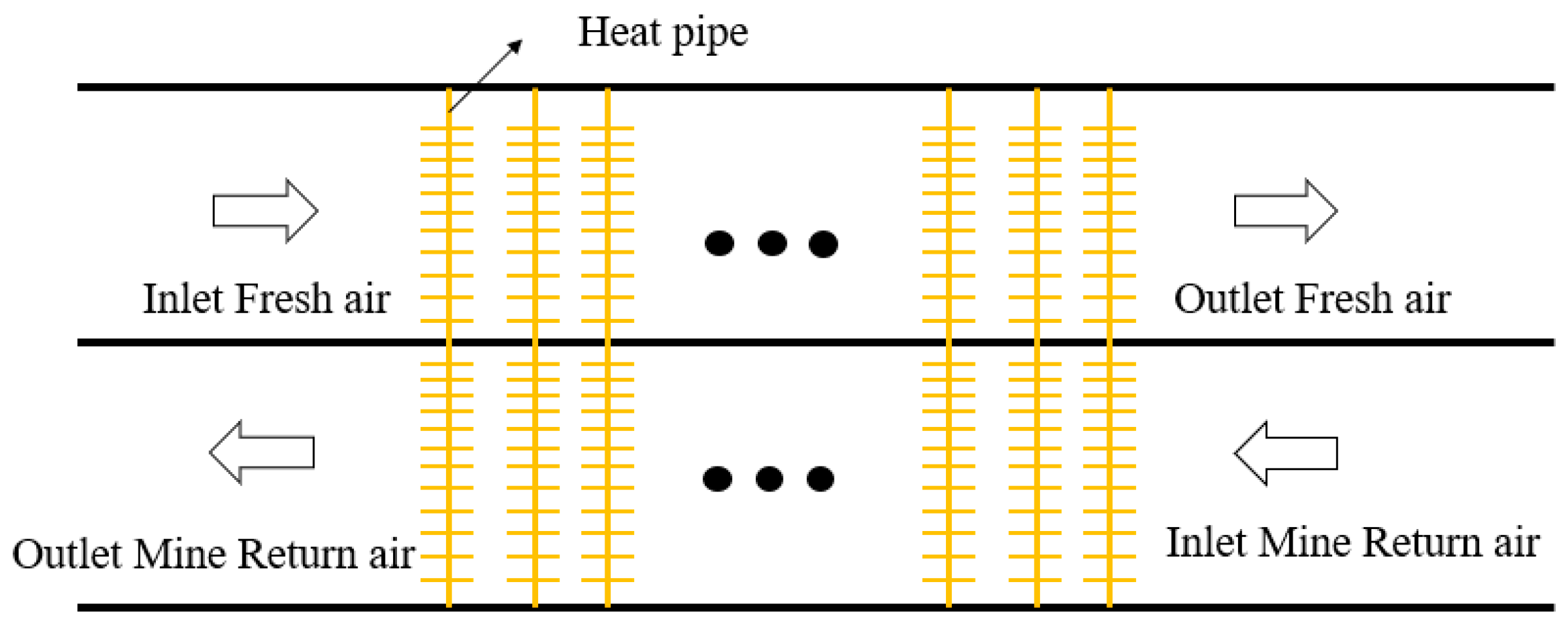
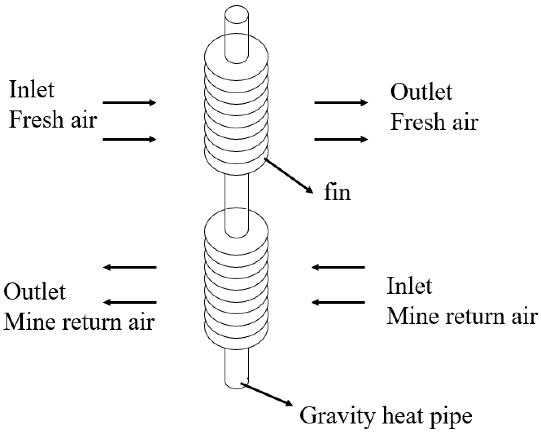
2. Principle of Gravity-Assisted Heat Pipes and the Physical Model of Heat Transfer Unit

The heat transfer unit for waste heat recovery from mine return air is shown in Figure 1. The heat transfer unit consists of two layers of air ducts, with mine return air and outdoor fresh air flowing in counterflow into the upper and lower layers of the heat transfer unit, respectively. The heat transfer unit is composed of individual heat pipes. A heat pipe is an evaporator–condenser-type heat transfer device that transfers heat through the evaporation and condensation of the working fluid inside the pipe. In the heat pipe, the evaporator section absorbs the waste heat from the return air, causing the working fluid inside to evaporate. The vapor then rises to the condenser section of the heat pipe, releasing heat to the outdoor fresh air. The internal gaseous working fluid condenses back into a liquid form and returns to the evaporator section, completing a cyclic process that facilitates heat transfer. The process of recovering waste heat from mine return air belongs to unpowered heat transfer, and the gravity-type heat pipe used is a closed chamber, unpowered equipment. The pressure inside the pipe usually does not exceed 0.6 MPa, and the working medium is R134a, which is economical and environmentally friendly. It has a long service life and low maintenance during operation. A single-tube model of the gravity-assisted heat pipe, as shown in Figure 2, was utilized for the waste heat recovery from mine return air.

3. Heat Transfer Model

3.1. Thermal Resistance Model for Heat Transfer of a Single Tube

In the waste heat recovery system using the gravity-assisted heat pipe and mine return air, the heat transfer in a single tube needs to overcome the convective thermal resistance (R1) between the humid air in the return air side and the pipe wall, the conductive thermal resistance (R2) of the evaporator-side cylindrical pipe wall, the conductive thermal resistance (R3) of the condenser-side cylindrical pipe wall, the convective thermal resistance (R4) between the fresh air side and the heat pipe wall, the fouling resistance (R5) during the heat transfer, and the thermal resistance (Rg) due to the phase change and condensation of the working fluid inside the heat pipe. According to previous studies [26], the thermal resistance (Rg) inside the pipe can be neglected. Therefore, the thermal resistance (R) of a single tube is given by Equation (1), as shown in [27]:
R = i = 1 5 R i
Subsequently, R1 and R4, defined above, can be calculated using Equation (2), as follows:
R 1 = 1 A 1 h 1
R 4 = 1 A 4 h 4
where A1 and A4 represent the heat transfer areas (m2) of the evaporator and condenser sections of the single tube, respectively, while h1 and h4 represent the convective heat transfer coefficients (W/(m2·K)) of the evaporator and condenser sections, respectively.
Since the heat pipe has a finned structure, R1 also represents the external forced convective thermal resistance of the gas cross-flowing over the finned tubes. However, in contrast to R4 on the fresh air side, the return air side deals with humid conditions, where convective heat transfer occurs concurrently with the condensation heat transfer of water vapor. The convective heat transfer coefficients h1 and h4 can be calculated using Equation (4), as shown in [27]:
h = N u λ a d 1
where λa represents the thermal conductivity of the fluid at the qualitative temperature (W/(m·K)). In this study, Nu can be calculated using the following equation [28]:
N u = 0.1887 1 + 0.1 s 1 d 1 2 R e f 0.685 P r f 1 / 3 S h f 0.304
where s1 represents the transverse spacing (m) between the fins, Ref is the Reynolds number based on the average velocity at the smallest cross-section of the bundle, Prf is the Prandtl number of the airflow outside the tube, determined at the qualitative temperature, S is the spacing (m) between the fins, and hf is the height (m) of the fins.
Both R2 and R3 denote the thermal resistance (K/W) of the cylindrical wall of the heat pipe and can be expressed using Equations (6) and (7), respectively:
R 2 = ln ( d 1 / d 0 ) 2 π λ l e
R 3 = ln ( d 1 / d 0 ) 2 π λ l c
where d0 and d1 represent the inner and outside diameters (m) of the heat pipe, respectively, λ represents the thermal conductivity of the heat pipe wall (W/(m·K)), and le and lc denote the lengths (m) of the evaporator and condenser sections of the heat pipe, respectively.
The relationship between the overall heat transfer coefficient and the thermal resistances of each part of the heat exchanger can be expressed as follows:
U 0 A 0 = 1 R = 1 R 1 + R 2 + R 3 + R 4 + R 5
where U0 represents the overall heat transfer coefficient (W/(m²·K) on the surface of the heat pipe, calculated according to thermal resistance, and A0 represents the surface area (m2) for heat transfer. R5 is the fouling resistance (K/W), typically assumed to be 0.001 K/W.

3.2. Enthalpy-Based Model for Heat Transfer Calculation

Threlkeld’s method is a common calculation approach based on the enthalpy difference for analyzing the heat transfer process in heat exchangers [29]. It provides an effective way to calculate the temperature distribution in different tube rows within the heat exchanger, which makes it possible to analyze the process of heat transfer. In this study, we employed this method to calculate the pipe wall temperature and the numerical values of various parameters in the heat exchanger. Specifically, considering the evaporator side of the heat pipe as the base tube, the relationship between the overall heat transfer coefficient, U1, based on enthalpy difference, and the thermal resistance of different components in the heat exchanger is expressed as follows [27]:
1 U 1 A 0 = R 1 b 1 + R 2 b 2 + R 3 b 3 + R 4 b 4
where b1 represents the slope of the saturated air curve at the outer wall temperature of the evaporator section, b2 represents the ratio of the enthalpy difference and the temperature difference between the inner and outer walls of the heat exchanger’s evaporator section, b3 represents the ratio of the enthalpy difference and the temperature difference between the inner and outer walls of the heat exchanger’s condenser section, and b4 represents the ratio of the enthalpy difference and the temperature difference between the outer wall of the condenser section and the fresh air temperature.
Referring to [27], the equation for the overall heat transfer coefficient, U1, based on the enthalpy difference is obtained as follows:
1 U 1 = b 1 A 0 h r ( A e , w + η f , wet A e , f ) + b 2 A 0 ln ( d 1 / d 0 ) 2 π λ l e + b 3 A 0 ln ( d 1 / d 0 ) 2 π λ l c + b 4 A 0 h a ( A c , w + η f A c , f )
where Ae,w and Ae,f represent the heat transfer areas (m2) of the base pipe and fins in the evaporator section, respectively, while Ac,w and Ac,f represent the heat transfer areas (m2) of the base pipe and fins in the condenser section, respectively. ηf,wet and ηf denote the fin efficiencies (%) under wet and dry conditions and can be calculated using the method described in [30]. The iterative equation for the saturation air enthalpy, iw,m, at the average water film temperature, Tw,m, is given as follows [31]:
i w , m = i r C p a h r η f , wet b 1 h s ( i r i a ) × 1 U 1 A 0 ( b 2 + b 3 ) ln ( d 1 / d 0 ) 2 π λ b l + b 4 h a ( A c , w + η f A c , f )
where hr, hs, and ha represent the sensible heat transfer coefficient, latent heat transfer coefficient, and overall heat transfer coefficient on the return air side, respectively, while ir and ia represent the enthalpy values of the return air and fresh air, respectively.
The calculations can be performed using Equations (12) and (13), as proposed by Bump et al. [30]:
i r = i r , in + ( i r , in i a , out ) ln ( i r , in i a , out ) ( i r , out i a , in ) ( i r , in i r , out ) ( i r , in i a , out ) ( i r , in i a , out ) ( i r , out i a , in )
i a = i a , out + ( i a , out i a , in ) ln ( i r , in i a , out ) ( i r , out i a , in ) ( i a , out i a , in ) ( i r , in i a , out ) ( i r , in i a , out ) ( i r , out i a , in )
where ia,in and ia,out represent the enthalpy values (kJ/kg, dry air) of saturated air at the inlet and outlet temperatures on the fresh air side, respectively. Similarly, ir,in and ir,out represent the enthalpy values (kJ/kg, dry air) of air at the inlet and outlet temperatures on the return air side, respectively.

3.3. Overall Heat Transfer Efficiency

The overall heat transfer coefficient, thermal resistance, and overall heat transfer efficiency (or heat recovery efficiency) are parameters used to assess the performance of a heat exchanger. The overall heat transfer efficiency represents the ratio of the actual heat transferred from the hot fluid side towards the cold fluid side to the maximum heat transfer that is theoretically achievable. The calculation equation is as follows [32]:
η = Q _ a c t u a l   /   Q _ m a x
where η denotes the overall heat transfer efficiency, Q_actual represents the actual heat transfer (kW), and Q_max represents the maximum heat transfer theoretically achievable (kW).
The Q_actual and Q_max can be calculated using Equations (15) and (16), as follows:
Q _ a c t u a l = G e × ( h a c , i n - h a c , o u t )
Q _ m a x = G e × ( h a c , i n - h a c r , o u t )
where Ge represents the volume of return air (kg/s), hac,in and hac,out represent the enthalpy values (kJ/kg) of the return air inlet and outlet, respectively, and hacr,out represents the theoretical maximum available enthalpy value (kJ/kg) of the return air outlet.

3.4. Air-Resistant Force Calculation Model

The maximum mass flow rate, Gmax, of the fluid passing through the heat pipe exchanger can be expressed as follows:
G m a x = ρ V 0 / N F A
where ρ represents the density of the fluid (kg/m3), and V0 is the volumetric flow rate through the heat pipe exchanger (m3/s). NFA represents the minimum cross-sectional area of the heat pipe bundle (m2) and can be calculated by the following equation:
N F A = [ ( s l - d 0 ) - 2 ( l - δ n ) ] × l × B
where l represents the height of the heat tube fins (m), n represents the number of fins on the heat tube, δ represents the wall thickness of the heat tube (m), and B represents the number of heat tubes per row of the heat pipe exchanger.
The friction coefficient of the heat pipe heat exchanger, ζ, can be expressed by the following equation:
ζ = 37.86 ( d 0 × G m a x μ ) 0.316 × ( s l l ) 0.927 × ( s l s 2 ) 0.515
where μ represents the fluid kinetic viscosity (m2/s), and S2 represents the longitudinal tube spacing of the heat pipe rows.
The air-resistant force, f, of the heat pipe heat exchanger can be denoted by Equation (20):
f = ζ N G max 2 2 ρ g
where N represents the number of heat tube rows, and g represents the gravitational acceleration (9.8 m/s2).

4. Engineering Testing

To ensure the normal production of mines during the winter and comply with coal mine safety regulations, it is required that the inlet fresh air temperature in the wellbore should be maintained at or above 2 °C. Considering the average value of the extreme lowest temperatures during winter and the conditions of mine return air, this study conducted research on the application of heat pipe technology in four typical cases: Yangquan and Datong in Shanxi Province, Yinchuan in Ningxia, and Ordos in Inner Mongolia, represented by Case 1~Case 4, respectively. The fin parameters of the gravity heat pipe used in these four typical application cases are consistent, but the operating conditions are different. Case 1 has the highest fresh air inlet temperature, while Cases 2 to 4 are located in cold regions, in which the fresh air inlet temperature is below −30 °C, and the relative humidity of the return air belongs to a high-humidity environment. Through testing and analyzing the actual operating effects, the heat transfer characteristics of the gravity heat pipe system for mine return air waste heat recovery under specific operating conditions were studied, and the existing problems were explored to provide a data foundation for subsequent research.

4.1. Engineering Parameter

The technical parameters of the heat transfer unit via the gravity-assisted heat pipe in the above four application cases are shown in Table 1. The extreme temperature in winter is also the fresh air inlet temperature in winter. The parameters for the fins can be found in [25].

4.2. Test Instruments

The primary instruments used for the onsite experimental testing are listed in Table 2.

4.3. Test Content and Result Analysis

To compare and analyze the heat exchange capacity of heat exchangers in the four typical cases of Case 1~Case 4, the final parameters, such as the return air outlet temperature, heat exchange capacity, fresh air outlet temperature, heat transfer resistance, and heat transfer coefficient, were calculated and analyzed in each case, as shown in Table 3. Among these figures, the parameters of return air volume, the temperature and humidity at the return air inlet and outlet, as well as the fresh air volume and temperature at the fresh air inlet and outlet, were obtained by measurement, while the others were obtained via calculations.
The test error in Table 3 was calculated as the difference between the heat absorption volume in the return air section and the heat release volume in the fresh air section, divided by the heat absorption volume in the return air section. In theory, the heat absorption in the return air section should equal the heat released in the fresh air section. However, due to the complexity of the onsite environment during testing, there were certain deviations between heat absorption and heat release. According to Table 3, the test errors for all four cases were within 10%.
The surface heat transfer coefficient represents the actual heat transfer capacity of a heat exchanger, while the overall heat transfer efficiency represents the comprehensive utilization rate of heat energy. From Table 3, it can be observed that the utilization rate of return air waste heat in the four typical cases was low, and the overall heat transfer efficiency was below 60%, indicating significant space for optimization. In Case 1, the ratio of return air volume to fresh air volume was close to 1.5:1, and the return air inlet temperature and fresh air inlet temperature were 16.2 °C and 15.3 °C, respectively. After heat exchange, the fresh air outlet temperature was 0.5 °C, the return air outlet temperature was 9.8 °C, and the overall heat transfer efficiency was only 22.28%. The fresh air outlet temperatures for Case 1 and Case 2 were only 0.5 °C and −2.6 °C, respectively, which are below 2 °C and do not meet the requirement of coal mine safety regulations for the inlet air temperature in the wellbore. Additionally, there was a risk of icing on the end-row heat pipes in Case 2.
At present, the heat pipe layout with a low flow rate and a low number of pipe rows is commonly used in engineering cases. From the above analysis, it can be seen that this layout scheme has a low overall heat transfer efficiency, and there is still a large space of optimization for recycling and utilization of the waste heat from the mine return air. The temperature of the mixed inlet air (fresh air outlet) in the wellbore was low, which cannot meet the requirements of coal mine safety regulations in extreme environments, and there was a risk of icing on the end-row heat pipe. Therefore, this study focused on analyzing how the parameters of the heat tubes, such as the number of tube rows, the finned tube outer diameter, and the tube spacing, affect the heat transfer coefficient, heat transfer resistance, air-resistant force, and overall heat transfer efficiency, to seek an optimized heat transfer solution using the heat pipe.

5. The Influence of Heat Tube Parameters on Heat Transfer Performance

It can provide a theoretical basis and reference for the design of gravity heat pipes and the improvement of the heat transfer performance of heat exchangers to study the influence of heat pipe parameters on the heat transfer performance. The main factors that affect the heat transfer and air-resistant force in the heat pipe system include the tube outer diameter, tube spacing, tube wall thickness, finned tube wall thickness, fin clearance, fin pitch, etc. This study focuses on the effect of the finned tube outer diameter, tube outer diameter, and tube spacing on the heat transfer indicators.

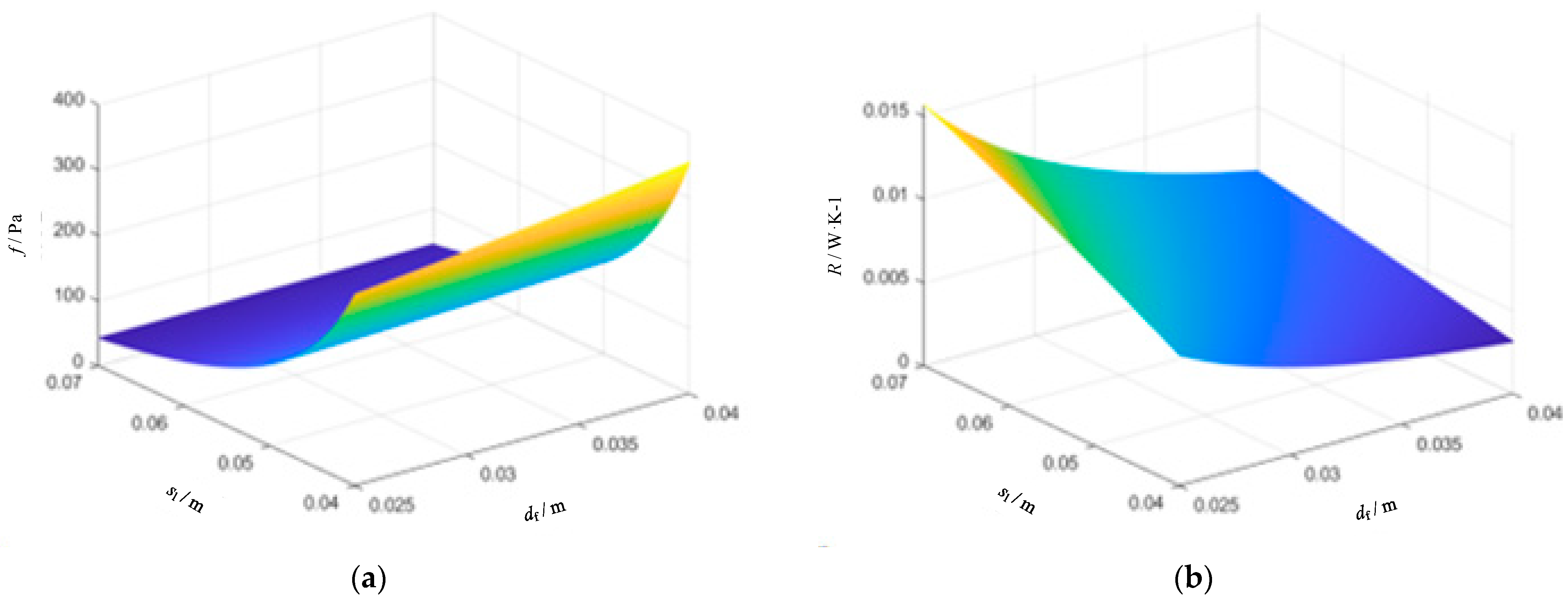
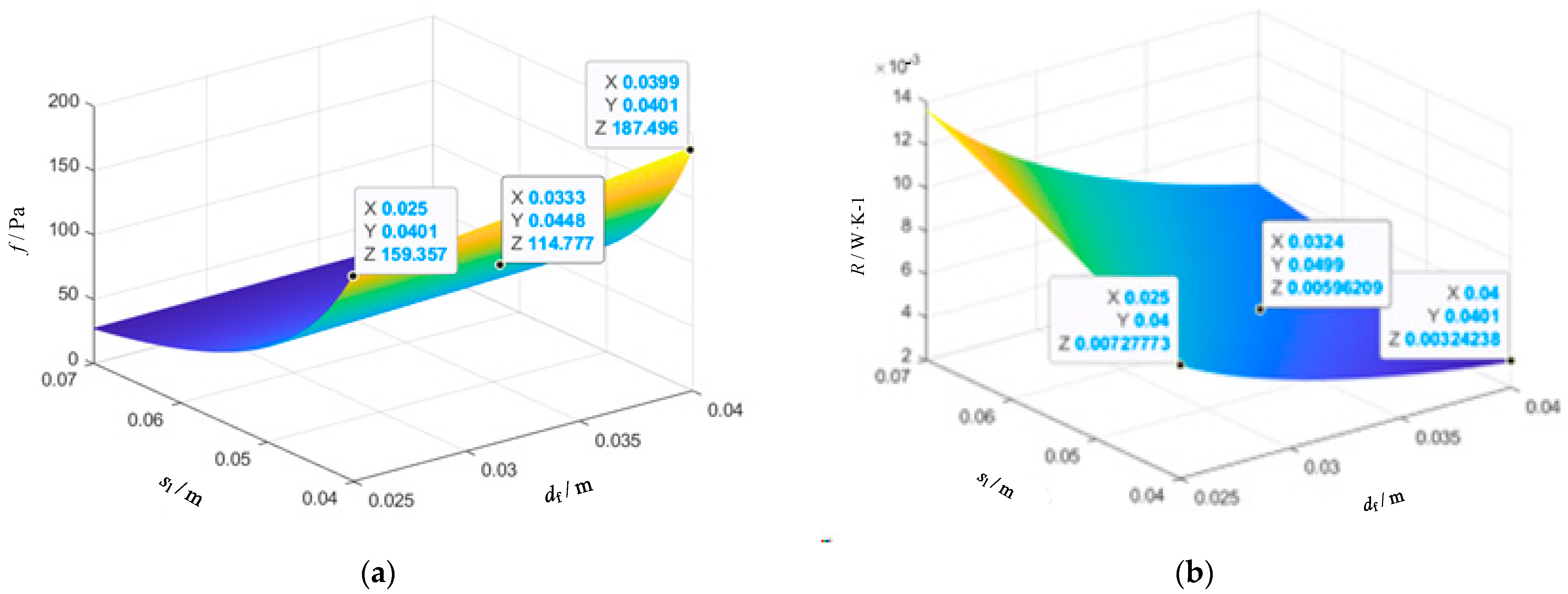
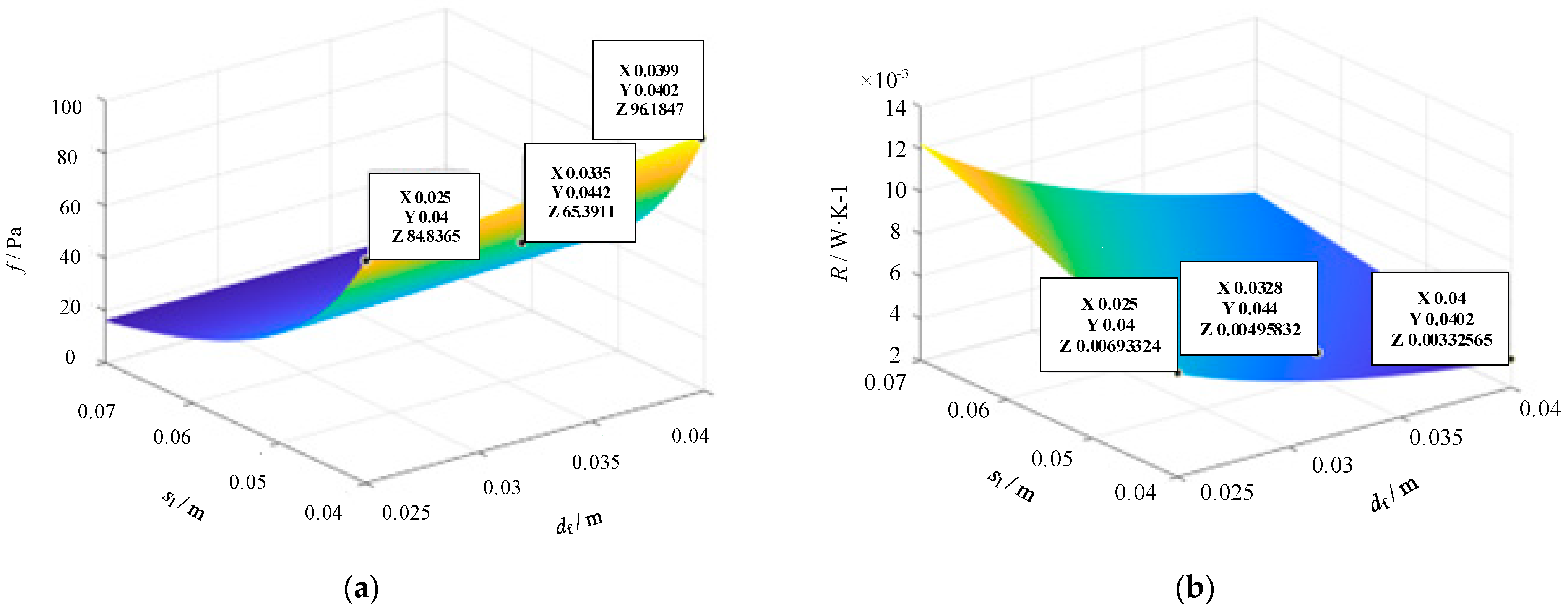
5.1. Effect of Tube Spacing and Finned Tube Outer Diameter

Considering the parameters of gravity-type heat pipes in practical engineering applications and the actual limitation that the tube spacing, sl, must be greater than the finned tube outer diameter, df, the variation ranges of the tube spacing, sl, and the finned tube outer diameter, df, are to be 0.04 m to 0.07 m and 0.025 m to 0.04 m, respectively, with a step size of 0.001 m. During calculation, the other parameters of the heat tube were as shown in Table 4. Based on the single-tube heat transfer model and the heat transfer calculation model, the effects of tube spacing, sl, and the finned tube outer diameter, df, on the air-resistant force and heat transfer thermal resistance were simulated and calculated, as shown in Figure 3. It can be seen from Figure 3a that the air-resistant force, f, increased with the decrease of the tube spacing, sl, and the increase of the finned tube outer diameter, df, and reached the maximum value of about 400 Pa when sl = 0.04 m and df = 0.04 m. As shown in Figure 3b, the heat transfer resistance increased with the increase of the tube spacing, sl, and the decrease of the finned tube outer diameter, df. From Figure 3, it can also be seen that the variation rates of the air-resistant force, f, and the heat transfer thermal resistance, R, were different with the finned tube outer diameter, df, under different tube spacings, sl, and the influence of the finned tube outer diameter on the air-resistant force, f, and the heat transfer thermal resistance, R, was also different. This is because the tube spacing, sl, directly affects the flow area of return air through the heat pipes. The smaller the tube spacing is, the smaller the flow area, the greater the flow rate, the stronger the disturbance, and the smaller the heat transfer resistance, but the greater the air-resistant force. The variation of the finned tube outer diameter, df, affects the surface heat transfer area of the heat pipe. The larger the finned tube outer diameter is, the larger the contact area between the fin and the return air, so the heat transfer coefficient will be larger and the heat recovery rate will be higher.
The primary objective of this study was to achieve a higher heat transfer capacity of the heat exchanger by minimizing the thermal resistance, R, while ensuring that the air-resistant force does not exceed 150 Pa during practical application. To accomplish this, the influence of the finned tube outer diameter, df, and tube spacing, sl, on the thermal resistance, R, and air-resistant force, f, was analyzed for heat pipes with outside diameters of 19 mm and 16 mm, respectively. The results are presented in Figure 4 and Figure 5.
Based on Figure 4 and Figure 5, it can be observed that increasing df and decreasing sl led to an increase in the air-resistant force, f. When the tube outer diameter was 19 mm, with df = 0.04 m and sl = 0.04 m, the maximum air-resistant force could reach 187 Pa. When the tube outer diameter was 16 mm, with df = 0.04 m and sl = 0.04 m, the maximum air-resistant force, f, could reach 96 Pa. From the perspective of air-resistant force analysis, the tube outer diameter directly affected the peak value of air-resistant force. Increasing df and decreasing sl resulted in a decrease in thermal resistance, R. The minimum thermal resistance occurred when df = 0.04 m and sl = 0.04 m. When the tube outer diameter decreased, the thermal resistance, R, did not rapidly decrease, but the difference was not significant. Figure 5 indicates that for heat exchangers with a 19 mm tube outer diameter, simultaneously increasing df and sl led to an increase in the air-resistant force. Below the maximum limit of resistance, there exists a reasonable combination of df and sl values, which provide a relatively optimal thermal resistance. Similarly, for heat exchangers with a 16 mm tube outer diameter, there also exists a reasonable value of df and sl.

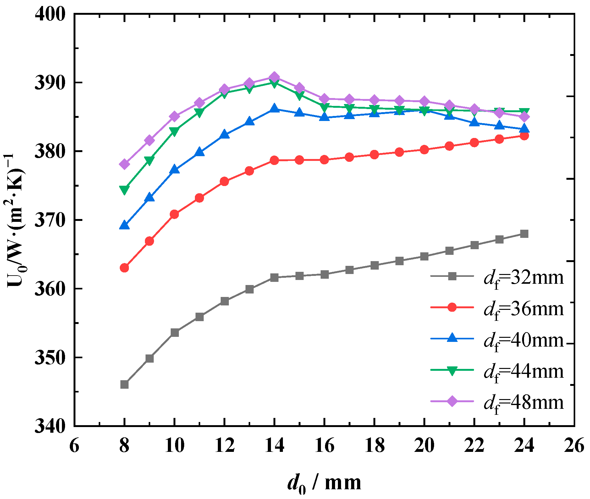
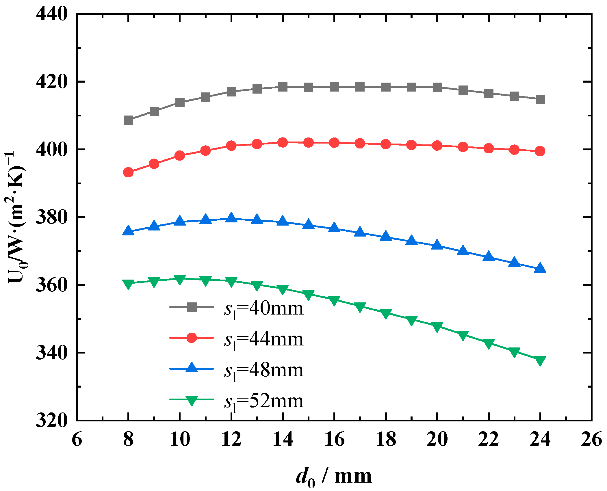
5.2. Effect of Tube Outer Diameter

Taking the engineering application of Case 4 as an example, the mine return air volume, return air inlet temperature and humidity, as well as the fresh air volume and fresh air inlet temperature were as shown in Table 3, and the fin parameters were as shown in Table 4. The influence of the tube outer diameter on the heat transfer performance was calculated for finned tube outer diameters of 32 mm, 36 mm, 40 mm, 44 mm, and 48 mm, and for tube spacings of 40 mm, 44 mm, 48 mm, and 52 mm, respectively. The results are shown in Figure 6 and Figure 7. It can be observed that with the increase of the tube outer diameter, d0, the heat transfer coefficient first increased and then decreased, and there was an optimal tube outer diameter to maximize the heat transfer coefficient. When the finned tube outer diameter, df, increased, the heat transfer coefficient also increased, but the increase rate will slow down with the increase of the finned tube outer diameter. Due to the increase of the finned tube outer diameter, the heat transfer between mine return air and the heat pipe will produce condensate water and attach to the fins, reducing the direct contact area between the return air and the fin tube, leading to a reduction of the heat transfer coefficient. The heat transfer coefficient will increase along with the decrease of the tube spacing, sl, as the decrease of the tube spacing will lead to a decrease of the effective air flow section area and an increase of the local section flow rate, resulting in an increase of the disturbance and an enhancement of the heat transfer capability.

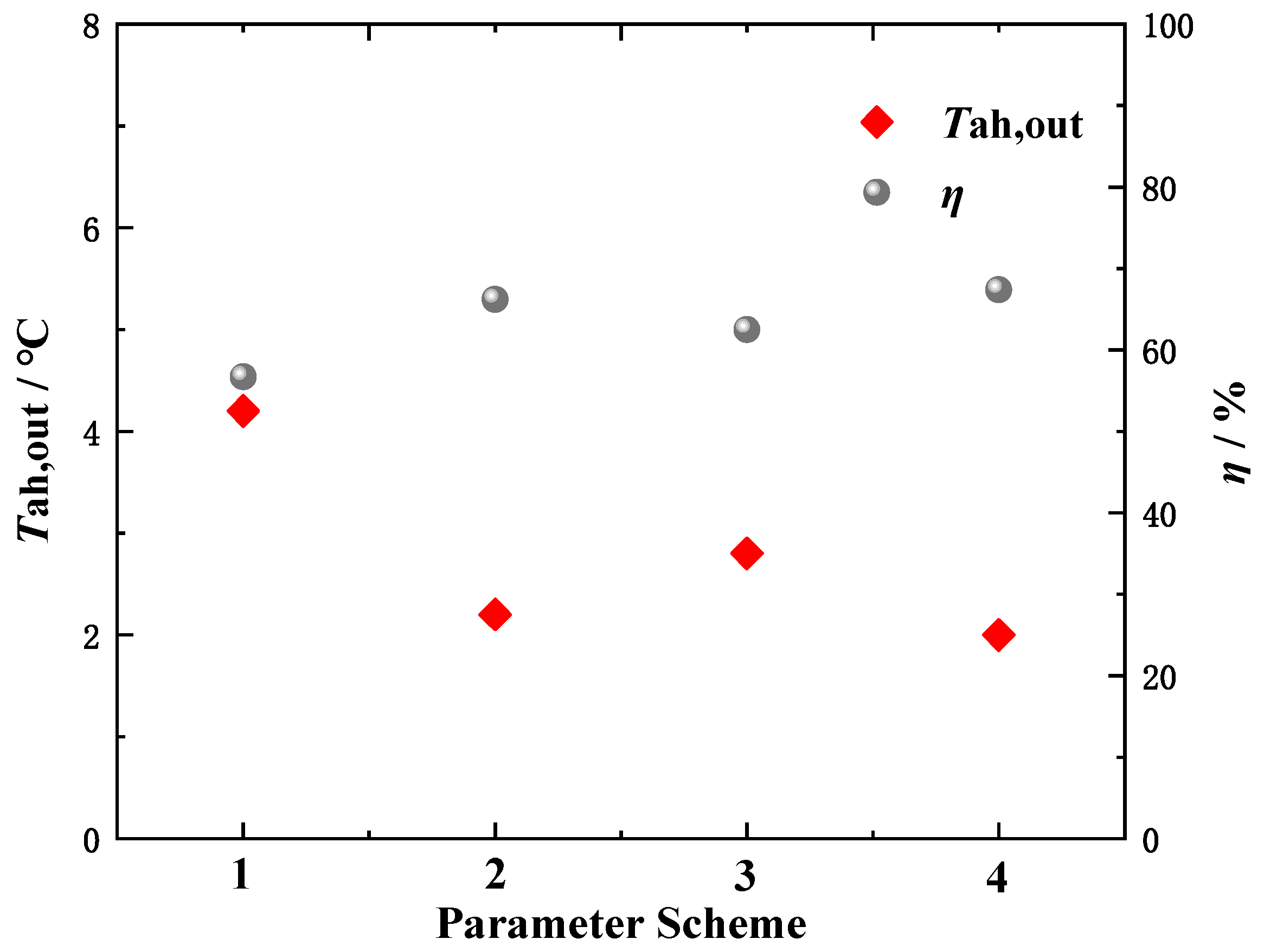
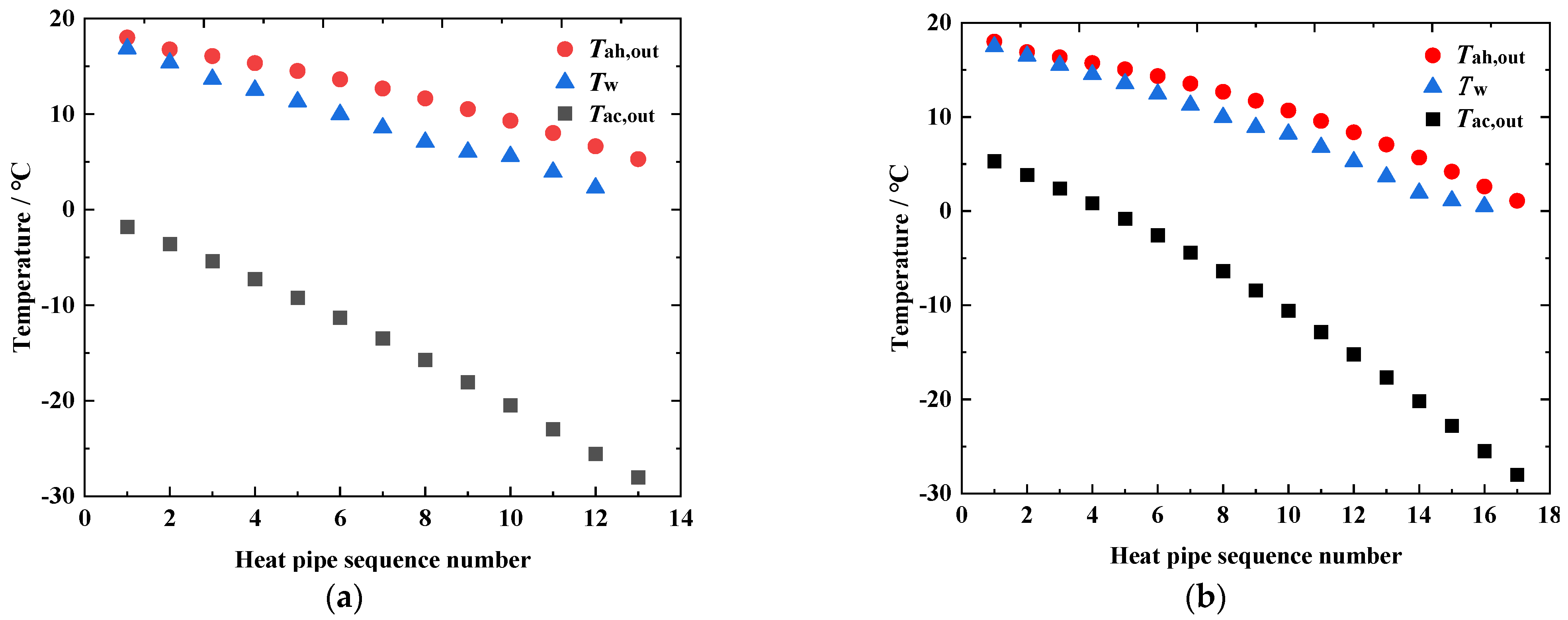
6. Parameter Improvement of the Gravity-Assisted Pipe Heat Transfer Units

To achieve a higher heat transfer capacity, it is essential to find a suitable combination value of tube spacing, sl, and the finned tube outer diameter, df, while ensuring that the air-resistant force of the heat exchanger remains below 150 Pa, according to the limit of coal mine ventilation, and that the inlet fresh air temperature in the wellbore is maintained at or above 2 °C. The improvement process is as follows:
(1) Determine the initial parameters of the heat exchanger system to be optimized, including the return air inlet temperature, return air relative humidity, fresh air inlet temperature, inlet air volume, return air volume, heat tube spacing, heat tube outer diameter, finned tube spacing, finned tube outer diameter, fin pitch, fin height, etc.
(2) Establish a thermal resistance model for the heat tube system and determine the parameter scheme to be selected.
(3) Calculate the heat tube air-resistant force, heat transfer resistance, return air outlet temperature, and overall heat transfer efficiency of the heat exchange system under different parameter combination schemes using the established heat transfer model, and determine the optimal parameter scheme of the heat tube.
(4) Calculate the distribution of the fresh air temperature, water film temperature, and return air temperature for each row of the heat tube in the improved heat pipe system using the established heat transfer model, verify whether the heat transfer performance of the improved heat pipe system meets the requirements of the coal mine safety regulations (mixed inlet air temperature in the wellbore ≥2 °C, no icing), and at the same time, ensure that the efficiency of waste heat recovery in the mine return air is higher (lower return air outlet temperature).
Therefore, this study took Case 2 as an object and determined four sets of parameter combination schemes, referring to the investigation results in Section 5, as shown in Table 5. The parameters in the first row in Table 5 are the actual parameters of the engineering application of Case 2.
Using the single-tube heat transfer model and the heat transfer calculation model, the heat transfer resistance, heat exchanger air-resistant force, return air outlet temperature, and overall heat transfer efficiency of the heat transfer exchanger with the four sets of parameter schemes in Table 5 were calculated. The results are shown in Figure 8 and Figure 9. From the two figures, it can be observed that as the outer diameter and spacing of the heat pipe decreased, the air-resistant force first decreased and then increased, the return air outlet temperature decreased, and the overall heat transfer efficiency improved. Scheme 3 had the smallest air-resistant force but a larger thermal resistance, a slightly higher return air outlet temperature, and a lower heat transfer efficiency. Scheme 4 had the lowest heat transfer thermal resistance but the largest air-resistant force, exceeding 150 Pa. The return air outlet temperature of Scheme 2 was close to that of Scheme 4, and the overall heat transfer efficiency exceeded 66%. Therefore, Scheme 2 demonstrated optimal parameters.
Referring to [25], the temperature distribution of the heat pipe rows before parameter improvement (the first group of parameters in Table 5) and after parameter improvement (the second group of parameters in Table 5) were calculated and analyzed tube-by-tube with an iterative method, as shown in Figure 10, where Tah,out represents the return air outlet temperature, Tw represents the condensate water film temperature of the heat tube wall, and Tac,out represents the fresh air outlet temperature. From Figure 10, it can be observed that for the heat exchange system with the optimized heat pipe parameters, the return air outlet temperature, Tah,out, was reduced by 4.1 °C to 1.1 °C, compared to the pre-improvement temperature, which indicates that the mine return air waste heat was further recycled and utilized. The temperature of the condensate water film on the heat pipe wall, Tw, which exceeded 0.5 °C, effectively prevented icing issues. The fresh air outlet temperature, Tac,out, reached 5.2 °C, with an increase of 7.8 °C compared to the pre-improvement temperature, which ensured that it met the coal mine safety regulations’ requirement that the mixed air temperature in the wellbore should be maintained at or above 2 °C. The presented heat exchange system significantly improved the heat transfer performance.

7. Conclusions

Gravity-assisted heat pipes are one of the key devices for recovering waste heat in the mine return air. Here, we conducted field tests and calculations on typical application cases to analyze the issues associated with the heat transfer process in gravity-assisted heat pipe units and investigate parameter improvement. The main findings were as follows:
(1)
Based on the onsite test data and calculation results, it can be seen that there is significant improvement potential for utilizing the waste heat from mine return air as there were relatively high return air outlet temperatures and a relatively low overall heat efficiency. Moreover, under extreme weather conditions, there is a risk of ice formation on the last row of tubes during actual testing.
(2)
The effect of the heat tube outer diameter, tube spacing, and the finned tube outer diameter on the air-resistant force, heat transfer thermal resistance, and the overall heat transfer coefficient of the heat transfer system was revealed.
(3)
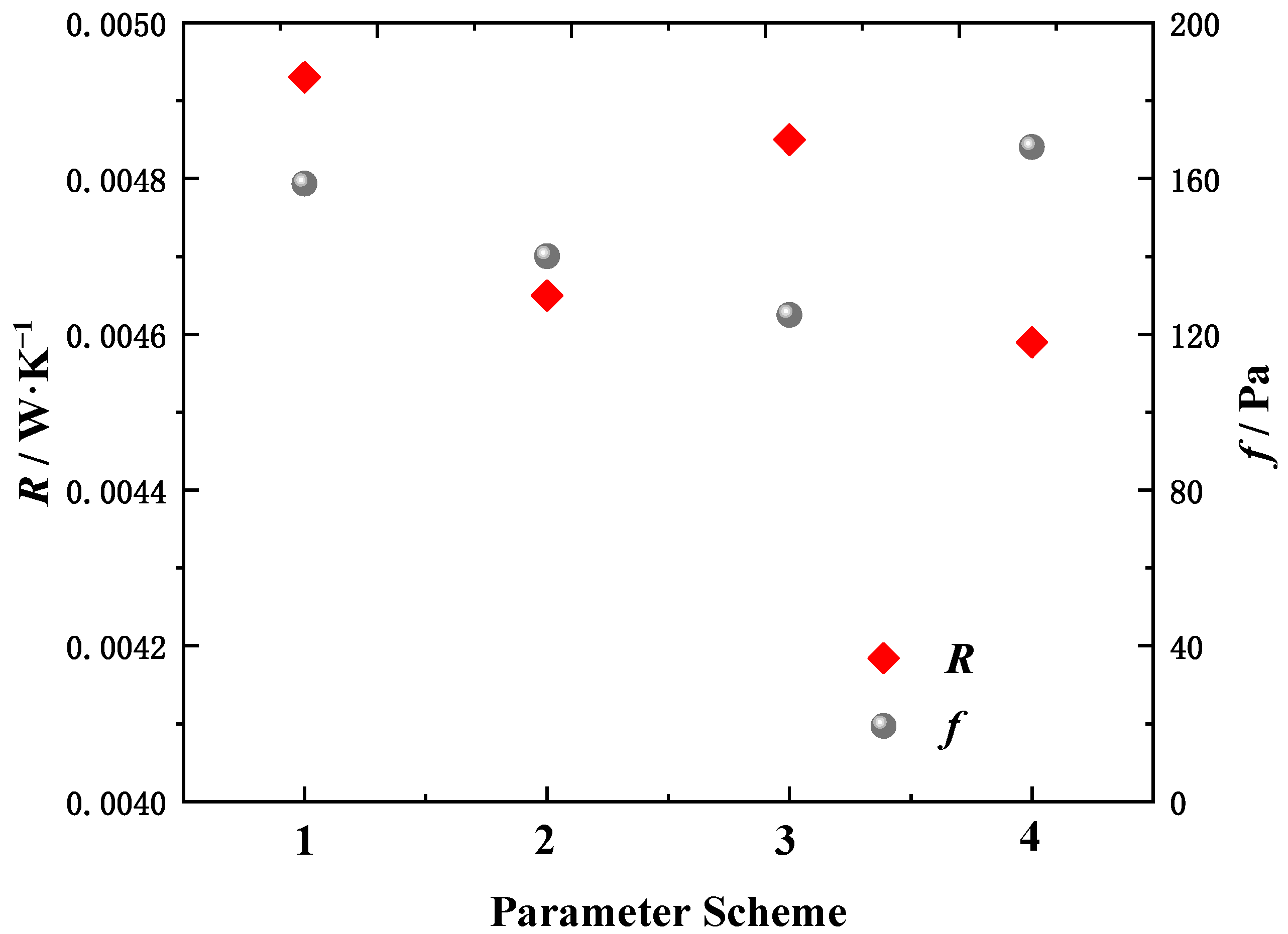
The improvement of the heat pipe parameters was studied, and a parameter layout scheme with a high flow rate and a high number of tube rows was proposed for the heat pipe exchanger.
(4)
Further research on the heat transfer performance and the establishment of mathematical models for optimizing the design of heat pipe parameters will be the focus of the next study, and the optimal scheme for the heat transfer system also needs further engineering verification.

Author Contributions

Conceptualization, Y.Z. and Z.D.; data curation, Y.Z. and X.Z.; formal analysis, Y.Z. and X.Z.; funding acquisition, Z.D.; investigation, X.Z. and Y.Z.; methodology, Y.Z. and Z.D.; projection administration, Z.D.; resources, Z.D.; software, Y.Z.; supervision, Z.D.; validation, Y.Z. and X.Z.; visualization, Y.Z.; writing—original draft, Y.Z., X.Z. and G.X.; writing—review and editing, Y.Z., G.X. and X.Z. All authors have read and agreed to the published version of the manuscript.

Funding

This research and the APC were supported by the Fundamental Research Funds for the Central Universities (Grant No. 2021YQJD31).

Data Availability Statement

Not applicable.

Acknowledgments

We appreciate that Beijing Zhongkuang Celebrate Energy-Saving Technology Co., Ltd. provided the site and the devices for the experiment during our research.

Conflicts of Interest

The authors declare no conflict of interest.

References

  1. Bai, E.; Guo, W.; Tan, Y.; Wu, D.; Zhang, Y.; Wen, P.; Ma, Z. Green coal mining and water clean utilization under Neogene aquifer in Zhaojiazhai coalmine of central China. J. Clean. Prod. 2022, 368, 133134. [Google Scholar] [CrossRef]
  2. Guo, J.; Zhang, Y.J.; Zhang, K.B. The key sectors for energy conservation and carbon emissions reduction in China: Evidence from the input-output method. J. Clean. Prod. 2018, 179, 180–190. [Google Scholar] [CrossRef]
  3. Kalantari, H.; Amiri, L.; Ghoreishi-Madiseh, S.A. Analysis of the performance of direct contact heat exchange systems for application in mine waste heat recovery. Int. J. Energy Res. 2022, 46, 290–307. [Google Scholar]
  4. Baidya, D.; de Brito, M.A.R.; Sasmito, A.P.; Ghoreishi-Madiseh, S.A. Diesel generator exhaust heat recovery fully-coupled with intake air heating for off-grid mining operations: An experimental, numerical, and analytical evaluation. Int. J. Min. Sci. Technol. 2022, 32, 155–169. [Google Scholar] [CrossRef]
  5. Zeng, C.; Liu, S.; Shukla, A. A review on the air-to-air heat and mass exchanger technologies for building applications. Renew. Sustain. Energy Rev. 2017, 75, 753–774. [Google Scholar] [CrossRef]
  6. Zhu, G.; Bao, L.; Zhao, X.; Wang, J.; Zhang, C. Design optimization of ethylene glycol interwall heat exchange wellhead antifreeze system in Yindonggou Coal Mine. Saf. Coal Mines 2022, 53, 140–145. [Google Scholar]
  7. Dobson, R.T. Theoretical and experimental modelling of an open oscillatory heat pipe including gravity. Int. J. Therm. Sci. 2004, 43, 113–119. [Google Scholar] [CrossRef]
  8. Tian, E.; He, Y.L.; Tao, W.Q. Research on a new type waste heat recovery gravity heat pipe exchanger. Appl. Energy 2017, 188, 586–594. [Google Scholar] [CrossRef]
  9. Zhang, L.Y.; Liu, Y.Y.; Guo, X.; Meng, X.Z.; Jin, L.W.; Zhang, Q.L.; Hu, W.J. Experimental investigation and economic analysis of gravity heat pipe exchanger applied in communication base station. Appl. Energy 2017, 194, 499–507. [Google Scholar] [CrossRef]
  10. Lv, X.Y.; Li, Y.N.; Bao, L.L. Research on application of recovering low temperature residual heat from mine air based on heat pipe heat transfer technology. Coal Technol. 2019, 38, 117–120. [Google Scholar]
  11. Xin, S.; Zhang, Z.P. Research on separate-type heat pipe recovery technology of mine return air waste heat. Min. Res. Dev. 2020, 40, 160–164. [Google Scholar]
  12. Adrian, Ł.; Szufa, S.; Piersa, P.; Mikołajczyk, F. Numerical Model of Heat Pipes as an Optimization Method of Heat Exchangers. Energies 2021, 14, 7647. [Google Scholar] [CrossRef]
  13. Yan, K.; Li, N.; Wu, Y.; Xie, R. Analysis of condensation flow pattern and heat transfer of a cryogenic loop heat pipe with different heating powers. J. Therm. Sci. Eng. Appl. 2022, 14, 054501. [Google Scholar] [CrossRef]
  14. Huang, W.; Chen, J.; Cen, J.; Cao, W.; Li, Z.; Li, F.; Jiang, F. Heat extraction from hot dry rock by super-long gravity heat pipe: Effect of key parameters. Energy 2022, 248, 123527. [Google Scholar] [CrossRef]
  15. Du, J.; Wu, X.; Li, R.; Cheng, R. Numerical simulation and optimization of mid-temperature heat pipe exchanger. Fluid Dyn. Mater. Process. 2019, 15, 77–87. [Google Scholar] [CrossRef]
  16. Song, C.H.; Lee, D.Y.; Ro, S.T. Cooling enhancement in an air-cooled finned heat exchanger by thin water film evaporation. Int. J. Heat Mass Transf. 2003, 46, 1241–1249. [Google Scholar] [CrossRef]
  17. Li, W.; Wu, X.Y.; Luo, Z.; Webb, R.L. Falling water film evaporation on newly-designed enhanced tube bundles. Int. J. Heat Mass Transf. 2011, 54, 2990–2997. [Google Scholar] [CrossRef]
  18. Xiao, L.; Wu, T.; Feng, S.; Du, X. Experimental study on heat transfer enhancement of wavy finned flat tubes by water spray cooling. Int. J. Heat Mass Transf. 2017, 110, 383–392. [Google Scholar] [CrossRef]
  19. Zhang, Q. Study on Heat and Mass Transfer Mechanism and Calculation Method of Evaporative Air Cooler with Finned Tubes Under Dry and Wet Conditions. Ph.D. Thesis, East China University Science Technology, Shanghai, China, 2019; pp. 50–84. [Google Scholar] [CrossRef]
  20. Zhang, Q.; Yao, D.B.; Gong, W.H. Recovery and heat exchange effect of mine return air waste heat with different heat exchangers. Coal Eng. 2021, 53, 35–39. [Google Scholar]
  21. Lu, Y.Z.; Bao, L.L.; Zhao, X.; Luo, J.H.; Wang, J.G. Heat transfer of mine heat pipe heat exchanger in dehumidifying conditions. Coal Eng. 2022, 54, 165–170. [Google Scholar]
  22. Lv, X.Y.; Zhai, Y.; Zhao, X. Application of coal mine wellhead heating based on integrated heat pipe heat exchanging. Coal Eng. 2021, 53, 57–61. [Google Scholar]
  23. Wang, K.H.; Zhao, D.X.; Luo, J.H.; Liu, H. Design and application of heat pipe self-balanced ventilation thermal energy system. Min. Saf. Environ. Prot. 2021, 48, 92–96. [Google Scholar]
  24. Hesselgreaves, J.E. Rationalisation of second law analysis of heat exchangers. Int. J. Heat Mass Transf. 2000, 43, 4189–4204. [Google Scholar] [CrossRef]
  25. Hu, W.L.; Ma, A.J.; Guan, Y.; Cui, Z.J.; Zhang, Y.B.; Wang, J. Experimental study of the air side performance of fin-and-tube heat exchanger with different fin material in dehumidifying conditions. Energies 2021, 14, 7030. [Google Scholar] [CrossRef]
  26. Zhai, Y.; Zhao, X.; Dong, Z. Research on Performance Optimization of Gravity Heat Pipe for Mine Return Air. Energies 2022, 15, 8449. [Google Scholar] [CrossRef]
  27. Kim, L.; Choi, J.H.; Jang, S.H.; Shin, M.W. Thermal analysis of LED array system with heat pipe. Thermochim. Acta 2007, 455, 21–25. [Google Scholar] [CrossRef]
  28. Teaching and Research Department of Thermal Engineering and Fluid Mechanics, Shanghai Institute of Mechanical Engineering. Heat release law of gas cross swept finned tube clusters (circular fins). Chem. Gen. Mach. 1976, 5, 10–21. [Google Scholar]
  29. Webb, R.L. Air-side heat transfer in finned tube heat exchangers. Heat Transf. Eng. 1980, 1, 33–49. [Google Scholar] [CrossRef]
  30. Pirompugd, W.; Wongwises, S.; Wang, C. A tube-by-tube reduction method for simultaneous heat and mass transfer characteristics for plain fin-and-tube heat exchangers in dehumidifying conditions. Heat Mass Transf. 2005, 41, 756–765. [Google Scholar] [CrossRef]
  31. Bump, T.R. Average Temperatures in Simple Heat Exchangers. J. Heat Transf. 1963, 85, 182. [Google Scholar] [CrossRef]
  32. Pirompugd, W.; Wang, C.C.; Wongwises, S. Finite circular fin method for heat and mass transfer characteristics for plain fin-and-tube heat exchangers under fully and partially wet surface conditions. Int. J. Heat Mass Transf. 2007, 50, 552–565. [Google Scholar] [CrossRef]
Figure 1. Illustration of the heat transfer principle in the gravity-assisted heat pipe for waste heat recovery from mine return air.
Energies 16 06148 g001
Figure 2. Single-tube model of gravity-assisted heat pipe for waste heat recovery from mine return air.
Energies 16 06148 g002
Figure 3. The effect of the tube spacing, sl, and the finned tube outer diameter, df, on the air-resistant force, f, and thermal resistance, R: (a) effect on air-resistant force, f, and (b) effect on thermal resistance, R.
Energies 16 06148 g003
Figure 4. The effect of the tube spacing, sl, and finned tube outer diameter, df, on the air-resistant force, f, and thermal resistance, R, when the tube outer diameter was 19 mm. (a) Effect on air-resistant force, f, and (b) effect on thermal resistance, R.
Energies 16 06148 g004
Figure 5. The effect of the tube spacing, sl, and finned tube outer diameter, df, on the air-resistant force, f, and thermal resistance, R, when the tube outer diameter was 16 mm. (a) Effect on air-resistant force, f, and (b) effect on thermal resistance, R.
Energies 16 06148 g005
Figure 6. Effect of the tube outer diameter, d0, on the overall heat transfer coefficient, U0, of the heat pipe surface under different finned tube outer diameters, df.
Energies 16 06148 g006
Figure 7. Effect of the tube outer diameter, d0, on the overall heat transfer coefficient, U0, of the heat pipe surface under different tube spacings, sl.
Energies 16 06148 g007
Figure 8. Calculation results of thermal resistance, R, and air-resistant force, f, for the heat exchanger with the four parameters in Table 5.
Energies 16 06148 g008
Figure 9. Calculation results of the outlet temperature of the return air, Tah,out, and the overall heat transfer efficiency, η, for the heat exchanger with the four parameters in Table 5.
Energies 16 06148 g009
Figure 10. Temperature distribution of the heat pipe before and after improvement. (a) Before improvement and (b) after improvement.
Energies 16 06148 g010
Table 1. Technical parameters of the heat transfer unit via the gravity-assisted heat pipe.
Application CaseCase 1Case 2Case 3Case 4
Extreme temperature in winter/°C−15.3−32.6−31.5−33.1
Return air temperature/°C16.215.218.316.5
Relative humidity of return air/%65859085
Return air volume/m3·min−110309246751000
Inlet air volume/m3·min−1694865539500
Cross-sectional area of return air/m21.75 × 22 × 21.75 × 21.5 × 2
Cross-sectional area of inlet air/m21.75 × 22 × 2.51.75 × 21.5 × 2
Table 2. Main instruments used in onsite experimental testing.
Instrument NameModelMeasurement RangeMeasurement UncertaintyTesting Function
ThermocoupleType T−200~+200 °C±0.1 °CFresh air temperature measurement
Multi-channel Temperature TesterTR230X−40~70 °C±0.1 °CUsed in conjunction with thermocouples
HOBO Temperature and Humidity TesterU12-013−20~70 °C
5~95% RH
Temperature: ±0.1 °C
Humidity: ±2%
Temperature and humidity of mine return air measurement
Intelligent Wind Speed and Air Volume MeterHT-6280~10 m/s±0.1 m/sWind speed measurement
Table 3. Comparison of the heat transfer capacity in four cases of heat exchangers.
Test ConditionCase 1Case 2Case 3Case 4
Return air volume Gh/kg·s−118.8816.9412.3818.33
Return air inlet temperature Tah,in/°C16.215.218.316.5
Relative humidity at return air inlet RHah,in/%65859085
Fresh air volume Gc/kg·s−112.7215.869.889.17
Fresh air inlet temperature Tac,in/°C−15.3−28.6−31.5−28.1
Return air outlet temperature Tah,out/°C9.84.25.19.4
Relative humidity at return air outlet RHah,in/%82909290
Fresh air outlet temperature Tac,out/°C0.5−2.62.82.9
Heat absorption in return air section/kW202.99430.95339.28333.05
Heat absorption in fresh air section/kW185.78416.48366.94350.1
Test error/%8.473.368.155.12
Overall heat transfer efficiency/%22.2856.755.3541.45
Thermal resistance/K·W−18.16 × 10−34.93 × 10−35.66 × 10−36.44 × 10−3
Total surface heat transfer coefficient of the heat pipe U0/W·m2 k−1354.6442.71432.93390.35
Table 4. Finned tube parameters.
ParametersFin Wall Thickness,
Δ, mm
Fin Pitch,
dY, mm
Tube Outer Diameter,
d0, mm
Tube Wall Thickness,
C, mm
Condensing section0.54221
Evaporation section0.54221
Table 5. Selected heat pipe parameters for improvement.
Parameter Scheme No.Tube Spacing,
sl, mm
Finned Tube Outer Diameter,
df, mm
Tube Outer Diameter,
mm
Number of Tube Rows
150462212
240381616
340381912
435331616
Disclaimer/Publisher’s Note: The statements, opinions and data contained in all publications are solely those of the individual author(s) and contributor(s) and not of MDPI and/or the editor(s). MDPI and/or the editor(s) disclaim responsibility for any injury to people or property resulting from any ideas, methods, instructions or products referred to in the content.

