1. Introduction
Devices that operate at elevated temperatures and under high pressures are designed in compliance with applicable standards [
1,
2]. Various parts of the boiler, such as membrane walls consisting of evaporator tubes and fins that connect them, can serve as an example. Pressure parts are subject to strict rules which are introduced as regulations or directives [
3]. In contrast, fins and other non-pressure elements are not scrutinized by supervisory authorities to the same extent. The presented work concerns a thermal-strength analysis for a fragment of the membrane wall of a steam boiler and the investigation of the cause of its damage. Therefore, the first part mainly focuses on the literature review, which indicates that such damages occur due to inadequate design. The second part presents the actual analyses and the obtained results. In conclusion, the insights that can be utilized in the design of power boilers are formulated.
As complex as the boiler structure is, it is often designed using simplified boundary conditions, with a focus only on selected pressure elements, which involves the need to look for more detailed calculation methods than those contained in relevant design standards [
4]. The studies on damage to boiler elements mainly concentrate on the analysis of pressure components, such as tubes [
5], which are prone to premature failure due to material defects and the poor state of water leading to corrosion, and thus result in the reduced thickness of the wall and ultimate bursting of the tube [
6,
7]. The effect of temperature alone is most often considered in relation to the assessment of the allowable service life for membrane wall tubes, drums or headers, taking into account phenomena such as material overheating [
6] or creep [
4,
7,
8]. Most of the works presented in the literature consist in investigations and analyses of damaged pipes, headers or drums, i.e., pressure parts [
6,
7,
9,
10,
11]. However, damage resulting in leaks in the boiler also affects non-pressure elements of the facility, such as membrane wall fins [
12,
13]. It can be caused by overheating of the material resulting in changes in the material structure, such as graphitization [
14], exceeding the limit temperature for the material creep [
15], and fatigue-related damage which is analysed in the aspect of both low- and high-cycle loads [
16].
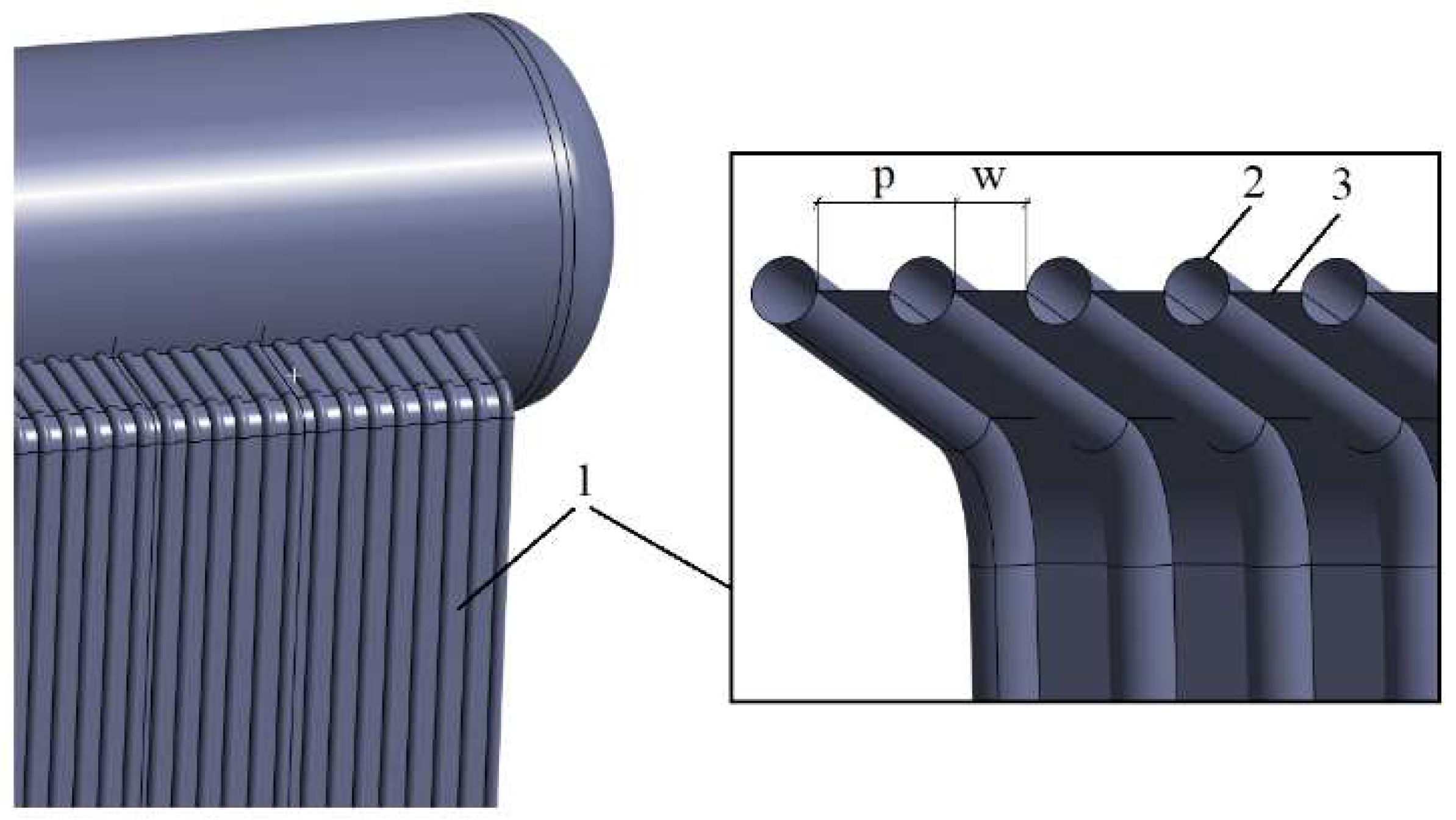
In the analysis of boiler pressure parts, such as membrane walls (
Figure 1), the main focus is on strength calculations taking account of high pressure, while elevated operating temperature is taken into consideration at lowered strength characteristics of the material [
1,
2]. Unfortunately, the thermal stresses arising due to a non-uniform temperature distribution in tubes and fins are frequently not the subject of the analysis [
17]. In most cases, thermal loads are analysed in the context of introducing correct compensation for elongations in the system of pipelines, headers and superheater tube banks [
18]. This is mainly due to the standard provisions for the boiler pressure parts, but it is often forgotten that elements such as membrane wall fins play as important a role as tubes. Their failure results in leaks, and consequently in the shutdown of the boiler. Neither the EN 12952-3 [
2] nor the EN 13445-3 standard [
19] relates directly to the method of the analysis of non-pressure elements.
For boiler elements such as membrane walls, it is particularly important to provide adequate cooling of the fins that are exposed to the impact of hot flue gases. The change in the dimensions of the fins due to thermal expansion must be analysed carefully so that it should not be greater compared to the cooled pressure parts such as the tubes connected to them. The choice of the width is essential (
w in
Figure 1) to reducing the temperature. This dimension also has an effect on the pitch of tight walls and the location of holes in headers and drums. The temperature distribution in the membrane wall of a 600 MW boiler was determined in [
20].
Non-uniform temperature distributions can cause stresses that consequently contribute to plasticization of the fins and, with time, to their failure due to variable thermal loads. However, it is not only the fins that are exposed to an increased concentration of stresses. The tubes, especially at points where the fins are welded to them, are also affected.
In the case of fatigue analyses, design standards [
1,
2,
19] are mostly based on strength analyses, with the assumption that stresses are in the range below the yield point.
The purpose of this work is to present a thermal and strength analysis for a fragment of the membrane wall of a steam boiler with a steam output of 65t/h and steam parameters of 5 MPa and 454 °C. The boiler was designed and manufactured in compliance with international standards [
1,
2,
3] and approved by the pressure equipment supervisory authority. Despite adhering to these standards, the boiler membrane wall became cyclically damaged. The results of the conducted analyses help to explain the cause of such periodic damage to the boiler. As indicated by the literature survey, only a small number of the works concern analyses of the impact of the fin thickness or width on the temperature distribution, and thus on the distribution of stresses. The paper also demonstrates the benefits of using the finite element method (FEM) as a complement to calculations performed according to design standards.
2. Thermal and Strength Analysis of a Section of a Boiler Membrane Wall
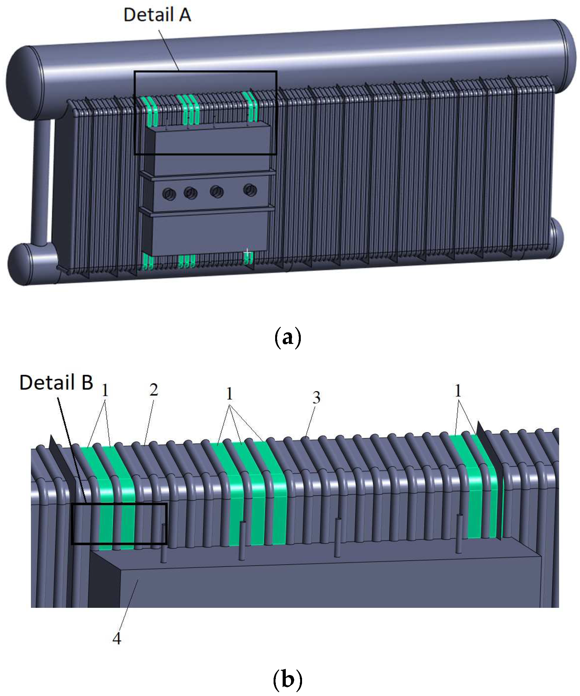
The numerical analysis of a unit as large as a power boiler requires the model to include all the elements that interact with each other. This approach is mainly necessitated by the fact that the results of the analysis also depend on the adopted boundary conditions. The analysed element of the boiler is shown in
Figure 2. The facility under consideration is a steam boiler with a steam output of 65t/h and steam parameters of 5 MPa and 454 °C. It has been in service since 2005. The boiler was designed in compliance with international standards [
1,
2,
3] and was approved by the pressure equipment supervisory authority. Nevertheless damage occurs cyclically to the boiler membrane wall (
Figure 2). A box playing the role of a closure for the system of superheaters is fixed to the analysed wall, which is a typical design solution for this kind of boiler. The box is not a pressure element, and is additionally insulated from the membrane wall using wool. This means that the box will also be an element that affects not only the temperature distribution, but also the stresses arising in the fins.
For the case under consideration, due to design requirements, some of the fins are made with larger widths compared to typical design solutions for this kind of boiler. The larger dimensions of the fins are dictated by the need to gain more space between the evaporator tubes, so that the superheater tube banks can fit between them. The tubes pass through the membrane wall between the evaporator tubes and connect to the collection chamber located in the box (
Figure 3). Detail B was analysed, as shown in
Figure 2. The choice of this location results from the load conditions to which this part of the boiler is subjected. This is the place where the superheater is installed, and where the flue gases are cooled down quite significantly over a short distance. The temperature in this region can vary from 982 °C to 678 °C. In addition, it is also the place with the greatest variation in the width of the fins due to the need to pass bundles of superheater tubes through the membrane wall. This place is also important in terms of the method of heating the membrane wall, because both convection and radiation take place here. These factors prompt a detailed analysis of this area of the boiler to understand its behavior during its operation. The width of the fins is normally no higher than
w = 50 mm, and for a few of the fins shown in
Figure 2, the width is
w = 76 mm. Fins this wide can generate higher temperatures compared to tubes and, consequently, higher gradients of temperatures and stresses. The pressure of steam in the tubes totals 50 bar, and the pressure of flue gases is 0.014 bar, which means that the latter has hardly any effect on the stresses arising in the membrane wall.
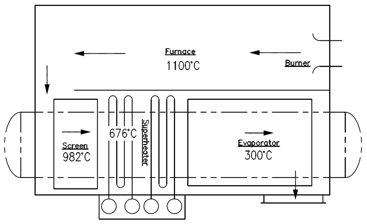
The temperatures adopted in the analyses were measured in the facility, and in the part under consideration, they are 371.1 °C and 676 °C for steam and flue gases, respectively. A schematic diagram of the boiler with the adopted temperatures is shown in
Figure 3. The boiler is fully insulated on the outside, with the box insulated inside using heat-resistant wool.
Based on the results of a site inspection, it was assumed that the temperature of the evaporator tubes could be taken as constant at 371.1 °C, and the heat transfer coefficient on the flue gas side was estimated at 40 W/m
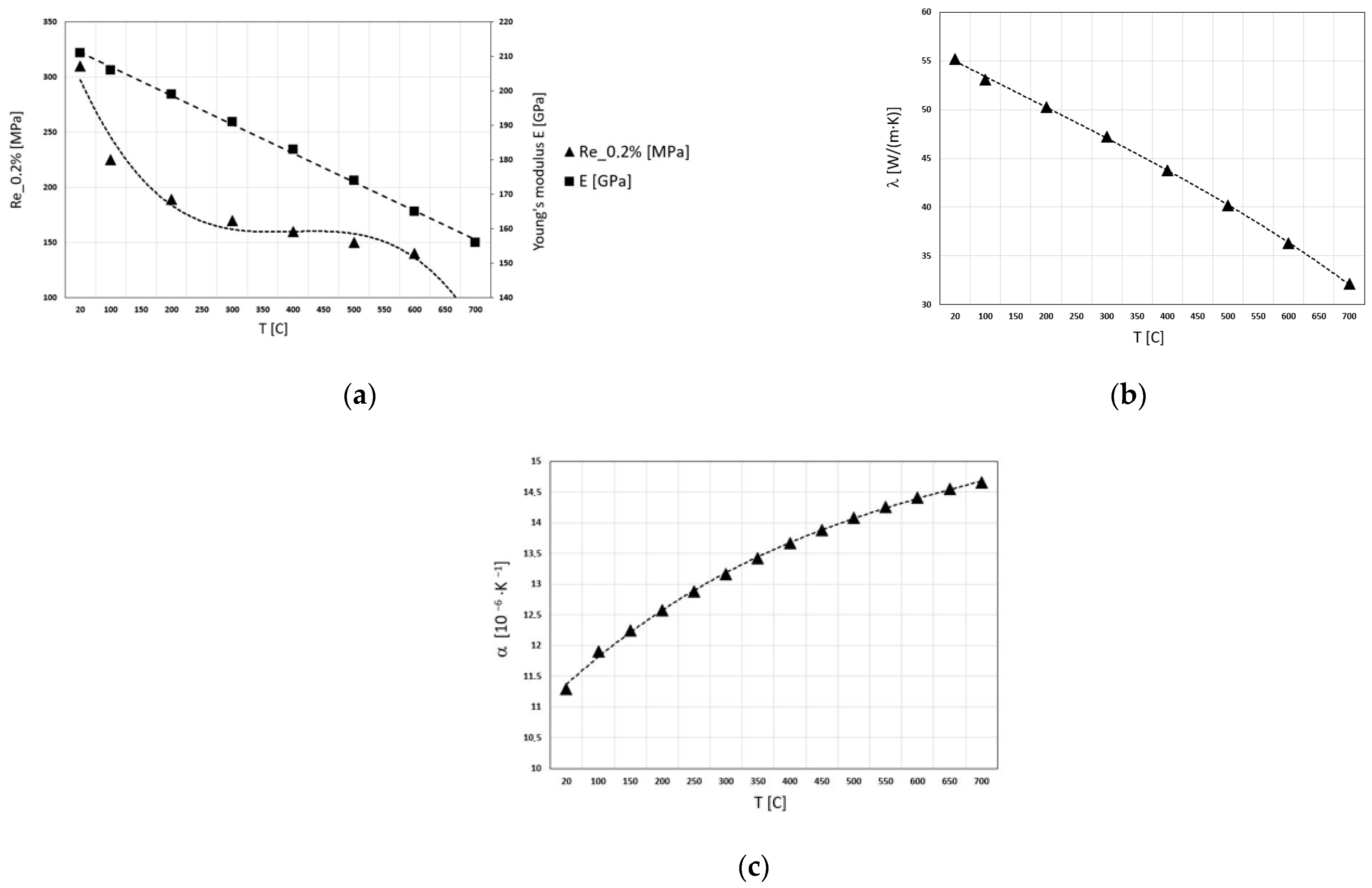
2K. The tubes are made of SA-178A carbon steel, which is equivalent to P235GH steel, whereas the fins are made of a material of a poorer quality, such as S235JR steel, with properties similar to P235GH steel. It is further assumed in the analysis that both the tubes and the fins are made of the same material. The temperature-dependent physical and strength properties of P235GH steel are shown in
Figure 4 [
19,
21].
The numerical analysis was conducted using the Ansys program [
22]. A representative fragment of the membrane wall was analysed (as shown in
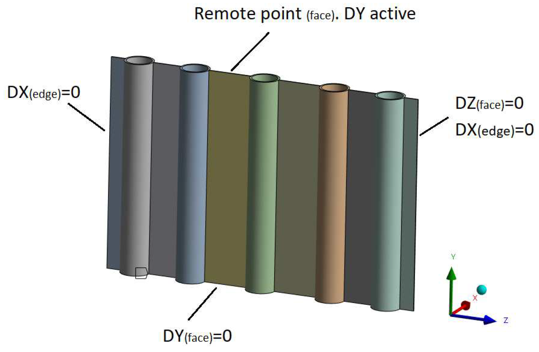
Figure 2, detail B), which also appears in other places of the boiler. Coupled fields were considered using the Transient Thermal and Static Structural modules. The analysed tight wall was built of SOLID-type elements in the Ansys program. In thermal analysis, the SOLID 278 type element was used, which has eight nodes with a single degree of freedom (temperature) at each node. This element is applicable to a 3-D, steady-state thermal analysis. In static structural analysis, the SOLID 278 element was replaced by the SOLID 185 structural element. This element has plasticity, stress stiffening, creep, large deflection, and large strain capabilities. For both thermal and structural analyses, appropriate boundary conditions were assumed at the cut-out locations (as shown in
Figure 5). On one side the wall is washed by flue gases, where a convective boundary condition is assumed, whereas on the other side the wall is insulated.
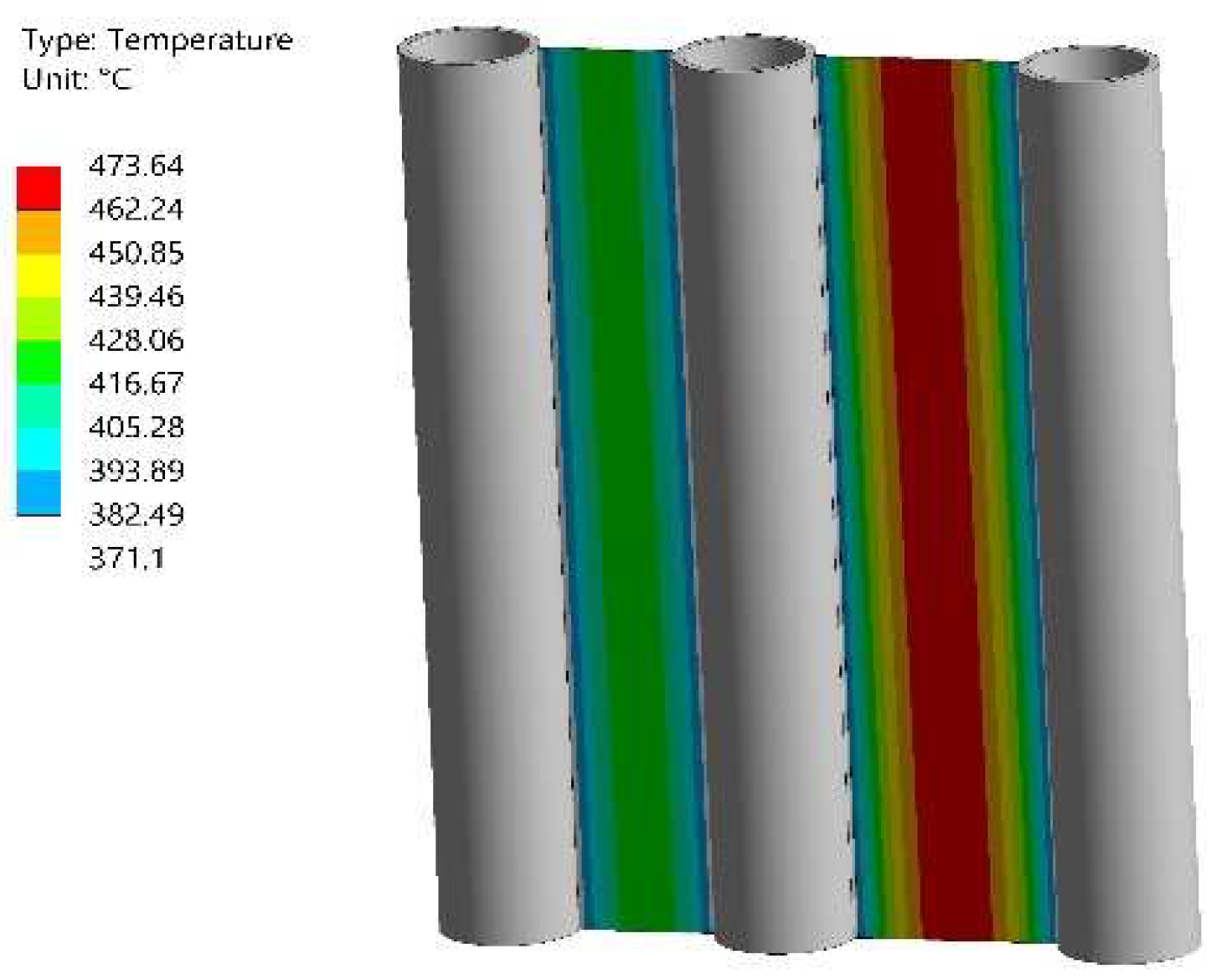
The temperature distribution results for the analysed fragment of the wall are shown in
Figure 6. The presented section of the wall includes two widths of the fins:
w = 76 mm and
w = 50 mm. Higher values of temperature occur in the wider fin. The highest temperature in the fin with width
w = 76 mm is 474 °C, whereas in the fin with width
w = 50 mm, the maximum temperature totals 425 °C. Such a temperature distribution affects the stresses arising in the fin.
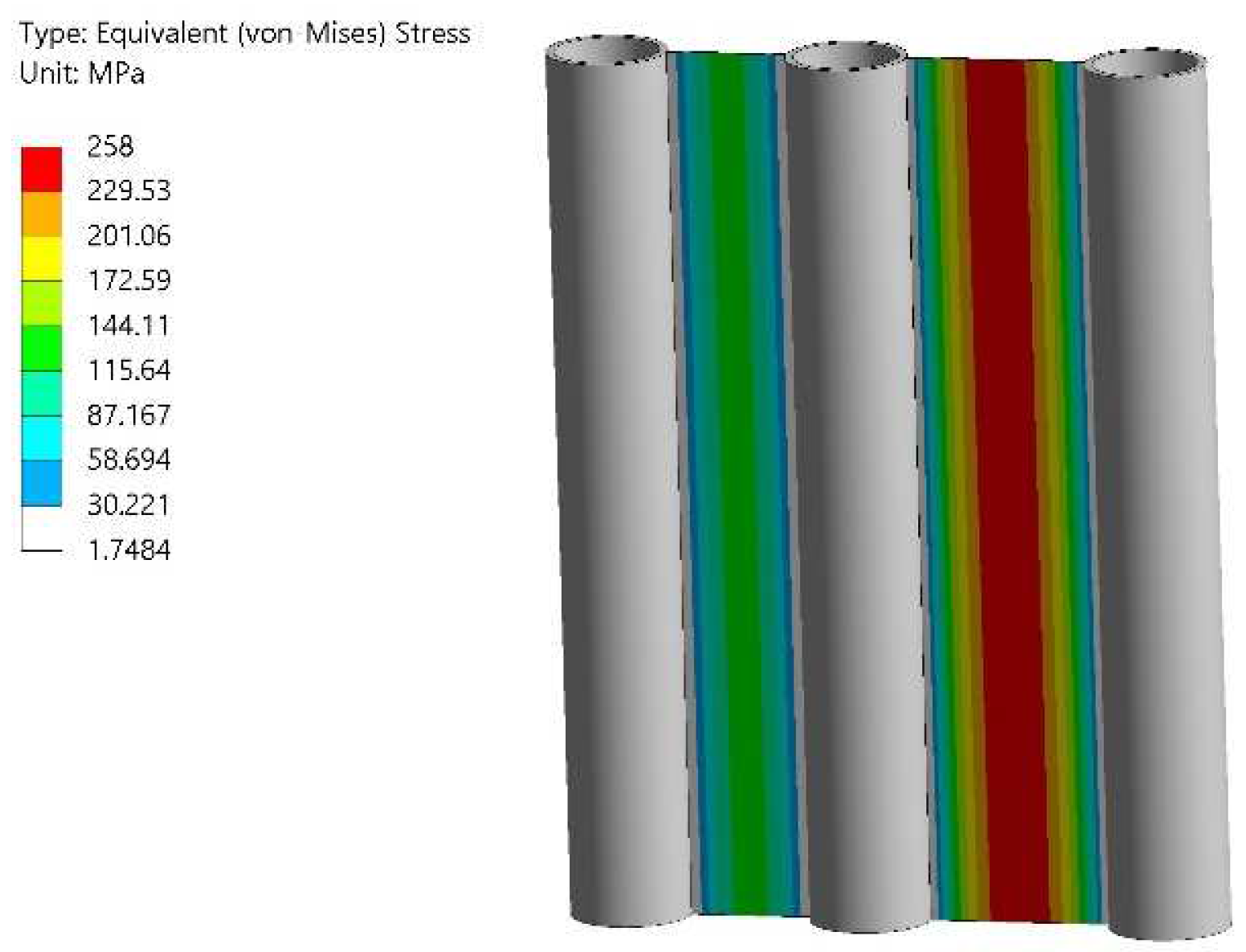
Figure 7 presents the distribution of stresses obtained in the linearly elastic analysis. At the temperature of 474 °C, the stresses in the wide fin considerably exceed the yield point.
The maximum equivalent (von Mises) stresses in the fin with width
w = 76 mm total 258 MPa, and the fin yield point in the temperature of 474 °C is 114 MPa. For the fin with width
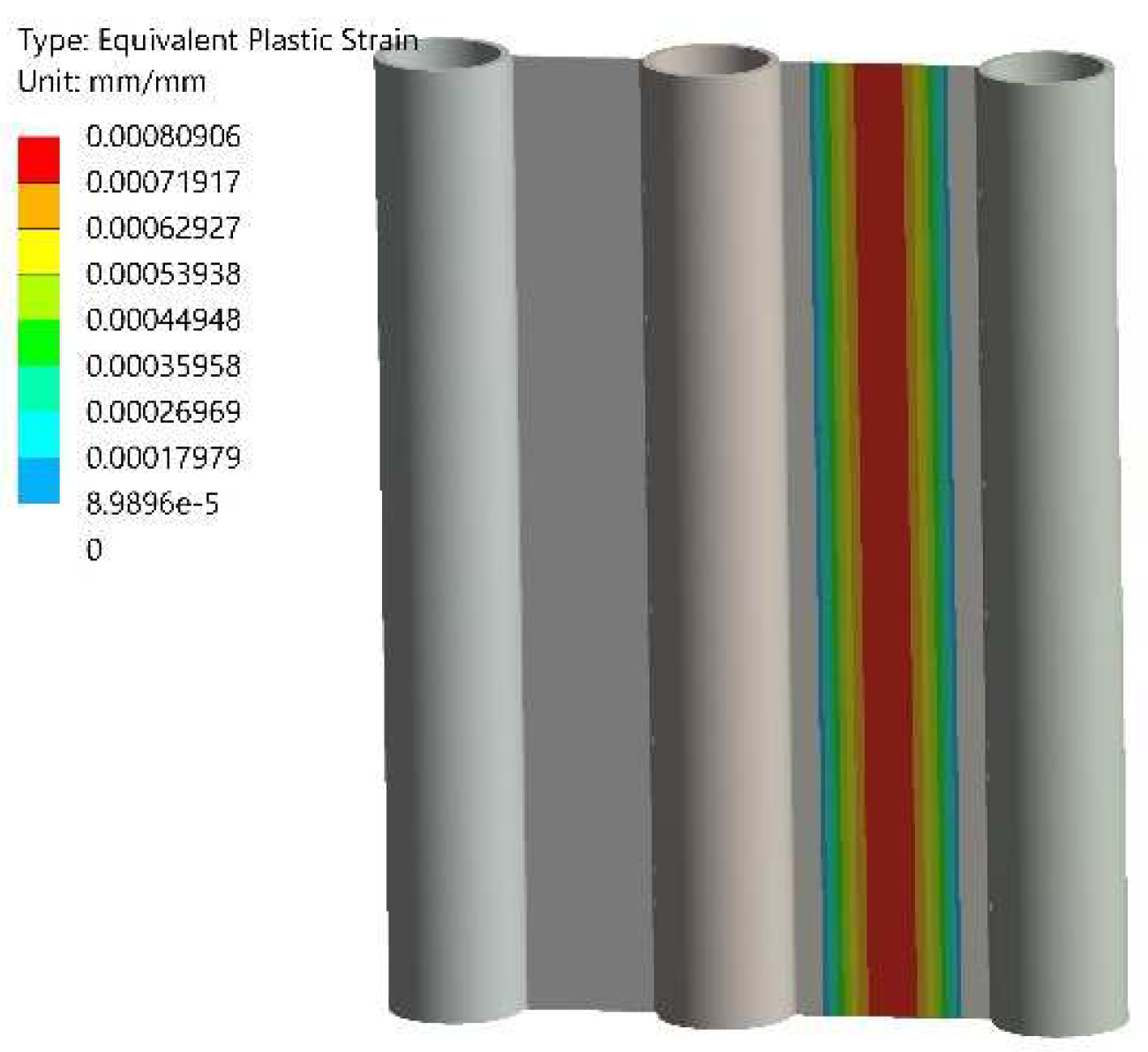
w = 50 mm, the maximum stress value is 127 MPa and the yield point is 120 MPa. Plastic strains arise in the wide fin. They are shown in
Figure 8. The elastic-plastic analyses were conducted based on the bilinear stress-strain model [
22,
23], which is also characterized by rate-independent plasticity. As a yield criterion, the von Mises condition was used, which was mathematically expressed as function
F (
σij, σY), where:
It should be noted that tensor
σij describes the stress state, whereas
σY is the yield point for a uniaxial state of tension or compression. The material behaviour is elastic when
F (
σij, σY) < 0; the yield function is satisfied when
F (
σij, σY) = 0 and undefined for
F (
σij, σY) > 0. In the context of materials that exhibit ductility, the effective stress (
σe) can be expressed using the distortion energy density criterion (von Mises). The equation describing this relationship is as follows:
The movement of the yield surface is directly dependent on the plastic strain increment. This is expressed by the flow rule, also known as plastic straining. The increment in plastic strain is defined as:
It is obtained by multiplying plastic multiplier λ by plastic potential gradient The plastic multiplier reflects the extent of plastic deformation, and its value varies depending on different loading conditions. In the context of the associative flow rule, which is a specific type of the flow rule related to bilinear isotropic hardening behaviour, the gradient of the plastic potential aligns itself perpendicularly to the yield surface. Since the plastic potential gradient is directional, the plastic strain increment is also normal to the yield surface.
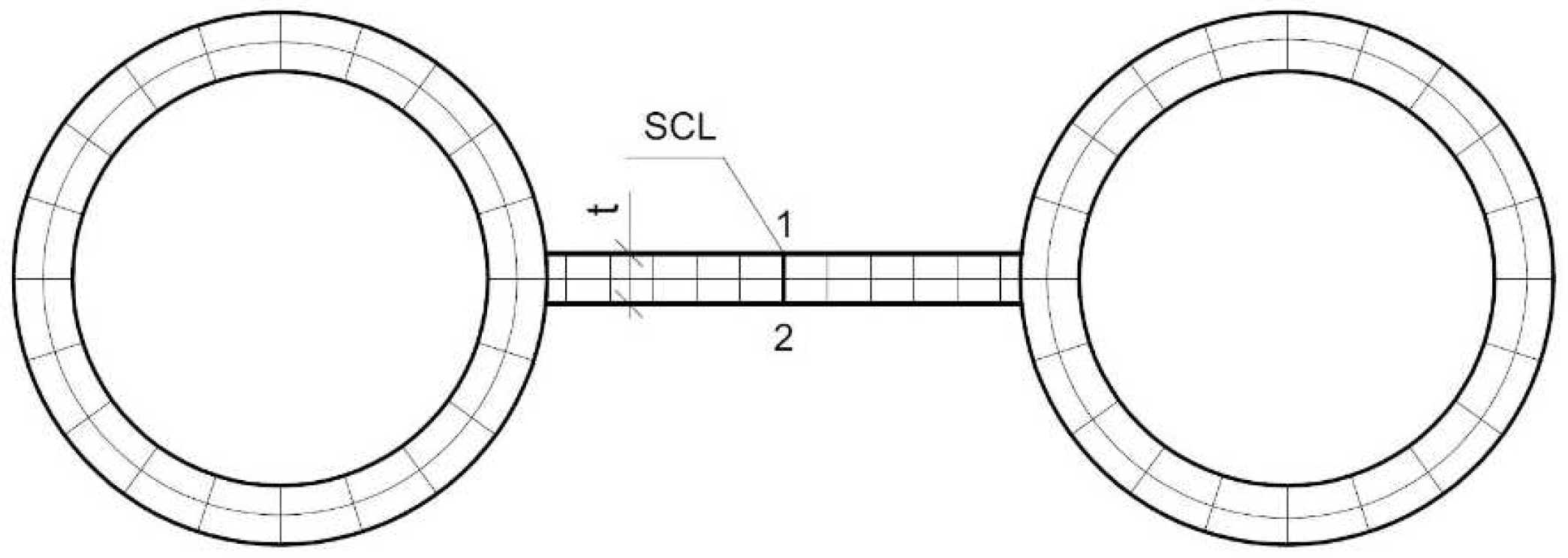
The field with the highest plasticization corresponds to places where the fins are longitudinally welded to each other during assembly (SCL [
1] line in
Figure 9). These welds are made as butt welds for full penetration, so as not to deteriorate the heat exchange process from the tubes to which they are welded. The largest total strain in the section indicated by SCL is 0.15%. Therefore, this region is particularly important when considering phenomena such as creep or low- and high-cycle loads.
Considering that boiler structures are affected by additional loads due to the lack of thermal compensation of other components and to the weight of the entire boiler structure, thermal stresses can significantly contribute to the damage of non-pressure boiler parts such as fins. Damage to the fin can indirectly involve stress concentration in the tube and thus trigger the same destruction mechanisms that acted in the fin.


