
Inverter-Fed Motor Drive System: A Systematic Analysis of Condition Monitoring and Practical Diagnostic Techniques

 , , ,
, , ,  ,
, 
Abstract
:1. Introduction
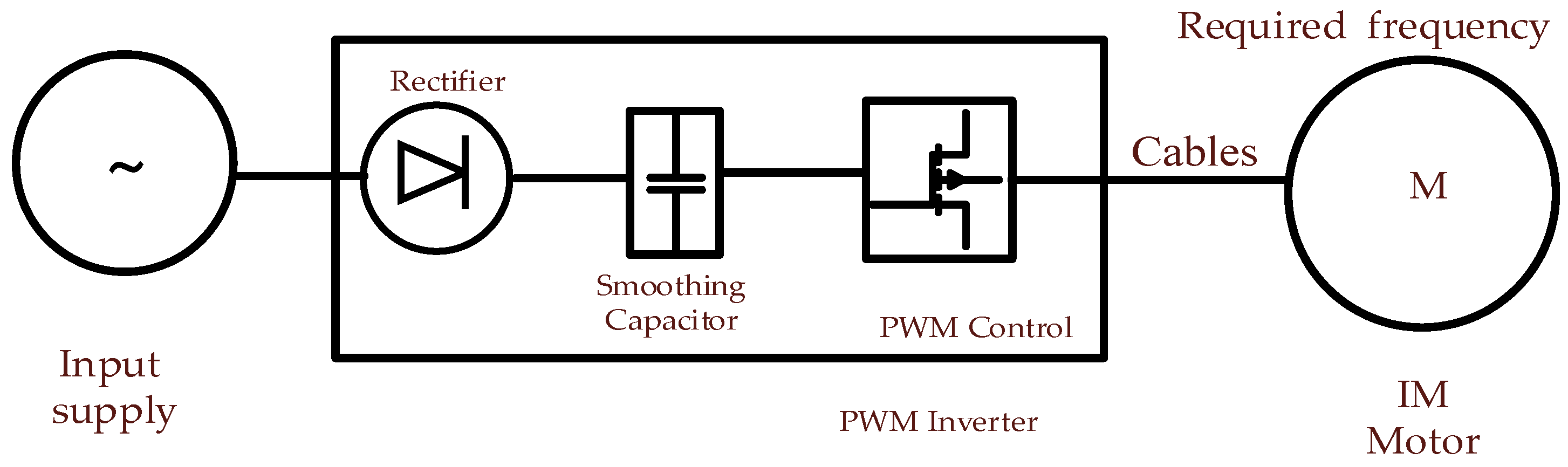
1.1. PWM Inverter-Fed Motor Drive System
1.2. Potential Challenges with Inverter-Fed Supply
2. Classification of Various Faults in Induction Motor
2.1. Fault Type Classification
2.2. Typical Faults with Inverter-Fed Induction Motor
3. Condition Monitoring and Diagnostic Techniques
3.1. Common Condition Monitoring Techniques
- Motor current signature analysis (MCSA) [66];
- Voltage signature analysis (VSA) [67];
- Extended Park vector approach (EPVA) [68];
- Instantaneous power signature analysis (IPSA) [69];
- State monitoring analysis like temperature, noise, speed fluctuation, magnetic flux;
- Condition Monitoring Sensors:
- Vibration sensors: accelerometers, proximity probes;
- Temperature sensors: thermocouples, resistance temperature detectors;
- Current sensors: Hall effect sensors, current transformers;
- Acoustic sensors: microphones, ultrasonic sensors;
- Emissions-based monitoring;
- Partial discharge and surge testing;
- Motor circuit analysis.
3.2. Latest Trends in Condition Monitoring for IM Faults
3.3. CM Implementation Strategy
4. Fault Monitoring and Diagnosis of Induction Motor
4.1. IM Stator’s Faults
4.1.1. Classification of the Stator Fault
- Laminations that create a hotspot in the core and cause slackening in the core.
- Faults in the frame due to unbalanced vibration, circulating current within it due to shaft voltages, coolant loss, or a potential earth fault.
- Faults in the end portion, insulation fretting, insulation contamination by moisture, oil, or dirt, damage to connectors, cracking of insulation, discharge erosion of insulation, and the displacement of conductors.
- Faults in portions from the slot due to the misplacement of conductors.
4.1.2. Inter-Turn Short-Circuit Faults
4.1.3. Current Harmonics Due to Stator ITSC Fault
4.1.4. II-Level Inverter’s Current Harmonics
4.2. Rotor Faults
- Broken rotor bars (BRB);
- Rotor bar displacement;
- Rotor bar eccentricity;
- Rotor end ring damage;
- Rotor core faults and overheating;
- Rotor skewing issues;
- Rotor short circuits.
4.3. Bearing Faults
- The rotor vibrates heavily and increases the fatigue stress due to high output load torque;
- Loss of lubrication brought on by a shaft voltage;
- A high bearing current result in the heat that the shaft can conduct.
4.4. Air-Gap Eccentricity Faults
- Static eccentricity (SE);
- Dynamic eccentricity (DE);
- Mixed eccentricity (ME).
4.5. Common-Mode Voltage (CMV) and Bearing Current Faults
- The voltage at the equipment terminals is doubled because of reflections, putting extra strain on the windings’ insulation.
- In windings, capacitive currents and non-uniform voltage distribution can cause electrical machines to experience a circulating current nominated as a bearing current.
- Charges stored in the ground capacitors.
4.5.1. Common-Mode Voltage (CMV)
- The voltage at the equipment terminals is doubled because of reflections, putting extra strain on the windings’ insulation.
- In windings, capacitive currents and non-uniform voltage distribution can cause electrical machines to experience a circulating current nominated as a bearing current.
- Charges are stored in the ground capacitors.
- Capacitive BC,
- Non-circulating BC,
- Circulating BC (electric discharge machining),
- Current in rotor-ground.
4.5.2. Diagnostic of Bearing Currents Faults
4.6. Partial Discharge (PD)
5. Intelligent Diagnostic Techniques
- Decomposition methods of the signal,
- Statistical time-based feature prediction,
- Genetic algorithm (GA) optimization based on the feature,
- Component analysis based on integrating principal,
- Selection procedure based on the feature,
- Selection based on the Fisher score,
- Extraction of the feature.
- Adaptive neuro-fuzzy inference systems (ANFIS),
- Fuzzy wavelet logic,
- Wavelet packet transform (WPT),
- Support vector machine (SVM).
6. Summary and Future Directions
- FD in IM fed with high-frequency PWM inverter:Research into the impact of high-frequency PWM switching on the motor insulation, partial discharge impacts, bearing mechanical faults, common-mode voltage adverse effects, and other components, and to foster techniques to detect and diagnose faults specifically related to the PWM operation.
- Sensor-less fault detection techniques:Analyze some of the advanced sensorless FD techniques that can be used to supervise the condition and identify the faults in IM, without relying on additional usages of the sensor’s entity, without much complexity, and overall cost of FD strategic implementation,
- FD with machine learning (ML):This area highlights the investigation related to applying machine learning algorithms, such as deep learning or reinforcement learning, with improved models of high accuracy in IM operated by high PWM inverters.
- FD in multi-level inverters:This is also a potential research area to study the impact of multi-level PWM inverters on motor operation, output performance, transient response caused to load changes, operation in high-speed environments, and flux weaken range, while operating in wide-beyond speed, tailored to the characteristics of multi-level modulation techniques.
- Condition monitoring in harsh environments:Development of robust fault diagnostic technique suitable for IM operated in harsh environments, such as in the zone of extremely high temperature, high humidity, contaminated environments, and the high duty cycle of operation, which create indigenous faults within IM. The robustness defines the compactness of the algorithm or FD techniques, which shows insensitivity in its output, with some changes in input-sensitive parameters. The probability of robustness can be analyzed through different statical analyses and analytical techniques, especially in the time domain signal analysis that include RMS value, standard deviation, skewness, kurtosis, high statical moments. It can be enhanced with optimization algorithms, such as particle swarm optimization, genetic algorithms, and other naturally inspired algorithms.
- IoT for remote access:The most feasible and influential process can be implemented by exploring the IoT integration techniques with FD. Real-time remote monitoring of IM operated by a high transient inverter allows continuous time monitoring and early detection from anywhere.
- Model-based predictive maintenance:For this type of FD, state-of-the-art, physics-based IM models; real-time sensor instrumentation; and measurement capability can be utilized to establish a FD scheme for predictive maintenance strategy. For the high-performance output of FD technique, the maintenance schedule can be optimized to minimize the IM motor’s downtime.
- FD in mechanical faults:Examine methods for fault identification and diagnosis in bearing, e.g., outer, inner race, and roller fault. Examples of rotor faults include broken rotor (BRB) faults and eccentricity. It is necessary to consider the one-of-a-kind difficulties and negative impact that high-PWM inverters present.
- Online-parameter estimation:Developing the online-parameter estimation methods to accurately access the motor parameters, which can detect the fault and generate a potentially viable solution for FD. These parameters are resistance, inductances, load torque, and speed response, which vary with IM operation and employ monitoring criteria and algorithms for the FD.
- Hybrid FD techniques:A good combination of numerous techniques, such as advanced signal processing techniques, artificial intelligence, machine learning, and model-based techniques, can be used to create a hybrid FD approach that can improve overall performance and reliability by taking advantage of the strengths inherent in each diagnostic procedure.
7. Conclusions
Author Contributions
Funding
Data Availability Statement
Acknowledgments
Conflicts of Interest
References
- Venkatar Ramana, D.; Baskar, S. Fault Analysis of Voltage Source Inverter Fed Induction Motor Drive. In Proceedings of the 2016 IEEE International Conference on Computational Intelligence and Computing Research, ICCIC 2016, Chennai, India, 15–17 December 2016. [Google Scholar]
- Soufi, Y.; Bahi, T.; Harkat, M.F.; Rouaibia, R. Diagnosis and Fault Detection in Induction Motor Drive Fed by PWM Voltage Source Inverter. J. Electr. Syst. 2010, 6, 2. [Google Scholar]
- Vaimann, T.; Belahcen, A.; Martinez, J.; Kilk, A. Detection of Broken Bars in Frequency Converter Fed Induction Motor Using Park’s Vector Approach. In Proceedings of the PQ 2012: 8th International Conference—2012 Electric Power Quality and Supply Reliability, Tartu, Estonia, 11–13 July 2012. [Google Scholar]
- Asad, B.; Vaimann, T.; Kallaste, A.; Rassolkin, A.; Belahcen, A. Winding Function Based Analytical Model of Squirrel Cage Induction Motor for Fault Diagnostics. In Proceedings of the 2019 26th International Workshop on Electric Drives: Improvement in Efficiency of Electric Drives, IWED 2019, Moscow, Russia, 30 January–February 2019. [Google Scholar]
- Vaimann, T.; Kallaste, A.; Kilk, A. Sensorless Detection of Induction Motor Rotor Faults Using the Clarke Vector Approach. Sci. J. Riga Tech. Univ. Power Electr. Eng. 2011, 28, 2011. [Google Scholar] [CrossRef] [Green Version]
- Asad, B.; Vaimann, T.; Belahcen, A.; Kallaste, A.; Rassõlkin, A.; Iqbal, M.N. Modified Winding Function-Based Model of Squirrel Cage Induction Motor for Fault Diagnostics. IET Electr. Power Appl. 2020, 14, 1722–1734. [Google Scholar] [CrossRef]
- Vaimann, T.; Sobra, J.; Belahcen, A.; Rassõlkin, A.; Rolak, M.; Kallaste, A. Induction Machine Fault Detection Using Smartphone Recorded Audible Noise. IET Sci. Meas. Technol. 2018, 12, 554–560. [Google Scholar] [CrossRef] [Green Version]
- Rassõlkin, A.; Vaimann, T.; Belahcen, A.; Kallaste, A.; Petrov, A.; Plokhov, I.; Kotelnikov, A. Adjusted Electrical Equivalent Circuit Model of Induction Motor with Broken Rotor Bars. In Proceedings of the 10th International Conference—2016 Electric Power Quality and Supply Reliability, PQ 2016, Tallinn, Estonia, 29–31 August 2016. [Google Scholar]
- Asad, B.; Vaimann, T.; Belahcen, A.; Kallaste, A.; Rassõlkin, A.; Ghafarokhi, P.S.; Kudelina, K. Transient Modeling and Recovery of Non-Stationary Fault Signature for Condition Monitoring of Induction Motors. Appl. Sci. 2021, 11, 2806. [Google Scholar] [CrossRef]
- Asad, B.; Vaimann, T.; Belahcen, A.; Kallaste, A.; Rassolkin, A.; Van Khang, H.; Ghahfarokhi, P.S.; Naseer, M.U.; Iqbal, M.N. The Modeling and Investigation of Slot Skews and Supply Imbalance on the Development of Principal Slotting Harmonics in Squirrel Cage Induction Machines. IEEE Access 2021, 9, 165932–165946. [Google Scholar] [CrossRef]
- Asad, B.; Vaimann, T.; Belahcen, A.; Kallaste, A.; Rassolkin, A. Rotor Fault Diagnostic of Inverter Fed Induction Motor Using Frequency Analysis. In Proceedings of the 2019 IEEE 12th International Symposium on Diagnostics for Electrical Machines, Power Electronics and Drives, SDEMPED 2019, Toulouse, France, 27–30 August 2019. [Google Scholar]
- Zhu, W.; De Gaetano, D.; Chen, X.; Jewell, G.W.; Hu, Y. A Review of Modeling and Mitigation Techniques for Bearing Currents in Electrical Machines with Variable-Frequency Drives. IEEE Access 2022, 10, 125279–125297. [Google Scholar] [CrossRef]
- Oikonomou, N.; Holtz, J. Closed-Loop Control of Medium-Voltage Drives Operated with Synchronous Optimal Pulsewidth Modulation. IEEE Trans. Ind. Appl. 2008, 44, 115–123. [Google Scholar] [CrossRef]
- Napoles, J.; Leon, J.I.; Portillo, R.; Franquelo, L.G.; Aguirre, M.A. Selective Harmonic Mitigation Technique for High-Power Converters. IEEE Trans. Ind. Electron. 2010, 57, 2315–2323. [Google Scholar] [CrossRef]
- Zhang, Y.; Zhao, Z.; Zhu, J. A Hybrid PWM Applied to High-Power Three-Level Inverter-Fed Induction-Motor Drives. IEEE Trans. Ind. Electron. 2011, 58, 3409–3420. [Google Scholar] [CrossRef]
- Vargas, R.; Ammann, U.; Rodríguez, J.; Pontt, J. Reduction of Switching Losses and Increase in Efficiency of Power Converters Using Predictive Control. In Proceedings of the PESC Record—IEEE Annual Power Electronics Specialists Conference, Rhodes, Greece, 15–19 June 2008. [Google Scholar]
- Kerszenbaum, I. Shaft Currents in Electric Machines Fed by Solid-State Drives. In Proceedings of the IEEE Conference Record of Industrial and Commercial Power Systems Technical Conference, Pittsburgh, PA, USA, 4–7 May 1992. [Google Scholar]
- Rosales, A.; Sarikhani, A.; Mohammed, O.A. Evaluation of Radiated Electromagnetic Field Interference Due to Frequency Swithcing in PWM Motor Drives by 3D Finite Elements. IEEE Trans. Magn. 2011, 47, 1474–1477. [Google Scholar] [CrossRef]
- Lee, K.; Shen, G.; Yao, W.; Lu, Z. Performance Characterization of Random Pulse Width Modulation Algorithms in Industrial and Commercial Adjustable-Speed Drives. IEEE Trans. Ind. Appl. 2017, 53, 1078–1087. [Google Scholar] [CrossRef]
- Kim, T.H.; Lee, J. Comparison of the Iron Loss of a Flux-Reversal Machine under Four Different PWM Modes. IEEE Trans. Magn. 2007, 43, 1725–1728. [Google Scholar] [CrossRef]
- Jung, H.S.; Hwang, C.E.; Kim, H.S.; Sul, S.K.; Hee-Won, A.; Yoo, H. Minimum Torque Ripple Pulse Width Modulation with Reduced Switching Frequency for Medium-Voltage Motor Drive. IEEE Trans. Ind. Appl. 2018, 54, 3315–3325. [Google Scholar] [CrossRef]
- Rajkamal, R.; Karthi, A. Analysis of PWM Techniques for Inverters Driving AC Motors. Pertanika J. Sci. Technol. 2017, 25, 1211–1222. [Google Scholar]
- Lavanya, S.N.; Reddy, T.B.; Kumar, M.V. Performance of Random PWM Techniques for Induction Motor Drive. Int. J. Eng. Adv. Technol. 2019, 8, 133–139. [Google Scholar]
- Chen, S.; Lipo, T.A.; Fitzgerald, D. Modeling of Motor Bearing Currents in PWM Inverter Drives. IEEE Trans. Ind. Appl. 1996, 32, 1365–1370. [Google Scholar] [CrossRef] [Green Version]
- Hamman, J.; Van Der Merwe, F.S. Voltage Harmonics Generated by Voltage-Fed Inverters Using PWM Natural Sampling. IEEE Trans. Power Electron. 1988, 3, 297–302. [Google Scholar] [CrossRef]
- Persson, E. Transient Effects in Application of PWM Inverters to Induction Motors. IEEE Trans. Ind. Appl. 1992, 28, 1095–1101. [Google Scholar] [CrossRef]
- Chen, S.; Lipo, T.A.; Fitzgerald, D. Source of Induction Motor Bearing Currents Caused by PWM Inverters. IEEE Trans. Energy Convers. 1996, 11, 25–32. [Google Scholar] [CrossRef]
- Soufi, Y.; Bahi, T.; Harkat, M.F.; Mohammedi, M. Fault Diagnosis Methods for Three Phase PWM Inverter Fed Induction Motor. Int. J. Eng. Appl. 2018, 6, 122. [Google Scholar] [CrossRef]
- Sundeep, S.; Wang, J.; Griffo, A.; Alvarez-Gonzalez, F. Peak Voltage Stress on Stator Winding in PWM Inverter Fed Drives. In Proceedings of the 2020 International Conference on Electrical Machines, ICEM 2020, Gothenburg, Sweden, 23–26 August 2020. [Google Scholar]
- Esmaeli, A.; Tavassoli, F. A Novel Passive Filter to Reduce PWM Inverters Adverse Effects in Electrical Machine System. World Appl. Sci. J. 2011, 13, 2536–2544. [Google Scholar]
- Benbouzid, M.E.H.; Vieira, M.; Theys, C. Induction Motors’ Faults Detection and Localization Using Stator Current Advanced Signal Processing Techniques. IEEE Trans. Power Electron. 1999, 14, 14–22. [Google Scholar] [CrossRef]
- Benbouzid, M.E.H. A Review of Induction Motors Signature Analysis as a Medium for Faults Detection. IEEE Trans. Ind. Electron. 2000, 47, 984–993. [Google Scholar] [CrossRef] [Green Version]
- Albrecht, P.F.; Appiarius, J.C.; McCoy, R.M.; Owen, E.L.; Sharma, D.K. Assessment of the Reliability of Motors in Utility Applications—Updated. IEEE Trans. Energy Convers. 1986, EC-1, 39–46. [Google Scholar] [CrossRef]
- Choudhary, A.; Goyal, D.; Shimi, S.L.; Akula, A. Condition Monitoring and Fault Diagnosis of Induction Motors: A Review. Arch. Comput. Methods Eng. 2019, 26, 1221–1238. [Google Scholar] [CrossRef]
- Vaimann, T.; Belahcen, A.; Kallaste, A. Necessity for Implementation of Inverse Problem Theory in Electric Machine Fault Diagnosis. In Proceedings of the SDEMPED 2015: IEEE 10th International Symposium on Diagnostics for Electrical Machines, Power Electronics and Drives, Guarda, Portugal, 1–4 September 2015. [Google Scholar]
- Akhil Vinayak, B.; Anjali Anand, K.; Jagadanand, G. Wavelet-Based Real-Time Stator Fault Detection of Inverter-Fed Induction Motor. IET Electr. Power Appl. 2020, 14, 82–90. [Google Scholar] [CrossRef]
- Skowron, M.; Orlowska-Kowalska, T.; Wolkiewicz, M.; Kowalski, C.T. Convolutional Neural Network-Based Stator Current Data-Driven Incipient Stator Fault Diagnosis of Inverter-Fed Induction Motor. Energies 2020, 13, 1475. [Google Scholar] [CrossRef] [Green Version]
- Asad, B.; Vaimann, T.; Kallaste, A.; Belahcen, A. Harmonic Spectrum Analysis of Induction Motor with Broken Rotor Bar Fault. In Proceedings of the 2018 IEEE 59th Annual International Scientific Conference on Power and Electrical Engineering of Riga Technical University, RTUCON 2018, Riga, Latvia, 12–13 November 2018. [Google Scholar]
- Martin-Diaz, I.; Morinigo-Sotelo, D.; Duque-Perez, O.; Arredondo-Delgado, P.A.; Camarena-Martinez, D.; Romero-Troncoso, R.J. Analysis of Various Inverters Feeding Induction Motors with Incipient Rotor Fault Using High-Resolution Spectral Analysis. Electr. Power Syst. Res. 2017, 152, 18–26. [Google Scholar] [CrossRef]
- Kudelina, K.; Vaimann, T.; Rassõlkin, A.; Kallaste, A.; Demidova, G.; Karpovich, D. Diagnostic Possibilities of Induction Motor Bearing Currents. In Proceedings of the 2021 18th International Scientific Technical Conference Alternating Current Electric Drives, ACED 2021, Ekaterinburg, Russia, 24–27 May 2021. [Google Scholar]
- Kudelina, K.; Vaimann, T.; Rassolkin, A.; Kallaste, A.; Asad, B.; Demidova, G. Induction Motor Bearing Currents-Causes and Damages. In Proceedings of the 2021 28th International Workshop on Electric Drives: Improving Reliability of Electric Drives, IWED 2021, Moscow, Russia, 27–29 January 2021. [Google Scholar]
- Kudelina, K.; Asad, B.; Vaimann, T.; Rassolkin, A.; Kallaste, A. Effect of Bearing Faults on Vibration Spectrum of BLDC Motor. In Proceedings of the 2020 IEEE Open Conference of Electrical, Electronic and Information Sciences, eStream 2020, Vilnius, Lithuania, 30 April 2020. [Google Scholar]
- Kudelina, K.; Autsou, S.; Asad, B.; Vaimann, T.; Rassolkin, A.; Kallaste, A. Implementation and Analysis of Rolling Bearing Faults Caused by Shaft Currents. In Proceedings of the International Workshop on Electric Drives, IWED, Moscow, Russia, 26–29 January 2022; Volume 2022. [Google Scholar]
- De Paula, H.; de Andrade, D.A.; Chaves, M.L.R.; Domingos, J.L.; de Freitas, M.A.A. Methodology for Cable Modeling and Simulation for High-Frequency Phenomena Studies in PWM Motor Drives. IEEE Trans. Power Electron. 2008, 23, 744–752. [Google Scholar] [CrossRef]
- Garcia-Perez, A.; Romero-Troncoso, R.J.; Cabal-Yepez, E.; Osornio-Rios, R.A.; Lucio-Martinez, J.A. Application of High-Resolution Spectral Analysis for Identifying Faults in Induction Motors by Means of Sound. JVC/J. Vib. Control 2012, 18, 1585–1594. [Google Scholar] [CrossRef]
- Xu, Y.; Liang, Y.; Yuan, X.; Wu, X.; Li, Y. Experimental Assessment of High Frequency Bearing Currents in an Induction Motor Driven by a SiC Inverter. IEEE Access 2021, 9, 40540–40549. [Google Scholar] [CrossRef]
- Chen, H.; Zhao, H. Review on Pulse-Width Modulation Strategies for Common-Mode Voltage Reduction in Three-Phase Voltage-Source Inverters. IET Power Electron. 2016, 9, 2611–2620. [Google Scholar] [CrossRef]
- Erdman, J.M.; Kerkman, R.J.; Schlegel, D.W.; Skibinski, G.L. Effect of PWM Inverters on Ac Motor Bearing Currents and Shaft Voltages. IEEE Trans. Ind. Appl. 1996, 32, 250–259. [Google Scholar] [CrossRef]
- Huang, Y.; Xu, Y.; Zhang, W.; Zou, J. Modified Single-Edge SVPWM Technique to Reduce the Switching Losses and Increase PWM Harmonics Frequency for Three-Phase VSIs. IEEE Trans Power Electron 2020, 35, 10643–10653. [Google Scholar] [CrossRef]
- Kumar, S.; Mukherjee, D.; Guchhait, P.K.; Banerjee, R.; Srivastava, A.K.; Vishwakarma, D.N.; Saket, R.K. A Comprehensive Review of Condition Based Prognostic Maintenance (CBPM) for Induction Motor. IEEE Access 2019, 7, 90690–90704. [Google Scholar] [CrossRef]
- Cabanas, M.F.; Norniella, J.G.; Melero, M.G.; Rojas, C.H.; Cano, J.M.; Pedrayes, F.; Orcajo, G.A. Detection of Stator Winding Insulation Failures: On-Line and off-Line Tests. In Proceedings of the 2013 IEEE Workshop on Electrical Machines Design, Control and Diagnosis, WEMDCD 2013, Paris, France, 11–12 March 2013. [Google Scholar]
- Unsal, A.; Kara, O. Modeling of Broken Rotor Bars in a Squirrel-Cage Induction Motor. In Proceedings of the International Conference on Power Engineering, Energy and Electrical Drives, Istanbul, Turkey, 13–17 May 2013. [Google Scholar]
- Han, P.; Zhang, Y.; Kesgin, M.G.; Heins, G.; Patterson, D.; Thiele, M.; Ionel, D.M. On the Modeling of Bearing Voltage and Current in PWM Converter-Fed Electric Machines Using Electromagnetic Finite Element Analysis. In Proceedings of the 2021 IEEE Energy Conversion Congress and Exposition, ECCE 2021, Virtual, 10–14 October 2021. [Google Scholar]
- Yamazaki, K.; Iida, K.; Terai, Y. Fast Estimation of Harmonic Losses Caused by Inverter Carrier in Interior Permanent-Magnet Synchronous Motors by Using Combination of Time- And Frequency-Domain Finite-Element Analyses. IEEE Trans. Magn. 2020, 56, 1–4. [Google Scholar] [CrossRef]
- Prieto, J.; Jones, M.; Barrero, F.; Levi, E.; Toral, S. Comparative Analysis of Discontinuous and Continuous PWM Techniques in VSI-Fed Five-Phase Induction Motor. IEEE Trans. Ind. Electron. 2011, 58, 5324–5335. [Google Scholar] [CrossRef]
- Holmes, D.G.; Lipo, T.A. Pulse Width Modulation for Power Converters; John Wiley & Sons: Hoboken, NJ, USA, 2010. [Google Scholar]
- Nandi, S.; Toliyat, H.A.; Li, X. Condition Monitoring and Fault Diagnosis of Electrical Motors—A Review. IEEE Trans. Energy Convers. 2005, 20, 719–729. [Google Scholar] [CrossRef]
- Asad, B.; Vaimann, T.; Belahcen, A.; Kallaste, A. Broken Rotor Bar Fault Diagnostic of Inverter Fed Induction Motor Using FFT, Hilbert and Park’s Vector Approach. In Proceedings of the 2018 23rd International Conference on Electrical Machines, ICEM 2018, Alexandroupoli, Greece, 3–6 September 2018. [Google Scholar]
- Dorrell, D.G.; Makhoba, K. Detection of Inter-Turn Stator Faults in Induction Motors Using Short-Term Averaging of Forward and Backward Rotating Stator Current Phasors for Fast Prognostics. IEEE Trans. Magn. 2017, 53, 1–7. [Google Scholar] [CrossRef]
- Devi, N.R.; Siva Sarma, D.V.S.S.; Ramana Rao, P.V. Detection of Stator Incipient Faults and Identification of Faulty Phase in Three-Phase Induction Motor—Simulation and Experimental Verification. IET Electr. Power Appl. 2015, 9, 540–548. [Google Scholar] [CrossRef]
- Tallam, R.M.; Lee, S.B.; Stone, G.C.; Kliman, G.B.; Yoo, J.; Habetler, T.G.; Harley, R.G. A Survey of Methods for Detection of Stator-Related Faults in Induction Machines. IEEE Trans. Ind. Appl. 2007, 43, 920–933. [Google Scholar] [CrossRef]
- Jung, J.; Park, Y.; Lee, S.B.; Cho, C.; Kim, K.; Wiedenbrug, E.; Teska, M. Monitoring of Journal Bearing Faults Based on Motor Current Signature Analysis for Induction Motors. In Proceedings of the 2015 IEEE Energy Conversion Congress and Exposition, ECCE 2015, Montreal, QC, Canada, 20–24 September 2015. [Google Scholar]
- Mirzaeva, G.; Saad, K.I. Advanced Diagnosis of Stator Turn-to-Turn Faults and Static Eccentricity in Induction Motors Based on Internal Flux Measurement. IEEE Trans. Ind. Appl. 2018, 54, 3961–3970. [Google Scholar] [CrossRef]
- Asad, B.; Eensalu, L.; Vaimann, T.; Kallaste, A.; Rassolkin, A.; Belahcen, A. The FEM Based Modeling and Corresponding Test Rig Preparation for Broken Rotor Bars Analysis. In Proceedings of the 2019 IEEE 60th Annual International Scientific Conference on Power and Electrical Engineering of Riga Technical University, RTUCON 2019, Riga, Latvia, 7–9 October 2019. [Google Scholar]
- Shirazian, S.; Alibabaei, M. Using Neural Networks Coupled with Particle Swarm Optimization Technique for Mathematical Modeling of Air Gap Membrane Distillation (AGMD) Systems for Desalination Process. Neural Comput. Appl. 2017, 28, 2099–2104. [Google Scholar] [CrossRef]
- Halder, S.; Bhat, S.; Zychma, D.; Sowa, P. Broken Rotor Bar Fault Diagnosis Techniques Based on Motor Current Signature Analysis for Induction Motor—A Review. Energies 2022, 15, 8569. [Google Scholar] [CrossRef]
- Duque-Perez, O.; Garcia-Escudero, L.A.; Morinigo-Sotelo, D.; Gardel, P.E.; Perez-Alonso, M. Analysis of Fault Signatures for the Diagnosis of Induction Motors Fed by Voltage Source Inverters Using ANOVA and Additive Models. Electr. Power Syst. Res. 2015, 121, 1–13. [Google Scholar] [CrossRef]
- Vilhekar, T.G.; Ballal, M.S.; Suryawanshi, H.M. Application of Multiple Parks Vector Approach for Detection of Multiple Faults in Induction Motors. J. Power Electron. 2017, 17, 972–982. [Google Scholar] [CrossRef]
- Maouche, Y.; Oumaamar, M.E.K.; Boucherma, M.; Khezzar, A. Instantaneous Power Spectrum Analysis for Broken Bar Fault Detection in Inverter-Fed Six-Phase Squirrel Cage Induction Motor. Int. J. Electr. Power Energy Syst. 2014, 62, 110–117. [Google Scholar] [CrossRef]
- Braham, A.; Lachiri, Z. Diagnosis of Broken Bar Fault in Induction Machines Using Advanced Digital Signal Processing. Int. Rev. Electr. Eng. 2010, 5. [Google Scholar] [CrossRef]
- Gangsar, P.; Tiwari, R. Signal Based Condition Monitoring Techniques for Fault Detection and Diagnosis of Induction Motors: A State-of-the-Art Review. Mech. Syst. Signal Process. 2020, 144, 106908. [Google Scholar] [CrossRef]
- Yakhni, M.F.; Cauet, S.; Sakout, A.; Assoum, H.; Etien, E.; Rambault, L.; El-Gohary, M. Variable Speed Induction Motors’ Fault Detection Based on Transient Motor Current Signatures Analysis: A Review. Mech. Syst. Signal Process. 2023, 184. [Google Scholar] [CrossRef]
- Lin, C.K.; Liu, T.H.; Yu, J.T.; Fu, L.C.; Hsiao, C.F. Model-Free Predictive Current Control for Interior Permanent-Magnet Synchronous Motor Drives Based on Current Difference Detection Technique. IEEE Trans. Ind. Electron. 2014, 61, 667–681. [Google Scholar] [CrossRef]
- Nguyen, V.; Seshadrinath, J.; Wang, D.; Nadarajan, S.; Vaiyapuri, V. Model-Based Diagnosis and RUL Estimation of Induction Machines under Interturn Fault. IEEE Trans. Ind. Appl. 2017, 53, 2690–2701. [Google Scholar] [CrossRef]
- Toliyat, H.A.; Nandi, S.; Choi, S.; Meshgin-kelk, H. Electric Machines: Modeling, Condition Monitoring, and Fault Diagnosis; CRC Press: Boca Raton, FL, USA, 2017. [Google Scholar]
- Benbouzid, M.E.H.; Kliman, G.B. What Stator Current Processing-Based Technique to Use for Induction Motor Rotor Faults Diagnosis? IEEE Trans. Energy Convers. 2003, 18, 238–244. [Google Scholar] [CrossRef] [Green Version]
- Yaghobi, H.; Arkan, M.; Perović, D.K.; Unsworth, P.; Citation, O.; Chattopadhyay, S.; Mitra, M.; Sengupta, S.; Bengal, W.; Roshanfekr, R.; et al. Interpretation, and Industrial Case Histories. IEEE Trans. Ind. Electron. 2017, 13, 145–156. [Google Scholar]
- Kowalski, C.T.; Wierzbicki, R.; Wolkiewicz, M. Stator and Rotor Faults Monitoring of the Inverter-Fed Induction Motor Drive Using State Estimators. Autom. J. Control Meas. Electron. Comput. Commun. 2013, 54, 348–355. [Google Scholar] [CrossRef] [Green Version]
- Kudelina, K.; Asad, B.; Vaimann, T.; Rassolkin, A.; Kallaste, A. Production Quality Related Propagating Faults of Induction Machines. In Proceedings of the 2020 11th International Conference on Electrical Power Drive Systems, ICEPDS 2020, Saint Petersburg, Russia, 4–7 October 2020. [Google Scholar]
- Isermann, R. Model-Based Fault Detection and Diagnosis—Status and Applications. IFAC Proc. Vol. 2004, 37, 49–60. [Google Scholar] [CrossRef]
- Willwerth, A.; Roman, M. Electrical Bearing Damage—A Lurking Problem in Inverter-Driven Traction Motors. In Proceedings of the 2013 IEEE Transportation Electrification Conference and Expo: Components, Systems, and Power Electronics—From Technology to Business and Public Policy, ITEC 2013, Metro Detroit, MI, USA, 16–19 June 2013. [Google Scholar]
- Vaimann, T. Advances in Machine Fault Diagnosis. Appl. Sci. 2021, 11, 7348. [Google Scholar] [CrossRef]
- Chen, X.; Wang, S.; Qiao, B.; Chen, Q. Basic Research on Machinery Fault Diagnostics: Past, Present, and Future Trends. Front. Mech. Eng. 2018, 13, 264–291. [Google Scholar] [CrossRef] [Green Version]
- Karlis, A. (Ed.) Advances in the Field of Electrical Machines and Drives; MDPI: Basel, Switzerland, 2022. [Google Scholar]
- Jiao, J.; Zhao, M.; Lin, J.; Liang, K. A Comprehensive Review on Convolutional Neural Network in Machine Fault Diagnosis. Neurocomputing 2020, 417, 36–63. [Google Scholar] [CrossRef]
- Zhen, D. A Study of Non-stationary Signal Processing for Machinery Condition Monitoring. Ph.D. Thesis, University of Huddersfield, Huddersfield, UK, 2012. [Google Scholar]
- Leite, V.C.M.N.; Borges Da Silva, J.G.; Veloso, G.F.C.; Borges Da Silva, L.E.; Lambert-Torres, G.; Bonaldi, E.L.; De Lacerda De Oliveira, L.E. Detection of Localized Bearing Faults in Induction Machines by Spectral Kurtosis and Envelope Analysis of Stator Current. IEEE Trans. Ind. Electron. 2015, 62, 1855–1865. [Google Scholar] [CrossRef]
- Othman, M.S.; Nuawi, M.Z.; Mohamed, R. Vibration and Acoustic Emission Signal Monitoring for Detection of Induction Motor Bearing Fault. Int. J. Eng. Res. Technol. 2015, 4, 924–929. [Google Scholar]
- Sapena-Bano, A.; Burriel-Valencia, J.; Pineda-Sanchez, M.; Puche-Panadero, R.; Riera-Guasp, M. The Harmonic Order Tracking Analysis Method for the Fault Diagnosis in Induction Motors under Time-Varying Conditions. IEEE Trans. Energy Convers. 2017, 32, 244–256. [Google Scholar] [CrossRef] [Green Version]
- Sabir, H.; Ouassaid, M.; Ngote, N.; Benbouzid, M. A Novel Experimental Method to Detect Early Rotor Faults in Induction Machines. Int. J. Energy Convers. 2021, 9, 191. [Google Scholar] [CrossRef]
- Ngote, N.; Guedira, S.; Ouassaid, M.; Cherkaoui, M.; Maaroufi, M. On the Monitoring of Rotor Fault in Induction Machine by the Use of the TSA Method Applied to Stator Current. Int. Rev. Electr. Eng. 2012, 7, 4822–4828. [Google Scholar]
- Ngote, N.; Ouassaid, M.; Guedira, S.; Cherkaoui, M. On the Detection of Induction-Motor Rotor Fault by the Combined “Time Synchronous Averaging-Discrete Wavelet Transform” Approach. J. Electr. Eng. Technol. 2015, 10, 2315–2325. [Google Scholar] [CrossRef]
- Dey, S.; Roy, S.S.; Samanta, K.; Modak, S.; Chatterjee, S. Autocorrelation Based Feature Extraction for Bearing Fault Detection in Induction Motors. In Proceedings of the 2019 International Conference on Electrical, Electronics and Computer Engineering, UPCON 2019, Aligarh, India, 8–10 November 2019. [Google Scholar]
- Dehina, W.; Boumehraz, M.; Kratz, F. Detectability of Rotor Failure for Induction Motors through Stator Current Based on Advanced Signal Processing Approaches. Int. J. Dyn. Control 2021, 9, 1381–1395. [Google Scholar] [CrossRef]
- Granda, D.; Aguilar, W.G.; Arcos-Aviles, D.; Sotomayor, D. Broken Bar Diagnosis for Squirrel Cage Induction Motors Using Frequency Analysis Based on MCSA and Continuous Wavelet Transform. Math. Comput. Appl. 2017, 22, 30. [Google Scholar] [CrossRef] [Green Version]
- Lu, J.; Wang, P.; Duan, S.; Shi, L.; Han, L. Detection of Broken Rotor Bars Fault in Induction Motors by Using an Improved MUSIC and Least-Squares Amplitude Estimation. Math. Probl. Eng. 2018, 2018, 1–12. [Google Scholar] [CrossRef]
- Alshorman, O.; Irfan, M.; Saad, N.; Zhen, D.; Haider, N.; Glowacz, A.; Alshorman, A. A Review of Artificial Intelligence Methods for Condition Monitoring and Fault Diagnosis of Rolling Element Bearings for Induction Motor. Shock. Vib. 2020, 2020, 1–20. [Google Scholar] [CrossRef]
- Kudelina, K.; Vaimann, T.; Asad, B.; Rassõlkin, A.; Kallaste, A.; Demidova, G. Trends and Challenges in Intelligent Condition Monitoring of Electrical Machines Using Machine Learning. Appl. Sci. 2021, 11, 2761. [Google Scholar] [CrossRef]
- Soualhi, A.; Clerc, G.; Razik, H. Detection and Diagnosis of Faults in Induction Motor Using an Improved Artificial Ant Clustering Technique. IEEE Trans. Ind. Electron. 2013, 60, 4053–4062. [Google Scholar] [CrossRef]
- Nandi, S.; Ilamparithi, T.; Lee, S.B.; Hyun, D. Pole Pair and Rotor Slot Number Independent Frequency Domain Based Detection of Eccentricity Faults in Induction Machines Using a Semi On-Line Technique. In Proceedings of the 2009 IEEE International Symposium on Diagnostics for Electric Machines, Power Electronics and Drives, SDEMPED 2009, Cargese, France, 31 August–3 September 2009. [Google Scholar]
- Di, C.; Bao, X.; Wang, H.; Lv, Q.; He, Y. Modeling and Analysis of Unbalanced Magnetic Pull in Cage Induction Motors with Curved Dynamic Eccentricity. IEEE Trans. Magn. 2015, 51, 1–7. [Google Scholar] [CrossRef]
- Saucedo-Dorantes, J.J.; Delgado-Prieto, M.; Osornio-Rios, R.A.; De Jesus Romero-Troncoso, R. Multifault Diagnosis Method Applied to an Electric Machine Based on High-Dimensional Feature Reduction. IEEE Trans. Ind. Appl. 2017, 53, 3086–3097. [Google Scholar] [CrossRef] [Green Version]
- Toma, R.N.; Prosvirin, A.E.; Kim, J.M. Bearing Fault Diagnosis of Induction Motors Using a Genetic Algorithm and Machine Learning Classifiers. Sensors 2020, 20, 1884. [Google Scholar] [CrossRef] [Green Version]
- Toma, R.N.; Piltan, F.; Kim, J.M. A Deep Autoencoder-Based Convolution Neural Network Framework for Bearing Fault Classification in Induction Motors. Sensors 2021, 21, 8453. [Google Scholar] [CrossRef]
- Yeh, C.C.; Povinelli, R.J.; Mirafzal, B.; Demerdash, N.A.O. Diagnosis of Stator Winding Inter-Turn Shorts in Induction Motors Fed by PWM-Inverter Drive Systems Using a Time-Series Data Mining Technique. In Proceedings of the 2004 International Conference on Power System Technology, POWERCON 2004, Singapore, 21–24 November 2004; Volume 1. [Google Scholar]
- Ye, Z.; Sadeghian, A.; Wu, B. Mechanical Fault Diagnostics for Induction Motor with Variable Speed Drives Using Adaptive Neuro-Fuzzy Inference System. Electr. Power Syst. Res. 2006, 76, 742–752. [Google Scholar] [CrossRef]
- Romero-Troncoso, R.J.; Saucedo-Gallaga, R.; Cabal-Yepez, E.; Garcia-Perez, A.; Osornio-Rios, R.A.; Alvarez-Salas, R.; Miranda-Vidales, H.; Huber, N. FPGA-Based Online Detection of Multiple Combined Faults in Induction Motors through Information Entropy and Fuzzy Inference. IEEE Trans. Ind. Electron. 2011, 58, 5263–5270. [Google Scholar] [CrossRef]
- Akar, M.; Cankaya, I. Broken Rotor Bar Fault Detection in Inverter-Fed Squirrel Cage Induction Motors Using Stator Current Analysis and Fuzzy Logic. Turk. J. Electr. Eng. Comput. Sci. 2012, 20, 1077–1089. [Google Scholar] [CrossRef]
- Bozorgi, A.M.; Farasat, M.; Jafarishiadeh, S. Improved Model Predictive Current Control of Permanent Magnet Synchronous Machines with Fuzzy Based Duty Cycle Control. In Proceedings of the ECCE 2016—IEEE Energy Conversion Congress and Exposition, Milwaukee, WI, USA, 18–22 September 2016. [Google Scholar] [CrossRef]
- Zaripova, A.D.; Zaripov, D.K.; Usachev, A.E. Visualization of High-Voltage Insulators Defects on Infrared Images Using Computer Vision Methods. Sci. Vis. 2019, 11, 88–98. [Google Scholar] [CrossRef]
- Tao, H.; Peng, T.; Yang, C.; Gao, J.; Yang, C.; Gui, W. Voltage and Current Sensor Fault Diagnosis Method for Traction Converter with Two Stator Current Sensors. Sensors 2022, 22, 2355. [Google Scholar] [CrossRef]
- Kraleti, R.S.; Zawodniok, M.; Jagannathan, S. Model Based Diagnostics and Prognostics of Three-Phase Induction Motor for Vapor Compressor Applications. In Proceedings of the PHM 2012—2012 IEEE Int. Conf. on Prognostics and Health Management: Enhancing Safety, Efficiency, Availability, and Effectiveness of Systems through PHM Technology and Application, Conference Program, Denver, CO, USA, 18–21 June 2012. [Google Scholar]
- Hu, W.; Wang, T.; Chu, F. A Novel Ramanujan Digital Twin for Motor Periodic Fault Monitoring and Detection. IEEE Trans. Ind. Inform. 2023. [Google Scholar] [CrossRef]
- Silva, L.C.; Dias, C.G.; Alves, W.A.L. A Histogram of Oriented Gradients for Broken Bars Diagnosis in Squirrel Cage Induction Motors. In Proceedings of the Lecture Notes in Computer Science (Including Subseries Lecture Notes in Artificial Intelligence and Lecture Notes in Bioinformatics), Rhodes, Greece, 4–7 October 2018; Volume 11139. LNCS. [Google Scholar]
- Dias, C.G.; Da Silva, L.C.; Luz Alves, W.A. A Histogram of Oriented Gradients Approach for Detecting Broken Bars in Squirrel-Cage Induction Motors. IEEE Trans. Instrum. Meas. 2020, 69, 6968–6981. [Google Scholar] [CrossRef]
- Redon, P.; Picazo-Rodenas, M.J.; Antonino-Daviu, J. Processing Tool for Failure Diagnosis Based on Isothermal Representation for Infrared-Based Fault Detection in Induction Motors under Transient State. In Proceedings of the IECON 2017—43rd Annual Conference of the IEEE Industrial Electronics Society, Beijing, China, 29 October–1 November 2017; Volume 2017-January. [Google Scholar]
- Freire, N.M.A.; Estima, J.O.; Cardoso, A.J.M. A Voltage-Based Approach without Extra Hardware for Open-Circuit Fault Diagnosis in Closed-Loop PWM AC Regenerative Drives. IEEE Trans. Ind. Electron. 2014, 61, 4960–4970. [Google Scholar] [CrossRef]
- Zhang, X.; Han, K.; Cao, H.; Wang, Z.; Huo, K. Fault Injection Model of Induction Motor for Stator Interturn Fault Diagnosis Research Based on Hils. World Electr. Veh. J. 2021, 12, 170. [Google Scholar] [CrossRef]
- Sapena-Bano, A.; Riera-Guasp, M.; Martinez-Roman, J.; Pineda-Sanchez, M.; Puche-Panadero, R.; Perez-Cruz, J. FEM-Analytical Hybrid Model for Real Time Simulation of IMs under Static Eccentricity Fault. In Proceedings of the 2019 IEEE 12th International Symposium on Diagnostics for Electrical Machines, Power Electronics and Drives, SDEMPED 2019, Toulouse, France, 27–30 August 2019. [Google Scholar]
- Prochazka, F.; Krüger, S.; Stomberg, G.; Bauer, M. Development of a Hardware-in-the-Loop Demonstrator for the Validation of Fault-Tolerant Control Methods for a Hybrid UAV. CEAS Aeronaut. J. 2021, 12, 549–558. [Google Scholar] [CrossRef]
- Cevallos, H.; Intriago, G.; Plaza, D. Ensemble Kalman Filter and Particle Filter-Based State Estimation on Electrical Power Systems. J. Phys. Conf. Ser. 2021, 2090. [Google Scholar] [CrossRef]
- Kumar, D.; Jana, D.; Gupta, S.; Yadav, P.K. Bayesian Network Approach for Dragline Reliability Analysis: A Case Study. Min. Metall. Explor. 2023, 40, 347–365. [Google Scholar] [CrossRef]
- Qiao, Z.; Shu, X. Coupled Neurons with Multi-Objective Optimization Benefit Incipient Fault Identification of Machinery. Chaos Solitons Fractals 2021, 145, 110813. [Google Scholar] [CrossRef]
- Kostov, I.; Spasov, V.; Rangelova, V. Application of Genetic Algorithms for Determining the Parameters of Induction Motors. Teh. Vjesn. 2009, 16, 49–53. [Google Scholar]
- Pillay, P.; Nolan, R.; Haque, T. Application of Genetic Algorithms to Motor Parameter Determination for Transient Torque Calculations. IEEE Trans. Ind. Appl. 1997, 33, 1273–1282. [Google Scholar] [CrossRef] [Green Version]
- Allah Bukhsh, Z.; Stipanovic, I.; Doree, A.G. Multi-Year Maintenance Planning Framework Using Multi-Attribute Utility Theory and Genetic Algorithms. Eur. Transp. Res. Rev. 2020, 12, 1–13. [Google Scholar] [CrossRef]
- Ondel, O.; Boutleux, E.; Clerc, G.; Blanco, E. FDI Based on Pattern Recognition Using Kalman Prediction: Application to an Induction Machine. Eng. Appl. Artif. Intell. 2008, 21, 961–973. [Google Scholar] [CrossRef]
- Nair, D.G.; Rasilo, P.; Arkkio, A. Sensitivity Analysis of Inverse Thermal Modeling to Determine Power Losses in Electrical Machines. IEEE Trans. Magn. 2018, 54, 1–5. [Google Scholar] [CrossRef]
- Duan, F.; Živanović, R. Induction Motor Stator Fault Detection by a Condition Monitoring Scheme Based on Parameter Estimation Algorithms. Electr. Power Compon. Syst. 2016, 44, 1–11. [Google Scholar] [CrossRef] [Green Version]
- Martinez-Roman, J.; Puche-Panadero, R.; Sapena-Bano, A.; Terron-Santiago, C.; Burriel-Valencia, J.; Pineda-Sanchez, M. Analytical Model of Induction Machines with Multiple Cage Faults Using the Winding Tensor Approach. Sensors 2021, 21, 5076. [Google Scholar] [CrossRef] [PubMed]
- Lu, S.; He, Q.; Yuan, T.; Kong, F. Online Fault Diagnosis of Motor Bearing via Stochastic-Resonance-Based Adaptive Filter in an Embedded System. IEEE Trans. Syst. Man Cybern. Syst. 2017, 47, 1111–1122. [Google Scholar] [CrossRef]
- Akhil Vinayak, B.; Varma, S.; Jagadanand, G. Precise Wavelet Selection for Condition Monitoring of Inverter-Fed Induction Machine. In Proceedings of the 2017 IEEE International Conference on Signal Processing, Informatics, Communication and Energy Systems, SPICES 2017, Kollam, India, 8–10 August 2017. [Google Scholar]
- Zhang, P.; Du, Y.; Habetler, T.G.; Lu, B. A Survey of Condition Monitoring and Protection Methods for Medium-Voltage Induction Motors. IEEE Trans. Ind. Appl. 2011, 47, 34–46. [Google Scholar] [CrossRef]
- Lu, S.; Chai, H.; Sahoo, A.; Phung, B.T. Condition Monitoring Based on Partial Discharge Diagnostics Using Machine Learning Methods: A Comprehensive State-of-the-Art Review. IEEE Trans. Dielectr. Electr. Insul. 2020, 27, 1861–1888. [Google Scholar] [CrossRef]
- Kumar, R.R.; Andriollo, M.; Cirrincione, G.; Cirrincione, M.; Tortella, A. A Comprehensive Review of Conventional and Intelligence-Based Approaches for the Fault Diagnosis and Condition Monitoring of Induction Motors. Energies 2022, 15, 8938. [Google Scholar] [CrossRef]
- Sarma, N.; Mohammed, A.; Melecio, J.I.; Tshiloz, K.; Djurovioć, S. An Experimental Study of Winding Fault Induced Slot Harmonic Effects in the Cage Rotor Induction Machine Stator Current. In Proceedings of the IET Conference Publications, Glasgow, UK, 19–21 April 2016; Volume 2016. [Google Scholar]
- Siddique, A.; Yadava, G.S.; Singh, B. A Review of Stator Fault Monitoring Techniques of Induction Motors. IEEE Trans. Energy Convers. 2005, 20, 106–114. [Google Scholar] [CrossRef]
- Bonnett, A.H. Analysis of Winding Failures in Three-Phase Squirrel Cage Induction Motors. IEEE Trans. Ind. Appl. 1978, IA-14, 223–226. [Google Scholar] [CrossRef]
- Bonnett, A.H.; Soukup, G.C. Cause and Analysis of Stator and Rotor Failures in Three-Phase Squirrel-Cage Induction Motors. IEEE Trans. Ind. Appl. 1992, 28, 921–937. [Google Scholar] [CrossRef]
- Sarma, N.; Tuohy, P.; Djurović, S. Condition Monitoring of Rotating Electrical Machines. In Encyclopedia of Electrical and Electronic Power Engineering; IET: Hongkong, China, 2023. [Google Scholar]
- Shukla, A.; Shukla, S.P.; Chacko, S.T.; Mohiddin, M.K.; Fante, K.A. Monitoring of Single-Phase Induction Motor through IoT Using ESP32 Module. J. Sens. 2022, 2022, 8933442. [Google Scholar] [CrossRef]
- Aydin, I.; Karaköse, M.; Akin, E. Artificial Immune Based Support Vector Machine Algorithm for Fault Diagnosis of Induction Motors. In Proceedings of the International Aegean Conference on Electrical Machines and Power Electronics and Electromotion ACEMP’07 and Electromotion’07 Joint Conference, Bodrum, Turkey, 10–12 September 2007. [Google Scholar]
- Senthil Kumar, R.; Gerald Christopher Raj, I.; Suresh, K.P.; Leninpugalhanthi, P.; Suresh, M.; Panchal, H.; Meenakumari, R.; Sadasivuni, K.K. A Method for Broken Bar Fault Diagnosis in Three Phase Induction Motor Drive System Using Artificial Neural Networks. Int. J. Ambient. Energy 2022, 43, 5138–5144. [Google Scholar] [CrossRef]
- Jigyasu, R.; Mathew, L.; Sharma, A. Multiple Faults Diagnosis of Induction Motor Using Artificial Neural Network. In Proceedings of the Communications in Computer and Information Science, Lima, Peru, 16–18 November 2019; Volume 955. [Google Scholar]
- Gupta, K.; Kaur, A. A Review on Fault Diagnosis of Induction Motor Using Artificial Neural Networks. Int. J. Sci. Res. 2012, 3, 680–684. [Google Scholar]
- Tang, J.; Chen, J.; Dong, K.; Yang, Y.; Lv, H.; Liu, Z. Modeling and Evaluation of Stator and Rotor Faults for Induction Motors. Energies 2019, 13, 133. [Google Scholar] [CrossRef] [Green Version]
- Loiselle, R.; Xu, Z.; Voloh, I. Essential Motor Health Monitoring: Making Informed Decisions about Motor Maintenance before a Failure Occurs. IEEE Ind. Appl. Mag. 2018, 24, 8–13. [Google Scholar] [CrossRef]
- Liang, H.; Chen, Y.; Liang, S.; Wang, C. Fault Detection of Stator Inter-Turn Short-Circuit in Pmsm on Stator Current and Vibration Signal. Appl. Sci. 2018, 8, 1677. [Google Scholar] [CrossRef] [Green Version]
- Jung, J.H.; Lee, J.J.; Kwon, B.H. Online Diagnosis of Induction Motors Using MCSA. IEEE Trans. Ind. Electron. 2006, 53, 1842–1852. [Google Scholar] [CrossRef]
- Prasob, K.; Kumar, N.P.; Isha, T.B. Inter-Turn Short Circuit Fault Analysis of PWM Inverter Fed Three-Phase Induction Motor Using Finite Element Method. In Proceedings of the IEEE International Conference on Circuit, Power and Computing Technologies, ICCPCT 2017, Kollam, India, 20–21 April 2017. [Google Scholar]
- Liang, W.; Fei, W.; Luk, P.C.K. Analytical Investigation of Sideband Torque Ripple in Induction Machine Drive with SPWM and SVPWM Techniques. In Proceedings of the 2014 17th International Conference on Electrical Machines and Systems, ICEMS 2014, Hangzhou, China, 22–25 October 2014. [Google Scholar]
- Surya, G.N.; Khan, Z.J.; Ballal, M.S.; Suryawanshi, H.M. A Simplified Frequency-Domain Detection of Stator Turn Fault in Squirrel-Cage Induction Motors Using an Observer Coil Technique. IEEE Trans. Ind. Electron. 2017, 64, 1495–1506. [Google Scholar] [CrossRef]
- Kudelina, K.; Raja, H.A.; Autsou, S.; Asad, B.; Vaimann, T.; Rassolkin, A.; Kallaste, A.; Shabbir, N. The Impact of Load on Global Parameters of Electrical Machines in Case of Healthy and Broken Rotor Bars. In Proceedings of the Biennial Baltic Electronics Conference, BEC, Tallinn, Estonia, 4–6 October 2022; Volume 2022. [Google Scholar]
- Asad, B.; Vaimann, T.; Belahcen, A.; Kallaste, A.; Rassõlkin, A.; Iqbal, M.N. Broken Rotor Bar Fault Detection of the Grid and Inverter-Fed Induction Motor by Effective Attenuation of the Fundamental Component. IET Electr. Power Appl. 2019, 13, 2005–2014. [Google Scholar] [CrossRef]
- Asad, B.; Vaimann, T.; Belahcen, A.; Kallaste, A.; Rassõlkin, A.; Naveed Iqbal, M. The Cluster Computation-Based Hybrid Fem– Analytical Model of Induction Motor for Fault Diagnostics. Appl. Sci. 2020, 10, 7572. [Google Scholar] [CrossRef]
- Asad, B.; Vaimann, T.; Rassõlkin, A.; Kallaste, A.; Belahcen, A. A Survey of Broken Rotor Bar Fault Diagnostic Methods of Induction Motor. Electr. Control Commun. Eng. 2018, 14, 117–124. [Google Scholar] [CrossRef] [Green Version]
- Naha, A.; Samanta, A.K.; Routray, A.; Deb, A.K. Low Complexity Motor Current Signature Analysis Using Sub-Nyquist Strategy with Reduced Data Length. IEEE Trans. Instrum. Meas. 2017, 66, 3249–3259. [Google Scholar] [CrossRef]
- Malekpour, M.; Phung, B.T.; Ambikairajah, E. Stator Current Envelope Extraction for Analysis of Broken Rotor Bar in Induction Motors. In Proceedings of the 2017 IEEE 11th International Symposium on Diagnostics for Electrical Machines, Power Electronics and Drives, SDEMPED 2017, Tinos, Greece, 29 August–1 September 2017; Volume 2017. [Google Scholar]
- Bossio, G.R.; De Angelo, C.H.; Bossio, J.M.; Pezzani, C.M.; García, G.O. Separating Broken Rotor Bars and Load Oscillations on IM Fault Diagnosis through the Instantaneous Active and Reactive Currents. IEEE Trans. Ind. Electron. 2009, 56, 4571–4580. [Google Scholar] [CrossRef]
- Ayhan, B.; Trussell, H.J.; Chow, M.Y.; Song, M.H. On the Use of a Lower Sampling Rate for Broken Rotor Bar Detection with DTFT and AR-Based Spectrum Methods. IEEE Trans. Ind. Electron. 2008, 55, 1421–1434. [Google Scholar] [CrossRef] [Green Version]
- Lizarraga-Morales, R.A.; Rodriguez-Donate, C.; Cabal-Yepez, E.; Lopez-Ramirez, M.; Ledesma-Carrillo, L.M.; Ferrucho-Alvarez, E.R. Novel FPGA-Based Methodology for Early Broken Rotor Bar Detection and Classification through Homogeneity Estimation. IEEE Trans. Instrum. Meas. 2017, 66, 1760–1769. [Google Scholar] [CrossRef]
- Khezzar, A.; Kaikaa, M.Y.; Oumaamar, M.E.K.; Boucherma, M.; Razik, H. On the Use of Slot Harmonics as a Potential Indicator of Rotor Bar Breakage in the Induction Machine. IEEE Trans. Ind. Electron. 2009, 56, 4592–4605. [Google Scholar] [CrossRef]
- Puche-Panadero, R.; Pineda-Sanchez, M.; Riera-Guasp, M.; Roger-Folch, J.; Hurtado-Perez, E.; Perez-Cruz, J. Improved Resolution of the MCSA Method via Hilbert Transform, Enabling the Diagnosis of Rotor Asymmetries at Very Low Slip. IEEE Trans. Energy Convers. 2009, 24, 52–59. [Google Scholar] [CrossRef]
- Sapena-Baño, A.; Pineda-Sanchez, M.; Puche-Panadero, R.; Martinez-Roman, J.; Kanović, Ž. Low-Cost Diagnosis of Rotor Asymmetries in Induction Machines Working at a Very Low Slip Using the Reduced Envelope of the Stator Current. IEEE Trans. Energy Convers. 2015, 30, 1409–1419. [Google Scholar] [CrossRef] [Green Version]
- Supangat, R.; Ertugrul, N.; Soong, W.L.; Gray, D.A.; Hansen, C.; Grieger, J. Detection of Broken Rotor Bars in Induction Motor Using Starting-Current Analysis and Effects of Loading. IEE Proc. Electr. Power Appl. 2006, 153, 848–855. [Google Scholar] [CrossRef]
- Braham, A.; Keskes, H.; Lachiri, Z. Multiclass Support Vector Machines for Diagnosis of Broken Rotor Bar Faults Using Advanced Spectral Descriptors. Int. Rev. Electr. Eng. 2010, 5, 2095–2105. [Google Scholar]
- Bachir, S.; Tnani, S.; Trigeassou, J.C.; Champenois, G. Diagnosis by Parameter Estimation of Stator and Rotor Faults Occurring in Induction Machines. IEEE Trans. Ind. Electron. 2006, 53, 963–973. [Google Scholar] [CrossRef]
- Mirafzal, B.; Demerdash, N.A.O. Effects of Load Magnitude on Diagnosing Broken Bar Faults in Induction Motors Using the Pendulous Oscillation of the Rotor Magnetic Field Orientation. IEEE Trans. Ind. Appl. 2005, 41, 771–783. [Google Scholar] [CrossRef]
- Mirafzal, B.; Demerdash, N.A.O. Induction Machine Broken-Bar Fault Diagnosis Using the Rotor Magnetic Field Space-Vector Orientation. IEEE Trans. Ind. Appl. 2004, 40, 534–542. [Google Scholar] [CrossRef]
- Cusidó, J.; Romeral, L.; Ortega, J.A.; Rosero, J.A.; Espinosa, A.G. Fault Detection in Induction Machines Using Power Spectral Density in Wavelet Decomposition. IEEE Trans. Ind. Electron. 2008, 55, 633–643. [Google Scholar] [CrossRef]
- Hou, Z.; Huang, J.; Liu, H.; Ye, M.; Liu, Z.; Yang, J. Diagnosis of Broken Rotor Bar Fault in Open- and Closed-Loop Controlled Wye-Connected Induction Motors Using Zero-Sequence Voltage. IET Electr. Power Appl. 2017, 11, 1214–1223. [Google Scholar] [CrossRef]
- Sapena-Bañó, A.; Pineda-Sanchez, M.; Puche-Panadero, R.; Martinez-Roman, J.; Matić, D. Fault Diagnosis of Rotating Electrical Machines in Transient Regime Using a Single Stator Current’s FFT. IEEE Trans. Instrum. Meas. 2015, 64, 3137–3146. [Google Scholar] [CrossRef] [Green Version]
- Nguyen, N.T.; Lee, H.H. An Application of Support Vector Machines for Induction Motor Fault Diagnosis with Using Genetic Algorithm. In Proceedings of the Lecture Notes in Computer Science (Including Subseries Lecture Notes in Artificial Intelligence and Lecture Notes in Bioinformatics), Rhodes, Greece, 4–7 October 2018; Volume 5227. LNAI. [Google Scholar]
- Ghate, V.N.; Dudul, S.V. Cascade Neural-Network-Based Fault Classifier for Three-Phase Induction Motor. IEEE Trans. Ind. Electron. 2011, 58, 1555–1563. [Google Scholar] [CrossRef]
- Gundewar, S.K.; Kane, P.V. Condition Monitoring and Fault Diagnosis of Induction Motor. J. Vib. Eng. Technol. 2021, 9, 643–674. [Google Scholar] [CrossRef]
- Gritli, Y.; Bellini, A.; Rossi, C.; Casadei, D.; Filippetti, F.; Capolino, G.A. Condition Monitoring of Mechanical Faults in Induction Machines from Electrical Signatures: Review of Different Techniques. In Proceedings of the 2017 IEEE 11th International Symposium on Diagnostics for Electrical Machines, Power Electronics and Drives, SDEMPED 2017, Tinos, Greece, 29 August–1 September 2017; Volume 2017. [Google Scholar]
- Tiboni, M.; Remino, C.; Bussola, R.; Amici, C. A Review on Vibration-Based Condition Monitoring of Rotating Machinery. Appl. Sci. 2022, 12, 972. [Google Scholar] [CrossRef]
- Khan, M.A.; Asad, B.; Kudelina, K.; Vaimann, T.; Kallaste, A. The Bearing Faults Detection Methods for Electrical Machines—The State of the Art. Energies 2023, 16, 296. [Google Scholar] [CrossRef]
- Kudelina, K.; Asad, B.; Vaimann, T.; Rassõlkin, A.; Kallaste, A.; Van Khang, H. Methods of Condition Monitoring and Fault Detection for Electrical Machines. Energies 2021, 14, 7459. [Google Scholar] [CrossRef]
- Perez-Ramirez, C.A.; Rodriguez, M.V.; Dominguez-Gonzalez, A.; Amezquita-Sanchez, J.P.; Camarena-Martinez, D.; Troncoso, R.J.R. Homogeneity-Based Approach for Bearing Fault Detection in Induction Motors by Means of Vibrations. In Proceedings of the 2017 IEEE International Autumn Meeting on Power, Electronics and Computing, ROPEC 2017, Ixtapa, Mexico, 8–10 November 2017; Volume 2018. [Google Scholar]
- Ciszewski, T. Induction Motor Bearings Diagnostic Indicators Based on MCSA and Normalized Triple Covariance. In Proceedings of the 2017 IEEE 11th International Symposium on Diagnostics for Electrical Machines, Power Electronics and Drives, SDEMPED 2017, Tinos, Greece, 29 August–1 September 2017; Volume 2017. [Google Scholar]
- Zhang, B.; Miao, Y.; Lin, J.; Yi, Y. Adaptive Maximum Second-Order Cyclostationarity Blind Deconvolution and Its Application for Locomotive Bearing Fault Diagnosis. Mech. Syst. Signal Process. 2021, 158, 107736. [Google Scholar] [CrossRef]
- Gong, X.; Qiao, W. Current-Based Online Bearing Fault Diagnosis for Direct-Drive Wind Turbines via Spectrum Analysis and Impulse Detection. In Proceedings of the PEMWA 2012—2012 IEEE Power Electronics and Machines in Wind Applications, Denver, CO, USA, 16–18 July 2012. [Google Scholar]
- Zanini, R.A.A.; Freitas, T.; Silva, L.N.; Gutierres, A.; Santos, G. Evaluation of the Method of Failure Analysis in Angular Contact Bearings through the Envelope Technique; SAE Technical Papers; SAE: London, UK, 2012. [Google Scholar]
- Dalvand, F.; Kalantar, A.; Safizadeh, M.S. A Novel Bearing Condition Monitoring Method in Induction Motors Based on Instantaneous Frequency of Motor Voltage. IEEE Trans. Ind. Electron. 2016, 63, 364–376. [Google Scholar] [CrossRef]
- Kudelina, K.; Baraškova, T.; Shirokova, V.; Vaimann, T.; Rassõlkin, A. Fault Detecting Accuracy of Mechanical Damages in Rolling Bearings. Machines 2022, 10, 86. [Google Scholar] [CrossRef]
- Tischmacher, H. Bearing Wear Condition Identification on Converter-Fed Motors. In Proceedings of the SPEEDAM 2018—Proceedings: International Symposium on Power Electronics, Electrical Drives, Automation and Motion, Amalfi, Italy, 20–22 June 2018. [Google Scholar]
- Xie, S.; Wang, X.; Qu, C.; Wang, X.; Guo, J. Impacts of Different Wind Speed Simulation Methods on Conditional Reliability Indices. Int. Trans. Electr. Energy Syst. 2013, 20, 1–6. [Google Scholar] [CrossRef]
- Polat, A.; Ertuğrul, Y.D.; Ergene, L.T. Static, Dynamic and Mixed Eccentricity of Induction Motor. In Proceedings of the SDEMPED 2015: IEEE 10th International Symposium on Diagnostics for Electrical Machines, Power Electronics and Drives, Guarda, Portugal, 1–4 September 2015. [Google Scholar]
- Sheikh, M.A.; Bakhsh, S.T.; Irfan, M.; Nor, N.B.M.; Nowakowski, G. A Review to Diagnose Faults Related to Three-Phase Industrial Induction Motors. J. Fail. Anal. Prev. 2022, 22, 1546–1557. [Google Scholar] [CrossRef]
- Milkovic, D. Brief Review of Motor Current Signature Analysis. HDKBR INFO Mag. 2015, 5, 14–26. [Google Scholar]
- Liu, Z.; Zhang, P.; He, S.; Huang, J. A Review of Modeling and Diagnostic Techniques for Eccentricity Fault in Electric Machines. Energies 2021, 14, 4296. [Google Scholar] [CrossRef]
- Li, H.; Zou, Z.; Sun, X.; Gu, F.; Ball, A.D. A Numerical Study of Rotor Eccentricity and Dynamic Load in Induction Machines for Motor Current Analysis Based Diagnostics. Maint. Reliab. Cond. Monit. 2021, 1, 71–86. [Google Scholar] [CrossRef]
- Dorrell, D.G.; Thomson, W.T.; Roach, S. Analysis of Airgap Flux, Current and Vibration Signals as a Function of the Combination of Static and Dynamic Airgap Eccentricity in 3-Phase Induction Motors. IEEE Trans. Ind. Appl. 1995, 33, 24–34. [Google Scholar] [CrossRef]
- Jover Rodríguez, P.V.; Belahcen, A.; Arkkio, A.; Laiho, A.; Antonino-Daviu, J.A. Air-Gap Force Distribution and Vibration Pattern of Induction Motors under Dynamic Eccentricity. Electr. Eng. 2008, 90, 209–218. [Google Scholar] [CrossRef] [Green Version]
- Metatla, A.; Benzahioul, S.; Bahi, T.; Lefebvre, D. Eccentricity Fault Monitoring by Analysis Stator Phase Currents. Int. Rev. Model. Simul. 2010, 3, 533–537. [Google Scholar]
- Zhou, Y.; Bao, X.; Di, C.; Wang, L. Analysis of Dynamic Unbalanced Magnetic Pull in Induction Motor with Dynamic Eccentricity during Starting Period. IEEE Trans. Magn. 2016, 52, 1–4. [Google Scholar] [CrossRef]
- Toliyat, H.A.; Levi, E.; Raina, M. A Review of RFO Induction Motor Parameter Estimation Techniques. IEEE Power Eng. Rev. 2002, 22, 52. [Google Scholar] [CrossRef] [Green Version]
- Georgoulas, G.; Climente-Alarcon, V.; Antonino-Daviu, J.A.; Stylios, C.D.; Arkkio, A.; Nikolakopoulos, G. A Multi-Label Classification Approach for the Detection of Broken Bars and Mixed Eccentricity Faults Using the Start-up Transient. In Proceedings of the IEEE International Conference on Industrial Informatics (INDIN), Poitiers, France, 19–21 July 2016. [Google Scholar]
- Lv, Q.; Bao, X.; He, Y.; Fang, Y.; Cheng, X. Inductances Evaluation of a Squirrel-Cage Induction Motor with Curved Dynamic Eccentricity. J. Electr. Eng. Technol. 2014, 9, 1623–1631. [Google Scholar] [CrossRef]
- Yang, Z.; Sun, C.; Sun, X.; Sun, Y. An Improved Dynamic Model for Bearingless Induction Motor Considering Rotor Eccentricity and Load Change. IEEE Trans. Ind. Electron. 2022, 69, 3439–3448. [Google Scholar] [CrossRef]
- Chen, S.; Lipo, T.A. Circulating Type Motor Bearing Current in Inverter Drives. IEEE Ind. Appl. Mag. 1998, 4, 32–38. [Google Scholar] [CrossRef]
- Cheng, Y.; Sun, Y.; Li, X.; Dan, H.; Lin, J.; Su, M. Active Common-Mode Voltage-Based Open-Switch Fault Diagnosis of Inverters in IM-Drive Systems. IEEE Trans. Ind. Electron. 2021, 68, 103–115. [Google Scholar] [CrossRef]
- Naik, R.; Nondahl, T.A.; Melfi, M.J.; Schiferl, R.; Wang, J.S. Distributed Parameter Circuit Model for Shaft Voltage Prediction in Induction Motors Fed by PWM Based Ac Drives. IEEE Ind. Appl. Soc. 2001, 2, 1118–1122. [Google Scholar] [CrossRef]
- Muetze, A.; Binder, A. Calculation of Circulating Bearing Currents in Machines of Inverter-Based Drive Systems. IEEE Trans. Ind. Electron. 2007, 54, 932–938. [Google Scholar] [CrossRef]
- Kindl, V.; Skala, B.; Pechanek, R.; Byrtus, M.; Hruska, K. Calculation of Induction Machine Parasitic Capacitances Using Finite Element Method. In Proceedings of the ELEKTRO 2016—11th International Conference, Kuala Lumpur, Malaysia, 2–3 June 2016. [Google Scholar]
- Liu, Y.; Cao, J.; Song, Y.; Xu, G.; Li, L. Research on Bearing Current Detection Method of High-Speed Motor Driven by PWM Inverter. In Proceedings of the 2019 22nd International Conference on Electrical Machines and Systems, ICEMS 2019, Harbin, China, 11–14 August 2019. [Google Scholar]
- Bubert, A.; Zhang, J.; De Doncker, R.W. Modeling and Measurement of Capacitive and Inductive Bearing Current in Electrical Machines. In Proceedings of the 14th Brazilian Power Electronics Conference, COBEP 2017, Juiz de Fora, Brazil, 19–22 November 2017; Volume 2018. [Google Scholar]
- Jaeger, C.; Grinbaum, I.; Smajic, J. Numerical Simulation and Measurement of Common-Mode and Circulating Bearing Currents. In Proceedings of the 2016 22nd International Conference on Electrical Machines, ICEM 2016, Lausanne, Switzerland, 4–7 September 2016. [Google Scholar]
- Êvo, M.T.A.; De Paula, H. Electrostatic Shielding for Bearings Discharge Currents Attenuation: Analysis of Its Effectiveness, Losses and Impact on the Motor Performance—A Study for Design Guidelines. IET Electr. Power Appl. 2020, 14, 1050–1059. [Google Scholar] [CrossRef]
- Arora, T.G.; Renge, M.M.; Aware, M.V. Effects of Switching Frequency and Motor Speed on Common Mode Voltage, Common Mode Current and Shaft Voltage in PWM Inverter-Fed Induction Motors. In Proceedings of the 2017 12th IEEE Conference on Industrial Electronics and Applications, ICIEA 2017, Siem Reap, Cambodia, 18–20 June 2017; Volume 2018. [Google Scholar]
- Schiferl, R.F.; Melfi, M.J. Bearing Current Remediation Options: Sources, Investigative Measurements, and Installation Modifications to Reduce Damage as a Result of Bearing Currents. IEEE Ind. Appl. Mag. 2004, 10, 40–50. [Google Scholar] [CrossRef]
- Elsayed, N.B.; Ibrahim, M.E.; Izzularab, M.A. Mitigation of Overvoltages at Induction Motor Terminals Fed from an Inverter through Long Cable. In Proceedings of the 2018 20th International Middle East Power Systems Conference, MEPCON 2018, Cairo, Egypt, 18–20 December 2018. [Google Scholar]
- Plazenet, T.; Boileau, T.; Caironi, C.; Nahid-Mobarakeh, B. An Overview of Shaft Voltages and Bearing Currents in Rotating Machines. In Proceedings of the IEEE Industry Application Society, 52nd Annual Meeting: IAS 2016, Portland, OR, USA, 2–6 October 2016. [Google Scholar]
- Ferreira, F.J.T.E.; Cistelecan, M.V.; De Almeida, A.T. Evaluation of Slot-Embedded Partial Electrostatic Shield for High-Frequency Bearing Current Mitigation in Inverter-Fed Induction Motors. IEEE Trans. Energy Convers. 2012, 27, 382–390. [Google Scholar] [CrossRef]
- Zhao, Z.; Zhong, Y.; Gao, H.; Yuan, L.; Lu, T. Hybrid Selective Harmonic Elimination PWM for Common-Mode Voltage Reduction in Three-Level Neutral-Point-Clamped Inverters for Variable Speed Induction Drives. IEEE Trans. Power Electron. 2011, 27, 1152–1158. [Google Scholar] [CrossRef]
- De Broe, A.M.; Julian, A.L.; Lipo, T.A. Neutral-to-Ground Voltage Minimization in a Pwm-Rectifier/Inverter Configuration. Electr. Mach. Power Syst. 1998, 26, 741–748. [Google Scholar] [CrossRef]
- Xiang, Y.Q. Novel Active Common-Mode-Voltage Compensator (ACCom) for Bearing Current Reduction of PWM VSI-Fed Induction Motors. In Proceedings of the IEEE Applied Power Electronics Conference and Exposition—APEC, Anaheim, CA, USA, 15–19 February 1998; Volume 2. [Google Scholar]
- Robles, E.; Fernandez, M.; Andreu, J.; Ibarra, E.; Zaragoza, J.; Ugalde, U. Common-Mode Voltage Mitigation in Multiphase Electric Motor Drive Systems. Renew. Sustain. Energy Rev. 2022, 157, 111971. [Google Scholar] [CrossRef]
- Von Jouanne, A.; Zhang, H. A Dual-Bridge Inverter Approach to Eliminating Common-Mode Voltages and Bearing and Leakage Currents. IEEE Trans. Power Electron. 1999, 14, 43–48. [Google Scholar] [CrossRef]
- Rajeevan, P.P.; Gopakumar, K. A Hybrid Five-Level Inverter with Common-Mode Voltage Elimination Having Single Voltage Source for Im Drive Applications. IEEE Trans. Ind. Appl. 2012, 48, 2037–2047. [Google Scholar] [CrossRef]
- Ogasawara, S.; Zhang, S.; Akagi, H. Configurations and Characteristics of Active Canceling and Compensating Circuits for Reducing Common-Mode Voltage Generated by Voltage-Source Pwm Inverters. Electr. Eng. Jpn. 2001, 137, 57–65. [Google Scholar] [CrossRef]
- Ogasawara, S.; Ayano, H.; Akagi, H. An Active Circuit for Cancellation of Common-Mode Voltage Generated by a PWM Inverter. IEEE Trans. Power Electron. 1998, 13, 835–841. [Google Scholar] [CrossRef] [Green Version]
- Bartolucci, E.J.; Finke, B.H. Cable Design for PWM Variable-Speed AC Drives. IEEE Trans. Ind. Appl. 2001, 37, 415–422. [Google Scholar] [CrossRef]
- Muetze, A.; Binder, A. Experimental Evaluation of Mitigation Techniques for Bearing Currents in Inverter-Supplied Drive-Systems—Investigations on Induction Motors up to 500 KW. In Proceedings of the IEMDC 2003—IEEE International Electric Machines and Drives Conference, Madison, WI, USA, 1–4 June 2003; Volume 3. [Google Scholar]
- Muetze, A.; Oh, H.W. Current-Carrying Characteristics of Conductive Microfiber Electrical Contact for High Frequencies and Current Amplitudes: Theory and Applications. IEEE Trans. Power Electron. 2010, 25, 2082–2092. [Google Scholar] [CrossRef]
- Yea, M.; Han, K.J. Modified Slot Opening for Reducing Shaft-to-Frame Voltage of AC Motors. Energies 2020, 13, 760. [Google Scholar] [CrossRef] [Green Version]
- Gerada, D.; Mebarki, A.; Brown, N.L.; Gerada, C.; Cavagnino, A.; Boglietti, A. High-Speed Electrical Machines: Technologies, Trends, and Developments. IEEE Trans. Ind. Electron. 2013, 61, 2946–2959. [Google Scholar] [CrossRef]
- Liu, X.; Wu, G.; Tong, L.; Lin, T.; Zhang, G. Influence of Impulse Frequency on Partial Discharge under PWM. In Proceedings of the IEEE International Symposium on Electrical Insulation, Toronto, ON, Canada, 11–14 June 2007; Volume 2007. [Google Scholar]
- Cui, Q.; Weng, Y. Mining Partially Labeled Data from Edge Devices to Detect and Locate High Impedance Faults. In Proceedings of the iSPEC 2019—2019 IEEE Sustainable Power and Energy Conference: Grid Modernization for Energy Revolution, Beijing, China, 21–23 November 2019. [Google Scholar]
- Cavallini, A.; Montanari, G.C.; Fabiani, D.; Tozzi, M. The Influence of PWM Voltage Waveforms on Induction Motor Insulation Systems: Perspectives for the End User. In Proceedings of the SDEMPED 2011—8th IEEE Symposium on Diagnostics for Electrical Machines, Power Electronics and Drives, Bologna, Italy, 5–8 September 2011. [Google Scholar]
- Haq, S.U.; Jayaram, S.H.; Cherney, E.A. Insulation Problems in Medium-Voltage Stator Coils under Fast Repetitive Voltage Pulses. IEEE Trans. Ind. Appl. 2008, 44, 1004–1012. [Google Scholar] [CrossRef]
- Kang, T.J.; Hong, J.; Lee, S.B.; Yoon, Y.W.; Hwang, D.H.; Kang, D. The Influence of the Rotor on Surge Pd Testing of Low Voltage AC Motor Stator Windings. IEEE Trans. Dielectr. Electr. Insul. 2013, 20, 762–769. [Google Scholar] [CrossRef]
- Tanaka, T. Internal Partial Discharge and Material Degradation. IEEE Trans. Electr. Insul. 1986, EI-21, 899–905. [Google Scholar] [CrossRef]
- Montanari, G.C. Bringing an Insulation to Failure: The Role of Space Charge. IEEE Trans. Dielectr. Electr. Insul. 2011, 18, 339–364. [Google Scholar] [CrossRef]
- D’Amato, D.; Loncarski, J.; Monopoli, V.G.; Cupertino, F.; Di Noia, L.P.; Del Pizzo, A. Impact of PWM Voltage Waveforms in High-Speed Drives: A Survey on High-Frequency Motor Models and Partial Discharge Phenomenon. Energies 2022, 15, 1406. [Google Scholar] [CrossRef]
- Wang, W. An Intelligent System for Machinery Condition Monitoring. IEEE Trans. Fuzzy Syst. 2008, 16, 110–122. [Google Scholar] [CrossRef]
- Russell, B.D.; Benner, C.L. Intelligent Systems for Improved Reliability and Failure Diagnosis in Distribution Systems. IEEE Trans. Smart Grid 2010, 1, 48–56. [Google Scholar] [CrossRef]
- Garcia-Bracamonte, J.E.; Ramirez-Cortes, J.M.; De Jesus Rangel-Magdaleno, J.; Gomez-Gil, P.; Peregrina-Barreto, H.; Alarcon-Aquino, V. An Approach on MCSA-Based Fault Detection Using Independent Component Analysis and Neural Networks. IEEE Trans. Instrum. Meas. 2019, 68, 1353–1361. [Google Scholar] [CrossRef]
- Widodo, A.; Yang, B.S. Wavelet Support Vector Machine for Induction Machine Fault Diagnosis Based on Transient Current Signal. Expert Syst. Appl. 2008, 35, 307–316. [Google Scholar] [CrossRef]
- Niu, G.; Widodo, A.; Son, J.D.; Yang, B.S.; Hwang, D.H.; Kang, D.S. Decision-Level Fusion Based on Wavelet Decomposition for Induction Motor Fault Diagnosis Using Transient Current Signal. Expert Syst. Appl. 2008, 35, 918–928. [Google Scholar] [CrossRef]


| Sr. No. | Challenges | PWM Inverter-Fed Motors | Grid-Fed Motors | Reference |
|---|---|---|---|---|
| 1. | Noise and distortion |
|
| [22] |
| 2. | Sensor compatibility |
|
| [23,24] |
| 3. | Variable operating conditions |
|
| [25] |
| 4. | Nonlinear-system dynamics |
|
| [26,27] |
| 5. | Power quality and transient response |
|
| [28,29] |
| 6. | The complexity of fault signatures and analysis |
|
| [30] |
| Sr. No. | Faults | Diagnostic Techniques | Reference |
|---|---|---|---|
| 1. | Stator winding phase(s) faults, inter-tern faults, vibration, and conductor displacements |
| [36,37] |
| 2. | Rotor faults, mechanical faults |
| [11,38,39] |
| 3. | Bearing faults, misalignment of bearings, lubrication loss in bearings, mechanical and thermal imbalance in the rotor |
| [40,41,42,43] |
| 4. | Shaft voltage stress and transient overvoltage |
| [29,44] |
| 5. | Bearing voltages and leakage currents, corrosion, and failure |
| [45,46] |
| 6. | Common-mode voltage (CMV) issues and high dv/dt |
| [47,48] |
| 7. | PWM switching harmonic losses, distortion, and heating |
| [22,49] |
| 8. | Insulation system damages |
| [50,51,52] |
| 9. | Electromagnetic interference (EMI) issues |
| [53] |
| 10. | Switching harmonic and frequency loss analysis |
| [54,55,56] |
| Sr. No. | Latest FD Technique | Feature Application |
|---|---|---|
| 1. | Advanced signal processing techniques | |
| 2. | Intelligent technique | |
| 3. | Expert Systems |
|
| 4. | Model-based prognostics and health management (PHM) | |
| 5. | Model-based prognostics and health management (PHM) |
|
| 6. | Digital twin technology | |
| 7. | Image processing and computer vision | |
| 8. | Hardware-in-the-Loop (HIL) condition monitoring methods | |
| 9. | Advanced Fault Detection Methods | |
| 10. | Inverse problem theory |
| Sr. No. | FD Technique | Group | Pros | Con | Reference |
|---|---|---|---|---|---|
| 1. | Motor current signature analysis (MCSA) | Motor current signals (current spectrum) |
|
| [34] |
| 2. | Motor current Park’s vector analysis (MCPVA) | Stator current signal (vector components analysis) |
|
| [68,142] |
| 3. | Neural network techniques | Current or voltage signals |
|
| [143,144,145] |
| 4. | Wavelet transform analysis | Stator current signal |
|
| [101,102,103,104,105] |
| Sr. No. | Motor Specification | FD Technique | Fault Resistance (Ω) | Fault Current If (A) | Fault Severity If/Ir (%) | References |
|---|---|---|---|---|---|---|
| 1. | 3.7-kW,41-V, 4-pole, 50-Hz, | Wavelet transform analysis on the Stator current | 2 | 0.7 | 12.73 | [69] |
| 2. | 400-V, 11-kW, 50-Hz, 4-pole | Fast Fourier transform and stray-flux | 0 | 3.75 | 16.66 | [70] |
| 3. | 15-kW, 400-V, 50-Hz, 4-pole | Stator current multi-reference frames | 0.012 | 6 | 20.33 | [71] |
| 4. | 400-V, 5.5-kW, 50-Hz, 4-pole | Symmetrical components of the stator-current (input current) | - | 2 | 18.18 | [72] |
| 5. | 110-V, 1-kW, 50-Hz, 4 pole | IM stator current phase averaging | 6 | 1.3 | 26.00 | [73] |
| 6. | 415-V, 3-kW, 50-Hz, 4-pole | Discrete wavelet transform (DWT) | 0.5 | 10 | 200 | [74] |
| 7. | 380-V, 3.7-kW, 60-Hz, 4-pole | Discrete Fourier transform (DFT) | 0 | 12 | 100 | [75] |
| 8. | 460-V, 3.7-kW, 60-Hz, 6-pole | Waveform envelope construction | 1 | 3.5 | 71.86 | [76] |
| Sr. No. | FD Technique | Group | Pros | Cons | Reference |
|---|---|---|---|---|---|
| 1. | Active and reactive currents | FFT (MCSA) |
|
| [159] |
| 2. | Ant clustering | Park’s vector, FFT |
|
| [99] |
| 3. | Autoregressive method | DTFT and Notch |
|
| [160] |
| 4. | Information entropy and fuzzy inference | Fuzzy logic |
|
| [107] |
| 5. | Homogeneity estimation | FPGA |
|
| [161] |
| 6. | Principle slot harmonics | FFT |
|
| [162] |
| 7. | Harmonic order tracking | Gabor transform |
|
| [89] |
| 8. | Hilbert Transform (Envelope detection) | Hilbert transform |
|
| [163] |
| 9. | Reduced envelope | Hilbert transform |
|
| [164] |
| 10. | Notch-filter | Fast Fourier transform |
|
| [165] |
| 11. | Parameters estimation | Analytical |
|
| [166,167] |
| 12. | Pendulous oscillation | Analytical |
|
| [168,169] |
| 13. | Power spectral density | Short-time FT and wavelet |
|
| [170] |
| 14. | Spectrum synch technique | Local band synch, central kurtosis analysis |
|
| [168] |
| 15. | Zero-sequence voltages | Analytical |
|
| [171] |
| 16. | Wavelet transform (WT) | t-f analysis |
|
| [172] |
| 17. | Adaptive neuro-fuzzy inference system | Time domain analysis |
|
| [173,174] |
| Sr. No. | FD Technique | Pros | Cons | Type of Fault | Reference |
|---|---|---|---|---|---|
| 1. | Harmonics in motor current signature analysis (MCSA) |
|
|
| [62,131] |
| 2. | Instantaneous frequency-power spectrum |
|
|
| [183,184,185] |
| 3. | FFT and current-voltage information |
|
|
| [186,187] |
| 4. | Phase modulation and high-resolution stator current spectral analysis |
|
|
| [188] |
| Sr. No. | FD Technique | Pros | Cons | Reference |
|---|---|---|---|---|
| 1. | Air gap eccentricity monitoring using magnetic flux |
|
| [194,195] |
| 2. | Stator current analysis in time and frequency domain |
|
| [196] |
| 3. | Instantaneous frequency-power spectrum |
|
| [197] |
| 4. | Wavelet transform analysis (WT) |
|
| [198] |
| 5. | Eddy current testing |
|
| [199] |
| 6. | Neural network technique |
|
| [200,201] |
| Sr. No. | FD Technique | Pros | Cons | Reference |
|---|---|---|---|---|
| 1. | Impedance fitting algorithm |
|
| [204] |
| 2. | Geometrically simplified analytical methods |
|
| [205] |
| 3. | 2D FEM |
|
| [206,207] |
| 4. | 3D FEM |
|
| [208,209,210] |
| Sr. No. | FD Technique | Pros | Cons | Reference |
|---|---|---|---|---|
| 1. | Filtered-hybrid selective elimination of harmonic with Pulse Width Modulation |
|
| [216] |
| 2. | Space vector PWM control design |
|
| [217] |
| 3. | 1-φ half-bridge, multi-level- inverter system |
|
| [218] |
| 4. | An LC-filtered fourth leg |
|
| [219] |
| 5. | Dual-bridge inverter |
|
| [220] |
| 6. | Dual/Paired IV-level inverter with a strategic switching strategy |
|
| [221] |
| 7. | Active common noise canceler |
|
| [222,223] |
| 8. | Shielded cables |
|
| [224] |
| 9. | Ceramic-ball hybrid bearings |
|
| [225] |
| 10. | Multiple conductive microfibers |
|
| [226] |
| 11. | Oblique in slots |
|
| [227] |
Disclaimer/Publisher’s Note: The statements, opinions and data contained in all publications are solely those of the individual author(s) and contributor(s) and not of MDPI and/or the editor(s). MDPI and/or the editor(s) disclaim responsibility for any injury to people or property resulting from any ideas, methods, instructions or products referred to in the content. |
© 2023 by the authors. Licensee MDPI, Basel, Switzerland. This article is an open access article distributed under the terms and conditions of the Creative Commons Attribution (CC BY) license (https://creativecommons.org/licenses/by/4.0/).
Share and Cite
Sardar, M.U.; Vaimann, T.; Kütt, L.; Kallaste, A.; Asad, B.; Akbar, S.; Kudelina, K. Inverter-Fed Motor Drive System: A Systematic Analysis of Condition Monitoring and Practical Diagnostic Techniques. Energies 2023, 16, 5628. https://doi.org/10.3390/en16155628
Sardar MU, Vaimann T, Kütt L, Kallaste A, Asad B, Akbar S, Kudelina K. Inverter-Fed Motor Drive System: A Systematic Analysis of Condition Monitoring and Practical Diagnostic Techniques. Energies. 2023; 16(15):5628. https://doi.org/10.3390/en16155628
Chicago/Turabian StyleSardar, Muhammad Usman, Toomas Vaimann, Lauri Kütt, Ants Kallaste, Bilal Asad, Siddique Akbar, and Karolina Kudelina. 2023. "Inverter-Fed Motor Drive System: A Systematic Analysis of Condition Monitoring and Practical Diagnostic Techniques" Energies 16, no. 15: 5628. https://doi.org/10.3390/en16155628