1. Introduction
The effective management of municipal solid waste (MSW) is crucial for environmental sustainability, public health, and resource conservation. However, traditional waste management strategies, including landfilling and incineration, pose environmental concerns, such as greenhouse gas (GHG) emissions, air pollution, and potential contamination of soil and groundwater. Thus, the exploration of more sustainable waste management alternatives is paramount [
1,
2,
3,
4,
5].
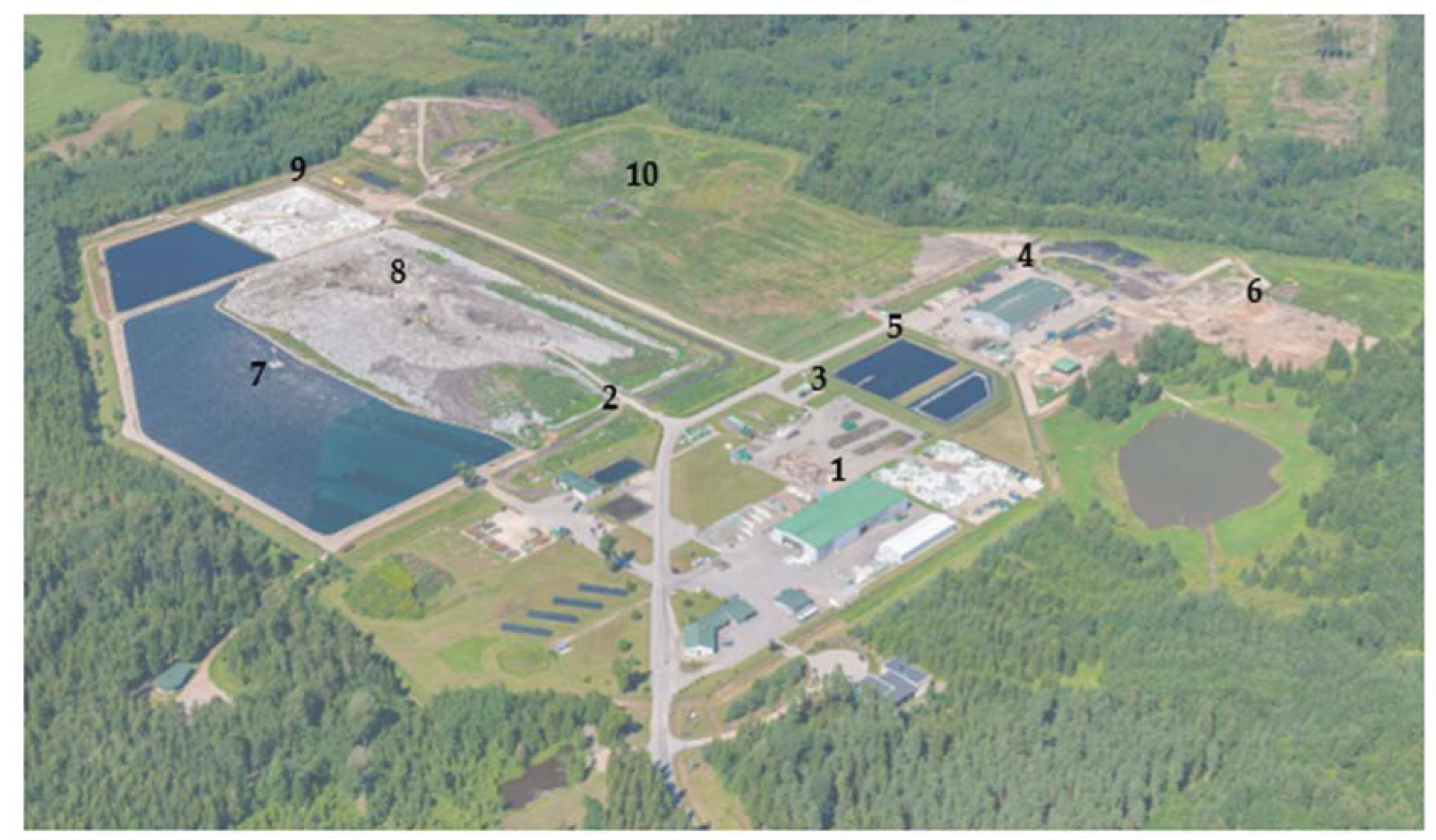
Latvia, like many other countries, is confronting these waste management issues. Although waste landfill sites, like the “Daibe” landfill near Cēsis, Latvia, operate according to legislative requirements, it is essential to pursue more sustainable and efficient waste management solutions [
6,
7]. While this study focuses on the “Daibe” landfill, the methods and findings have global relevance, highlighting universally applicable principles of waste management and renewable energy generation. Furthermore, waste does not respect national borders. Mismanaged waste can lead to environmental pollution that impacts neighboring countries and potentially the whole world. Plastic waste, for example, can enter the sea and spread globally, harming marine life everywhere. The need for efficient, sustainable waste management, and the potential of waste materials for renewable energy generation, are shared across geographical boundaries, emphasizing the global applicability of this study.
Waste-to-energy (WTE) technologies, such as gasification, have emerged as promising solutions, providing dual benefits of reducing waste volume and generating electricity and heat [
8,
9,
10]. Gasification transforms carbonaceous materials, including MSW, petroleum-based waste, sewage waste, and industrial waste, into syngas for heat and electricity generation, or as a raw material for producing chemicals and fuels, such as synthetic natural gas, hydrogen, synthetic diesel, gasoline, or methanol [
11,
12]. The utilization of waste-derived feedstocks, such as solid recovered fuel (SRF), which can be produced from non-hazardous MSW, enhances resource efficiency and promotes a circular economy by extracting energy and materials from waste [
13,
14]. Subsequently, extracting energy and materials from waste is a key component of a sustainable waste management strategy.
There are several types of gasifiers, each with unique operational characteristics, including fixed bed gasifiers, fluidized bed gasifiers, entrained flow gasifiers, and plasma gasifiers, which are designed to convert various types of feedstocks into usable forms of energy or chemicals. Each of these gasifiers has its own strengths and weaknesses, and the selection of the most appropriate gasification method depends on factors such as the type and properties of the feedstock, the desired product, the scale of operation, and the available resources. It is also important to manage these processes properly to mitigate any potential environmental and health impacts, such as emissions of GHGs or the creation of hazardous byproducts. Although circulating fluidized bed (CFB) gasification is identified as an efficient choice for MSW gasification, challenges persist, including managing abrasive and corrosive feedstocks and optimizing process parameters [
3,
15,
16,
17]. Moreover, literature lacks comprehensive studies on integrated systems, particularly those employing CFB gasification with MSW-derived SRF, and detailed environmental impact assessments [
16,
17,
18,
19,
20,
21,
22,
23]. Despite the noteworthy insights offered by the extant literature, there is a distinct deficiency of comprehensive studies examining integrated systems, specifically those employing CFB gasification with MSW-derived SRF. This gap is observed, even in the midst of several studies like those conducted by Fan et al. [
16], Yin et al. [
17], Behrend and Krishnamoorthy [
18], Begum et al. [
19], Chen et al. [
20], Kartal et al. [
21], Liszka et al. [
22], and Garcıa-Ibanez et al. [
23]. While these investigations contribute significantly to the body of knowledge on CFB gasification, the specifics of gasification involving MSW-derived SRF within an integrated system remain largely uncharted territory.
Addressing the research gaps, this study develops and analyses a comprehensive model of an integrated WTE system that transforms MSW into SRF, generates syngas through CFB gasification, and subsequently utilizes syngas for energy production. Specifically, the proposed model is based on waste data from the “Daibe” landfill (Latvia), providing a case study with potential global applicability. The specific objectives are to analyze the performance, energy efficiency, and environmental impact of the proposed WTE system and explore potential optimization opportunities.
The remainder of the paper is organized as follows:
Section 2 presents the methodology,
Section 3 discusses the results,
Section 4 provides a comprehensive discussion on the findings, and
Section 5 concludes and suggests potential avenues for future research.
3. Results
3.1. Waste Composition
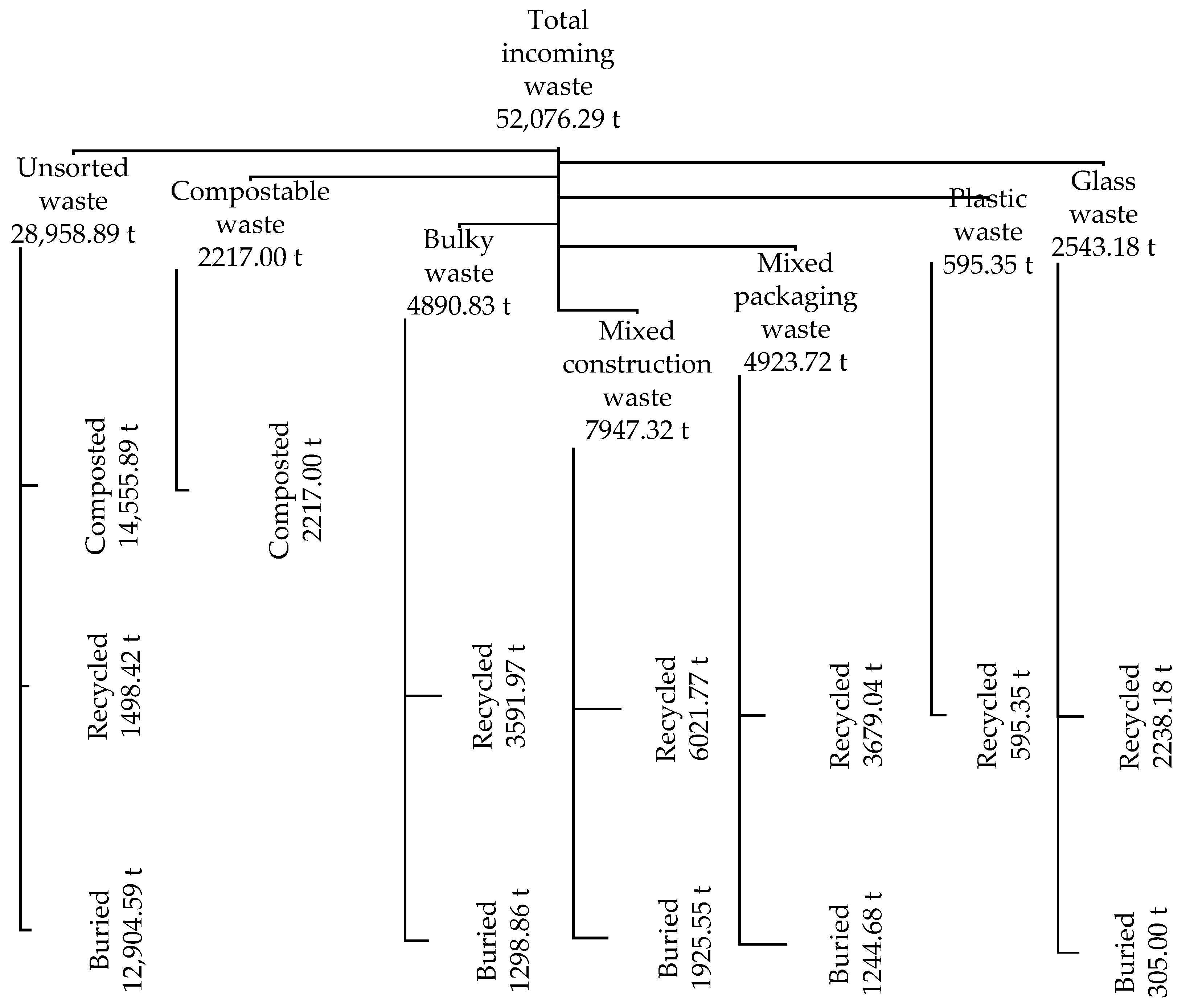
A comprehensive analysis of waste data from the “Daibe” landfill showed a management total of 52,076.29 t of waste in 2021 (
Figure 2). Even though the waste data used in the study are from 2021, they are still relevant to the study in 2023 because waste generation and composition tend not to change drastically over such a short period. Although there may be slight variations year to year due to changes in consumption patterns, policy, or waste management practices, the core composition of MSW tends to remain relatively constant. The data from 2021 can provide a reliable basis for understanding the typical characteristics of the waste that the WTE system will process. Moreover, these data can be used to optimize the system parameters for the most common types of waste, enhancing its efficiency and performance. Yet, future work should periodically update the waste data to ensure that the WTE system continues to be optimized for current conditions.
Unsorted waste constituted the majority (55.64%), followed by other substantial waste streams, including compostable waste, plastic waste, and glass waste. Every waste stream was processed upon arrival at the landfill to differentiate between recyclable, non-recyclable, and compostable waste. As the most significant incoming waste, the unsorted waste was distributed into compostable waste (50.3%), non-recyclable waste (44.6%), and recyclable waste (5.2%). Notably, the compostable and plastic waste streams were entirely directed towards composting and recycling, respectively. Additionally, bulky waste (73.4%) and mixed construction waste (75.8%) were largely recycled. The mixed packaging waste stream was also predominantly recycled (74.7%). Despite these practices, a significant proportion of incoming waste (32.2%) ended up in the landfill, indicating an area for improved waste management practices.
Table 1 presents the detailed breakdown of waste streams and their subsequent processing outcomes.
Table 1 provides an in-depth breakdown of the waste streams managed by the “Daibe” landfill in 2021, showing total incoming tonnage and the amounts recycled, composted, or buried. Unsorted waste was the predominant stream, with 28,958.89 t received, and a considerable fraction was composted or recycled. However, 44.6% of unsorted waste still ended up in the landfill. All incoming compostable, plastic, and glass waste was effectively processed for composting or recycling, respectively. However, significant portions of bulky waste, mixed construction waste, and mixed packaging waste were buried in the landfill, marking these waste streams as potential targets for optimized waste management strategies.
Given that compostable waste and plastic waste streams were entirely directed towards composting and recycling, respectively, and bulky waste, mixed construction waste, and mixed packaging waste were largely recycled, it seems likely that non-recyclable waste from the unsorted waste stream would form the majority of the input for the gasification process. This could be supplemented by portions of other waste streams that are not suitable for recycling or composting.
The conversion of waste to SRF carries significant potential for alleviating landfill burden [
10,
13,
14]. From the 14,149.27 t of unsorted and mixed packaging waste, approximately 11,319.416 t of SRF could be generated with an 80% conversion efficiency. This could reduce the amount of waste headed for landfill from 17,678.68 t to a more manageable 3529.41 t, showcasing a considerable improvement in waste management practices. The 80% conversion efficiency is an approximation, taking into consideration variables such as waste composition, technical constraints, and quality control requirements [
43,
44]. When compared to industry benchmarks, this percentage holds promise, especially considering that not all waste components can be converted into SRF due to inefficient combustion or potentially harmful emission issues (e.g., certain plastics release toxic gases).
The waste sample used for composition analysis was representative of the waste stream, including all types of waste appropriate for gasification in the proportions found within the total waste stream [
45]. The MSW sample was meticulously constructed to accurately represent the diverse waste stream, encompassing all waste categories apt for gasification, in proportions reflecting their prevalence within the aggregate waste stream. Specifically, the MSW sample comprised 91.25% unsorted waste, with the residual 8.75% comprising mixed packaging waste. When quantified on a mass basis, this composition suggests that each metric ton of the sample integrates 828 kg of unsorted waste and 172 kg of mixed packaging waste.
The transformation of MSW into SRF involved a multifaceted process, incorporating stages of drying, shredding, sorting, and pelletizing. Initially, the MSW was subjected to a desiccation procedure to decrease the moisture content to a target level of 25%. Post-drying, the moisture-reduced MSW was processed through shredding to achieve particles with a maximum dimension of 10 cm. This was followed by successive rounds of sorting to extricate unsuitable materials. The thoroughly sorted MSW was then subjected to a secondary shredding process, aimed at reducing the particle size further to 2.5 cm. The final stage of this sequence involved the transformation of these finely shredded materials into 5 cm pellets through a process known as pelletization, culminating in the production of SRF. The SRF sample produced from the non-recyclable and non-compostable MSW in this study exhibited promising characteristics: moisture content—25% (wet basis); volatile matter—65% (dry basis); fixed carbon—15% (dry basis); ash content—10% (dry basis); lower heating value (LHV)—15 MJ/kg (dry basis); and ultimate analysis (dry basis)—C (50%), H (6%), O (30%), N (1%), S (1%), Cl (0.5%), and others (11.5%). These characteristics were extrapolated to the entire waste stream of materials that can be gasified.
The SRF characteristics suggest an impressive fuel source. With a moisture content of 25%, the fuel is relatively dry, enhancing combustion efficiency [
46]. The volatile matter content of 65% and fixed carbon content of 15% indicate a well-processed SRF that burns quickly, efficiently, and for a prolonged period [
44,
47]. The LHV of 15 MJ/kg, in line with industry standards (10–20 MJ/kg), confirms the satisfactory energy potential for waste-derived fuels [
44,
48]. The ultimate analysis reveals that the SRF is primarily composed of the carbon, hydrogen, and oxygen typical in organic matter, with minimal amounts of potentially pollutant-contributing elements such as nitrogen, sulfur, and chlorine. These characteristics point towards a high-quality alternative fuel source that could be efficiently utilized in a WTE system. Yet, this potential needs to be explored in the context of broader environmental considerations and implications for the future of waste management practices [
49,
50,
51].
3.2. Model Operation Principle
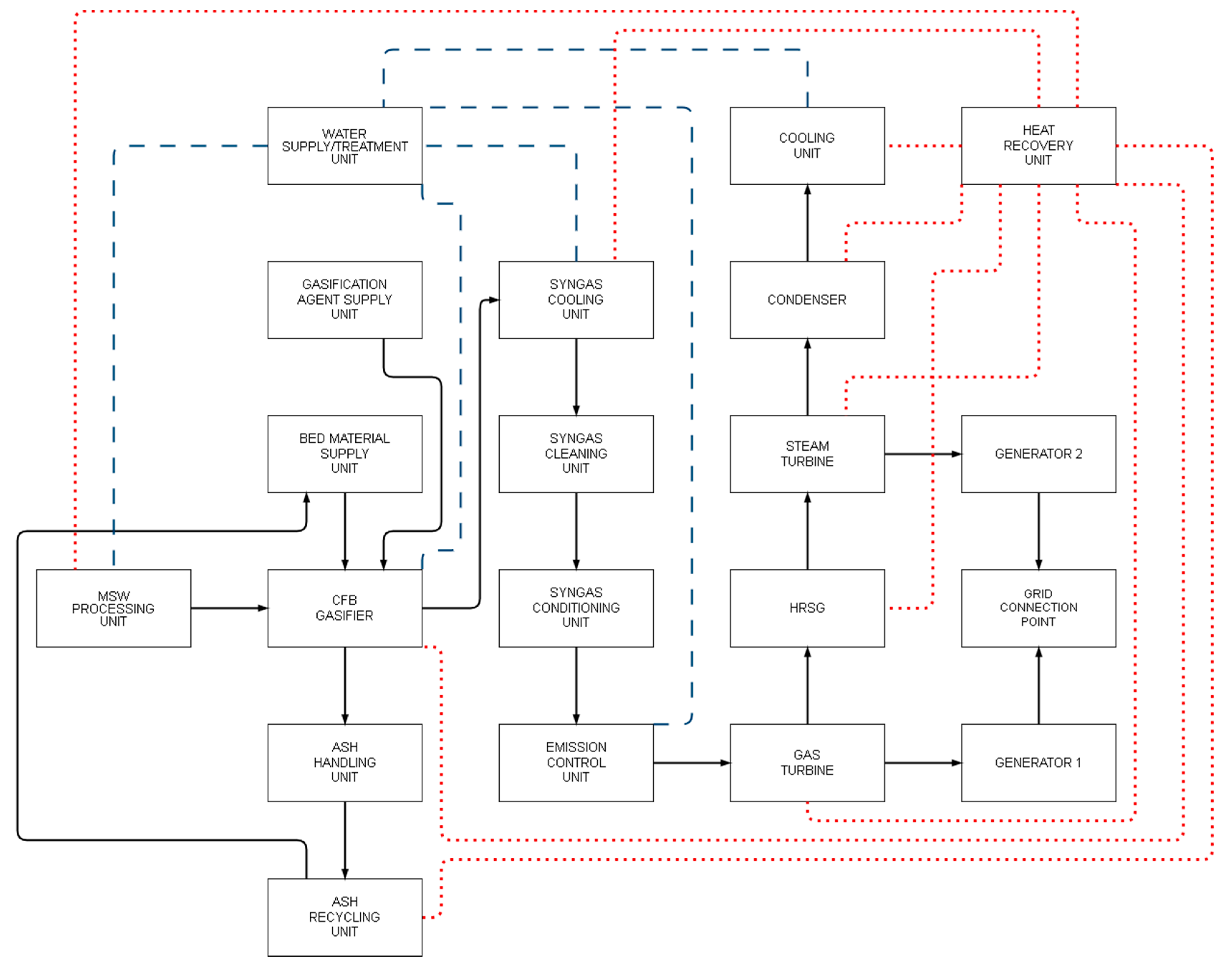
The model, as depicted in
Figure 3, comprises 20 interconnected units (via mass and energy flow), each signifying a distinct function in the system such as MSW processing, gasification, energy generation, and emission control.
The procedure commences with the MSW processing unit. Here, the incoming waste is sorted to separate recyclable, compostable, and non-recyclable materials. The unsorted and mixed packaging waste, targeted for SRF production, undergoes size reduction to simplify subsequent processing and handling. The water supply/treatment unit ensures the supply of water at the required flow rate, temperature, pressure, and purity essential for the operations of other components within the system. The sorted and size-reduced waste then undergoes further processing to produce SRF. This process includes drying, shredding, and pelletizing the waste material to create a uniform, high-energy fuel appropriate for gasification. The produced SRF is then fed into the CFB gasifier, a unit where thermochemical conversion occurs at high temperatures in a controlled oxygen environment. This conversion leads to the production of syngas, a combustible gas that holds potential for energy generation. In the ash handling and recycling units, the solid by-products of the gasification process are managed. Here, the ash is collected, processed, and either recycled or disposed of appropriately. The gasification agent supply unit delivers the required gasification agent (oxygen) to the CFB gasifier. The syngas cooling, cleaning, and conditioning units ensure the syngas produced is cooled, cleaned, and conditioned to the required quality for subsequent usage. This entails lowering the temperature of the syngas, removing impurities, and adjusting the syngas composition to satisfy the requirements of the downstream components. The cleaned and conditioned syngas then fuels a gas turbine to generate electricity. The exhaust heat from the gas turbine is harnessed by a heat recovery steam generator (HRSG) to produce steam, driving a steam turbine for supplementary electricity generation. The heat recovery unit further captures residual heat for other potential uses. The emission control unit ensures all emissions from the system meet applicable environmental regulations, thus mitigating the potential ecological impact. Finally, the grid connection point is where the generated electricity is delivered to the power grid. Here, parameters such as voltage, frequency, and power factor are controlled to align with grid requirements.
In summary, the proposed model aims to illustrate the efficient and sustainable conversion of waste into energy. The operational parameters of each unit are meticulously considered to optimize the overall performance of the system, aiming to achieve maximum efficiency at each stage. This model is expected to deliver substantial environmental benefits over traditional waste management and energy generation methods, given its comprehensive approach to emission control and residual heat recovery. The model’s ability to mitigate certain types of emissions, as well as its efficient use of waste heat, signifies its potential in advancing sustainable energy practices.
3.3. Simulation Results
The simulation of the WTE system provided essential insights into the optimal operational parameters for each component (
Table 2,
Table 3,
Table 4,
Table 5,
Table 6 and
Table 7). Unexpected results and outliers were minimal, indicating a consistent performance across the system under the simulated conditions.
Following the tabulated parameters (
Table 2,
Table 3,
Table 4,
Table 5,
Table 6 and
Table 7), the corresponding discussion below elaborates on these optimal values, illuminates their significance within the broader context of WTE system operations, and analyzes their impact on system performance, efficiency, and environmental implications.
The MSW processing unit demonstrated an optimal waste throughput of 10 t/day. With a moisture content of around 30% and a sorting efficiency of 80%, the unit managed to efficiently reduce the waste to a size of approximately 50 mm. This process indicates a significant level of efficiency and promises the production of a uniform and high-quality SRF, vital for optimal gasification. The water supply/treatment unit’s optimal conditions were achieved at a flow rate of 5 m3/h, a temperature of 20 °C, and a pressure of 2 bar. These optimized conditions assured efficient processing with minimal energy wastage, hence supporting the sustainability goals of the WTE system. The CFB gasifier’s performance peaked at a gasification temperature of 850 °C and a pressure of 1.5 bar. An oxygen-to-SRF ratio of 0.3 was optimal, with silica sand (200 μm) as the preferred bed material. These conditions facilitate effective gasification and enhanced the quality of the produced syngas, contributing to the overall system efficiency. The ash handling and recycling units exhibited optimal performance with a removal rate of 1 t/h and a moisture content of 20%, with high separation and recovery efficiencies. These parameters maximize the safe handling of ash and further reduce the environmental impact through the recovery and reuse of valuable materials. The gasification agent supply unit performed best with an oxygen purity of 95%, a flow rate of 5 m3/h, and a pressure of 5 bar. Meanwhile, the syngas cooling unit maintained the optimal performance with an inlet temperature of 850 °C, an outlet temperature of 250 °C, and a removal efficiency of 95% for the cleaning unit. These operational parameters ensure a high-quality syngas that meets the necessary requirements for downstream energy production. The gas turbine demonstrated optimal operation with an inlet temperature of 200 °C, a rotational speed of 3500 rpm, and an exhaust temperature of 550 °C. Together with the HRSG’s optimal parameters of a steam pressure of 50 bar and a temperature of 550 °C, these conditions assure efficient energy generation, contributing significantly to the WTE system’s overall efficiency. The generator’s electrical efficiency was optimal at 40%, with a voltage of 400 V and a frequency of 60 Hz. This high efficiency ensures effective energy conversion, which is a significant factor in the system’s overall performance. Similarly, the heat recovery unit displayed an optimal heat recovery efficiency of 90%, further enhancing the system’s energy efficiency.
Through this analysis, it becomes evident that the operational parameters of the individual components significantly influence the overall efficiency of the WTE system. The simulation results presented not only affirm the feasibility of the WTE system under study but also provide valuable insights into how to enhance its operation for maximal efficiency. It is expected that these findings will guide future designs and operational strategies for similar WTE systems, contributing to the broader objective of sustainable waste management and energy production.
Under ideal circumstances characterized by diligent maintenance routines, this power generation system has the potential to sustain operation at its rated parameters for protracted periods, even up to several years. However, this scenario presumes an environment free from operational anomalies and devoid of any progressive equipment degradation, which is, in most instances, an over-simplification. The actual operational schedule is complex and frequently necessitates adjustments to allow for sub-maximal operation. Such periods of reduced operation serve two critical functions: they accommodate the innate variability in energy demand and contribute significantly to preserving equipment longevity by minimizing wear and tear. Hence, the system does not perpetually operate at its rated parameters but adapts according to system requirements and broader resource conservation strategies. With respect to the proposed system, which operates on a smaller scale, a commensurate increase in the frequency of maintenance intervals is anticipated due to the relatively higher rate of wear and tear per unit of generated power. The length of continuous operation at rated parameters, therefore, becomes contingent on factors such as the steady supply of SRF and the thorough implementation of maintenance protocols. Given a continuous SRF supply and a rigorous adherence to operation and maintenance procedures, the system could feasibly operate uninterruptedly for durations extending up to several months. These estimations hinge inherently on the proficiency, expertise, and commitment of the operational and maintenance staff—factors that are paramount in determining the overall performance, efficiency, and lifespan of the system.
In conclusion, these simulation results align with the study’s objectives, demonstrating the potential of efficient WTE conversion. The operational parameters identified here are integral to optimizing system performance while ensuring environmental compliance, ultimately contributing to the broader goals of sustainability and efficient resource management.
3.4. Mass and Energy Flows
Both the mass and energy flows associated with the WTE system under investigation were closely examined. The mass flow involved the initial processing of MSW into SRF, followed by the transition of SRF into the gasification system. The intermediate flows included the transition of syngas from the gasifier to the gas turbine and the movement of ash from the gasifier to the ash handling and recycling units. The final outputs consisted of emissions from the gas turbine, ash residue from the gasification process, and any residual waste from the MSW processing stage.
Simultaneously, the energy flow throughout the system was observed and analyzed. The energy input came from the inherent energy content of the SRF, and the operational energy required to facilitate various processes, such as MSW processing, gasification, syngas cooling and cleaning, and ash handling and recycling. Energy transfers within the system were also examined, such as the transformation of SRF’s energy content into syngas in the gasifier, the subsequent conversion of syngas into mechanical energy in the gas turbine, and finally, the conversion of mechanical energy into electrical energy in the generator. The output of this energy flow was the electricity generated and subsequently supplied to the grid, the waste heat emitted from the gas turbine, and any potential energy losses that occurred within the system due to inherent inefficiencies.
The study showcases that these mass and energy flows are deeply intertwined, influencing the system’s efficiency and environmental impact. The mass of SRF fed into the gasifier, its composition, and the energy content had a direct effect on the amount of syngas produced, which, in turn, impacted the quantity of electricity generated.
A daily mass flow of 10 t of MSW was processed into SRF. The SRF then entered the gasification system. The gasifier, operating at a gasification temperature of 850 °C and an oxygen-to-SRF ratio of 0.3, transformed the SRF into syngas and ash. The syngas flow rate was determined based on the calorific value of the SRF (15 MJ/kg) and the specific operating conditions of the gasifier, contributing to the production of 2 MW of electrical power.
Regarding energy flow, the inherent energy content of the SRF, combined with the operational energy required for MSW processing and gasification, initiated the energy cycle. The energy contained in the SRF was transformed into syngas in the gasifier. This syngas, entering the gas turbine at an inlet temperature of 200 °C, was then converted into mechanical energy. The mechanical energy was finally converted into 2 MW of electrical energy in the generator, with an electrical efficiency of 40%.
The waste heat emitted from the gas turbine was captured and utilized within the system, particularly in the HRSG. The HRSG operated at a steam pressure of 50 bar and temperature of 550 °C, contributing to the system’s overall energy efficiency.
3.5. System Sensitivity and Efficiency
The proposed WTE system presents a remarkable overall energy efficiency of 70%, surpassing the average values for prevalent technologies, typically ranging between 20 and 35% for incineration plants and between 40 and 60% for advanced thermal treatments such as gasification and pyrolysis [
52,
53,
54,
55]. This high efficiency demonstrates the potential of our system in comparison to standard industry practices.
The estimated 70% efficiency of the proposed WTE system was derived from a comprehensive simulation that factored in a multitude of operational parameters. These parameters included the gasification temperature, pressure, oxygen-to-SRF ratio, and residence time, among others. This efficiency was further augmented by a suite of optimization strategies that were thoroughly implemented. These strategies encompassed feedstock preparation, meticulous temperature regulation, and efficient gas cleanup systems. At the same time, it is important to note that, in real-world applications, various other factors can also impact the efficiency of the proposed WTE system. These may include heat losses in various stages of the process, inefficiencies in energy conversion, operational variations, and the specific composition of the waste being used.
The system’s capacity for electricity generation is substantial, outputting 2 MW, a significant contribution that could meet a notable portion of local electricity demands, particularly beneficial for smaller communities or industrial settings [
56,
57].
Moreover, the system shows promising heat recovery potential of 1 MW. Such performance could efficiently support a district heating network or fulfill industrial process heat requirements, thus optimizing the utilization of the generated energy.
Regarding emissions, the system estimates CO
2 emissions of approximately 200 kg/h, a value that underscores the significant reduction in GHG emissions compared to conventional landfilling methods [
58]. Further emissions of concern in WTE technologies, such as NO
x (15 kg/h), SO
x (8 kg/h), and particulate matter (5 kg/h), are also maintained at relatively low levels, suggesting the incorporation of advanced and effective emission control technologies within the model [
59,
60].
Uncertainty analysis was carried out by executing multiple simulation scenarios with varied input parameters, examining their impact on system performance. The selected parameters—waste composition and moisture content, gasification temperature, and oxygen-to-SRF ratio—were chosen for their inherent variability in real-world scenarios and their known influence on the gasification process.
Variations in waste composition led to a ±5% deviation in energy output, owing to differing calorific values of MSW components. Alterations in the moisture content of the input material similarly affected the energy output. Drier inputs increased energy output, whereas wetter inputs decreased it. Adjusting gasification temperatures within a reasonable operational range (800–900 °C) resulted in a ±8% change in syngas yield, affirming that a balance between maximizing syngas yield and preventing operational issues like ash melting and slagging must be struck. In terms of oxygen-to-SRF ratio, a ±10% variation led to a ±6% change in overall energy efficiency, underlining the ratio’s crucial role in achieving maximum energy efficiency.
The sensitivity analysis delivered insights into the variables with the most pronounced impact on system outputs. The waste composition was found to have the greatest effect on energy output, with a sensitivity coefficient of 0.7. This means that a unit change in waste composition could lead to a 0.7-unit change in energy output. The gasification temperature followed closely, with a sensitivity coefficient of 0.6. The oxygen-to-SRF ratio had a slightly lower sensitivity, with a coefficient of 0.5. This indicates that even minor changes in these parameters could result in substantial impacts on the WTE system’s performance. Hence, the careful management and optimization of these variables would significantly enhance the system’s efficiency and output.
In conclusion, the system shows high energy efficiency and a promising level of power output compared to standard WTE technologies. The low levels of emissions align with an environmentally friendly approach. The robustness of the system against changes in key operational parameters was confirmed through uncertainty analysis, while sensitivity analysis highlighted the most impactful variables, providing a roadmap for future optimization efforts.
3.6. Emissions
The proposed WTE system is projected to generate approximately 200 kg of CO2 per hour of operation. At first glance, this figure may seem considerable. However, it is crucial to comprehend that the CO2 released during the energy extraction from MSW is part of the short-term carbon cycle. Unlike burning fossil fuels, which releases carbon stored for millions of years and contributes to an overall increase in atmospheric CO2, the carbon in MSW was recently in the atmosphere and is likely to be re-absorbed by plant growth in the near term.
Compared to other WTE technologies, such as incineration, which typically yields higher CO
2 emissions, the proposed system performs favorably [
61]. Furthermore, advanced thermal treatment technologies, like pyrolysis, may produce similar or slightly lower emissions depending on the specific system design and operational conditions.
An important comparison lies in contrasting the CO
2 emissions from the proposed WTE system with the potential emissions from the same waste if it were sent to a landfill. Notably, landfills produce significant amounts of CH
4, a GHG with a warming potential over 25 times greater than CO
2 over a 100-year period [
62,
63]. Thus, despite the CO
2 emissions from the proposed WTE system, it promises a net reduction in GHG emissions compared to the landfilling alternative.
The proposed system’s estimated emissions for NO
x (15 kg/h), SO
x (8 kg/h), and particulate matter (5 kg/h) are significantly lower relative to other WTE technologies. This favorable profile is mainly attributable to the advanced emission control technologies implemented in the proposed system, which may include scrubbers, filters, and catalytic reducers to capture and neutralize these pollutants [
64,
65,
66]. Thus, the system could potentially enhance local air quality and mitigate the health risks associated with these pollutants.
While the focus thus far has been on emissions during the energy generation phase, it is critical to take a holistic view and consider emissions throughout the entire lifecycle of the system. This includes everything from waste collection to the final disposal or recycling of residuals. While a comprehensive lifecycle assessment is outside the scope of the current study, the reduced emissions compared to landfilling, in conjunction with energy recovery, suggest a favorable lifecycle emission profile for the proposed system.
If we were to produce 2 MW of electricity from fossil fuels like coal or natural gas, the resulting GHG emissions would substantially exceed those from the proposed WTE system. With coal and natural gas power plants emitting, on average, around 820 and 450 kg CO
2/MWh, respectively, generating the equivalent amount of energy through these means would result in several times more CO
2 emissions [
67,
68,
69].
In summary, while the emissions from the proposed WTE system are not negligible, they represent a significant improvement over traditional waste disposal methods, such as landfilling, and over conventional fossil fuel power generation in terms of GHG emissions. The system offers considerable potential for contributing to climate change mitigation efforts and improving local air quality. However, it is essential to responsibly manage and control the system’s emissions as we continue refining the system to minimize emissions further and maximize energy recovery.
3.7. Economic Feasibility
Economic feasibility is a critical consideration in implementing WTE systems. At the same time, it is important to note that specific figures can vary widely based on numerous factors, including location, specific technology, local energy prices, regulatory environment, etc.
The establishment of a WTE system involves significant upfront investment. The costs can include system design, manufacturing, construction, installation, and initial operation. Based on typical global costs for WTE plants, it is not uncommon for initial capital costs to range between EUR 1500 to EUR 2500 per installed kW [
70,
71]. For a 2 MW system like the one simulated in this research, this translates to an estimated cost of EUR 3.5 M–EUR 5 M.
The operation and maintenance costs include labor, maintenance, repairs, and other routine operational expenses. The industry standards suggest these expenses typically constitute around 5–10% of the initial capital investment per year. Using the earlier range, this transforms to an estimated annual cost of EUR 150,000–EUR 500,000.
WTE facilities can reduce the need for landfill space. Considering the average cost to landfill waste can be anywhere from EUR 50 to EUR 100 per ton (EUR 66.79 for ZAOO Ltd.), this could equate to substantial savings. For a system processing 10 tons of waste per day (3650 tons per year), savings could range from EUR 150,000 to EUR 300,000 annually.
With the system generating 2 MW of electricity, the potential revenue will largely depend on the local energy prices. For instance, in many regions, prices can range from EUR 0.05 to EUR 0.20 and more per kWh [
72,
73,
74]. For a system operating continuously, this could equate to annual revenues ranging from EUR 750,000 to EUR 3,000,000.
In conclusion, while the upfront costs of establishing a WTE facility can be substantial, potential revenues from energy sales and landfill cost savings can contribute to a reasonable payback period. However, it is crucial to emphasize that these are estimated figures. The actual costs can differ based on various factors. Therefore, a detailed location-specific economic analysis would be necessary to determine the exact economic feasibility of the proposed WTE system.
3.8. Comparative Analysis
In the diverse landscape of WTE technologies, several approaches stand out, including incineration, anaerobic digestion, and various forms of gasification [
8,
9,
10,
11,
12,
13,
14,
15,
16,
17,
18,
19,
20,
51,
52,
53,
75]. The proposed integrated CFB gasification system is evaluated in the context of these methodologies, providing a clearer understanding of its performance and efficiency potential.
Incineration remains a prevalent WTE methodology, reducing the volume of MSW through combustion to generate heat, which can be converted into electricity. However, it frequently achieves lower energy efficiency compared to advanced thermal treatment technologies, such as gasification [
53], with typical efficiency ranging between 20 and 35%. In contrast to this, the simulated CFB gasification system secured an overall energy efficiency of 70%, indicating a noteworthy advancement over conventional incineration. Moreover, incineration can generate substantial emissions, necessitating extensive pollution control mechanisms. Coupled with the task of treating the bottom ash and fly ash produced during incineration, this underscores the relative environmental advantage offered by the CFB gasification system.
Anaerobic digestion provides an effective solution for processing organic waste through the decomposition of organic matter in an oxygen-free environment to produce biogas [
75]. Although it holds promise for biodegradable waste, it struggles with mixed MSW due to the requirement for meticulous pre-processing and segregation. Its energy efficiency varies widely based on waste composition and processing conditions. This contrasts with the more versatile CFB gasification system, which has demonstrated robust performance despite variations in waste composition, reinforcing its suitability for mixed MSW handling.
Other gasification technologies, including fixed bed, entrained flow, and plasma gasification, can achieve higher energy efficiency levels (40–60%) relative to incineration and anaerobic digestion [
76,
77]. Yet, the CFB gasification system showcased even higher efficiency at 70%. Furthermore, variations in operational parameters like waste throughput, moisture content, and gasification temperature enabled more effective optimization and control within the CFB system. Discussing these in the context of the technical complexity, operating conditions, feedstock requirements, and output characteristics of each method would further highlight the CFB system’s superiority.
In the context of this study, the term “efficiency” predominantly denotes the net energy conversion efficiency, specifically the fraction of energy embodied in SRF that is eventually transmuted into electricity or heat. This metric serves as a critical determinant in assessing the pragmatic ramifications of various WTE methodologies. It effectively quantifies the overall performance of a WTE process by measuring the proportion of retrievable energy from the SRF that can be harnessed and converted into practical forms, thus representing a crucial variable in the pursuit of optimizing energy recovery strategies.
A comprehensive comparison must consider not only operational performance and efficiency but also environmental and economic factors. Despite the proposed system’s estimated CO2 emissions, the reduction in GHG emissions relative to traditional waste disposal methods, such as landfilling and conventional fossil fuel energy generation, positions it as a more sustainable alternative. An evaluation of water usage, a critical factor in today’s climate-conscious world, and the cost-effectiveness of energy production would offer a well-rounded perspective of the system’s viability. Furthermore, the CFB gasification system’s robustness towards variations in waste composition underscores its potential as a promising WTE technology. This resilience is crucial in real-world scenarios where waste composition can vary significantly, an issue that could hamper the performance of other more sensitive systems.
In conclusion, the CFB gasification system exhibits notable advantages over traditional and other advanced WTE technologies. While the quest for optimizing emissions and energy recovery continues, this system offers a promising direction for future research and development in the field of WTE technologies.
4. Discussion
The findings from the research and the simulation results deliver compelling evidence for the potential of WTE conversion, especially regarding MSW. Notably, the study revealed that an optimal waste throughput of 10 t/day, a moisture content of 30%, a sorting efficiency of 80%, and a size reduction to 50 mm significantly enhance the waste management process. In line with findings from analogous studies, the utilization of a larger quantity of MSW necessitates a proportionately greater heat input, thereby escalating the overall operational cost of the system. Additionally, a higher moisture content in the MSW can significantly degrade the quality of the produced syngas [
3]. It should be noted that sorting efficiency is not a static metric and can exhibit considerable variance depending on the characteristics of the specific waste stream. This factor adds a layer of complexity to the system performance and must be managed accordingly. The influence of feedstock size, particularly in the case of SRF pellets, on the combustion process is also of significant importance. A reduction in particle size effectively increases the surface-area-to-mass ratio, thereby providing more area for the heat to penetrate, instigating the requisite chemical reactions, and consequently enhancing combustion efficiency. An optimally reduced particle size (such as 50 mm in our study) could potentially increase the yield of syngas due to the expanded surface area available for gasification reactions. However, this trend has an upper limit; exceedingly small particles may precipitate operational challenges such as defluidization or the excessive carryover of unreacted feedstock particles within the produced syngas. Therefore, careful optimization is required to identify the most suitable particle size, with our findings suggesting an optimal size of 50 mm based on referenced studies [
78,
79]. This underlines the crucial role that effective waste segregation and moisture control at the source level play in bolstering the efficiency of WTE conversion systems.
The CFB gasifier’s performance exhibited strong dependency on operational parameters such as gasification temperature, pressure, oxygen-to-SRF ratio, and residence time. The optimal conditions included a gasification temperature of 850 °C, pressure of 1.5 bar, an oxygen-to-SRF ratio of 0.3, and a residence time of 1.5 h. These findings align with previous research that demonstrates the significant role of the precise control of operational parameters in achieving improved syngas yields [
80,
81,
82]. The gasification temperature affects the rate and efficiency of the reactions in the gasifier. A temperature of 850 °C is often found to be suitable for achieving efficient gasification while avoiding unnecessary thermal stress on the system or excessive formation of slag or tar. For example, a study by Basu P. in his book,
Biomass Gasification, Pyrolysis and Torrefaction: Practical Design and Theory, [
83] highlights the impact of temperature on the overall process efficiency and syngas quality. Operating at slightly above atmospheric pressure (1.5 bar, in this case) can improve the reaction kinetics and increase the density of the syngas, improving the energy yield. The ratio of oxygen-to-SRF is crucial for controlling the gasification reactions. A ratio of 0.3 is within the range often reported for efficient gasification without excessive combustion [
84]. The residence time of the SRF in the gasifier affects how completely it can be converted into syngas. A time of 1.5 h allows for a near-complete conversion without unnecessarily slowing throughput [
85].
In terms of waste management, the high separation efficiency of 90% and a recovery rate of 80% in the ash recycling unit reduce landfill dependency and contribute to the recovery of valuable materials from the ash. This aspect, coupled with the system’s overall energy efficiency, positions the proposed CFB gasifier as a sustainable and economically viable solution for renewable energy generation.
The MATLAB simulation provided insights into the WTE system’s performance, demonstrating its potential to generate significant energy while minimizing environmental impacts. The sensitivity and uncertainty analyses revealed that, even with variability in input parameters, the system maintained its efficiency and sustainability, suggesting the robustness of this WTE system.
Despite the promising results, it is worth noting that the study is subject to certain limitations. For instance, the system’s performance could be compromised under certain extreme variations in waste streams and operational conditions [
86,
87]. Further research is needed to assess these edge cases and improve the system’s adaptability.
Waste composition had the most profound impact on energy output, reinforcing the need for efficient waste sorting and accurate waste characterization for optimizing WTE systems. As indicated by a sensitivity coefficient of 0.7, optimizing waste composition could significantly enhance the performance and efficiency of WTE systems.
The gasification temperature also showed a significant influence on the energy output, implying that meticulous control and optimization of the gasification temperature are vital to efficient energy recovery [
83]. However, the system showed relative flexibility to changes in the oxygen-to-SRF ratio, implying a degree of tolerance to slight variations in this parameter without substantial impact on energy output. The relative flexibility to changes in the oxygen-to-SRF ratio is also a phenomenon observed in other studies [
88].
The high energy efficiency of the system makes it a potentially economically viable solution for energy production from waste. The system’s efficiency contributes to a reduction in GHG emissions compared to landfilling and conventional fossil fuel power generation, suggesting a favorable environmental impact.
This research presents a comprehensive model of a WTE system with an overall energy efficiency of 70% under optimal conditions, which signifies a notable contribution to the field. For instance, the energy efficiency of a traditional incineration system is around 20–35%. On the other hand, a slightly higher energy efficiency of 40–60% can be achieved using various types of gasification methods [
52,
53,
54,
55]. Both these figures stand in contrast with the efficiency that has been achieved with the proposed CFB gasification system.
The energy recovery from MSW, as demonstrated by this research, further underscores its significance. According to a study by Safar et al., (2021), energy recovery from MSW can range widely based on the technology employed and waste composition, typically between 0.7 and 2.8 MWh/t [
89]. The proposed system’s ability to generate 2 MWh of electricity per ton of waste effectively positions it at the upper end of this range.
Concerning environmental impact, Consonni et al., (2005) highlighted that emissions from a WTE plant are heavily influenced by the choice of technology, with gasification systems generally presenting lower emission levels compared to incineration [
10]. This study aligns with this observation, indicating emissions of around 200 kg of CO
2 per hour of operation, which is within the acceptable limits for WTE technologies and significantly less than other conventional technologies such as landfilling and fossil fuel power generation [
10].
Waste composition’s impact on energy output has been widely discussed in the literature. For example, a study by Tchobanoglous et al., (1993) highlighted that a higher proportion of organic and high-energy content materials in waste composition leads to higher energy recovery [
90]. This observation resonates with the finding that waste composition had the most significant impact on the system’s energy output.
In light of the above, it can be concluded that this research contributes significantly to the existing body of knowledge in the field of WTE technologies. The high energy efficiency and low environmental impact demonstrated by the proposed system, particularly with its sensitivity to waste composition and gasification temperature, mark important steps forward in the pursuit of efficient and sustainable waste management solutions.
The WTE system proposed in this study, through the use of MATLAB simulation, has demonstrated promising efficiency and reduced environmental impact at a set scale. However, it is important to consider whether this system’s performance would remain consistent when scaled up. Given that the performance of the WTE system is heavily influenced by operational parameters such as waste composition and gasification temperature, it is reasonable to expect that large-scale operation might present additional challenges. These could include variability in waste composition over larger geographical areas, managing the gasification process at scale, and the handling and disposal of larger volumes of residual ash. However, on the positive side, the economies of scale might also play a role in making the system more viable. Larger operations could lead to more efficient energy production and a larger power output that might offset the costs of scaling up the operation. The higher energy efficiency of this system, compared to traditional WTE methods, may also provide a significant advantage in large-scale operations.
The translation of the simulated system into a real-world application entails several practical considerations. Infrastructure needs are one of the primary concerns. A full-scale implementation of this system would require space for the plant, appropriate waste storage and handling facilities, robust emission control systems, and a connection to the local power grid or an effective power storage system. The regulatory environment also poses a significant factor in real-world application. Each jurisdiction has different environmental and energy regulations that would affect the design, operation, and viability of the WTE plant. Furthermore, the logistical challenges of waste collection and transport, maintenance of the plant, and disposal or recycling of residual ash should not be overlooked. The presence of efficient waste segregation at the source would also be crucial in determining the system’s effectiveness. In addition to these practical considerations, public perception and acceptance of the WTE system is a crucial aspect of real-world implementation. Despite the environmental and energy benefits of WTE technologies, community concerns about emissions, waste handling, and the potential for increased waste generation can pose significant challenges to implementation.
5. Conclusions
This research offers an in-depth exploration of a WTE system, using a MSW feedstock, delivering invaluable insights into its performance, energy efficiency, and environmental impacts.
Utilizing a detailed simulation model, the study recognized the optimal operational parameters that enhance system efficiency and align with environmental regulations. These parameters span the waste processing unit, CFB gasifier, ash handling unit, gasification agent supply unit, syngas cooling unit, and emission control unit, among others.
The WTE system demonstrated a remarkable energy efficiency of 70% under these optimal conditions, positioning it as a high-performing alternative within WTE technologies. Sensitivity and uncertainty analyses further revealed the influential factors driving the system’s output and performance, with waste composition, gasification temperature, and the oxygen-to-SRF ratio emerging as key determinants. This underlines the critical role of effective waste segregation at the source and of the precise control of operational parameters in maximizing the system’s efficiency.
The results suggest that the proposed WTE system holds significant potential for advancing sustainable waste management and renewable energy generation. By directing waste away from landfills and converting it into a valuable alternative energy source, the WTE system integrates waste management with energy production, aligning it with sustainability goals.
Despite these promising results, the practical implementation of such a system requires the careful consideration of regional factors, including waste composition, climate, regulatory context, and socio-economic conditions. Furthermore, to truly assess the long-term sustainability of this WTE system, a comprehensive lifecycle assessment examining environmental impact and economic feasibility is needed.
In conclusion, this study lays a strong foundation for the further development of efficient WTE systems and underscores their potential in contributing to sustainable waste management and renewable energy production. Future research should continue to refine the simulation model, explore diverse waste streams and WTE technologies, and assess the broader social and environmental impacts of such systems.


