1. Introduction
Natural gas extracted from reservoirs does not have parameters that are required for fuel transported through the gas network and provided to end users. The gas produced requires the conditioning and adjustment of the pressure to the operating parameters of the transmission network. Required gas pressure values are determined in conditions for connection to the gas network (minimum, maximum, and nominal delivery pressure). The gas quality parameters, such as water and hydrocarbon dewpoint temperature, H
2S, CO
2, O
2 content, mercury vapor content, and cleanliness are specified in the PN-C-04752: 2011 standard [
1].
The types of gas contaminants, non-hydrocarbon components, and their concentrations vary between reservoirs and often also between neighboring wells. However, a common undesirable ballast is reservoir water. With increasing well production life, the water production increases simultaneously, what we call a water index increase. This is related to the undesirable water loading phenomenon, which also significantly decreases gas production.
The water presence in produced hydrocarbon mixture forces upstream companies to build water separation and dehydration plants. These modules are present in virtually all natural gas fields. The extracted water is divided into free water in the liquid state, which is relatively easy to remove in various types of separators, and water in the vapor state, which is separated in gas dehydration modules. Some verified gas dehydration processes are used in the Polish and world gas and oil industries. The most commonly used methods are [
2,
3,
4,
5,
6,
7,
8,
9]:
absorption with a few types of glycols and calcium and lithium chloride,
mole sieve, silica gel, or activated alumina adsorption,
valve expansion refrigeration–JT (Joule–Thomson) process.
In recent years new methods of gas dehydration have been developed, such as the following:
membrane units,
supersonic separators.
A particularly large amount of research work and industrial implementations are currently carried out in the field of supersonic separation, membrane, and adsorption units. The first two processes are suitable not only for dehydration but also for the separation of other components such as NGL (Natural Gas Liquids), CO
2, H
2S, or N
2 [
10,
11,
12,
13,
14,
15]. Adsorption units are particularly useful for deep gas dehydration, which is necessary for LNG (Liquefied Natural Gas) production and for NGL extraction from natural gas streams [
16,
17,
18].
The decision to build a gas dehydration plant should be obligatory and preceded by a technical and economic analysis based on the production forecast. Investors should consider factors such as the expected amount of produced gas, gas pressure decline, composition, pollution content, and dewpoint requirements.
Glycol, calcium, and lithium chloride dehydration plants are primarily used when gas is supplied to the transmission network and finally to end users. They all allow water dewpoints required in the transmission network to be achieved, but there is a crucial difference in CAPEX (Capital Expenditure) and OPEX (Operating Expenditure).
Units with calcium and lithium chloride pellets are used for the dehydration of small amounts of gas from several hundred to about one thousand Nm/h (in the two- or three-tower version). The capital costs of these installations are much lower than for glycol units. The price of such a module is significantly, or even several times, lower than the glycol plant, but the operating costs are much higher. This is due to the high cost of the pellets.
However, they have found wide application in the domestic gas and oil industry due to the possibility of working in many small and remote gas fields. They are manufactured in a skid-container-mounted construction that allows easy transport to a new location and allows for gas dehydration even from single wells with a small production rate. More expensive pellets with stronger hygroscopic properties could deal with low-pressure gas dehydration, which could not be processed successfully in conventional glycol systems.
The construction costs of the glycol units are much higher. Still, the operating costs (unit gas dehydration cost Nm) are significantly lower than for plants that work with calcium and lithium chlorides.
Glycol units are usually built as part of larger process plants and serve at least a few gas wells. In domestic conditions, plants are usually built for a capacity of several to tens of thousands of normal cubic meters of gas per hour, while abroad, in areas much richer in gas resources, units with a capacity of up to several hundred thousand normal cubic meters of gas per hour are constructed. Maintaining the gas pressure sufficiently high is crucial for properly operating the glycol dehydration unit. When the gas pressure drops below the value of approximately 25–30 barg, difficulties will appear with respect to meeting the water dewpoint specification requirements [
2,
7,
19,
20,
21,
22,
23,
24].
The producer could deal with this problem in a few ways:
Abandon exploitation of the lowest-pressure gas wells.
Installation of the compressor unit upstream to the dehydration plant.
Find methods of increasing the efficiency of the gas dehydration unit.
The loss of profits associated with the first solution makes it undesirable. The second option requires significant capital investment and must be planned in advance. Significant time is required to obtain the necessary legal permits, purchase equipment, and execute construction works.
Taking into account the current conditions, the simplest and most economically effective solution is to increase the dehydration efficiency of the existing plant. It could be achieved by increasing the glycol concentration in the regenerator to a value greater than 98.4 wt% for TEG and greater than 99.2 wt% for TREG [
5,
7,
25,
26,
27].
Virtually all known methods for increasing the concentration of L-TEG/L-TREG involve lowering the partial pressure of the glycol solution in the regenerator. If the pressure is reduced below 1 atm, we will obtain a lower water concentration in the regenerated L-TEG/L-TREG.
The following industrial methods can achieve this:
A stripping gas system where a small amount of gas is introduced directly into the reboiler or a packed “stripping column” between the reboiler and the surge tank. It takes advantage of Dalton’s law, which says that the total pressure of a mixture of gases is equal to the sum of the partial pressures of the individual component gases [
2,
3,
28].
The GLYNOXX, DRIGAS™, and ECOTEG™ processes with a closed stripping gas loop. Fuel gas or hydrocarbons from degassing TEG/TREG are used as a source of stripping gas [
29,
30,
31].
The DRIZO process with a close stripping gas lope and uses a material such as iso-octane or a mixture of aromatic, naphthenic, and paraffin hydrocarbons in the range C
5–C
10. They vaporize at reboiler temperature but can be condensed and separated from the water in a three-phase separator. The stripping solvent is then pumped back to the regenerator to complete the stripping loop [
3,
5].
The COLDFINGER process achieves glycol enrichment by passing a cooling medium (often the rich glycol) through a cool “finger” inserted in the vapor space of the surge tank. This condenses a water-TEG/TREG mixture that is rich in water. The mixture is drawn out of the surge tank through a trough below the ’cold finger’ and is recycled back to the regenerator [
32,
33].
An ejector or vacuum pump can be used to produce the necessary vacuum in the regenerator [
3,
34,
35].
Glycol concentrations in excess of 99.99 wt% have been achieved with the first four processes, but their implementation should be planned at the design stage. Their implementation in a working plant is a more difficult task and requires significant reconstruction and revisions in the classification of explosion hazard zones. It also contributes to increased greenhouse gas emissions if hydrocarbons are used as stripping gases.
Less awkward in this respect is the last method of creating a vacuum in the regenerator. The use of a gas ejector for this purpose seems to be particularly interesting. Despite their relatively low efficiency, ejectors are very simple in construction and resistant to challenging operating conditions, in contrast to vacuum pumps.
It is possible to make such a modification without interfering with the structure of the regenerator and other TEG/TREG regeneration unit elements. The ejector can be connected to the steam vent line from the still column to the separator and further to the atmosphere. It only requires the replacement of a short fragment of the low-pressure pipeline, and the ejector itself is treated as an element of the piping system. The modification will usually not require obtaining administrative approvals and permits or changing the registration documentation of tanks and pipelines subject to the PED (Pressure Equipment Directive). Proper organization and earlier preparation of the necessary materials allow construction work to be performed in several hours.
Compressed air can be used as a motive gas for the ejector. Air compressor units exist in most domestic gas processing plants and provide an energy source for industrial automation devices, such as shut-off or control valves in the dehydration unit. Often, the compressed air pipeline is already connected to the dehydration unit, and the ejector only needs to be connected with a short section of a new pipeline or flexible pipes.
The ejector allows for the increase in the efficiency of the glycol dehydration plant in a simple and relatively inexpensive way. Higher concentrations of regenerated L-TEG/L-TREG and, thus, lower water dewpoint temperature of gas could be achieved due to the created vacuum.
This paper presents new, very prospective technology for increasing the efficiency of absorption gas dehydration units. The technology could be characterized by simplicity, small weight and size of the final installation, relatively small energy consumption in the range of applicability, and as a result, low capital and operating expenses. The proposed installation is very simple and consists of an ejector and short sections of additional pipelines, which makes it very robust and inexpensive. An increase in the efficiency of the dehydration unit allows for extending the limits of absorption technology’s applicability.
2. Materials and Methods
Three process flow diagrams were prepared in the CHEMCAD process simulator, and a series of calculations were performed. The influence of vacuum, created by the gas ejector, on the regeneration of TEG/TREG was verified that way [
36,
37,
38,
39,
40].
The impact of pressure reduction on the lean TEG/TREG mass concentration and the obtained water dewpoint temperature of the gas were examined in the first simulation. The process flow diagram of the TEG dehydration plant was prepared. The TEG model was adopted to calculate the K-values equilibrium constants and the SRK (Soave–Redlich–Kwon) model for enthalpy calculations [
41]. The PSRK (Predictive Soave–Redlich–Kwon) model to calculate K-values equilibrium constants and the Latent Heat model to calculate the enthalpy were adopted for the TREG dehydration plant. PSRK is a combined EoS (Equations-of-State) and activity coefficient method in which SRK is used for the vapor and UNIFAC (Universal Functional Activity Coefficient) for the liquid and has special subgroups for the light gases. This concept makes use of recent developments and has the main advantage that VLE (Vapour–Liquid Equilibrium) can be predicted for a larger number of systems without introducing new model parameters that must be fitted to experimental VLE data. The PSRK equation of state can be used for VLE predictions over a much larger temperature and pressure range than the UNIFAC approach and is easily extended to mixtures containing supercritical compounds. Additional PSRK parameters, including light gases, allow the calculation of gas–gas and gas–alkane phase equilibrium. It was also assumed in the thermodynamic properties of the models that water and hydrocarbons do not mix [
36].
Gas dehydration simulations were performed for four values of gas working pressure 30, 26, 20, and 15 barg and TEG/TREG regeneration pressures in the range of −0.5–+0.07 barg.
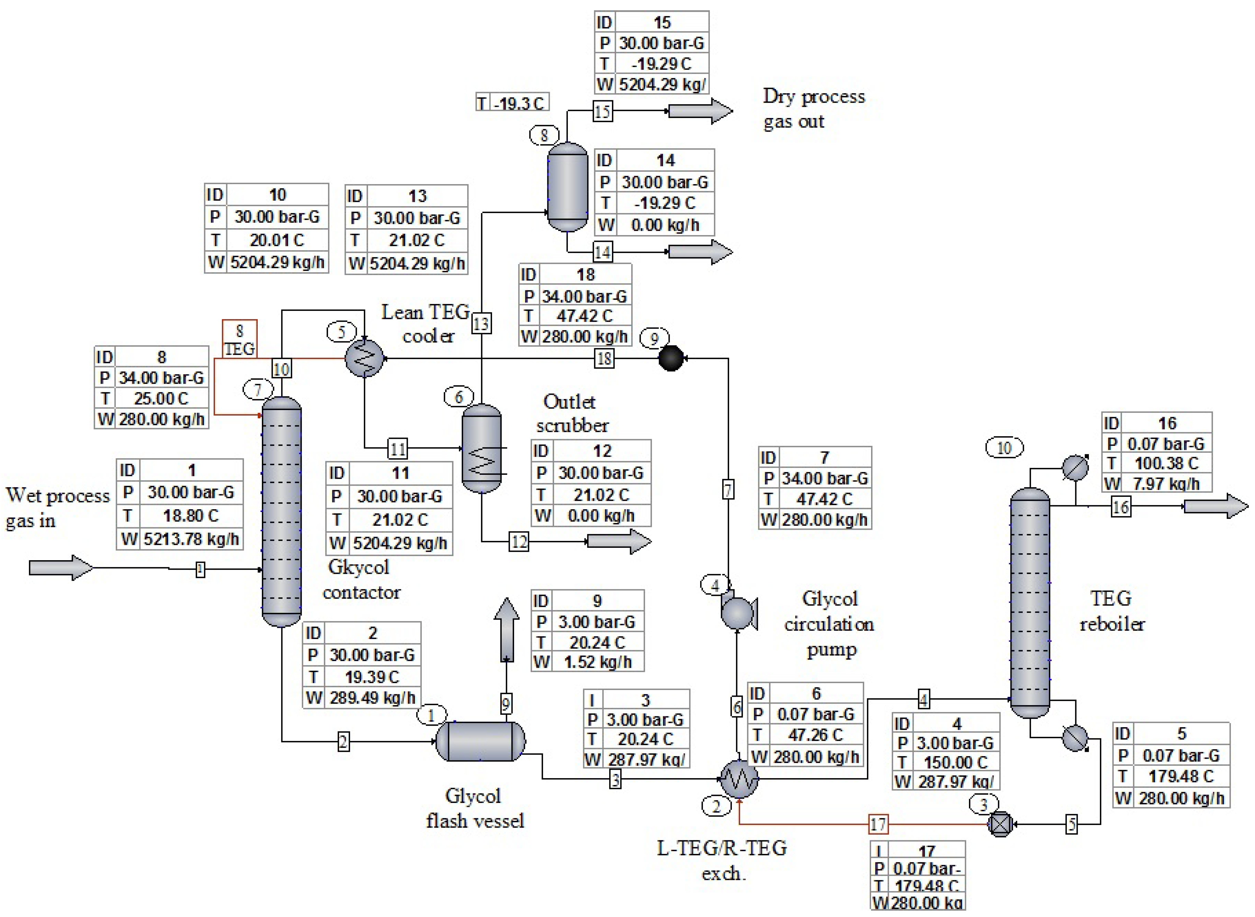
Figure 1 presents the process flow diagram for the tested variants. The influence of the L-TEG/L-TREG flow rate on the obtained water dewpoint temperatures was also checked [
42].
The glycol reboiler maintains the TEG bath temperature at about 180 °C, which is 26 °C lower than the thermal decomposition temperature of TEG (206 °C). For TREG, the bath temperature was assumed to be 213 °C, which is 25 °C lower than the thermal decomposition temperature of TREG (238 °C) [
43,
44,
45].
The simulations were performed for the following technical parameters of the glycol contactor and regenerator [
46,
47,
48,
49,
50,
51]:
Glycol contactor
Diameter DN600 (610 × 12.5 mm).
The packing height is about 3 m.
Packing type—random packing, Białecki rings [
52].
A minimum required L-TEG concentration 98 wt%.
A minimum required L-TREG concentration 99 wt%.
Absorber design pressure (PS) 40 barg.
TEG regenerator
Still column diameter DN150 (168.3 × 8.0 mm).
Upper section packing height is about 1.47 m.
Lower section packing height is about 0.44 m.
Reboiler vessel diameter DN900 (914 × 10 mm).
The gas burner power is about 15–55 kW.
A minimum required L-TEG concentration 98 wt%.
A minimum required L-TREG concentration 99 wt%.
Natural gas was assumed to be composed of 99% methane.
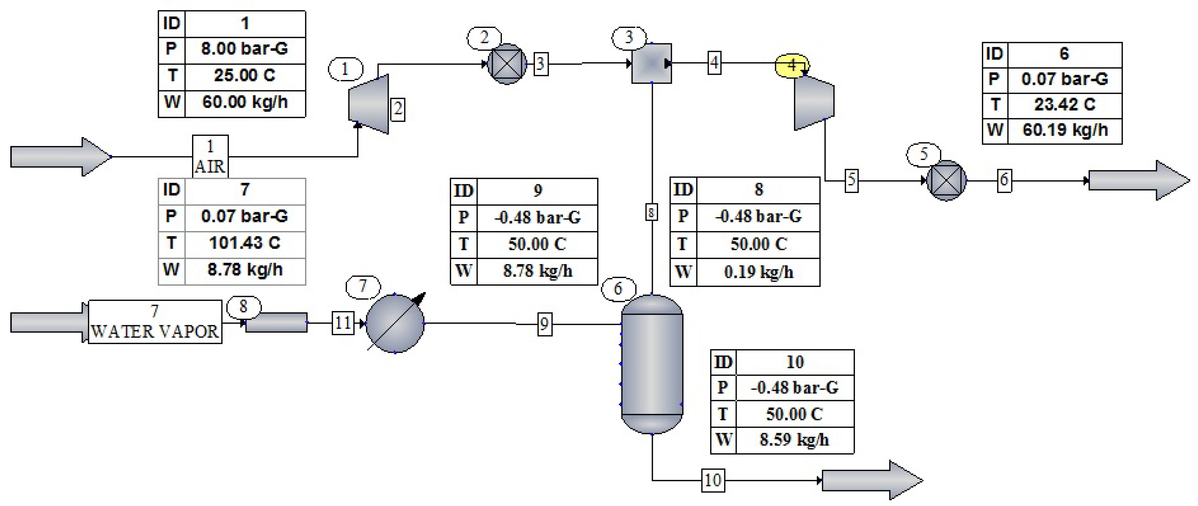
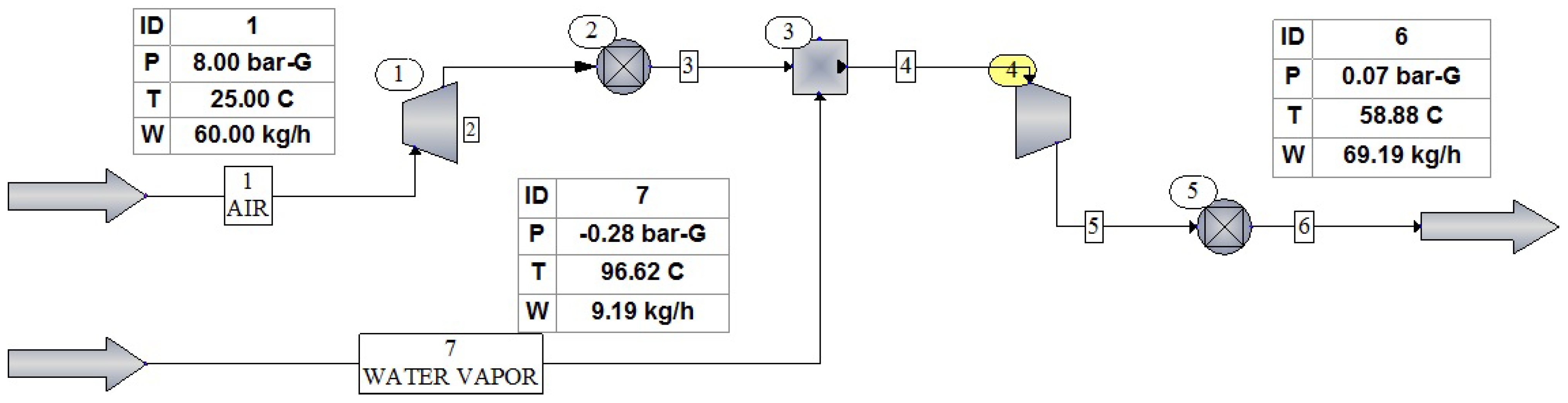
The two following process simulations estimated the quantity of compressed air required to create a vacuum in the regenerator. CHEMCAD software does not have an ejector unit operation; therefore, its performance was modeled by an adiabatic system of the expander and a gas compressor. The power consumption of the compressor is equal to the expander power production with the opposite sign, so the whole system does not do any work. An upper value of the ejector efficiency of approx. 30% was assumed for the simulation [
53,
54]. The flow diagrams of the ejector process are presented in
Figure 2 and
Figure 3.
A pressure value of 8 barg was assumed for the HP (High Pressure) air stream, which is a typical value for air compressors used in gas processing plants. The air temperature was assumed to be +25 °C. The LP (Low Pressure) stream consists of water vapor and hydrocarbons separated from glycol in the regenerator at a reflux temperature of approximately +100 °C. The LP flow rate is 6.74 kg/h, 7.63 kg/h, and 9.2 kg/h for TEG and 6.31 kg/h, 7.34 kg/h and 8.78 kg/h for TREG, respectively. These vapor streams correspond to the amount of water and hydrocarbons separated during TEG/TREG regeneration. At the same time, the working pressure of the dehydrated gas is equal to 26 barg, 20 barg, and 15 barg, respectively.
Ejector performance simulations were executed for two positions in the process flow diagram. In the first variant, the ejector was situated downstream of the condensed water separator. Hydrocarbons degassing from the TEG/TREG were mainstream components in this case. In the second variant, the ejector was placed downstream to the still column and upstream to the air cooler. The LP stream is a mixture of water vapor and hydrocarbons, significantly greater than previously.
For the second case, the outlet pressure of the gas mixture was set to 0.07 barg. This value is slightly greater than pressure losses in pipelines and equipment between the ejector and the gas outlet to the atmosphere (liquid separator, gas cooler, pipeline, etc.).
The outlet pressure of the ejector could be reduced to a value very close to atmospheric pressure when the ejector is installed on the outlet pipeline downstream to the condensed water separator. In this case, the exhaust gas stream from the ejector is discharged directly to the atmosphere.
3. Results
TEG dehydration plant simulation results and required water dewpoints temperatures according to PN-C-04752: 2011 are presented in
Table 1. The values were obtained for the base variant, in which the gas working pressure is 30 barg and for decreasing gas working pressure up to 26 barg, 20 barg, and 15 barg.
Additional simulation results for the increase in L-TEG circulation rate to 450 kg/h (which corresponds to the maximum capacity of the circulation pump) are presented in
Table 2.
TREG dehydration plant simulation results and required water dewpoints temperatures according to PN-C-04752: 2011 are presented in
Table 3. The values were obtained for the base variant, in which the gas working pressure is 30 barg and for decreasing gas working pressure up to 26 barg, 20 barg, and 15 barg.
Additional simulation results for the increase in L-TREG circulation rate to 450 kg/h (which corresponds to the maximum capacity of the circulation pump) are presented in
Table 4.
It should be stressed that the equilibrium water dewpoint temperatures obtained from the simulation could be achieved in a test cell but not in a real absorber. This is because the gas and TEG/TREG are not in contact for a long enough time to reach equilibrium. In addition, the gas theoretically leaves the top tray of the absorber in equilibrium, with the TEG/TREG leaving the tray and not entering. As reported by Campbell, numerous tests show that a well-designed, properly operated unit will have an actual water dewpoint 5–10 °C higher than the equilibrium dewpoint [
3,
41]. The value of this approximation assumed for our plant is 8 °C.
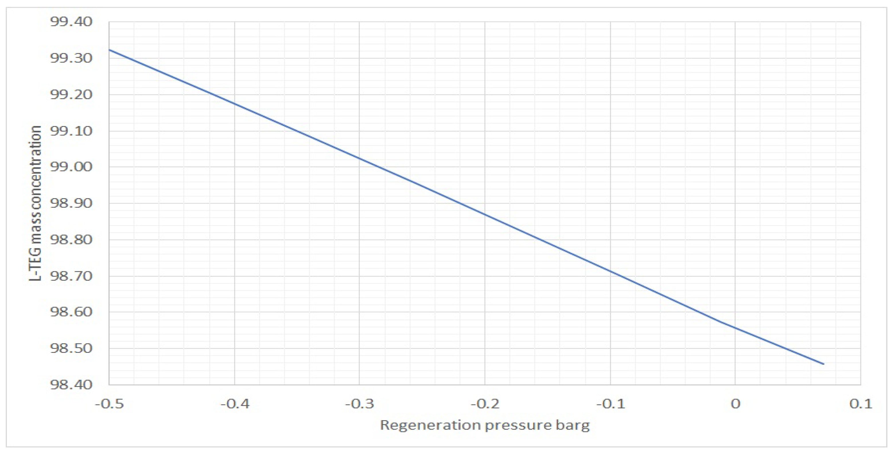
The influence of reboiler pressure reduction on achievable L-TEG concentrations and water dewpoint temperatures is presented in
Table 5.
The influence of reboiler pressure reduction on achievable L-TREG concentrations and water dewpoint temperatures is presented in
Table 6.
The results of the sensitivity analysis are shown in
Figure 4,
Figure 5,
Figure 6,
Figure 7,
Figure 8,
Figure 9,
Figure 10,
Figure 11,
Figure 12,
Figure 13,
Figure 14 and
Figure 15.
The obtained TEG regeneration pressures versus the 8-barg ejector motive air flow rates are presented in
Table 7. The amount of water vapor separated from the 280 kg/h TEG circulation stream for the three dehydrated gas pressure values were 26 barg, 20 barg, and 15 barg in the simulations. The ejector was placed downstream to the condensed water separator.
Obtained TREG regeneration pressures vs. 8-barg ejector motive air flowrates are presented in
Table 8. The amount of water vapor separated from the 280 kg/h TREG circulation stream for the three dehydrated gas pressure values were 26 barg, 20 barg, and 15 barg in the simulations. The ejector was placed downstream to the condensed water separator.
Obtained TEG regeneration pressures vs. 8-barg ejector motive air flowrates are presented in
Table 9. The amount of water vapor separated from the 280 kg/h TEG circulation stream for the three dehydrated gas pressure values was 26 barg, 20 barg, and 15 barg in the simulations. The ejector was placed downstream to the still column and upstream to the air cooler and water separator.
Obtained TREG regeneration pressures vs. 8-barg ejector motive air flow rates are presented in
Table 10. The amount of water vapor separated from the 280 kg/h TREG circulation stream for the three dehydrated gas pressure values was 26 barg, 20 barg, and 15 barg in the simulations. The ejector was placed downstream to the still column and upstream to the air cooler and water separator.
4. Discussion
The simulation results clearly indicate that the glycol dehydration unit with TEG atmospheric pressure regeneration will work properly until the gas pressure drops below 30 barg, as shown in
Table 1 and
Table 2. The results presented in
Figure 4,
Figure 6 and
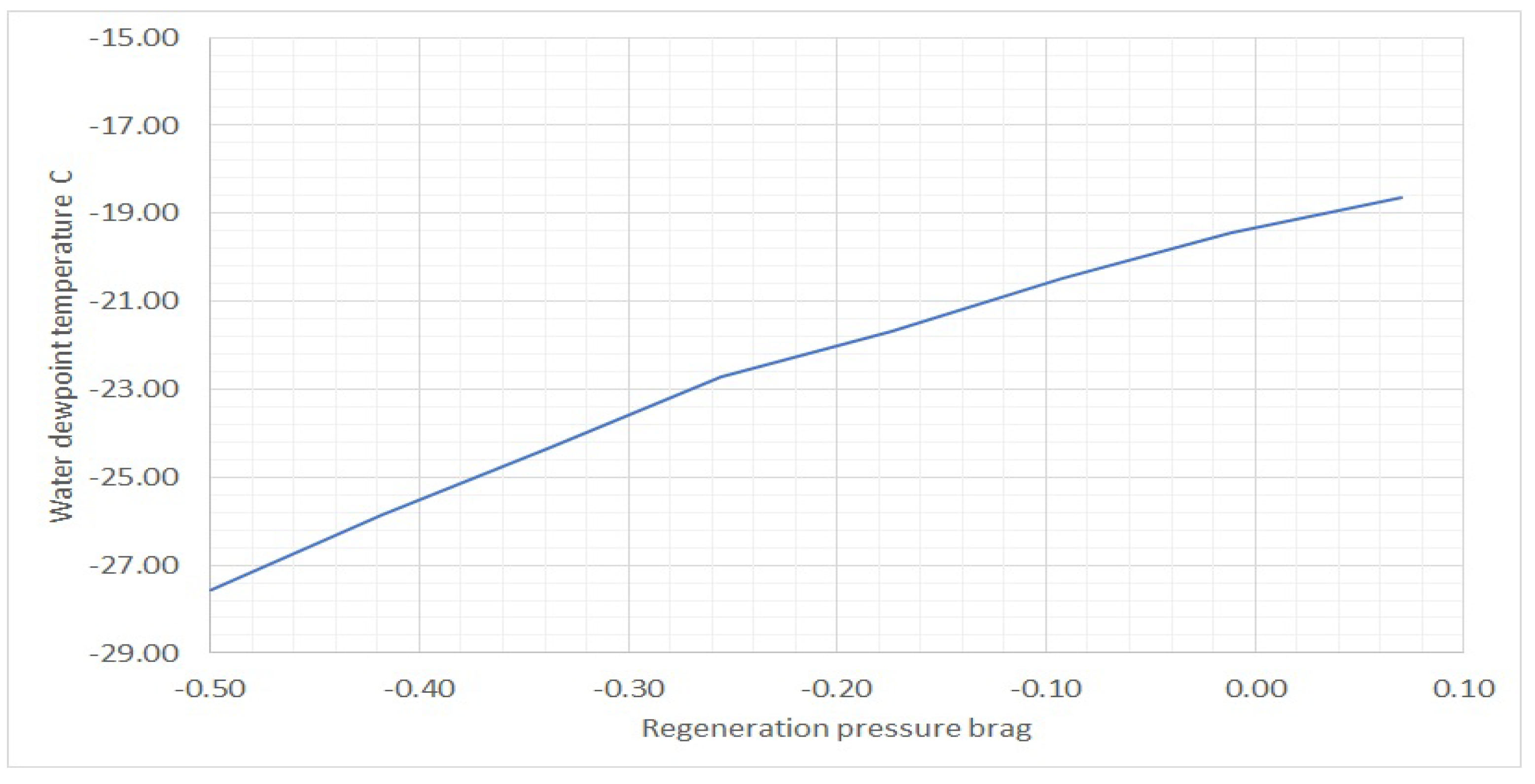
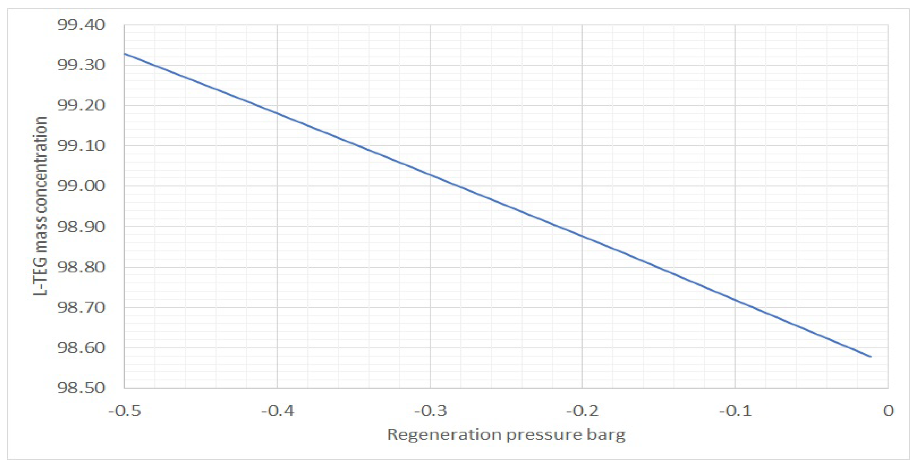
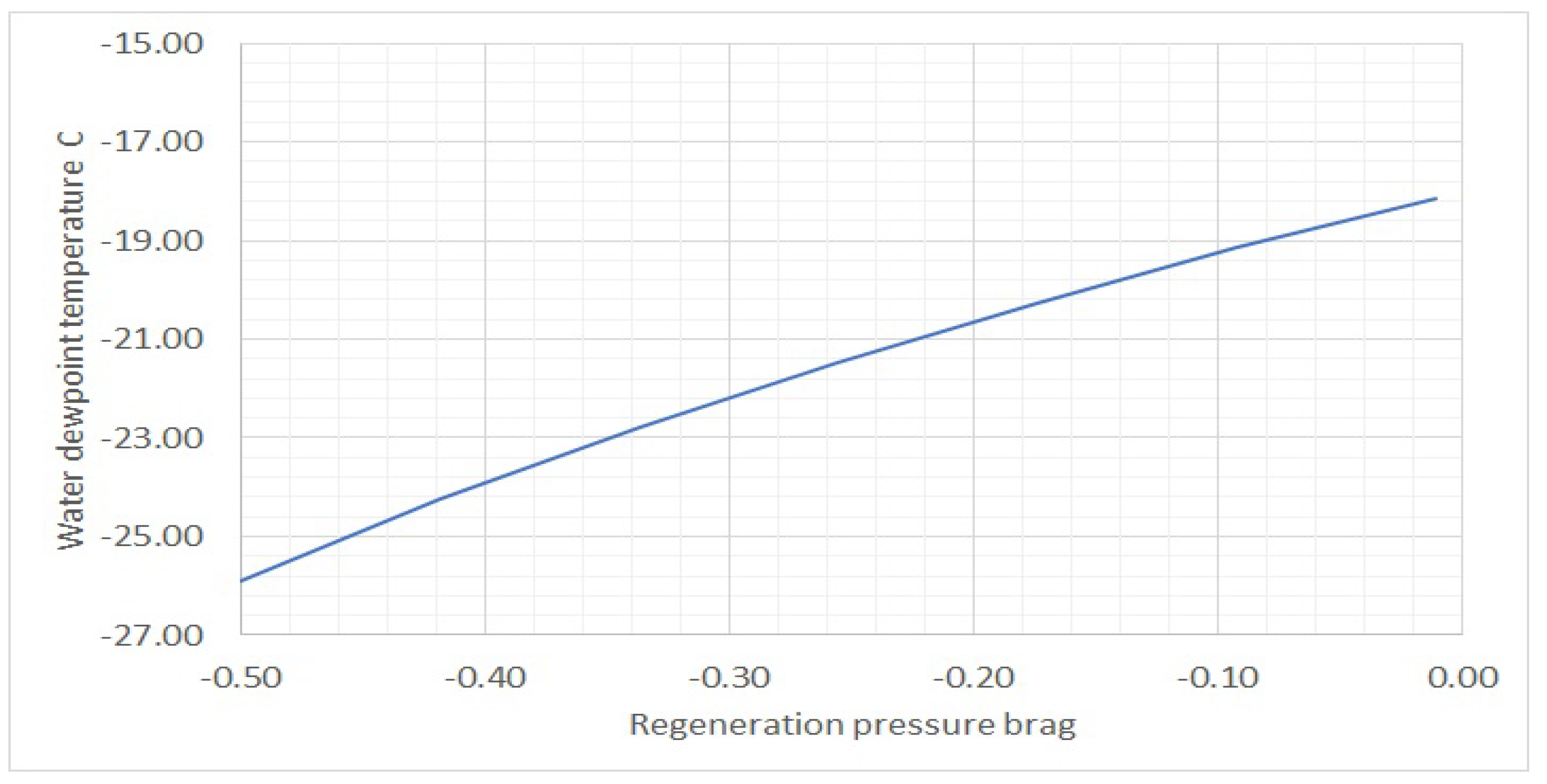
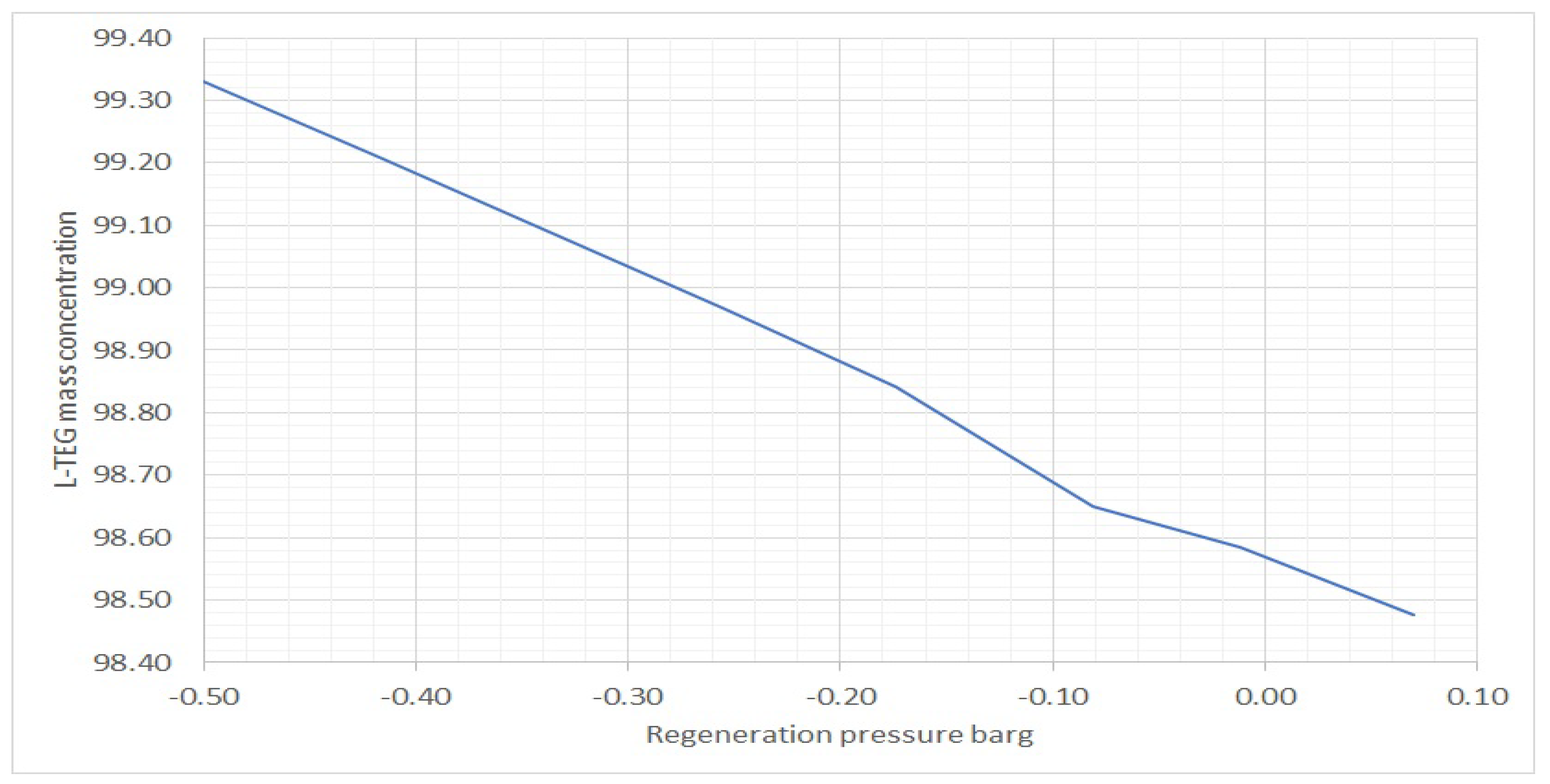
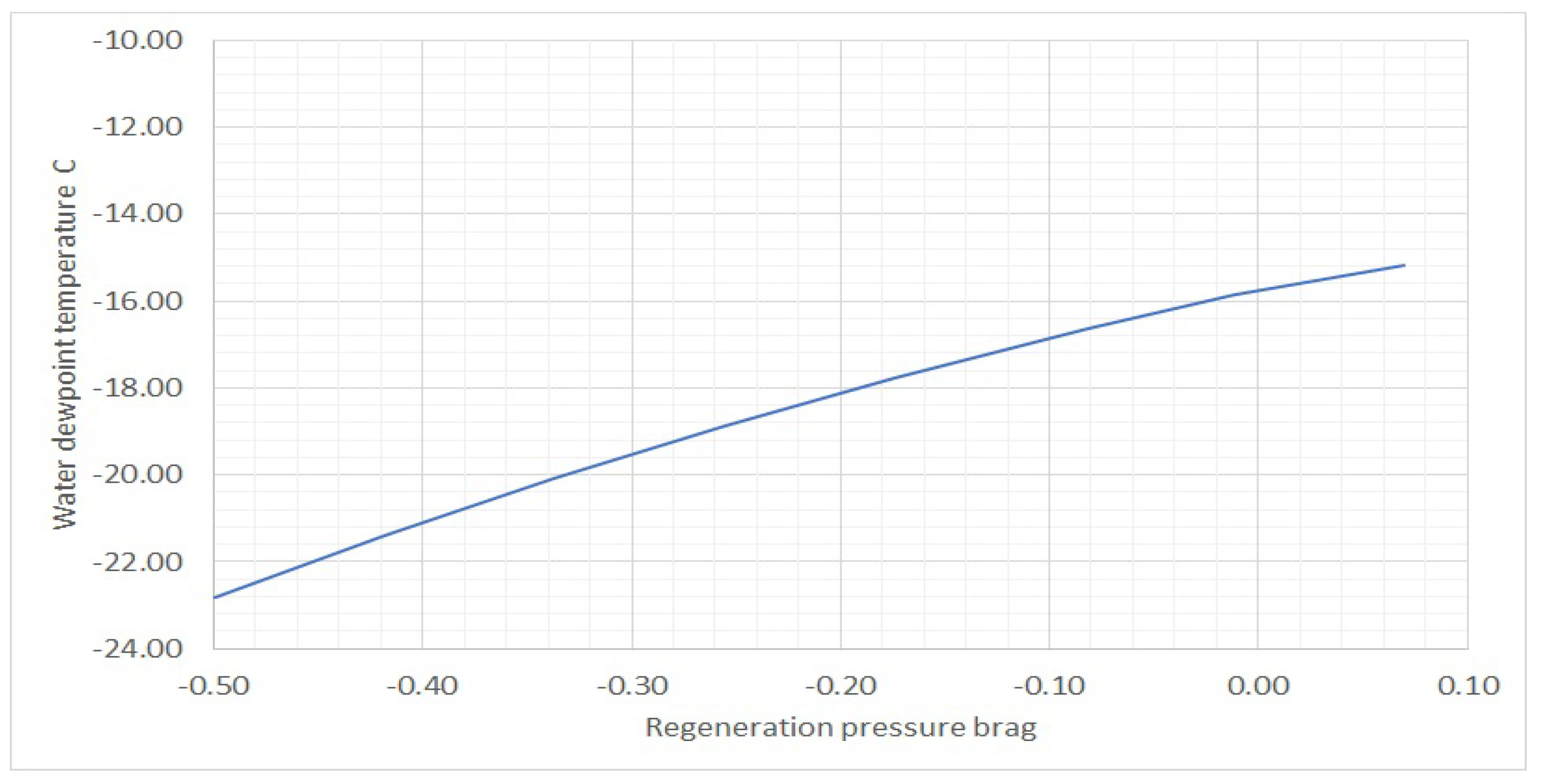
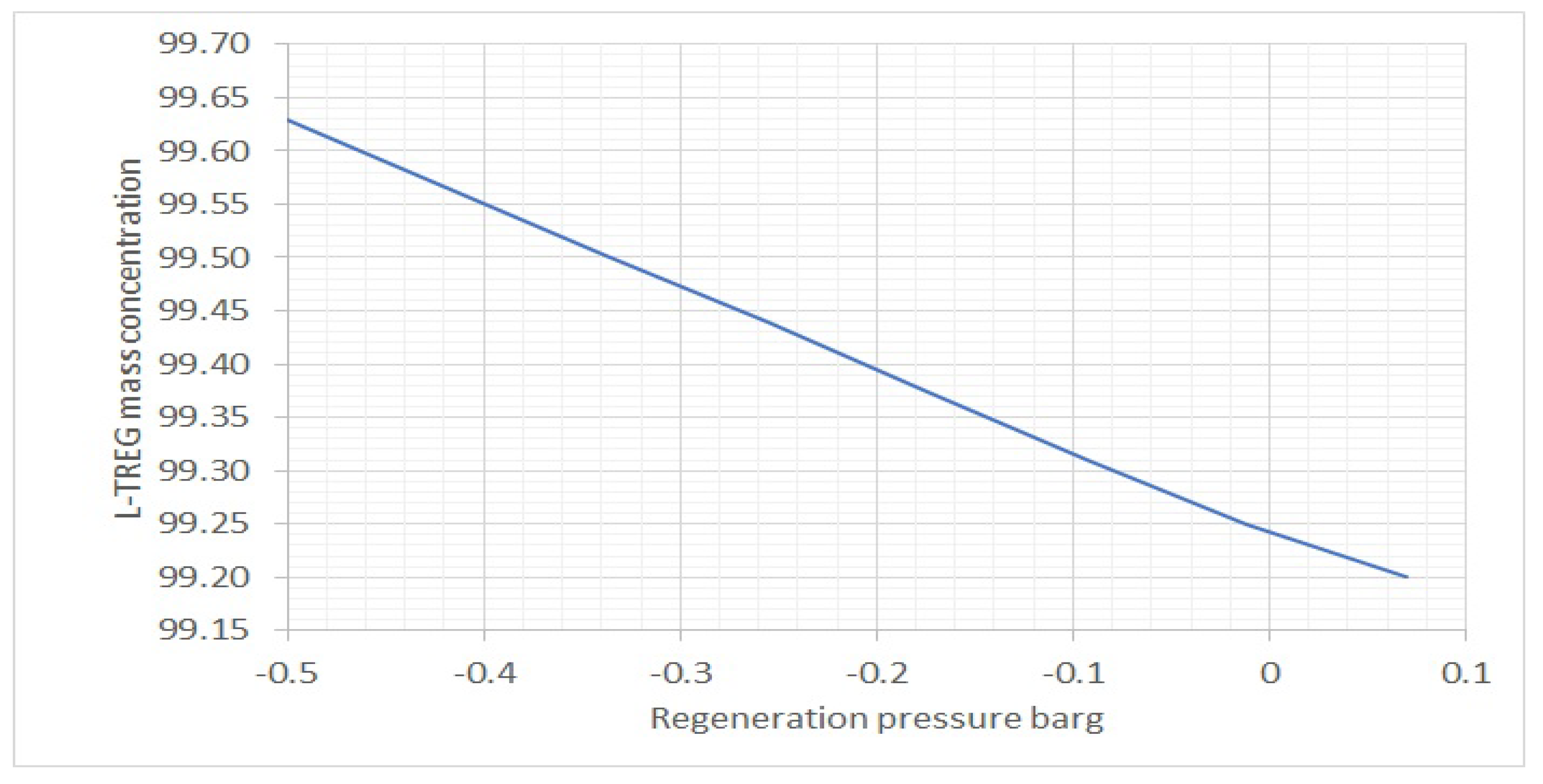
Figure 8 show that L-TEG 99.33 wt% is achievable for regeneration pressure equal −0.5 barg and that R-TEG (rich TEG) water concentration increase does not noticeably affect the achieved wt% L-TEG. The obtained results show that it is possible to regenerate the L-TEG to 99.18% mass concentration when a −0.4 barg negative pressure in the reboiler is created. This concentration of L-TEG is sufficient to dehydrate the gas at a pressure of 20 barg with a TEG circulation rate of 280 kg/h.
TEG circulation rate increase to 450 kg/h (up to the maximum circulation pump capacity) has a negligible effect on the value of the water dewpoint temperature
Table 2.
Very good results were obtained using TREG instead of TEG for gas dehydration. 99.2 wt% TREG could be achieved during atmospheric pressure regeneration. The dew point temperatures required by the PN-C-04752, 2011 standard for the gas working pressure of 20 barg, could be successfully achieved with 99.2 wt% TREG and circulation rate of 280 kg/h
Table 3.
TREG circulation rate has a much greater impact on the gas dewpoint temperature achieved than TEG. Dehydration of 15 barg working pressure gas and TREG circulation rate 450 kg/h where regeneration takes place near atmospheric pressure allows us to obtain approx. 7 °C lower gas dewpoint temperature than in the TEG unit for analogical conditions and TREG circulation rate 280 kg/h. Additional reduction in the TREG regeneration pressure to −0.2 barg allows one to obtain the gas dewpoint temperature required by the standard
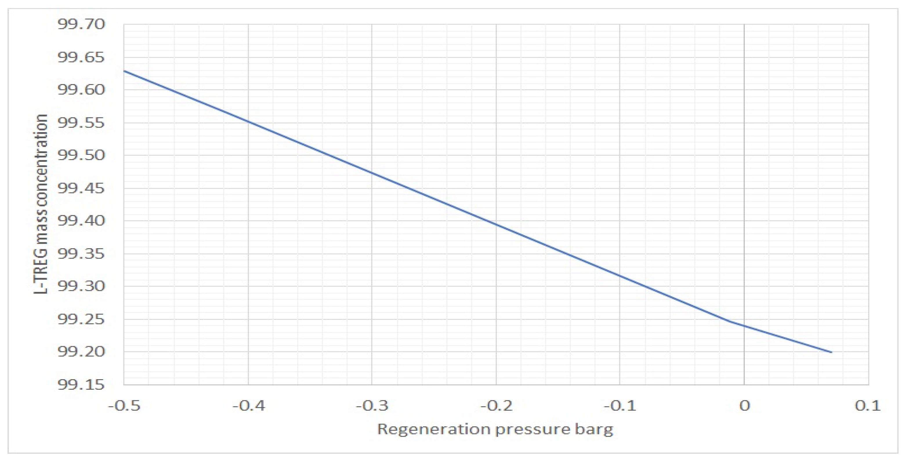
Table 4. The results presented in
Figure 10,
Figure 12 and
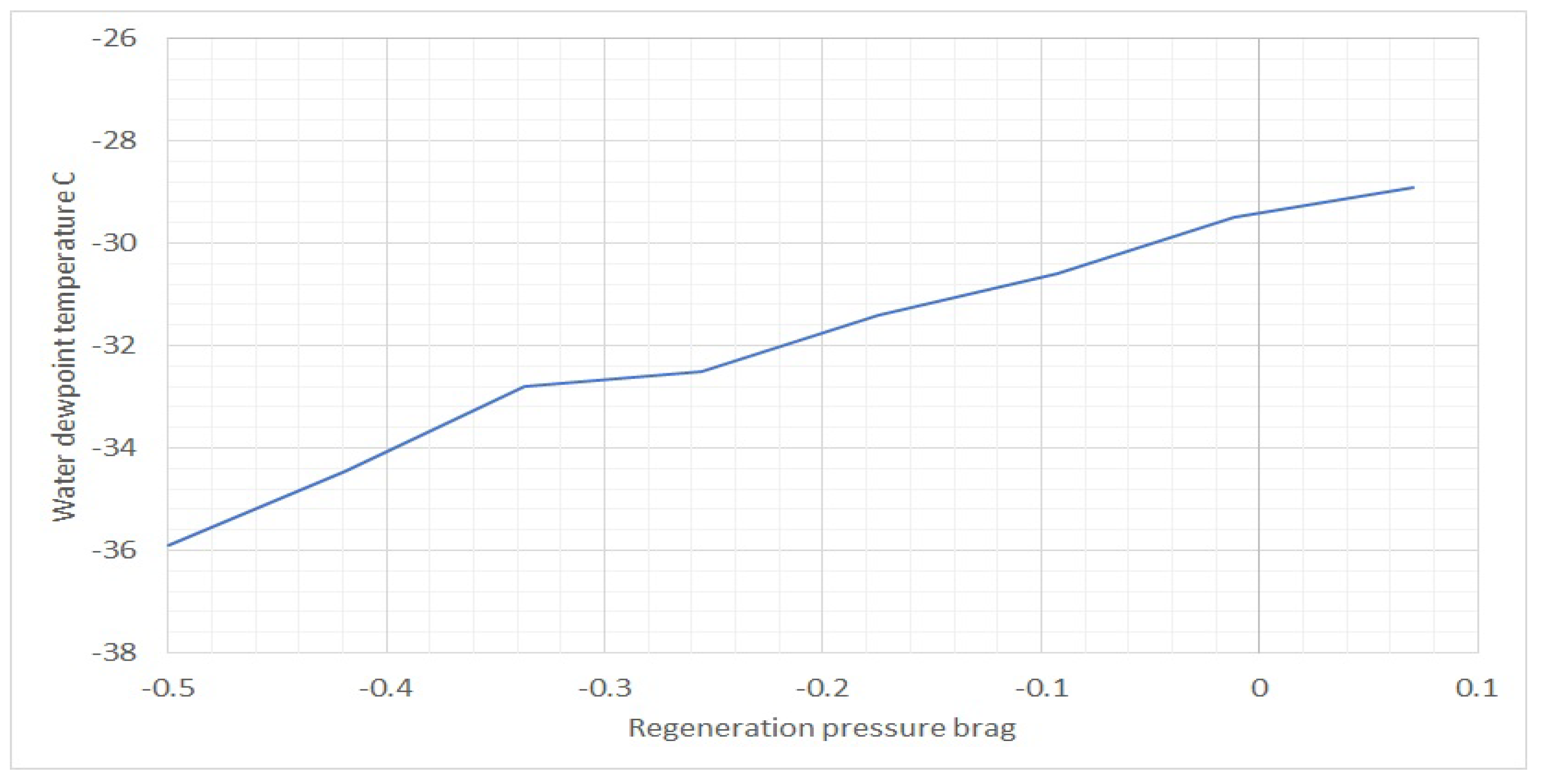
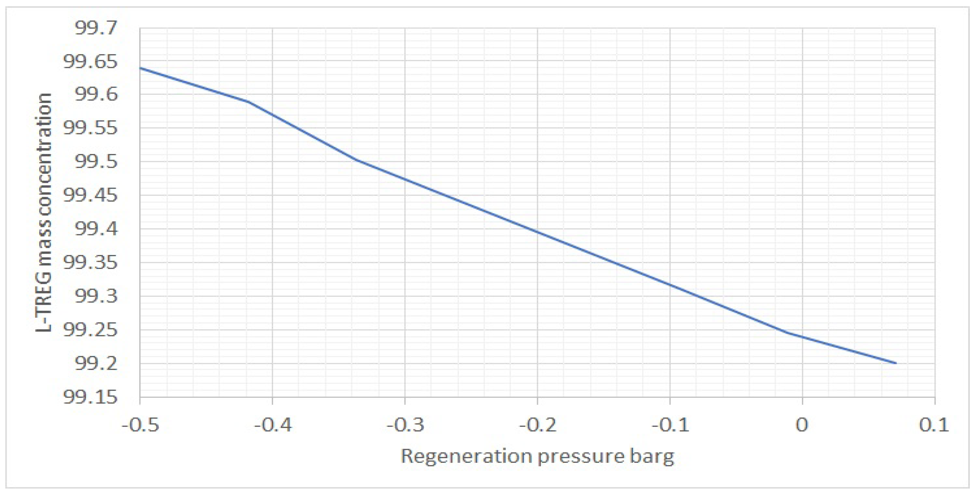
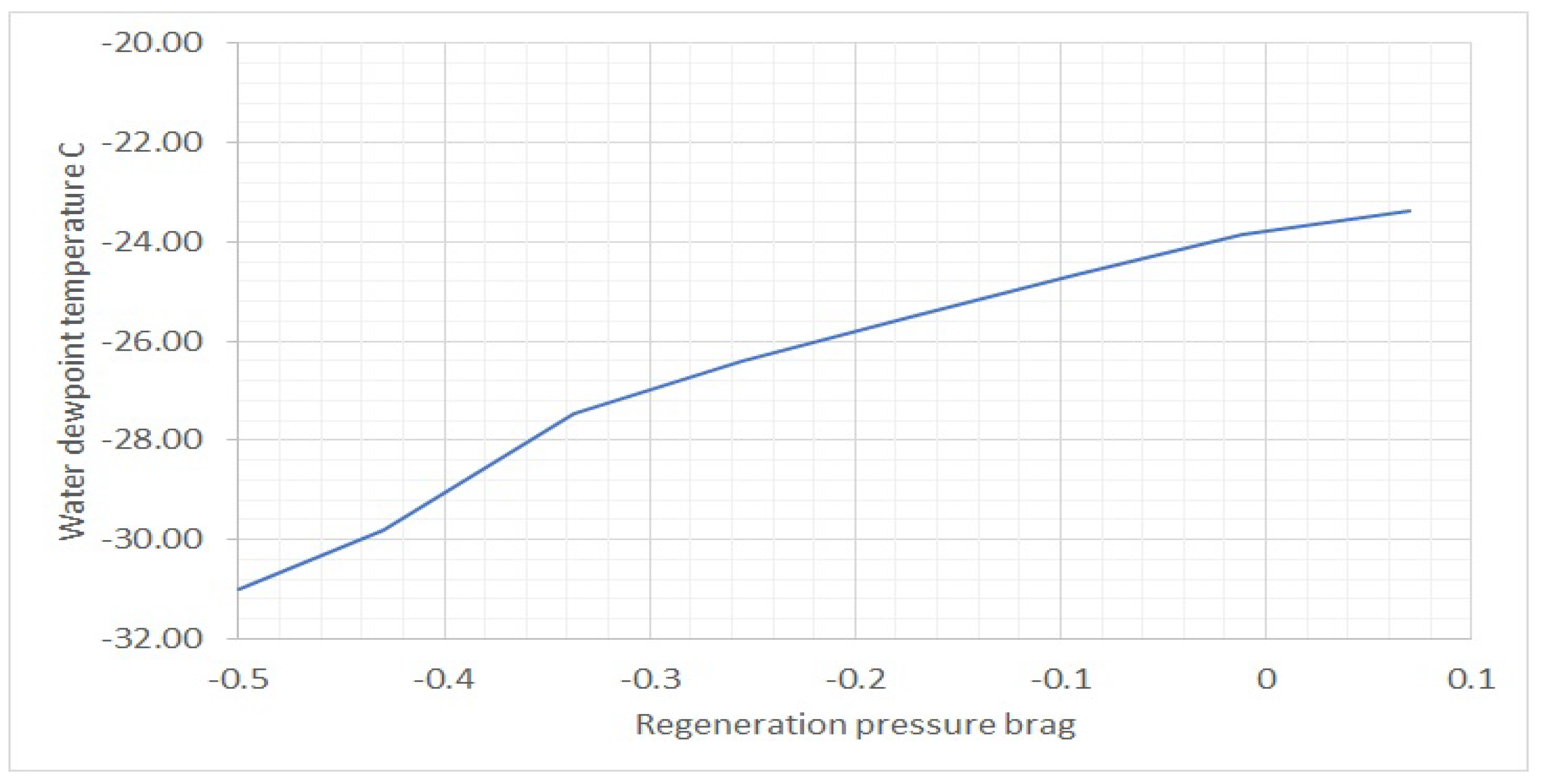
Figure 14 indicate clearly that L-TREG 99.63 wt% is achievable for regeneration pressure equal −0.5 barg and that R-TREG (rich TREG) water concentration increase does not affect noticeably achieved wt% L-TREG.
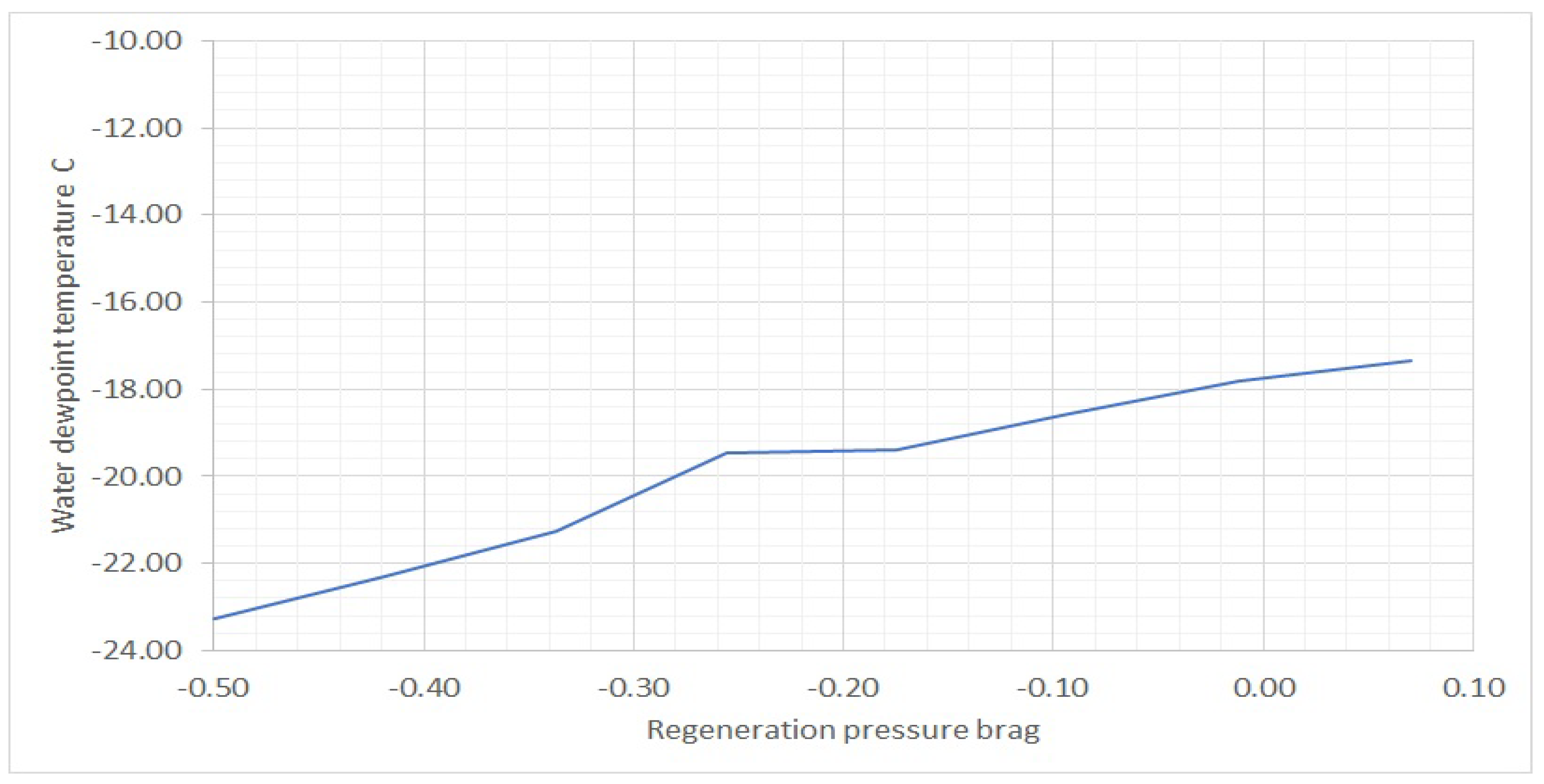
Overall, it is observed in
Figure 5,
Figure 7,
Figure 9,
Figure 11,
Figure 13 and
Figure 15 that glycol vacuum regeneration brings significant improvement to the dehydration processes. −27 °C, −26 °C, and −22.6 °C are the maximal achievable equilibrium water dewpoint temperature in the TEG unit and depend on the water content of the process gas. −36 °C, −31 °C, and −23.5 °C are results for the TREG unit, and dependence on the water content of process gas is analogical.
Process simulations demonstrated how important the energy efficiency of the ejector is in the place of its installation in the vapor flow line
Table 7,
Table 8,
Table 9 and
Table 10.
The position of the ejector at the end of the vapor flow line, downstream to the condensed water separator, allows for a significant reduction in motive gas consumption. Consequently, it significantly reduces energy consumption to create a vacuum in the regenerator.
The simulation results show that greater and greater amounts of motive gas are required to obtain the same pressure reduction value.
This relationship is nonlinear, but above −0.3 barg to −0.4 barg values of regeneration pressure, the motive gas (HP) consumption increases rapidly, and the regeneration pressure value approaches a constant value asymptotically.
The following inconveniences and problems could be eliminated when an ejector is used to create negative pressure in the regenerator to achieve higher L-TEG/L-TREG concentrations:
Loss of profits due to flaring wet stripping gas.
Additional emissions of stripping hydrocarbons that enhance the greenhouse effect.
Introducing flammable gases to the regenerator where a heat source is a flame tube eliminates additional operational risk.
Installation of a stripping column between the reboiler and surge tank, resulting in the necessity to arrange the vessels on platforms and build additional supporting structures and decks.
When hydrocarbons are used as stripping gas, an additional explosion hazard zone must be designated. Additional legal and technical restrictions are related to this.
Stripping gas needs to have sufficiently high pressure that exceeds the back pressure arising in between the gas injection point and the flare. In most cases, the regenerator must be qualified as a low-pressure vessel.
Vacuum pumps can be a nuisance.
When we decide to support our TEG/TREG regeneration unit with a vacuum-generating ejector, the following factors should be taken into account:
The thickness of the reboiler and the still column shell must be checked under internal negative pressure.
Regenerator and vent line flange and threaded connections should be additionally sealed.
The risk of accelerated TEG/TREG degradation when air enters the regenerator.
Protection of the glycol regenerator against the back air flow from the vent line.
Poorer glycol circulation pump working conditions. The pump will operate at reduced pressure on the suction side due to the negative pressure generated in the regenerator.
5. Conclusions
The calculations performed indicate that replacing TEG, which is the most commonly used absorbent, with TREG brings a noticeable effect of the increase in gas dehydration efficiency. TEG is suitable for picking up the necessary amount of water from the gas at a pressure of 30 barg and above, while glycol regeneration takes place near atmospheric pressure. TREG is suitable for dehydrating gas at lower working pressure, even 20 barg. The simulation results indicate that the optimal circulation rate of TEG and TREG varies significantly. Lean TEG circulation rate greater than 280 kg/h does not significantly lower the gas dewpoint temperatures. On the contrary, an increase in the lean TREG circulation rate to 450 kg/h brings a noticeable improvement in dehydration efficiency. In this way, the gas dewpoint temperature can be reduced by an additional 7 °C for dehydration run under 15 barg gas pressure
Table 3 and
Table 4.
The simulation results indicate that the use of an ejector to generate negative pressure in the regenerator, thus increasing the efficiency of TEG/TREG regeneration, is a cost-effective alternative to the other known methods such as striping gas, DRIZO, GLYNOXX, DRIGAS ™, ECOTEG ™, GOLDFINGER, and use of vacuum pumps. It is true within a certain operating range. This method is economically competitive considering the amount of ejector motive gas and thus moderate compression costs for lean TEG concentrations in the range of 98.4 wt% to 99.1 wt% and lean TREG in the range of 99.2 wt% to 99.55 wt%.
Based on the performed simulations, significant amounts of a motive gas are required to obtain a deep vacuum in the regenerator, which makes the process unprofitable
Table 7,
Table 8,
Table 9 and
Table 10.
The amount of an ejector motive gas strongly depends on the place of its installation in the distillation vapor flow line. It is more profitable to install the ejector downstream to the water condensate separator at the outlet of the vapor line to the atmosphere. The phase transformation elimination—water vapor condensation, which occurs in the ejector when it is placed downstream to the still column, leads to much smaller amounts of LP gas flowing through the ejector. The negative pressure limit values obtained in the regenerator range from about −0.3 barg to −0.4 barg. The demand for motive gas (HP) begins to increase rapidly for lower vacuum values, and the LP pressure in the regenerator tends asymptotically to a constant value.
For TREG regeneration with an ejector location downstream to the condensate separator, a higher pressure reduction value could be achieved with the same flow rate of the motive gas. This is a result of the lower solubility of hydrocarbons in TREG compared to that in TEG, and thus a lower flow rate of the LP gas
Table 7 and
Table 8.
However, it should be remembered that the ejector model is simplified, and the calculated demand for motive gas is approximate.
This paper demonstrated a completely new technique to increase the efficiency of the glycol dehydration unit. Presented technology is the subject of an ongoing patent procedure. Regeneration unit modifications can be relatively easily introduced in the working TEG/TREG dehydration plant, and their costs are significantly lower compared to most known methods of increasing efficiency. Apertures are characterized by the small weight and size of the final installation. This is due to the simplicity of the idea and the ejector itself. Regeneration unit modifications are introduced in its final section at the outlet of the vapor line to the atmosphere.
Very high concentrations of lean TEG/TREG could not be achieved cost-effectively with the air motive ejectors.


