
Electrochemically Structured Copper Current Collectors for Application in Energy Conversion and Storage: A Review


Abstract
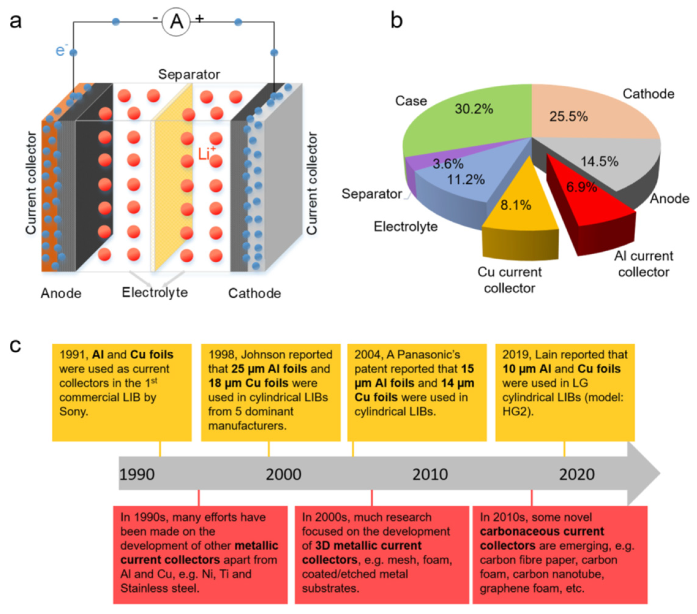
:1. Introduction
2. Electrochemical Methods for 3D Cu CC Formation
2.1. Template-Assisted Methods
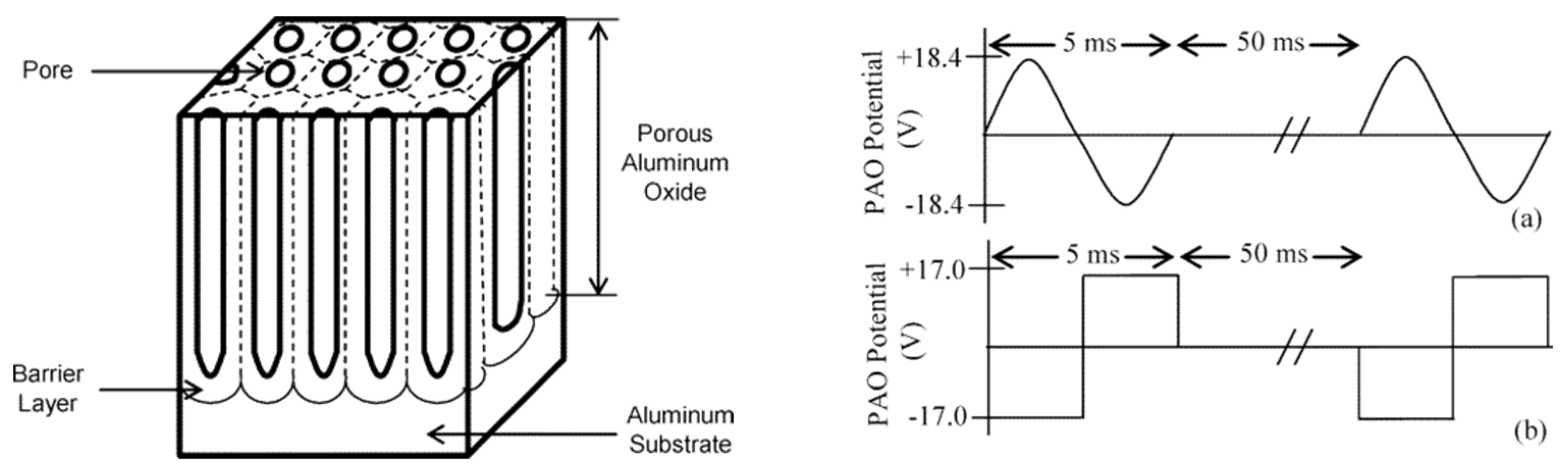
2.1.1. AAO Templates

2.1.2. Track-Etched Polymer Membrane Templates
2.1.3. Particle Templates
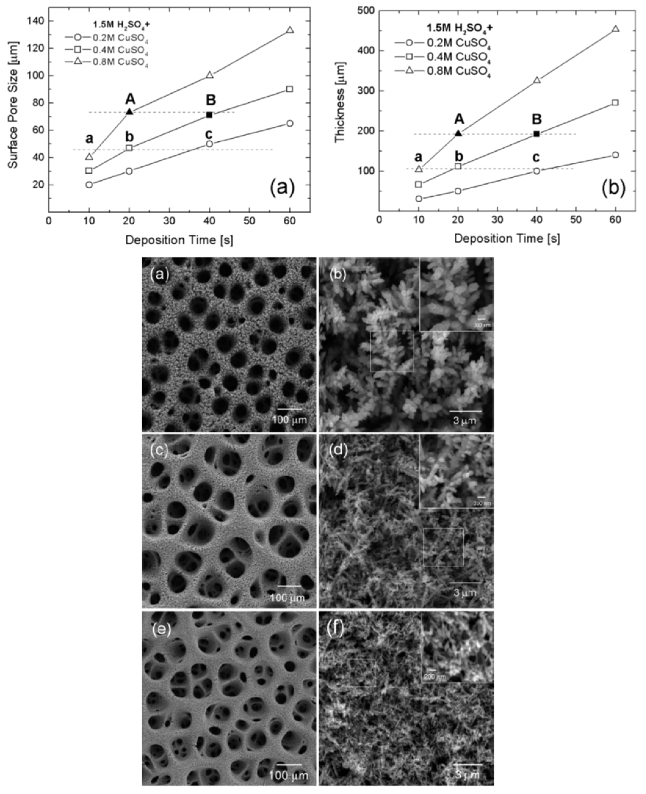
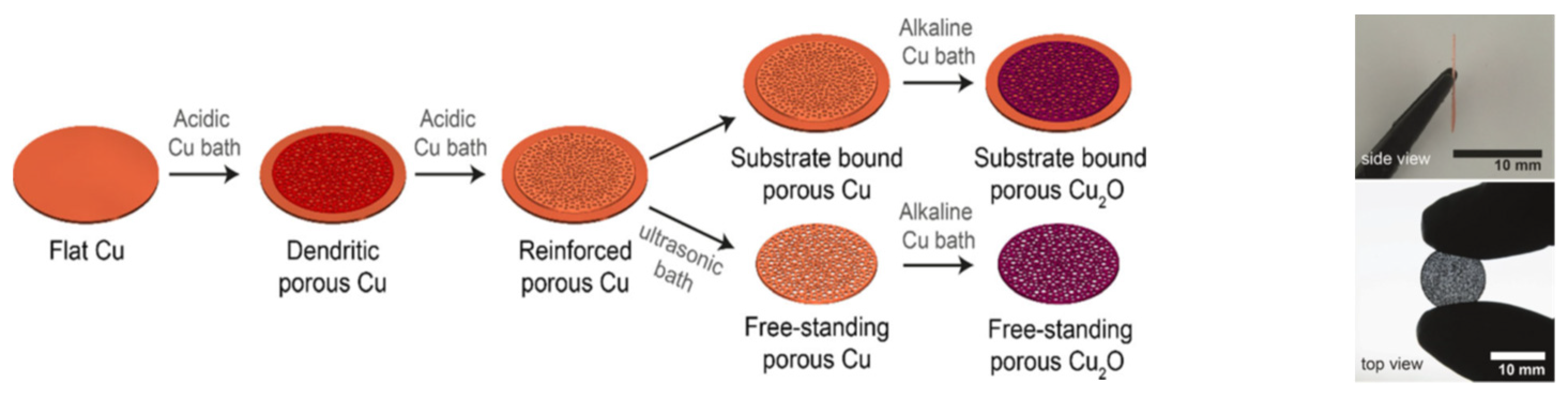
2.1.4. Dynamic Hydrogen Bubble Templates

| Electrolyte | Electrochemical Parameters | Cell Configuration/ Substrate | Cu Morphology | Ref. |
|---|---|---|---|---|
| 1.5 M H2SO4 0.2 M CuSO4 | DC galvanostatic max 3 A cm−2 | Two-electrode Cu cathode Cu anode | 3D microfoam nanostructured walls dpore = 40–100 μm | [71] |
| 0.2–0.8 M CuSO4 0.1–1.5 H2SO4 0.03–0.5 M CH3COOH 1–50 mM HCl | DC galvanostatic max 3 A cm−2 | Two-electrode Cu cathode Pt anode | 3D microfoam nanostructured walls dpore = 20–140 μm | [67] |
| 0.3 M CuSO4 0.7 M H2SO4 Additives: (NH4)2SO4, HCl, PEG(Mw2000), MPSA | DC galvanostatic 1–4 A cm−2 | Two-electrode Cu cathode Cu anode | 3D microfoam Wall morph. Depend on additive dpore = 10–40 μm | [69] |
| 0.4 M CuSO4 0.5 M H2SO4 CTAB (10 μM to 5 mM) | DC galvanostatic 0.1–1.2 A cm−2 | Three-electrode Au working Pt-counter SCE-reference | 3D microfoam nanostructured walls dpore = 50–150 μm; dpore (CTAB) = 10–40 μm | [68] |
| 0.5 M CuSO4 1.5 M H2SO4 0.1 M Na2SO4 | DC galvanostatic 4 A cm−2 2 A cm−2 | Two-electrode Cu-cathode Pt-anode | 3D microfoam nanostructured walls dpore, 2 Acm−2 = 25 μm; dpore, 4 Acm−2 = 40 μm | [72] |
| 0.1 M CuSO4 0.5 M H2SO4 Add: (NH4)2SO4, Na2SO4, NaCl, or CTAB | DC galvanostatic 2 A cm−2 | Two electrode Cu-cathode Cu-anode | 3D microfoam Wall morph. and dpore depend on additive | [73] |
| 0.2 M CuSO4 1 M H2SO4 | DC galvanostatic −0.075–−2.25 A cm−2 for 60 s and −20 mA cm−2 for 2 h (reinforcement) | Three-electrode Cu-working Pt-counter Ag/AlCl-reference | Free-standing porous Cu framework with through pore structure (various dpore) | [70] |
2.1.5. Summary of Section 2.1
2.2. Template-Free Methods
2.2.1. Electrochemical De-Alloying
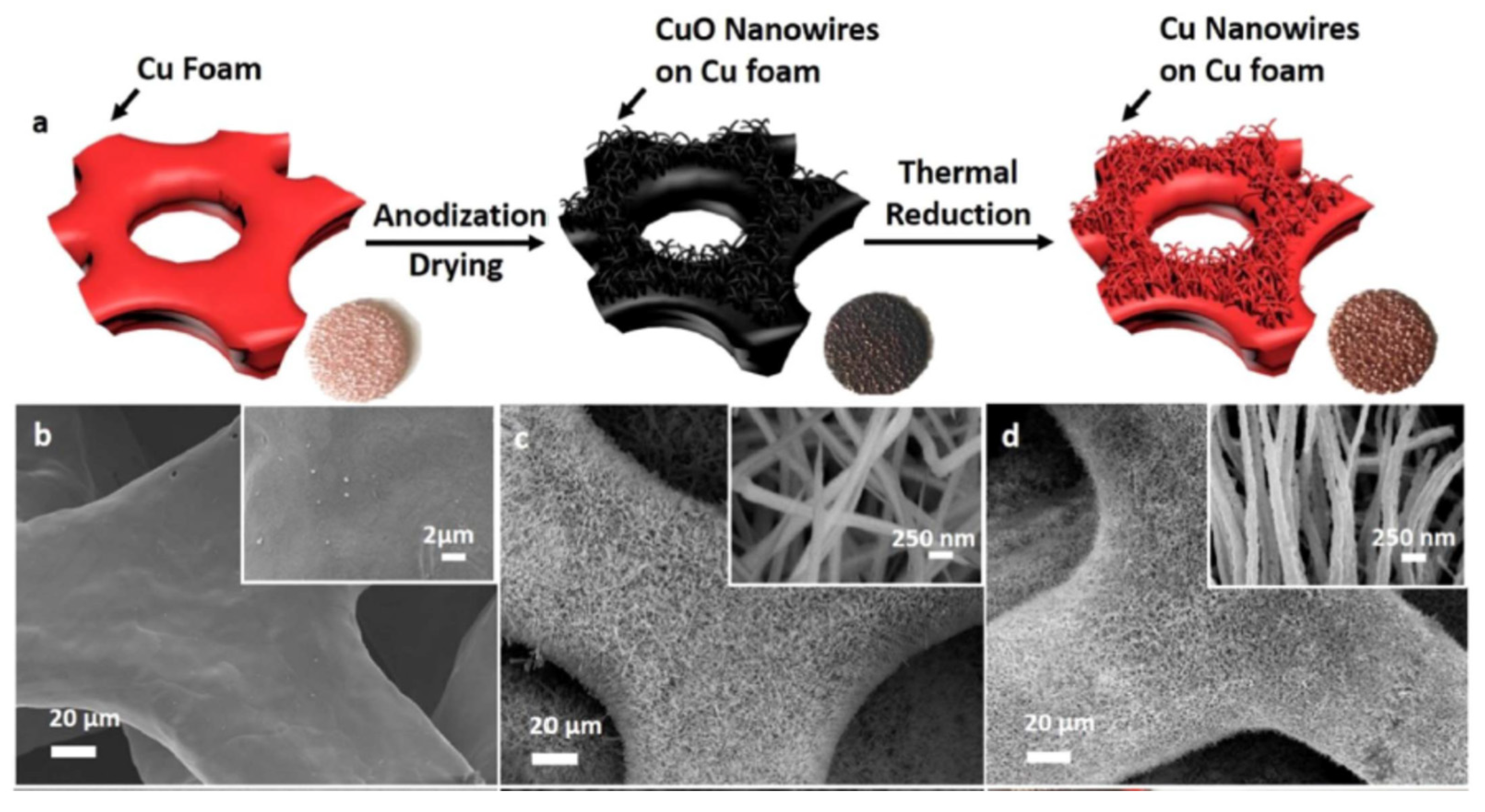
2.2.2. Anodic Treatment of Cu Substrate
Anodization
Anodic Treatment in Acid Electrolytes
2.2.3. Summary of Section 2.2
3. Electrochemical Characterization of 3D Cu CCs
3.1. Electrochemical Stability
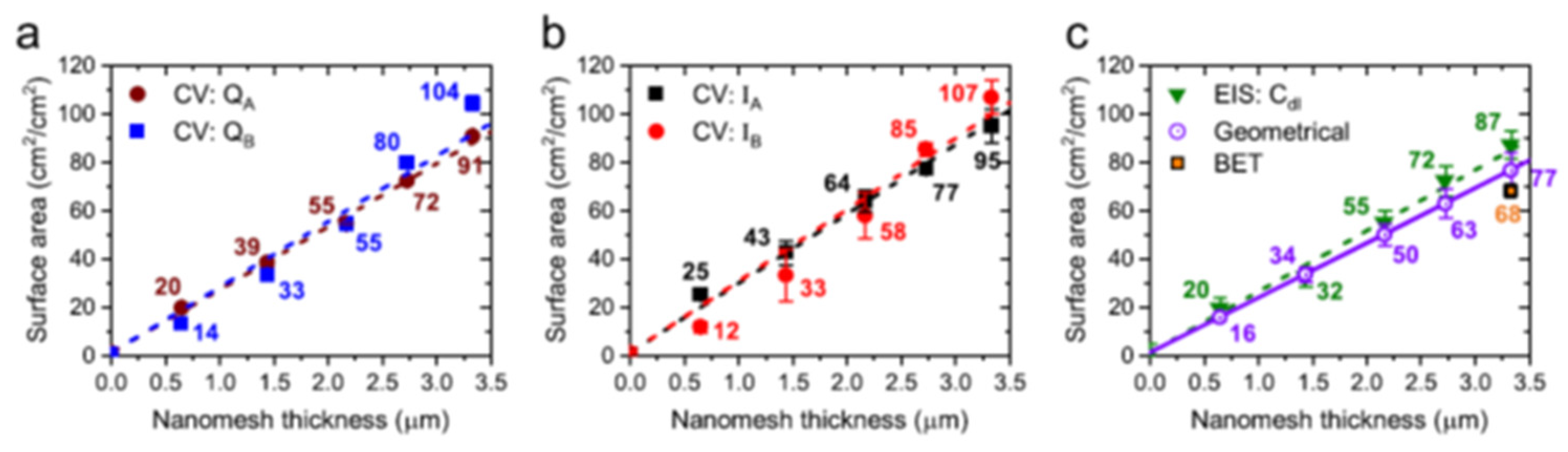
3.2. Surface Area
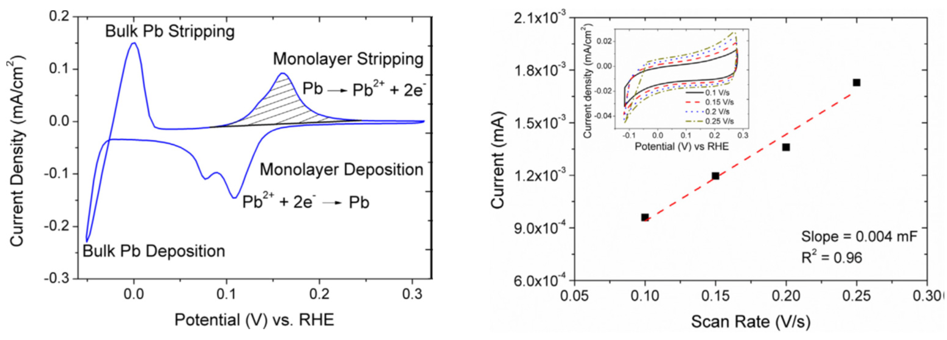
3.2.1. Underpotential Deposition of Pb
3.2.2. Double-Layer Capacitance
3.2.3. Cu Electro-Oxidation
3.3. Porosity
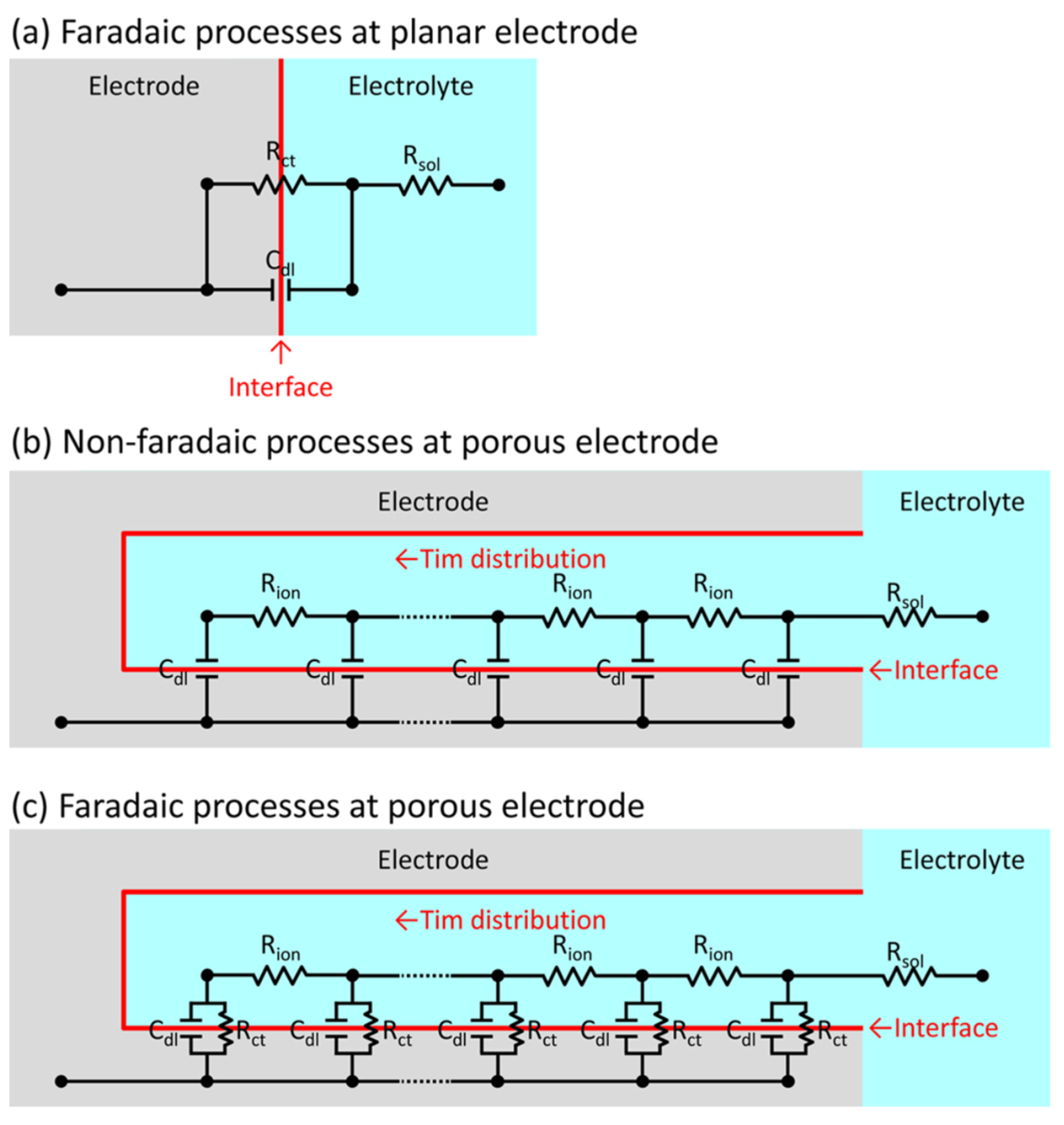
3.4. Ionic Transport
3.5. Summary of Section 3
4. Application of Structured Cu CCs in Energy Conversion and Storage
4.1. Electrocatalysis
4.1.1. Hydrogen Evolution Reaction (HER)
4.1.2. CO2 Reduction
4.2. Energy Storage
4.2.1. In Li Metal Battery Anodes
4.2.2. 3D Cu CCs for Si Anodes in Li Ion Batteries
4.2.3. Supercapacitors
4.3. Summary of Section 4
5. Conclusions and Outlook
- The most frequently used and important electrochemical methods for 3D Cu CC formation are presented. This comprises a brief overview of the methodological principles, followed by examples illustrating the conditions for their particular implementation (i.e., experimental setup, electrochemical parameters, electrolyte composition, and product morphology). Thus, the displayed information enables straightforward application of these strategies by a broad range of specialists in the field.
- DHBT is the simplest and most economical 3D Cu CC formation technique in comparison to the alternatives, which require template assembly and additional technological steps. This method utilizes relatively high deposition currents, essential for the intensive HER, which might require extra current boosting of the conventional potentiostat/galvanostat devices. Furthermore, a second dendrite reinforcement step is necessary to achieve better mechanical stability of the structure, which offers the possibility of forming free-standing 3D Cu CCs. The large active surface area of 3D Cu CCs with dendrites is highly beneficial for energy conversion and sensing devices, while due to their reinforced mechanical strength free-standing 3D Cu CCs provide unique features that can be utilized in closed and compact cells, e.g., battery cells (cylindrical, coin, and pouch cells) and/or stack electrochemical cells (electrolyzer or reduction cells). The formation of free-standing 3D Cu CCs opens up new possibilities for the development of various interesting electrochemical applications.
- Electrochemical characterization of the active surface and porosity of 3D Cu CCs is a simple and low-cost approach. However, it remains an underexplored area in terms of establishing the limits of these methods for the analysis of different 3D Cu types. In order to associate the functional behavior of 3D Cu CCs with their structural properties, quantitative data about the electrochemically active surface area, porosity, and ionic transport in the porous structure are required. This can assist in comparing materials obtained by different methods and make analysis less empirical.
- Electrochemically obtained 3D Cu CCs have demonstrated their application in multiple fields, including Li ion batteries, HER, CO2 reduction, etc. The 3D Cu structures formed by means of the DHBT, AAO template, and electrochemical de-alloying methods present comparable performance as CCs for anodes in Li metal batteries. However, owing to its simplicity, the DHBT approach is more frequently applied, and is preferred for research. Electrochemically structured 3D Cu CCs enable reduction of the local current density and reaction overpotential, mechanical stabilization of the deposited functional material during operation, and the possibility of additional modification. Furthermore, the effortless integration of an active electrocatalyst into 3D Cu CCs makes them greatly attractive for important applications with high energy and environmental impact.
Author Contributions
Funding
Data Availability Statement
Conflicts of Interest
Abbreviations
| AAO | Anodic aluminum oxide |
| AC | Alternating current |
| ALD | Atomic layer deposition |
| BET | Brunauer, Emmett, and Teller theory |
| [BMP][TFSI] | 1-Butyl-1-methylpyrrolidinium bis(trifluoromethylsulfonyl)imide |
| [BMP][DCA] | 1-Butyl-1-methylpyrrolidinium dicyanamide |
| [BMIm][DCA] | 1-Butyl-3-methylimidazolium dicyanamide |
| [BMIm][TFSI] | 1-butyl-3-methylimidazolium-bis(trifluormethylsulfonyl)imide |
| C1 | Compounds with one C atom (methane, methanol) |
| C2 | Compounds with two C atoms (ethane, ethene, ethanol) |
| C3 | Compounds with three C atoms (propane, propylene, propyl alcohol) |
| CC | Current collector |
| CE | Counter electrode |
| CTAB | Cetyltrimethylammonium bromide |
| Cuf | Copper foam |
| CV | Cyclic voltammetry |
| CVD | Chemical vapor deposition |
| 3D | Three-dimensional |
| DC | Direct current |
| DETA | Diethylenetriamine |
| DHBT | Dynamic hydrogen bubble template |
| EIS | Electrochemical impedance spectroscopy |
| EDL | Electrical double layer |
| [EMIm][TFSI] | 1-Ethyl-3-methylimidazolium-bis(trifluormethylsulfonyl)imide |
| EMIC | 1-ethyl-3-methyl Imidazolium Chloride |
| EPD | Electrophoretic deposition |
| FE | Faradic efficiency |
| FTO | Fluorine (doped) tin oxide |
| HER | Hydrogen evolution reaction |
| IO | Inverse opal |
| ITO | Indium tin oxide |
| LIB | Li ion battery |
| MPSA | 3-mercapto-1-propane sulfonic acid |
| NW | Nanowire |
| PC | Polycarbonate |
| p-Cu | Porous copper |
| PEG | Polyethylene glycol |
| PET | Polyethylene thereftalate |
| PVD | Physical vapor deposition |
| PMMA | Polymethyl methacrylate |
| PVDF | Polyvinylidene fluoride |
| PP | Polypropylene |
| PI | Polyimide |
| PS | Polystyrene |
| RE | Reference electrode |
| SCE | Saturated calomel electrode |
| SHE | Standard hydrogen electrode |
| SDS | Sodium dodecyl sulfate |
| SEM | Scanning electron microscopy |
| SS | Stainless steel |
| TFM | Transmission electron microscopy |
| TMO | Transition metal oxide |
| TLM | Transmission line model |
| UPD | Under potential deposition |
| WE | Working electrode |
| Symbols | |
| E0 | Equilibrium potential |
| AECSA | Electrochemically active surface area |
| Cref | Area-specific reference capacitance |
| P | Porosity |
| Vtotal | Geometrical volume of material |
| Vpore | Pore volume |
| Vsolid | Volume of solid metal |
| Rsol | Electrolyte bulk resistance |
| Rion | Electrolyte resistance in the pores |
| Cdl | Electrical double layer capacitance |
| Rct | Charge transfer resistance |
| ω | Angular frequency |
| r | Pore radius |
| L | Pore length |
| Znonfaradic | Non-Faradaic impedance |
| Zfaradic | Faradaic impedance |
References
- Zhu, P.; Gastol, D.; Marshall, J.; Sommerville, R.; Goodship, V.; Kendrick, E. A review of current collectors for lithium-ion batteries. J. Power Source 2021, 485, 229321. [Google Scholar] [CrossRef]
- Das, M.; Biswas, A.; Purkait, T.; Boruah, T.; Bhardwaj, S.; Das, S.K.; Dey, R.S. The versatility of the dynamic hydrogen bubble template derived copper foam on the emerging energy applications: Progress and future prospects. J. Mater. Chem. A 2022, 10, 13589–13624. [Google Scholar] [CrossRef]
- Shi, C.; Yu, M. Flexible solid-state lithium-sulfur batteries based on structural designs. Energy Storage Mater. 2023, 57, 429–459. [Google Scholar] [CrossRef]
- Yue, Y.; Liang, H. 3D Current Collectors for Lithium-Ion Batteries: A Topical Review. Small Methods 2018, 2, 1800056. [Google Scholar] [CrossRef]
- Kim, M.J.; Cruz, M.A.; Yang, F.; Wiley, B.J. Accelerating electrochemistry with metal nanowires. Curr. Opin. Electrochem. 2019, 16, 19–27. [Google Scholar] [CrossRef]
- Li, D.; Chen, B.; Hu, H.; Lai, W.-Y. Constructing 3D Porous Current Collectors for Stable and Dendrite-Free Lithium Metal Anodes. Adv. Sustain. Syst. 2022, 6, 2200010. [Google Scholar] [CrossRef]
- Shi, Q.; Lu, C.; Cao, Y.; Hao, Y.; Bachmatiuk, A.; Rümeli, M.H. Recent developments in current collectors for lithium metal anodes. Mater. Chem. Front. 2023, 7, 1298–1311. [Google Scholar] [CrossRef]
- Wang, N.; Hang, T.; Ling, H.; Hu, A.; Li, M. High-performance Si-based 3D Cu nanostructured electrode assembly for rechargeable lithium batteries. J. Mater. Chem. A 2015, 3, 11912–11919. [Google Scholar] [CrossRef]
- Liu, Y.; Goebla, J.; Yin, Y. Templated synthesis of nanostructured materials. Chem. Soc. Rev. 2013, 42, 2610. [Google Scholar] [CrossRef]
- Lu, C.; Qi, L.; Yang, J.; Zhang, D.; Wu, N.; Ma, J. Simple Template-Free Solution Route for the Controlled Synthesis of Cu(OH)2 and CuO Nanostructures. J. Phys. Chem. B 2004, 108, 17825–17831. [Google Scholar] [CrossRef]
- Pu, J.; Shen, Z.; Zhong, C.; Zhou, Q.; Liu, J.; Zhu, J.; Zhang, H. Electrodeposition Technologies for Li-Based Batteries: New Frontiers of Energy Storage. Adv. Mater. 2020, 32, 1903808. [Google Scholar] [CrossRef] [PubMed]
- Sarkar, J.; Khan, G.; Basumallick, A. Nanowires: Properties, applications, and synthesis via porous anodic aluminium oxide template. Bull. Mater. Sci. 2007, 30, 271–290. [Google Scholar] [CrossRef] [Green Version]
- Masuda, H.; Fukuda, K. Ordered Metal Nanohole Arrays Made by a Two-Step Replication of Honeycomb Structures of Anodic Alumina. Science 1995, 228, 1466–1468. [Google Scholar] [CrossRef] [PubMed]
- Lee, W.; Park, S. Porous Anodic Aluminum Oxide: Anodization and Templated Synthesis of Functional Nanostructures. Chem. Rev. 2014, 114, 7487–7556. [Google Scholar] [CrossRef]
- Duan, H.; Gnanaraj, J.; Chena, X.; Li, B.; Lianga, J. Fabrication and characterization of Fe3O4-based Cu nanostructured electrode for Li-ion battery. J. Power Source 2008, 185, 512–518. [Google Scholar] [CrossRef]
- Davydov, N.D.; Sattari, P.A.; AlMawlawi, D.; Osika, A.; Haslett, T.L.; Moskovits, M. Field emitters based on porous aluminum oxide templates. J. Appl. Phys. 1999, 86, 3983–3987. [Google Scholar] [CrossRef] [Green Version]
- Li, X.; Wang, Y.; Song, G.; Peng, Z.; Yu, Y.; She, X.; Sun, J.; Li, J.; Li, P.; Wang, Z.; et al. Fabrication and Magnetic Properties of Ni/Cu Shell/Core Nanocable Arrays. J. Phys. Chem. C 2010, 114, 6914–6916. [Google Scholar] [CrossRef]
- Chang, R.; Zheng, L.; Wang, C.; Yang, D.; Zhang, G.; Sun, S. Synthesis of Hierarchical Platinum-Palladium-Copper Nanodendrites for Efficient Methanol Oxidation. Appl. Catal. B 2017, 211, 205–211. [Google Scholar] [CrossRef]
- Sulka, G.D.; Stroobants, S.; Moshchalkov, V.; Borghs, G.; Celisd, J. Synthesis of Well-Ordered Nanopores by Anodizing Aluminum Foils in Sulfuric Acid. J. Electrochem. Soc. 2002, 149, D97–D103. [Google Scholar] [CrossRef]
- Sulka, G.D.; Stepniowski, W. Structural features of self-organized nanopore arrays formed by anodization of aluminum in oxalic acid at relatively high temperatures. Electrochim. Acta 2009, 54, 3683–3691. [Google Scholar] [CrossRef]
- Zaraska, L.; Sulka, G.D.; Jaskuła, M. The effect of n-alcohols on porous anodic alumina formed by self-organized two-step anodizing of aluminum in phosphoric acid. Surf. Coat. Technol. 2010, 204, 1729–1737. [Google Scholar] [CrossRef]
- Zaraska, L.; Sulka, G.D.; Jaskuła, M. Fabrication of free-standing copper foils covered with highly-ordered copper nanowire arrays. Appl. Surf. Sci. 2012, 258, 7781–7786. [Google Scholar] [CrossRef]
- Eftekhari, A. (Ed.) Nanostructured Materials in Electrochemistry; Wiley-VCH: Weinheim, Germany, 2008; pp. 1–116. ISBN 978-3-527-31876-6. [Google Scholar]
- Chowdhury, T.; Casey, D.P.; Rohan, J.F. Additive influence on Cu nanotube electrodeposition in anodised aluminium oxide templates. Electrochem. Commun. 2009, 11, 1203–1206. [Google Scholar] [CrossRef] [Green Version]
- Gerein, N.J.; Haber, J.A. Effect of ac Electrodeposition Conditions on the Growth of High Aspect Ratio Copper Nanowires in Porous Aluminum Oxide Templates. J. Phys. Chem. B 2005, 109, 17372–17385. [Google Scholar] [CrossRef] [PubMed]
- Gelves, G.A.; Lin, B.; Sundararaj, U.; Haber, J.A. Low Electrical Percolation Threshold of Silver and Copper Nanowires in Polystyrene Composites. Adv. Funct. Mater. 2006, 16, 2423–2430. [Google Scholar] [CrossRef]
- Taberna, P.L.; Mitra, S.; Poizot, P.; Simon, P.; Tarascon, J.-M. High rate capabilities Fe3O4-based Cu nano-architectured electrodes for lithium-ion battery applications. Nat. Mater. 2006, 5, 567–573. [Google Scholar] [CrossRef] [Green Version]
- Ramírez, C.; Bozzini, B.; Calderón, J.A. Electrodeposition of copper from triethanolamine as a complexing agent in alkaline solution. Electrochim. Acta 2022, 425, 140654. [Google Scholar] [CrossRef]
- Chen, X.; Duan, H.; Zhou, Z.; Liang, J.; Gnanaraj, J. Fabrication of free-standing Cu nanorod arrays on Cu disc by template-assisted electrodeposition. Nanotechnology 2008, 19, 365306. [Google Scholar] [CrossRef]
- Liu, H.; Meng, Y.S.; Li, Q. Three-dimensional nanocable arrays with a copper core and cupric oxide shell for high power lithium ion batteries. RSC Adv. 2013, 3, 11586–11593. [Google Scholar] [CrossRef]
- Rehnlund, D.; Pettersson, J.; Edström, K.; Nyholm, L. Lithium Trapping in Microbatteries Based on Lithium- and Cu2O-Coated Copper Nanorods. ChemistrySelect 2018, 3, 2311–2314. [Google Scholar] [CrossRef]
- Brzózka, A.; Szeliga, D.; Kurowska-Tabor, E.; Sulka, G.D. Synthesis of copper nanocone array electrodes and its electrocatalytic properties toward hydrogen peroxide reduction. Mater. Lett. 2016, 174, 66–70. [Google Scholar] [CrossRef]
- Huang, B.-R.; Yeh, C.-S.; Wang, D.-C.; Tan, J.T.; Sung, J. Field emission studies of amorphous carbon deposited on copper nanowires grown by cathodic arc plasma deposition. New Carbon Mater. 2009, 24, 97–101. [Google Scholar] [CrossRef]
- Lim, J.; Kim, K.-H.; Cojocaru, C.-S. Highly uniform, straightforward, controllable fabrication of copper nano-objects via artificial nucleation-assisted electrodeposition. J. Electroanal. Chem. 2021, 897, 1155946. [Google Scholar] [CrossRef]
- Teshima, H.; Kojima, K.; Ju, Y. Fabrication of Anodic Aluminum Oxide Template and Copper Nanowire Surface Fastener. J. Electron. Packag. 2014, 136, 044501. [Google Scholar] [CrossRef]
- Stepniowski, W.J.; Moneta, M.; Karczewski, K.; Michalska-Domanska, M.; Czujko, T.; Mol, J.M.C.; Buijnsters, J.G. Fabrication of copper nanowires via electrodeposition in anodic aluminum oxide templates formed by combined hard anodizing and electrochemical barrier layer thinning. J. Electroanal. Chem. 2018, 809, 59–66. [Google Scholar] [CrossRef] [Green Version]
- Ma, T.; Janot, J.-M.; Balme, S. Track-Etched Nanopore/Membrane: From Fundamental to Applications. Small Methods 2020, 4, 2000366. [Google Scholar] [CrossRef]
- Fleischer, R.L.; Price, P.B.; Symes, E.M. Novel Filter for Biological Materials. Science 1964, 143, 249–250. [Google Scholar] [CrossRef]
- Motoyama, M.; Fukunaka, Y.; Sakka, T.; Ogata, Y.H.; Kikuchi, S. Electrochemical processing of Cu and Ni nanowire arrays. J. Electroanal. Chem. 2005, 584, 84–91. [Google Scholar] [CrossRef]
- Chlebny, I.; Doudin, B.; Ansermet, J.-P. Pore size distributions of nanoporous track-etched membranes. Nanostructured Mater. 1993, 2, 637–642. [Google Scholar] [CrossRef]
- Azarian, A.; Irajizad, A.; Dolati, A.; Ghorbani, M. Time dependence of the surface plasmon resonance of copper nanorods. J. Phys. Condens. Matter 2007, 19, 446007. [Google Scholar] [CrossRef]
- Enculescu, I.; Siwy, Z.; Dobrev, D.; Trautmann, C.; Toimil Molares, M.-E.; Neumann, R.; Hjort, K.; Westerberg, L.; Spohr, R. Copper nanowires electrodeposited in etched single-ion track templates. Appl. Phys. A 2003, 77, 751–755. [Google Scholar] [CrossRef]
- Kaur, R.; Verma, N.K.; Kumar, S. Fabrication of copper microcylinders in polycarbonate membranes and their characterization. J. Mater. Sci. 2006, 41, 3723–3728. [Google Scholar] [CrossRef]
- Kaur, R.; Singh, S.; Kaur, J.; Kumar, R. Study of Variation in Pore Diameter with Etching Rate and Fabrication of Copper Nano/Micro Wires Using Electrodeposition Method. Polym. Plast. Technol. Eng. 2012, 51, 1193–1197. [Google Scholar] [CrossRef]
- Motoyama, M.; Fukunaka, Y.; Sakka, T.; Ogata, Y.H. Initial stages of electrodeposition of metal nanowires in nanoporous templates. Electrochim. Acta 2007, 53, 205–212. [Google Scholar] [CrossRef]
- Riveros, G.; Gómez, H.; Schrebler, R.; Marotti, R.E.; Dalchiele, E.A. An In Situ EIS Study during the Electrochemical Growth of Copper Nanowires into Porous Polycarbonate Membranes. Electrochem. Solid-State Lett. 2008, 11, K19–K23. [Google Scholar] [CrossRef]
- Dauginet-De Pra, L.; Ferain, E.; Legras, R.; Demoustier-Champagne, S. Fabrication of a new generation of track-etched templates and their use for the synthesis of metallic and organic nanostructures. Nucl. Instrum. Methods Phys. Res. Sect. B 2002, 196, 81–88. [Google Scholar] [CrossRef]
- Duan, J.; Liu, J.; Mo, D.; Yao, H.; Maaz, K.; Chen, Y.; Sun, Y.; Hou, M.; Qu, X.; Zhang, L.; et al. Controlled crystallinity and crystallographic orientation of Cu nanowires fabricated in ion-track templates. Nanotechnology 2010, 21, 365605. [Google Scholar] [CrossRef]
- Gambirasia, A.; Cattarin, S.; Musiani, M.; Vázquez-Gómeza, L.; Verlatoa, L. Direct electrodeposition of metal nanowires on electrode surface. Electrochim. Acta 2011, 56, 8582–8588. [Google Scholar] [CrossRef]
- Denkov, N.D.; Velev, O.D.; Kralchevsky, P.A.; Ivanov, I.B.; Yoshimura, H.; Nagayama, K. Mechanism of Formation of Two-Dimensional Crystals from Latex Particles on Substrates. Langmuir 1992, 8, 3183–3190. [Google Scholar] [CrossRef]
- Juárez, B.H.; García, P.D.; Golmayo, D.; Blanco, A.; López, C. ZnO Inverse Opals by Chemical Vapor Deposition. Adv. Mater. 2005, 17, 2761–2765. [Google Scholar] [CrossRef] [Green Version]
- Wijnhoven, J.E.G.J.; Zevenhuizen, S.J.M.; Hendriks, M.A.; Vanmaekelbergh, D.; Kelly, J.J.; Vos, W.L. Electrochemical Assembly of Ordered Macropores in Gold. Adv. Mater. 2000, 12, 888. [Google Scholar] [CrossRef]
- Ding, L.; Yu-Ren, W.; Yong, Y.; Wen-Jie, M.; Cheng, L. Improving nucleation in the fabrication of high-quality 3D macro-porous copper film through the surface-modification of a polystyrene colloid-assembled template. Chin. Phys. 2007, 16, 468. [Google Scholar] [CrossRef]
- Ding, L.; Yuren, W.; Wenjie, M.; He, C.; Taohua, X.; Can, Y. The key factors in fabrication of high-quality ordered macroporous copper film. Appl. Surf. Sci. 2008, 254, 6775–6778. [Google Scholar] [CrossRef]
- Barako, M.T.; Weisse, J.M.; Roy, S.; Kodama, T.; Dusseault, T.J.; Motoyama, M.; Asheghi, M.; Prinz, F.B.; Zheng, X.; Goodson, K.E. Thermal conduction in nanoporous copper inverse opal films. In Proceedings of the Fourteenth Intersociety Conference on Thermal and Thermomechanical Phenomena in Electronic Systems (ITherm), Orlando, FL, USA, 27–30 May 2014; pp. 736–743. [Google Scholar] [CrossRef]
- Tsai, M.-C.; Zhuanga, D.-X.; Chen, P.-Y. Electrodeposition of macroporous silver films from ionic liquids and assessment of these films in the electrocatalytic reduction of nitrate. Electrochim. Acta 2010, 55, 1019–1027. [Google Scholar] [CrossRef]
- El Abedin, S.Z.; Prowald, A.; Endres, F. Fabrication of highly ordered macroporous copper films using template-assisted electrodeposition in an ionic liquid. Electrochem. Commun. 2012, 18, 70–72. [Google Scholar] [CrossRef]
- Bassetto, V.C.; Russell, A.E.; Kubota, L.T.; Bartlett, P.N. Preparation of copper sphere segment void templates for electrochemical SERS and their use to study the interaction of amino acids with copper under potentiostatic control. Electrochim. Acta 2014, 144, 400–405. [Google Scholar] [CrossRef] [Green Version]
- Song, H.; Im, M.; Song, J.T.; Lim, J.-A.; Kim, B.S.; Kwo, Y.; Jihun, S.R. Effect of Mass Transfer and Kinetics in Ordered Cu-Mesostructures for Electrochemical CO2 Reduction. Appl. Catal. B Environ. 2018, 232, 391–396. [Google Scholar] [CrossRef]
- Zhang, C.; Palko, J.W.; Rong, G.; Pringle, K.S.; Barako, M.T.; Dusseault, T.J.; Asheghi, M.; Santiago, J.G.; Goodson, K.E. Tailoring Permeability of Microporous Copper Structures through Template Sintering. ACS Appl. Mater. Interfaces 2018, 10, 30487–30494. [Google Scholar] [CrossRef]
- Wu, H.; Zheng, L.; Liu, W.; Xia, X.; Xiao, C.; Xie, J.; Su, L.; Wang, L.; Du, N. Three-dimensional porous copper framework supported group IVA element materials as sodium-ion battery anode materials. J. Alloys Compd. 2019, 771, 169–175. [Google Scholar] [CrossRef]
- Meng, X.; Song, Y.; Shu, T. Morphology control and optical characterization of three-dimensional ordered macroporous Cu films from template-assisted electrodeposition. J. Porous Mater. 2020, 27, 1069–1076. [Google Scholar] [CrossRef]
- Zhou, Y.; Zhao, J.; Liu, Y.; Ng, R.J.H.; Yang, J.K.W. Optical and electrochemical properties of 3D nanoporous Cu2O-Cu inverse opal structures tuned by electrodeposition. Mater. Sci. Semicond. Process. 2021, 121, 105444. [Google Scholar] [CrossRef]
- Niu, J.; Liu, X.; Xia, K.; Xu, L.; Xu, Y.; Fang, X.; Lu, W. Effect of Electrodeposition Parameters on the Morphology of Three-Dimensional Porous Copper Foams. Int. J. Electrochem. Sci. 2015, 10, 7331–7340. [Google Scholar]
- Atchison, S.N.; Burford, R.P.; Whitby, C.P.; Hibbert, D.B. Electrodeposition of copper in quasi-two dimensions from solutions containing sodium sulfate. J. Electroanal. Chem. 1995, 399, 71–77. [Google Scholar] [CrossRef]
- Lopez-Salvans, M.-Q.; Sagues, F.; Claret, J.; Bassas, J. Fingering instability in thin-layer electrodeposition: General trends and morphological transitions. J. Electroanal. Chem. 1997, 421, 205–212. [Google Scholar] [CrossRef]
- Shin, H.-C.; Liu, M. Copper Foam Structures with Highly Porous Nanostructured Walls. Chem. Mater. 2004, 16, 5460–5464. [Google Scholar] [CrossRef]
- Li, Y.; Jia, W.-Z.; Song, Y.-Y.; Xia, X.-H. Superhydrophobicity of 3D Porous Copper Films Prepared Using the Hydrogen Bubble Dynamic Template. Chem. Mater. 2007, 19, 5758–5764. [Google Scholar] [CrossRef]
- Kim, J.-H.; Kim, R.-H.; Kwon, H.-S. Preparation of copper foam with 3-dimensionally interconnected spherical pore network by electrodeposition. Electrochem. Commun. 2008, 10, 1148–1151. [Google Scholar] [CrossRef]
- Kurniawan, M.; Stich, M.; Marimon, M.; Camargo, M.; Peipmann, R.; Hannappel, T.; Bund, A. Electrodeposition of cuprous oxide on a porous copper framework for an improved photoelectrochemical performance. J. Mater. Sci. 2021, 56, 11866–11880. [Google Scholar] [CrossRef]
- Shin, H.-C.; Dong, J.; Liu, M. Nanoporous structures prepared by an electrochemical deposition process. Adv. Mater. 2003, 15, 1610–1614. [Google Scholar] [CrossRef]
- Umh, H.N.; Park, J.; Yeob, J.; Jung, S.; Nam, I.; Yi, J. Lithium metal anode on a copper dendritic superstructure. Electrochem. Commun. 2019, 99, 27–31. [Google Scholar] [CrossRef]
- Yang, H.; Hao, X.; Tang, X.; Jin, W.; Liu, C.; Hou, H.; Ji, H.; Hu, J. Dual-functional porous copper films modulated via dynamic hydrogen bubble template for in situ SERS monitoring electrocatalytic reaction. Appl. Surf. Sci. 2019, 494, 731–739. [Google Scholar] [CrossRef]
- Keir, D.S.; Pryor, M.J. The Dealloying of Copper-Manganese Alloys. J. Electrochem. Soc. Electrochem. Sci. Technol. 1980, 127, 2138–2144. [Google Scholar] [CrossRef]
- Zhang, Q.B.; Abbott, A.; Yang, C. Electrochemical fabrication of nanoporous copper films in choline chloride-urea deep eutectic solvent. Phys. Chem. Chem. Phys. 2015, 17, 14702–14709. [Google Scholar] [CrossRef] [PubMed]
- Pryor, M.J.; Fister, J.C. The Mechanism of Dealloying of Copper Solid Solutions and Intermetallic Phases. J. Electrochem. Soc. Electrochem. Sci. Technol. 1984, 131, 1230–1235. [Google Scholar] [CrossRef]
- Lin, Y.-W.; Tai, C.-C.; Sun, I.-W. Electrochemical Preparation of Porous Copper Surfaces in Zinc Chloride-1-ethyl-3-methyl Imidazolium Chloride Ionic Liquid. J. Electrochem. Soc. 2007, 154, D316–D321. [Google Scholar] [CrossRef] [Green Version]
- Al-Kharafi, F.M.; Ateya, B.G.; Abd Allah, R.M. Selective dissolution of brass in salt water. J. Appl. Electrochem. 2004, 34, 47–53. [Google Scholar] [CrossRef]
- Luan, C.; Chen, L.; Li, B.; Zhu, L.; Li, W. Electrochemical Dealloying-Enabled 3D Hierarchical Porous Cu Current Collector of Lithium Metal Anodes for Dendrite Growth Inhibition. ACS Appl. Energy Mater. 2021, 4, 13903–13911. [Google Scholar] [CrossRef]
- Zhang, Q.; Zhang, Z. On the electrochemical dealloying of Al-based alloys in a NaCl aqueous solution. Phys. Chem. Chem. Phys. 2010, 12, 1453–1472. [Google Scholar] [CrossRef]
- Song, T.; Yan, M.; Shi, Z.; Atrens, A.; Qian, M. Creation of bimodal porous copper materials by an annealing-electrochemical dealloying approach. Electrochim. Acta 2015, 164, 288–296. [Google Scholar] [CrossRef]
- Lu, H.-B.; Li, Y.; Wang, F.-H. Synthesis of porous copper from nanocrystalline two-phase Cu-Zr film by dealloying. Scr. Mater. 2007, 56, 165–168. [Google Scholar] [CrossRef]
- Spassov, T.; Lyubenova, L.; Liu, Y.; Bliznakov, S.; Spassova, M.; Dimitrov, N. Mechanochemical synthesis, thermal stability and selective electrochemical dissolution of Cu-Ag solid solutions. J. Alloys Compd. 2009, 478, 232–236. [Google Scholar] [CrossRef]
- Luo, X.; Li, R.; Huang, L.; Zhang, T. Nucleation and growth of nanoporous copper ligaments during electrochemical dealloying of Mg-based metallic glasses. Corros. Sci. 2013, 67, 100–108. [Google Scholar] [CrossRef]
- Chang, X.; Liu, H.; Yang, H.; Di, J.; Tang, W.; Fu, H.; Li, M.; Liu, R. Co-guiding the dendrite-free plating of lithium on lithiophilic ZnO and fluoride modified 3D porous copper for stable Li metal anode. J. Mater. 2020, 6, 54–61. [Google Scholar] [CrossRef]
- Reyter, D.; Odziemkowski, M.; Belanger, D.; Roue, L. Electrochemically Activated Copper Electrodes Surface Characterization, Electrochemical Behavior, and Properties for the Electroreduction of Nitrate. J. Electrochem. Soc. 2007, 154, K36–K44. [Google Scholar] [CrossRef]
- Reyter, D.; Rousselot, S.; Mazouzi, D.; Gauthier, M.; Moreau, P.; Lestriez, B.; Guyomard, D.; Roue, L. An electrochemically roughened Cu current collector for Si-based electrode in Li-ion batteries. J. Power Source 2013, 239, 308–314. [Google Scholar] [CrossRef]
- Wang, T.-S.; Liu, Y.; Lu, Y.-X.; Hu, Y.-S.; Fan, L.-Z. Dendrite-free Na metal plating/stripping onto 3D porous Cu hosts. Energy Storage Mater. 2018, 15, 274–281. [Google Scholar] [CrossRef]
- Chen, J.; Yang, L.; Fang, S.; Hirano, S.; Tachibana, K. Three-dimensional core-shell Cu@Cu6Sn5 nanowires as the anode material for lithium ion batteries. J. Power Source 2012, 199, 341–345. [Google Scholar] [CrossRef]
- Pauric, A.D.; Baig, S.A.; Pantaleo, A.N.; Wang, Y.; Kruse, P. Sponge-Like Porous Metal Surfaces from Anodization in Very Concentrated Acids. J. Electrochem. Soc. 2013, 160, C12–C18. [Google Scholar] [CrossRef]
- Pham, Q.N.; Shao, B.; Kim, Y.; Won, Y. Hierarchical and Well-Ordered Porous Copper for Liquid Transport Properties Control. ACS Appl. Mater. Interfaces 2018, 10, 16015–16023. [Google Scholar] [CrossRef]
- Celante, V.G.; Freitas, M.B.J.G. Electrodeposition of copper from spent Li-ion batteries by electrochemical quartz crystal microbalance and impedance spectroscopy techniques. J. Appl. Electrochem. 2010, 40, 233–239. [Google Scholar] [CrossRef]
- Peng, C.; Yang, L.; Fang, S.; Wang, J.; Zhang, Z.; Tachibana, K.; Yang, Y.; Zhao, S. Electrochemical behavior of copper current collector in imidazolium-based ionic liquid electrolytes. J. Appl. Electrochem. 2010, 40, 653–662. [Google Scholar] [CrossRef] [Green Version]
- Giri, S.D.; Sarkar, A. Estimating surface area of copper powder: A comparison between electrochemical, microscopy and laser diffraction methods. Adv. Power Technol. 2018, 29, 3520–3526. [Google Scholar] [CrossRef]
- Zhang, J.; Sung, Y.-E.; Rikvold, P.A.; Wieckowski, A. Underpotential deposition of Cu on Au(111) in sulfate-containing electrolytes: A theoretical and experimental study. J. Chem. Phys. 1996, 104, 5699–5712. [Google Scholar] [CrossRef] [Green Version]
- Aldana-González, J.; Olvera-García, J.; Montes de Oca, M.G.; Romero-Romo, M.; Ramírez-Silva, M.T.; Palomar-Pardavé, M. Electrochemical quantification of the electro-active surface area of Au nanoparticles supported onto an ITO electrode by means of Cu UPD. Electrochem. Commun. 2015, 56, 70–74. [Google Scholar] [CrossRef]
- Łukaszewski, M.; Soszko, M.; Czerwinski, A. Electrochemical methods of real surface area determination of noble metal electrodes—An overview. Int. J. Electrochem. Sci. 2016, 11, 4442–4469. [Google Scholar] [CrossRef]
- Giri, S.D.; Sarkar, A. Electrochemical study of bulk and monolayer copper in alkaline solution. J. Electrochem. Soc. 2016, 163, H252–H259. [Google Scholar] [CrossRef]
- Fletcher, S.; Barradas, R.G.; Porter, J.D. The anodic oxidation of copper amalgam and polycrystalline copper electrodes in LiOH solution. J. Electrochem. Soc. 1978, 125, 1960. [Google Scholar] [CrossRef]
- Zankowski, S.; Vereecken, P.M. Electrochemical Determination of Porosity and Surface Area of Thin Films of Interconnected Nickel Nanowires. J. Electrochem. Soc. 2019, 166, D227–D235. [Google Scholar] [CrossRef]
- Ogihara, N.; Itou, Y.; Sasaki, T.; Takeuchi, Y. Impedance Spectroscopy Characterization of Porous Electrodes under Different Electrode Thickness Using a Symmetric Cell for High-Performance Lithium-Ion Batteries. J. Phys. Chem. C 2015, 119, 4612–4619. [Google Scholar] [CrossRef]
- de Levie, R. On Porous Electrodes in Electrolyte Solutions. Electrochim. Acta 1963, 8, 751–780. [Google Scholar] [CrossRef]
- de Levie, R. On Porous Electrodes in Electrolyte Solutions Iv. Electrochim. Acta 1964, 9, 1231–1245. [Google Scholar] [CrossRef]
- Lasia, A. Electrochemical Impedance Spectroscopy and Its Applications; Springer: New York, NY, USA, 2014. [Google Scholar] [CrossRef]
- Hansen, J.N.; Prats, H.; Toudahl, K.K.; Secher, N.M.; Chan, K.; Kibsgaard, J.; Chorkendorff, I. Is There Anything Better Than Pt for HER? ACS Energy Lett. 2021, 6, 1175–1180. [Google Scholar] [CrossRef]
- Rezaei, B.; Mokhtarianpour, M.; Ensafi, A.A. Fabricated of bimetallic Pd/Pt nanostructure deposited on copper nanofoam substrate by galvanic replacement as an effective electrocatalyst for hydrogen evolution reaction. Int. J. Hydrogen Energy 2015, 49, 6754–6762. [Google Scholar] [CrossRef]
- Das, M.; Jena, N.; Purkait, T.; Kamboj, N.; Sarkar, A.D.; Dey, R.S. Single-phase Ni5P4-copper foam superhydrophilic and aerophobic core-shell nanostructures for efficient hydrogen evolution reaction. J. Mater. Chem. A 2019, 7, 23989–23999. [Google Scholar] [CrossRef]
- Vesztergom, S.; Dutta, A.; Rahaman, M.; Kiran, K.; Montiel, I.Z.; Broekmann, P. Hydrogen Bubble Templated Metal Foams as Efficient Catalysts of CO2 Electroreduction. ChemCatChem 2021, 13, 1039–1058. [Google Scholar] [CrossRef]
- Todorova, T.K.; Schreiber, M.W.; Fontecave, M. Mechanistic Understanding of CO2 Reduction Reaction (CO2RR) toward Multicarbon Products by Heterogeneous Copper-Based Catalysts. ACS Catal. 2020, 10, 1754–1768. [Google Scholar] [CrossRef]
- Lin, D.; Liu, Y.; Cui, Y. Reviving the lithium metal anode for high-energy batteries. Nat. Nanotechnol. 2017, 12, 194–206. [Google Scholar] [CrossRef]
- Niu, C.; Liu, D.; Lochala, J.A.; Anderson, C.S.; Cao, X.; Gross, M.E.; Xu, W.; Zhang, J.-G.; Whittingham, M.S.; Xiao, J.; et al. Balancing interfacial reactions to achieve long cycle life in high-energy lithium metal batteries. Nat. Energy 2021, 6, 723–732. [Google Scholar] [CrossRef]
- Ning, Z.; Li, G.; Melvin, D.L.R.; Chen, Y.; Bu, J.; Spencer-Jolly, D.; Liu, J.; Hu, B.; Gao, X.; Perera, J.; et al. Dendrite initiation and propagation in Li-metal solid-state batteries. Nature 2023, 618, 287–293. [Google Scholar] [CrossRef]
- Qiu, H.; Tang, T.; Asif, M.; Huang, X.; Hou, Y. 3D Porous Cu Current Collectors Derived by Hydrogen Bubble Dynamic Template for Enhanced Li Metal Anode Performance. Adv. Funct. Mater. 2019, 29, 1808468. [Google Scholar] [CrossRef]
- Chen, L.; Wang, M.; Lv, A.; Hu, W.; Jiao, S. Self-Supporting Dendritic Copper Porous Film Inducing the Lateral Growth of Metallic Lithium for Highly Stable Li Metal Battery. J. Electrochem. Soc. 2019, 166, A4073–A4079. [Google Scholar] [CrossRef]
- Kim, Y.; Jeong, S.; Bae, H.E.; Tron, A.; Sung, Y.-E.; Mun, J.; Kwon, O.J. Electrochemical behavior of residual salts and an effective method to remove impurities in the formation of porous copper electrode for lithium metal batteries. Int. J. Energy Res. 2021, 45, 10738–10745. [Google Scholar] [CrossRef]
- Choi, B.N.; Seo, J.Y.; Kim, B.; Kim, Y.S.; Chun, C.-H. Electro-deposition of the lithium metal anode on dendritic copper current collectors for lithium battery application. Appl. Surf. Sci. 2020, 506, 144884. [Google Scholar] [CrossRef]
- Chen, J.; Qiao, X.; Fu, W.; Han, X.; Wu, Q.; Wang, Y.; Zhang, Y.; Shi, L.; Zhao, J.; Ma, Y. Lithiophilic hyperbranched Cu nanostructure for stable Li metal anodes. SmartMat. 2023, 4, e1174. [Google Scholar] [CrossRef]
- Zhang, D.; Dai, A.; Fan, B.; Li, Y.; Shen, K.; Xiao, T.; Hou, G.; Cao, H.; Tao, X.Y.; Tang, Y. Three-Dimensional Ordered Macro/Mesoporous Cu/Zn as a Lithiophilic Current Collector for Dendrite-Free Lithium Metal Anode. ACS Appl. Mater. Interfaces 2020, 12, 31542–31551. [Google Scholar] [CrossRef]
- Zhao, H.; Lei, D.; He, Y.-B.; Yuan, Y.; Yun, Q.; Ni, B.; Lv, W.; Li, B.; Yang, Q.-H.; Kang, F.; et al. Compact 3D Copper with Uniform Porous Structure Derived by Electrochemical Dealloying as Dendrite-Free Lithium Metal Anode Current Collector. Adv. Energy Mater. 2018, 8, 1800266. [Google Scholar] [CrossRef]
- Tang, Y.; Shen, K.; Lv, Z.; Xu, X.; Hou, G.; Cao, H.; Wu, L.; Zheng, L.; Deng, Y. Three-dimensional ordered macroporous Cu current collector for lithium metal anode: Uniform nucleation by seed crystal. J. Power Source 2018, 403, 82–89. [Google Scholar] [CrossRef]
- Qi, M.; Xie, L.; Han, Q.; Zhu, L.; Chen, L.; Cao, C. An overview of the key challenges and strategies for lithium metal anodes. J. Energy Storage 2022, 47, 103641. [Google Scholar] [CrossRef]
- Suk, J.; Kim, D.Y.; Kim, D.W.; Kang, Y. Electrodeposited 3D porous silicon/copper films with excellent stability and high rate performance for lithium-ion batteries. J. Mater. Chem. A 2014, 2, 2478. [Google Scholar] [CrossRef]
- Dogan, F.; Sanjeewa, L.D.; Hwub, S.-J.; Vaughey, J.T. Electrodeposited Copper Foams as Substrates for Thin Film Silicon Electrodes. Solid State Ion. 2016, 288, 204–206. [Google Scholar] [CrossRef] [Green Version]
- Link, S.; Kurniawan, M.; Dimitrova, A.; Krischok, S.; Bund, A.; Ivanov, S. Enhanced cycling performance of binder free silicon-based anode by application of electrochemically formed microporous substrate. Electrochim. Acta 2021, 380, 138216. [Google Scholar] [CrossRef]
- Mirzaee, M.; Dehghanian, C. Synthesis of nanoporous copper foam-applied current collector electrode for supercapacitor. J. Iran. Chem. Soc. 2019, 16, 283–292. [Google Scholar] [CrossRef]
- Eugenio, S.; Silva, T.; Carmezim, M.; Duarte, R.; Montemor, M. Electrodeposition and characterization of nickel-copper metallic foams for application as electrodes for supercapacitors. J. Appl. Electrochem. 2014, 44, 455–465. [Google Scholar] [CrossRef]
- Lange, G.; Eugenio, S.; Duarte, R.; Silva, T.; Carmezim, M.; Montemor, M.d.F. Characterisation and electrochemical behaviour of electrodeposited Cu–Fe foams applied as pseudocapacitor electrodes. J. Electroanal. Chem. 2015, 737, 85–92. [Google Scholar] [CrossRef]


| Electrolyte | Electrochemical Parameters | Cell Configuration/ Substrate | Cu Wire Diameter /nm | Ref. |
|---|---|---|---|---|
| 0.5 M CuSO4 and 0.5 M H2SO4 | DC galvanostatic j = 2 mA cm−2 | three-electrode | 80 | [22] |
| A: (200 g L−1 CuSO4·5H2O, 90 g L−1 H2SO4) B: (60 g L−1 CuSO4·5H2O, 180 g L−1H2SO4, 70 mg L−1HCl). C: (100 g L−1 CuSO4·5H2O, 10 g L−1 (NH4)2SO4, 40 mL L−1 diethylenetriamine (DETA)) | DC potentiostatic E = 0.1–1 V | two-electrode Al vs. Cu | 200 | [29] |
| 100 g L−1 CuSO4·5H2O, 20 g L−1 (NH4)2SO4, and 80 mL L−1 DETA | DC potentiostatic E = 1.2 V | two-electrode 2 Cu disks | 200 | [15] |
| 100 g L−1 CuSO4 5H2O, 20 g L−1 (NH4)2SO4, 80 mL L−1 DETA | two-step pulse cathodic current profile: −0.002 A, 0.25 s, −0.03 A, 0.05 s, 20,000 cycles | two-electrode Ni vs. Cu | 200 | [30] |
| 100 g L−1 CuSO4·5H2O, 20 g L−1 (NH4)2SO4, 80 mL L−1DETA, | 1st step: 250 ms pulse E = −1.7 V vs. Ag/AgCl, 2nd step: 250 and 50 ms, pulses j = −6 and j = −90 mA cm−2, respectively | three-electrode Cu vs. Cu | 340 | [31] |
| 100 g L−1 CuSO4·5H2O, 20 g L−1 (NH4)2SO4, 80 mL L−1 DETA, | DC, galvanostatic j = −2 mAcm−2, 250 ms. For the next 50 ms, j = −30 mA cm−2 | two-electrode Cu-Cu | 200 | [27] |
| 0.5 M CuSO4, 0.5 M H2SO4 | DC galvanostatic j = 5 mA cm−2 t = 60 min | three-electrode Pt pseudo-reference and counter electrodes | 60–105 | [32] |
| 0.50 M CuSO4, 0.285 M H3BO3 | continuous 200 Hz sine wave at 10 Vrms for 10 min | anodized Al cathode and 2 Cu plates anodes | 16 | [28] |
| 238 g L−1 CuSO4·5H2O and 2 g/L H2SO4 | DC, potentiostatic the applied voltage was 2 V. | two-electrode | 50–80 | [33] |
| 250 g L−1 CuSO4·5H2O, 45 g L−1 H3BO3 | identical duty cycle consisting of 5 ms for the working regime (−8.5 V vs. Ag/AgCl) and 95 ms of resting regime (0 V vs. Ag/AgCl) at various negative voltages | three-electrode, Ag/AgCl reference, graphite counter electrode. | 27–86 | [34] |
| 0.50 M CuSO4, 0.57 M H3BO3 | wave and pulse polarity 200 Hz (5-ms duration) single pulses triggered at 20 Hz (50-ms intervals), sine wave voltage of 13 Vrms (18.4 Vpeak), square wave voltage of 17 Vpeak. | two-electrode Pt counter | 20–35 | [25] |
| 0.4 M CuSO4, 10% H2SO4 (pH = 2.5) | DC, galvanostatic j = 0.001 A | two-electrode Cu-Al | 40–80 | [35] |
| 0.3 M CuSO4 0.1 M H3BO3 | DC, potentiostatic −0.3 V vs. Ag|AgCl for 30 min | three-electrode | 35 | [36] |
| Electrolyte | Electrochemical Parameters | Cell Configuration/ Substrate | Cu Wire Diameter/ Template | Ref. |
|---|---|---|---|---|
| 0.2 M CuSO4 0.4 M H3BO3 | DC potentiostatic E = −1 V | Three-electrode Au sputtered PC template (WE), SCE reference, Pt-counter | Cu nanorods; TEM (Whatman) PC membranes d = 50 nm | [41] |
| 220 g/L Cu2SO4 5H2O 32 g/L H2SO4 | DC potentiostatic E = 200 mV | Two-electrode Cu anode, Au cathode | 30 μm-thick PC foils (Makrofol-N, Bayer Leverkusen) d = 25 nm | [42] |
| 2.5 N (200 g/L) CuSO4·5H2O pH 3.14. | DC galvanostatic j = 65−0.6 mA/cm2 | Two-electrode Cu anode | Nuclepore PC membranes dpore = 800 nm, 11 μm thickness | [43] |
| 200 g CuSO4 5H2O H2SO4 (10–12 drops) pH 0.9. | DC potentiostatic E = 0.8 V (current 0.0137–0.0140 A) | Two-electrode Cu anode | 10 mm PC (Makrofol KG) foil dpore = 10 nm | [44] |
| 0.60 M CuSO4, 5 × 10⁻³ M H2SO4 (pH 1.7) | DC potentiostatic E = −0.4 V vs. Cu quasi−reference | Three-electrode | PC membrane d = 50, 80 nm (Nomura Micro Science Co. Ltd., Okata, Japan), (Toyo Roshi Kaisha Ltd., Tokyo, Japan). d = 100, and 200 nm | [45] |
| 0.5 M CuSO4·5H2O 0.01 M H2SO4. | DC potentiostatic Overpotential η = −150 mV | Three-electrode Au sputtered onto one side of the PC and reinforced with electrodeposited Cu, Ag/AgCl reference | PC Nuclepore, Whatman, dpore = 100 nm | [46] |
| 590 mg/L CuSO4.5H2O 30 g/L H3BO3. | DC, potentiostatic E = 0.4 V, | Three-electrode Pt counter, Ag/AgCl reference, Au or ITO working | PC spin-coated, irradiated in the accelerator of the Centre de recherches du Cyclotron at Louvain-la-Neuve dpore = 15–100 nm | [47] |
| 75 g L−1 CuSO4·5H2O varied H2SO4 concentrations | DC potentiostatic E = 90–500 mV | Two-electrode | PC (Makrofol N, Bayer Leverkusen) thickness 30 μm dwire = 75 nm | [48] |
| 0.55 M H2SO4, 0.88 M CuSO4 | DC potentiostatic, E = −0.4 V to −0.25 V Vs. Cu ref | Three-electrode | (PC) membranes purchased from SPI-pore, dwire = 400–450 nm | [49] |
| Electrolyte | Electrochemical Parameters | Cell Configuration/ Substrate/ Template | Morphology | Ref. |
|---|---|---|---|---|
| 60 g L−1 Cu2P2O7, 280 g L−1 K4P2O7 3H2O 20 g L−1 (NH4)2HC6H5O7 | DC galvanostatic I = 3 mA, t = 300 s | PS spheres ITO-Pt-SCE; | Porous ordered d = 486 nm; | [53,54] |
| 0.2 M CuCl2 [BMIm]DCA | DC potentiostatic E = − 0.15 V for 6 min E = − 0.2 V for 10 min E = − 0.6 V for 20 min. | PS spheres (Duke Scientific, Fremont, CA, USA) Au-sputtered and ITO glass Cu-counter Cu-reference | Porous ordered d = 600 nm | [57] |
| 0.1 M CuSO4, 5 mL L−1 PEG400 MW 1 × 10⁻⁶ M KCl | DC potentiostatic E= −0.1 V vs. Ag|AgCl | PS latex spheres (Duke Scientific Corporation,) three-electrode Cu working, SS counter, Ag|AgCl reference | Porous Ordered d = 700 nm | [58] |
| commercial acidic Cu-plating solution containing CuSO4 | DC galvanostatic j = 10 mA cm−2 t = 3, 6, 9, and 12 min | PS template synthesized by electrophoretic deposition (EPD) | Porous Ordered d = 600 nm | [59] |
| 0.6 M CuSO4 5 mM H2SO4 | DC potentiostatic 40 min | PS spheres three-electrode | Microporous ordered d = 5 μm | [60] |
| 100 g L−1,CuSO4·5H2O 20 g L−1 (NH4)2SO4 40 mL L−1 (DETA) | DC galvanostatic j = −3 mA cm−2 5 min | Synthesized SiO2 spheres Spin coated | Porous ordered d = 340 nm | [61] |
| 9.0 mM CuSO4, 5.0 mM H2SO4 pH 1.35 | DC potentiostatic E= − 1.0–1.2 V t = 1200–3600 s | PS spheres Three-electrode Cu anode, PS-coated FTO glass cathode, SCE reference | Porous Ordered d = 300–500 nm | [62] |
| 1.0 g CuSO4⋅5H2O in 5 mL of Millipore water 2.5 g DL-lactic acid pH 9. | DC potentiostatic E = −0.7 V–−0.3 V vs. Ag/AgCl. | PS (Micro- particles GmbH). three-electrode PS-coated substrate working, Pt counter, Ag/AgCl reference | Porous Ordered d = 248 nm | [63] |
Disclaimer/Publisher’s Note: The statements, opinions and data contained in all publications are solely those of the individual author(s) and contributor(s) and not of MDPI and/or the editor(s). MDPI and/or the editor(s) disclaim responsibility for any injury to people or property resulting from any ideas, methods, instructions or products referred to in the content. |
© 2023 by the authors. Licensee MDPI, Basel, Switzerland. This article is an open access article distributed under the terms and conditions of the Creative Commons Attribution (CC BY) license (https://creativecommons.org/licenses/by/4.0/).
Share and Cite
Kurniawan, M.; Ivanov, S. Electrochemically Structured Copper Current Collectors for Application in Energy Conversion and Storage: A Review. Energies 2023, 16, 4933. https://doi.org/10.3390/en16134933
Kurniawan M, Ivanov S. Electrochemically Structured Copper Current Collectors for Application in Energy Conversion and Storage: A Review. Energies. 2023; 16(13):4933. https://doi.org/10.3390/en16134933
Chicago/Turabian StyleKurniawan, Mario, and Svetlozar Ivanov. 2023. "Electrochemically Structured Copper Current Collectors for Application in Energy Conversion and Storage: A Review" Energies 16, no. 13: 4933. https://doi.org/10.3390/en16134933