Article

Preliminary Design and Study of a Small Modular Chlorine Salt Fast Reactor Cooled by Supercritical Carbon Dioxide

1
Shanghai Institute of Applied Physics, Chinese Academy of Sciences, Shanghai 201800, China
2
University of Chinese Academy of Sciences, Beijing 100049, China
*
Authors to whom correspondence should be addressed.
Energies 2023, 16(13), 4862; https://doi.org/10.3390/en16134862
Submission received: 1 June 2023 / Revised: 19 June 2023 / Accepted: 20 June 2023 / Published: 21 June 2023
(This article belongs to the Special Issue New Advances and Novel Technologies in the Nuclear Industry)

Abstract

:
Small modular reactors with power below 300 MW have the advantages of small specific mass, long lifetime, and flexible power supply, and they are suitable for providing power support for small and medium-sized towns with small populations and remote areas without grid coverage. In this paper, a small modular S-CO2-cooled molten salt reactor is proposed, and the design of a 10 MW small modular chlorine salt fast reactor (sm-MCFR) with 20 years of operation without refueling is presented. The neutron feasibility of the S-CO2-cooled small modular chlorine fast reactor is analyzed in terms of neutron energy spectrum, reactivity control, temperature reactivity coefficient, and power distribution. A distinctive feature of the sm-MCFR is the use of chlorine salts with high heavy metal solubility and a hard energy spectrum, allowing the core size to be minimized while maintaining the maximum lifetime. The designed core is about 2.44 m in diameter and 2.24 m in height. Meanwhile, the sm-MCFR uses control drum control as the control system, which can effectively achieve reactivity control without increasing the reactor size. The final optimized sm-MCFR has a negative temperature reactivity coefficient, which is necessary to ensure the safe operation of the reactor.

1. Introduction

In recent years, small modular reactors (SMRs) have attracted much attention in the nuclear energy industry due to their straightforward design and construction, modularity, passive safety, and resistance to nuclear proliferation [1,2]. Reactors with a power generation capacity of 300 MW or less are classified as small reactors by the International Atomic Energy Agency [3]. The development of SMRs is primarily focused on addressing the variable electricity demand and variable application requirements of a larger range of customers, replacing outdated thermal power generating units, and enhancing reactor safety performance. With its enhanced safety design, flexible siting, and fast construction cycle, the SMR is one of the future development paths of nuclear energy [4]. Small modular reactors can provide power support and cogeneration in areas with limited grid coverage, especially in developing countries. In addition, SMRs can optionally be installed in single or multiple modules depending on the energy needs of the area. More than 50 SMR designs are currently under development to satisfy a variety of application requirements [5]. Pressurized water reactors [6], boiling water reactors [7], high-temperature gas-cooled reactors [8], liquid metal reactors [9,10,11], and molten salt reactors [12] are the primary reactor types targeted for SMRs.
Small modular molten salt fast reactors combine the advantages of small modular reactors and molten salt reactors. The liquid molten salt reactor concept was selected by the International Forum for Generation IV Nuclear Reactors as one of the six candidate reactor types. Molten salt reactors’ key characteristic is that the fuel is fused in the molten salt, which eliminates the need for fuel assemblies. Because molten salt has a high boiling point, molten salt reactors can operate at atmospheric pressure. Molten salt reactors have obvious advantages in safety performance, neutron economy, fuel cycle, efficient use of nuclear resources, and non-proliferation [13]. Liquid molten salt reactors can be designed as thermal neutron reactors or fast neutron reactors for various applications. A typical thermal neutron reactor uses graphite as the moderator and liquid molten salt as the fuel [14]. However, a fast neutron reactor requires no moderator. The Russian MOlten Salt Actinide Recycler & Transmuter (MOSART) [15], the Japanese Fuji Molten Salt Reactor (MSR) [16], and the French Molten Salt Fast Reactor (MSFR) [17] are examples of the reactors mentioned above.
Taking into account the characteristics of the carrier salt, the neutronic properties of the core, and the cost, fluorine salt or chlorine salt is generally selected as the fuel carrier salt, and the corresponding molten salt reactor is known as a fluorine salt reactor or chlorine salt reactor. A chlorine reactor has some obvious advantages over a fluorine reactor. For one thing, chlorine salt produces a harder neutron energy spectrum because it is less able to slow down neutrons. On the other hand, chloride salts have a higher solubility for actinide nuclides at relatively low temperatures, allowing more fuel to be stored in the carrier salts [18]. Moreover, compared with fluorine salts, chlorine salts have a much lower melting point and are less likely to crystallize while used. Therefore, a small modular chlorine salt fast reactor is chosen as the subject of this work.
Meanwhile, gas-cooled fast reactors, also belonging to the fourth generation of advanced nuclear energy systems, have the advantages of being compact and safe. Gas-cooled fast reactors adopt the technology of a fast neutron reactor with gas as coolant and combine the advantages of a fast reactor and a gas-cooled reactor system. The coolant gas is chemically inert and compatible with the reactor material. In addition, there is no two-phase boiling risk of the coolant, which is an advantage of the safe design of the gas-cooled fast reactor. Compared with gas-cooled thermal spectrum reactors, gas-cooled fast reactors have higher reactor power density and smaller core size. The gas-cooled fast reactor core usually has a high exit temperature (850 °C or higher), which improves the thermal efficiency of power production. The early stage, improved type, high-temperature, and modular high-temperature gas-cooled reactors constitute the four major stages that make up the evolution of gas-cooled reactors. The U.S. Department of Energy proposed the idea of a small modular gas-cooled reactor around 2010, in which the safety and effectiveness of gas-cooled reactors were improved. Moreover, HTR-1 (the 10 MW high-temperature gas-cooled reactor test module), which is the first 10 MW modular high-temperature gas-cooled reactor experimental reactor in the world, has been built and is in operation in China [19]. The international nuclear industry has recently proposed a Brayton cycle nuclear power system that directly cools the core with supercritical carbon dioxide fluid. Gas-cooled reactors are increasingly using S-CO2 as a coolant material to reduce structural material requirements, increase reactor safety, and improve the economy. The advantages of high density and easy compression of S-CO2 allow a gas-cooled reactor to maintain high thermal efficiency at low outlet temperatures. Michael has put forth three design alternatives for S-CO2-cooled fast reactors, where the high-performance version’s net efficiency can reach 49% [20]. In Dostal’s research on the efficiency of nuclear power plants, S-CO2 was found to increase cycle efficiency by around 12% when compared with steam [21]. Micro-modular reactors (MMRs) use S-CO2 as a coolant to significantly reduce the size of their power conversion unit [22,23].
Great importance is attached to the development of small modular reactors, which will soon occupy a considerable application market in China [24]. To provide power support for small and medium-sized towns with small populations and remote areas without grid coverage, a design of a small modular S-CO2-cooled chlorine salt fast reactor (sm-MCFR) is proposed in this work. Combining the advantages of molten salt reactors and gas-cooled fast reactors, the sm-MCFR has an integrated compact design that uses S-CO2 as the reactor coolant and the S-CO2 Brayton cycle for energy conversion. The requirements for sustaining safe critical operation of the core are analyzed, core design principles based on the overall design objectives are presented, and the core layout is decided. Secondly, during the design process, the parameters of the core should be optimized continuously to improve neutron economy and safety. The core burnup is calculated, and the neutron flux and power distribution within the reactor are analyzed, which will provide a reference for a thermal analysis of the core. The reactivity control system is finally determined and meets the core design guidelines.

2. Reactor Description and Calculation Tool

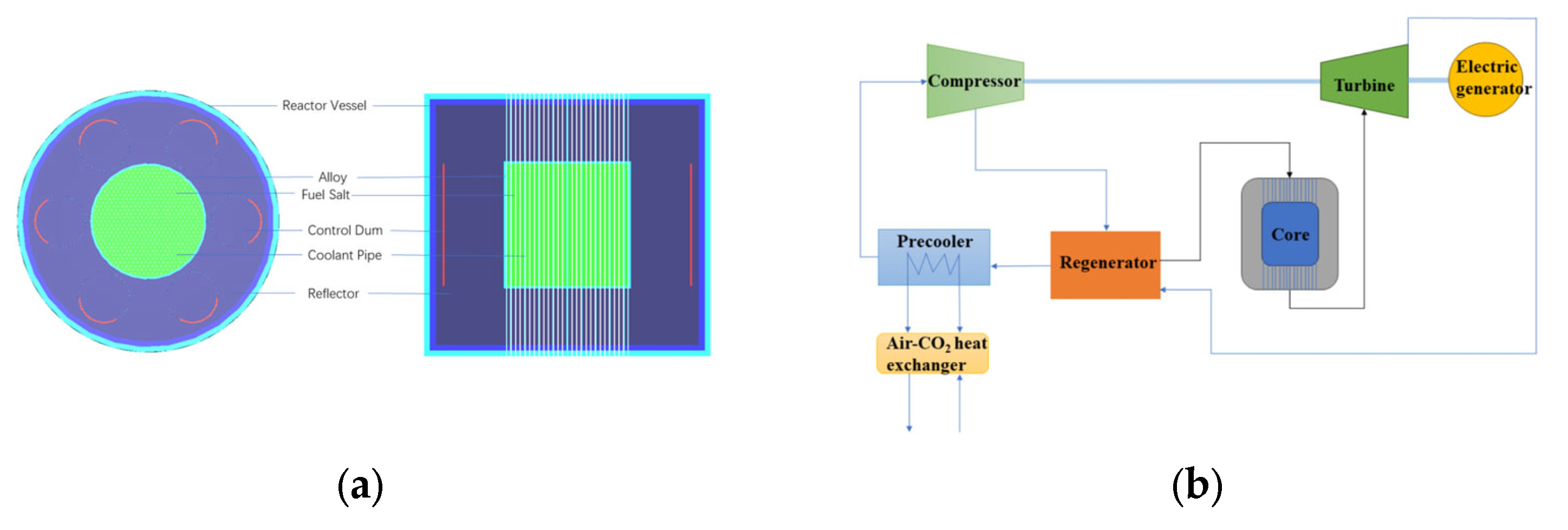
2.1. General Description of sm-MCFR

To achieve high core safety performance and reduce core maintenance, the structure, fuel, cooling system, and power generation system of the sm-MCFR were selected based on the following design objectives:
  • Reactor power of 10 MW;
  • A core life of 20 years;
  • The size of the reactor body to meet rail or road transport conditions;
  • Small reactivity swing to minimize the complexity of the control system arrangement;
  • Modular design: simplify the structure, reduce safety risks, and lower costs.
The following issues need to be addressed in the conceptual design phase of the sm-MCFR:
  • A reasonable core structure is proposed, which can satisfy the characteristics of small and transportable, long refueling cycle, and inherent safety;
  • Due to the limited reactor space, controlling residual reactivity during the long refueling period is a key issue;
  • To demonstrate the inherent safety of the sm-MCFR.
In a fused salt fast reactor, fluorine or chlorine salt is typically utilized as the fuel carrier salt. In this design, chlorine salt is utilized as the fuel carrier salt. The solubility of heavy metal is higher in chlorine salts than in fluorine salts. With the same volume, the chloride fast reactor has a greater capacity for loading heavy metals. In other words, the chloride salt reactor is smaller than the fluoride salt reactor with the same fuel load. The lower melting point of chlorine salt mitigates the risk of salt solidification during operation. In addition, chlorine salt has a large expansion coefficient, which increases negative feedback of the core temperature and thus improves the inherent safety of the core. On account of these distinctive attributes, the chloride reactor has unique miniaturization advantages. NaCl salt has been generally used as a carrier salt in the majority of chlorine salt fast reactors, including well-known examples such as Moltex and REBUS-3700 [25]. This broad application has resulted in a substantial accumulation of technical experience, facilitating its comprehensive study. Considering all factors, the core optimization design analysis in this study will use NaCl as the fuel carrier salt.
The fuel salt composition chosen for this study is 55 mol% NaCl + 45 mol% UCl3 [26]. The small modular chlorine salt fast reactor requires a safe operational temperature range to ensure normal operation and transient safety under accident conditions. For the NaCl and UCl3 system at this molar ratio, the liquid-phase line temperature is 600 °C according to the two-phase diagram of the fuel salt [27]. With a 50 °C safety margin in mind, the core temperature is set at 650 °C. There is a sufficient safety margin between the reactor operating temperature and the boiling point (1400 °C). As a result, 650 °C is thought to be sufficient for the reactor to operate safely. Fuel salt has a density of 3.6 g·cm−3 at 650 °C.
As a kind of small fast reactor, a small modular chlorine salt fast reactor has a high neutron leakage rate. To improve the neutron economy of the core, it is particularly important to use a neutron reflector with excellent performance [28]. The selection of the reflector layer material is dependent on two primary factors to fulfill the reflector layer optimization goal. Firstly, the material should possess high neutron reflectivity, thereby enabling the reflection of leaked neutrons back to the core. This is instrumental in maintaining core criticality while simultaneously reducing core size. Secondly, the material should exhibit good power spreading capability outside the active zone, which is conducive to a stable radial power distribution within the core and enhances fuel utilization. Following research, BeO, graphite, ZrO2, and SiC were selected as the reflective layer materials. To lower the core size and fuel loading, the core lifetime, core neutron energy spectrum, and core power distribution are evaluated in this article. The details are described in Section 3.4.
Molybdenum alloys are commonly used as structural materials in fast reactors. TZM alloy is a superalloy commonly used in molybdenum base alloy [29]. Due to its exceptional qualities, such as its high melting point, high strength, resistance to corrosion, and advantageous high-temperature mechanical characteristics, it has been widely used in the industry. The TZM alloy has been employed as a shielding material in the Russian MOSART reactor [30]. As a result, the reactor vessel and coolant piping in this design were made of TZM alloy. The composition of TZM alloy is listed in Table 1.
In previous designs of chlorine salt fast reactors, chlorine salt has fulfilled a dual role, serving both as a fuel salt to produce energy and as a coolant to expel heat from the core. However, this approach has led to various issues, including material corrosion, excessive fuel loading, and other associated challenges. The process of fuel salt moving from the core to the heat exchanger poses a risk of radioactive material leakage. Furthermore, the flow of fuel salt exacerbates pump corrosion, necessitating the deployment of molten salt pumps with better corrosion resistance. The small modular fast reactor is designed to eliminate these concerns. In the present design, the chlorine salt serves solely as a fuel salt, and not as a coolant. Instead, gas is used as a coolant. A specific quantity of gas is pumped into the core to remove heat from the core and transport it to the secondary loop. The core safety hazards are reduced by this design strategy. The demands for miniaturization and modularization are satisfied by greatly simplifying the reactor construction.
Currently, three gases are frequently utilized as reactor coolants: nitrogen, helium, and supercritical carbon dioxide. Using nitrogen as a coolant can impact the reactor’s neutron efficiency because nitrogen has a significant thermal neutron absorption cross-section of roughly 1.9 barns. The thermal conductivity of nitrogen is low, only 0.025 W/(m·K) at normal temperature and pressure. However, the thermal conductivity of helium at room temperature is about 0.142 W/(m·K), which means the heat is swiftly transmitted out of the core. Due to its comparatively low molar mass and high specific volume, helium exhibits a large volume flow, which in turn requires larger equipment and pipe volume. Moreover, the high specific heat of helium at constant pressure increases cycle-specific work and complicates compression. In comparison to other process gases, supercritical carbon dioxide has a higher thermal efficiency due to its high density, low viscosity, and low compression coefficient. Because S-CO2 is easily compressed, employing it as a coolant can help reduce equipment size and compression power, which increases equipment compactness and frees up space. Supercritical carbon dioxide has a potential future in small reactors. Based on these advantages and the design principles of this study, S-CO2 was selected as the coolant. When S-CO2 is used as a coolant, the pressure difference between the fuel salt and S-CO2 could result in the coolant tube failing, which is a potential concern that places significant demands on the coolant tube material. In this design, TZM alloy with good performance is used as the coolant tube, which reduces the probability of potential risks caused by the direct use of S-CO2. S-CO2 is pumped into the core to transfer heat directly to the turbine for use, after which the Brayton cycle power generating system is linked.
For the reactor to operate steadily and safely, the reactor control system is a crucial component. The control rod control scheme, which would significantly increase the size of the core, is not taken into consideration in this design considering the miniaturization and modular layout of the core. Instead, the control drum control is used. The control drum is made up of a reflector layer and a portion of neutron absorber material coated on the surface. To control the core’s reactivity, the neutron absorber-coated side is spun towards or away from the core. It is easier to achieve a smaller and more compact layout of the core by placing the control drum inside the core reflection layer, which does not increase the dimension of the whole core.
In addition, when the control drum is facing inward, the reactor must be in a deep subcritical condition in order for the control drum to satisfy the reactivity control requirement [31]. Fast reactor stopping depths are typically required to be 0.037 in the cold state and 0.024 in the hot state. Since the design of this work is a fast reactor, the core stopping condition effective neutron multiplication coefficient keff is set to 0.976. While the control drum is faced outward, the system ought to have sufficient residual reactivity to operate at full power for more than 20 years. The control drum placement in the reflector layer is depicted in Figure 1. In the reflector layer, which has a height equal to that of the active zone of the core, six groups of identically constructed control drums are distributed uniformly. The control drum coating material is made of B4C with natural enrichment. To maximize core reactivity control, the control drum’s inner material is the same as the reflecting layer material. The outer cladding material utilized in this study consists of SiC, which has a thickness of 10 mm. In terms of the reactivity control value, this study will identify the ideal control drum size and other factors such as neutron absorber thickness and cladding angle. Detailed descriptions are given in Section 4.1.
The system layout of the 10 MW sm-MCFR’s design model is shown in Figure 1. The reactor core is constructed as a tank-like structure and incorporates supercritical carbon dioxide cooling channels fashioned from TZM alloy. The active zone of the core is uniformly distributed with S-CO2-coolant pipes 0.1 cm thick. The active zone of the reactor measures 62 cm in radius and 124 cm in height. Radial and axial reflective layers of 60 cm and 38 cm thickness are installed at the border of the active region. To lessen neutron leakage and damage to the reactor vessel wall, 5 cm thick B4C is installed between the reflector layer and the reactor vessel. The side reflector has six control drums symmetrically inserted into it. Table 2 displays the major reactor core parameters.

2.2. Calculation Tool

Standardized Computer Analyses for Licensing Evaluation (SCALE) 6.1 [32], which is a comprehensive simulation program developed by Oak Ridge National Laboratory for reactor safety analysis and design, was used in this study. The 89 computational modules offered in this tool are primarily employed for reactor physical analysis, radiation shielding, radioactivity source analysis, and sensitivity analysis, among others. The software’s graphical user interface enables accurate modeling and quick access to the required calculation information. The present investigation focuses on the CSAS6 and TRITON sequences of SCALE 6.1, where CSAS6 is used for criticality safety analysis, including relevant cross-section processing and criticality analysis, while TRITON is a multi-purpose control sequence that integrates neutron transport, burnup calculation, sensitivity, and uncertainty analysis. The calculations were based on the 238-group ENDF/B-VII library (V7-238). The calculation used more than three million particles, and the statistical error was less than 10−4.
In addition to SCALE 6.1, other tools and techniques also can be used to perform core physics calculations for molten salt reactors. The VTT Technical Research Center of Finland developed the Monte Carlo program Serpent to calculate burnup [33]. The burnup module of the Nuclear Fuel Cycle Simulation System (NFCSS) is capable of calculating actinides and fission products [34]. The transmutation trajectory analysis (TTA) method provides the possibility to calculate the sensitivity coefficient [35]. The Trajectory Period Folding Method is another innovative technique for the numerical study of fuel changes [36].

3. Core Design

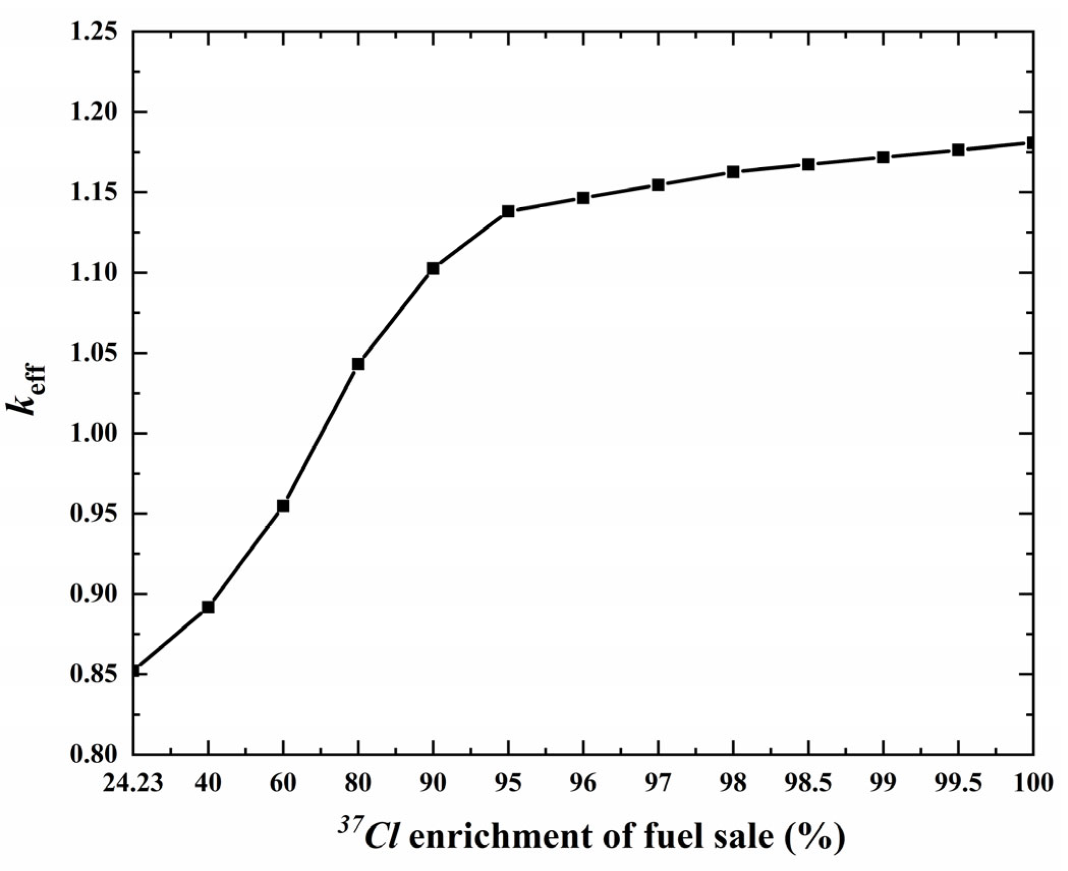
3.1. Enrichment of Chlorine-37

Chlorine in its natural state comprises two isotopes, namely 37Cl and 35Cl, which have relative profusions of 24.23% and 75.77%. Notably, 35Cl shows an absorption cross-section 102 times greater than that of 37Cl. The 35Cl produces two hazardous nuclides within nuclear reactors, namely S and 36Cl. As S causes corrosion in structural materials and 36Cl emits a higher intensity of beta radiation, these nuclides pose serious risks to the atmosphere and the reactor infrastructure in the case of leakage [37]. To maximize the safety of the core, the enrichment of 37Cl in the fuel salt is optimized in this part, making 37Cl the dominant isotope. This reduces the harmful absorption of 35Cl to neutrons and the generation of harmful products and improves the safety performance of the core.
Figure 2 shows the impact of various 37Cl enrichments in the fuel salt on the core keff. When 37Cl enrichment is only 24.23 percent, the core cannot achieve criticality. As the 37Cl enrichment increases, the keff gradually increases. However, when the 37Cl enrichment in the fuel salt reaches 98%, the increase in 37Cl enrichment keff is not readily obvious. The 35Cl level in the carrier salt falls as the 37Cl enrichment grows. This lowers the rate at which 35Cl absorbs neutrons. This results in increased utilization of neutrons by fission nuclides in fuel salts, increasing the keff. The effect of increasing the 37Cl enrichment on the keff is not immediately obvious when the 37Cl enrichment is greater than 98%. This is because the 35Cl content is low enough that its absorption of neutrons is small. Therefore, a 98% enrichment of 37Cl was used in this design.

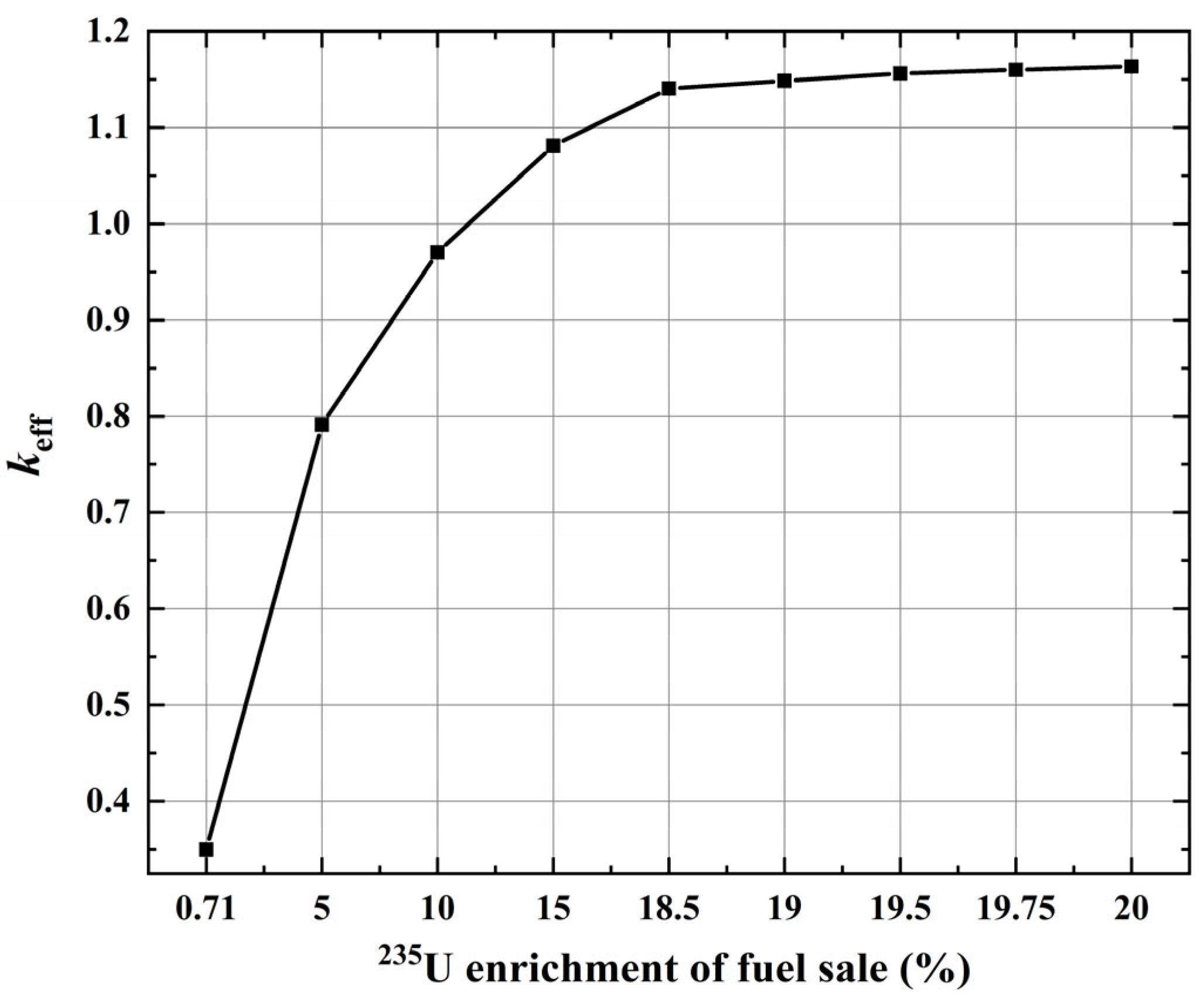
3.2. Enrichment of Uranium-235

Of natural uranium, 99.28% is 238U, while 0.71% is 235U. Small modular chlorine fast reactors, in contrast to big chlorine fast reactors, mainly take reactor criticality into account instead of reactor multiplication or transmutation. More 235U is needed to keep the reactor criticality in order for the reactor to operate for 20 years without refueling. The initial keff of the reactor grows with the increase in 235U enrichment, as depicted in Figure 3. Reactor refueling cycles can be prolonged and reactor size can be decreased by increasing the 235U enrichment in natural uranium. However, excessive uranium enrichment can be expensive and could lead to issues with nuclear proliferation. Thus, a decision must be made between the expense of enrichment and core size. Low-enrichment uranium is defined by the International Atomic Energy Agency as having less than 20% 235U [38]. Uranium with a 19.75% enrichment was used in this research to minimize the expense of uranium enrichment and prevent nuclear proliferation.

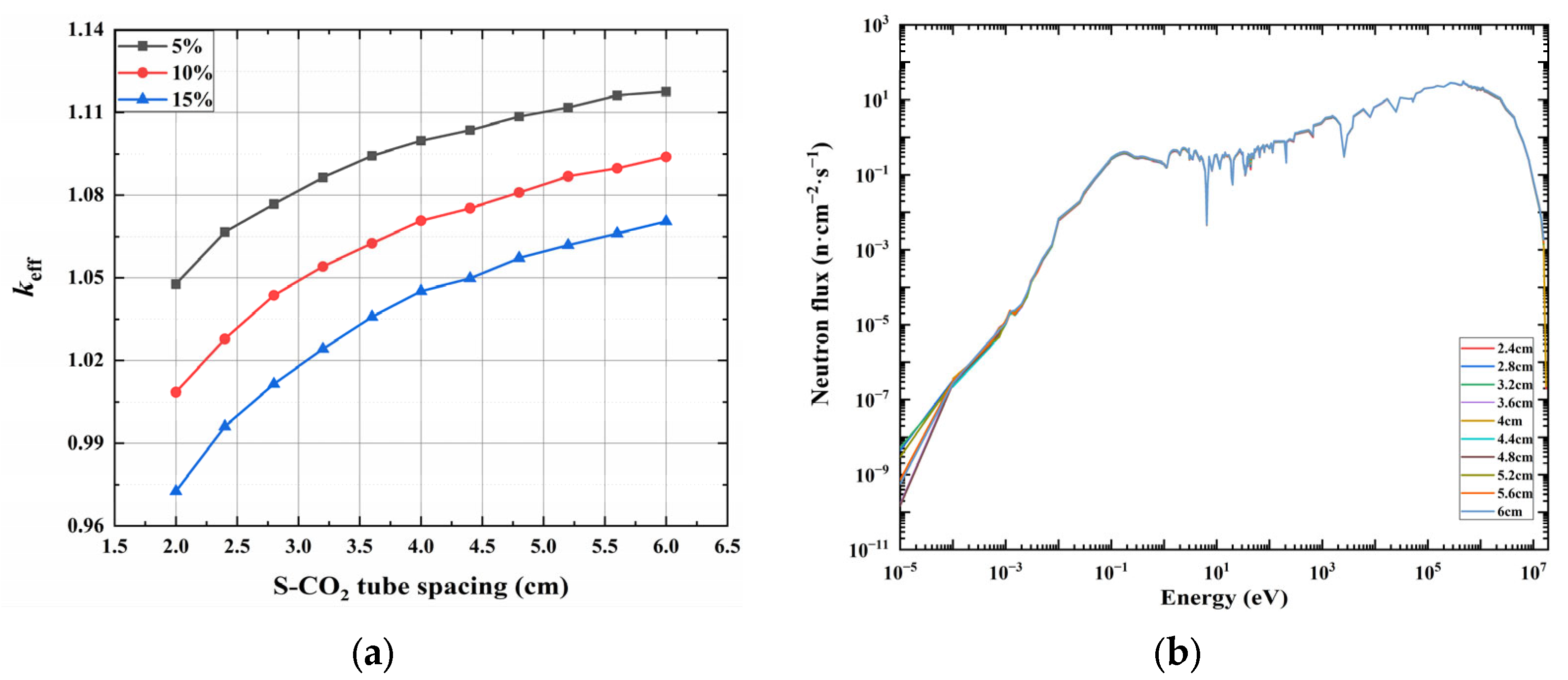
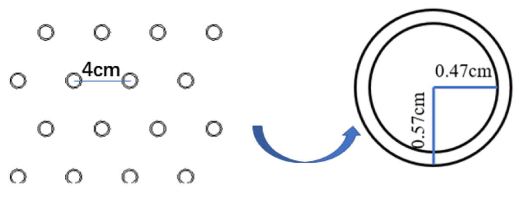
3.3. Coolant Pipe Size

The S-CO2 gas-cooled core is utilized in this design, and the circular gas coolant channels are uniformly distributed in the active zone of the core in the form of hexagons. Considering the compatibility of coolant, fuel salt, and piping, TZM alloy with a thickness of 0.1 cm is used as the coolant piping material. The coolant pipe must be appropriately set up to remove heat from the core effectively. The volume ratio of coolant to fuel and the distance between various coolant tubes are crucial to the core performance. In this section of the calculation, the length of the coolant tubes is not altered. Only the volume ratio of coolant to fuel and the tube spacing are changed. Under the condition of constant activity in the reactor core, the keff values for different tube spacings were calculated with Vcool/Vreactor ratios of 5%, 10%, and 15%. The results shown in Figure 4a demonstrate that the keff rises as tube spacing increases and rises as the coolant percentage decreases. Coolant percentages are kept constant by maintaining a fixed active zone size, and the number of S-CO2 tubes decreases with increasing tube spacing. As a result, the number of neutrons absorbed by the core’s coolant tubes decreases, increasing the initial reactivity. The decrease in coolant percentage directly increases the volume of core molten salt and fuel loading when the tube spacing remains constant, which improves the core’s initial reactivity. Figure 4b shows the neutron energy spectra at various tube spacings when Vcool/Vreactor is 5%. When the coolant percentage is constant, the tube diameter can be determined by determining the tube spacing. When the coolant tube spacing is changed, the tube diameter will follow suit. Additionally, there is just one and only one coolant tube diameter that corresponds to each tube spacing. As a result, when the coolant percentage remains constant, the coolant tube spacing reduces, the corresponding tube diameter lowers, and the number of coolant tubes increases. This causes the neutron absorption rate of the coolant tubes to increase, reducing the core neutron economy and softening the energy spectrum.
Considering the neutron performance of the sm-MCFR, a coolant volume share of 5% is considered to be the most appropriate choice. The quantity and dimensions of tubes depend on the spacing between the cooling tubes. The smaller the coolant tube spacing and the more tubes there are, the more neutrons will be absorbed. When the tube spacing is less than 4 cm, the number of tubes will exceed 600. This will make the neutron economy of the system worse. Additionally, the increase in the number of tubes has an impact on the natural convection of the fuel, which prevents the radial power distribution in the core from flattening out. The S-CO2 tube radius increases with the increase in tube spacing when Vcool/Vreactor is determined. When the tube spacing is 4 cm, the tube radius is 0.47 cm. The existing studies on heat transfer in S-CO2 flow and the available heat transfer data are mainly focused on small-diameter tubes (din < 1 cm). However, when the tube spacing increases to 4.4 cm, the tube radius expands to 0.52 cm and the diameter to 1.04 cm. In addition, the S-CO2 heat transfer is also somewhat influenced by the tube diameter. It is generally believed that the smaller the tube diameter, the better the heat transfer. With other operating conditions staying constant, increasing tube diameter will increase the degree of heat transfer deterioration. As a result, from the point of view of neutron performance, power distribution and heat transfer performance, the tube spacing value is set to 4 cm and the coolant channel radius is changed to 0.47 cm, as pictured in Figure 5.

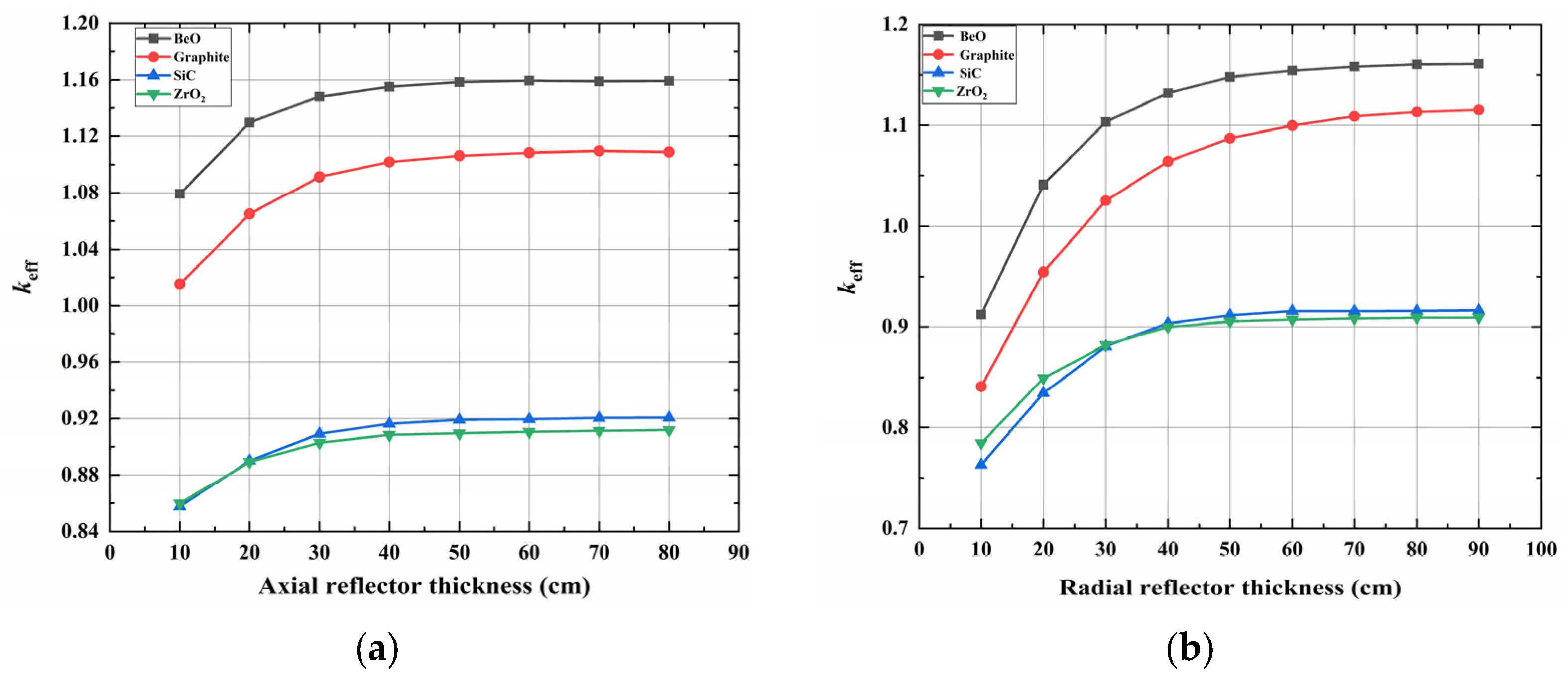
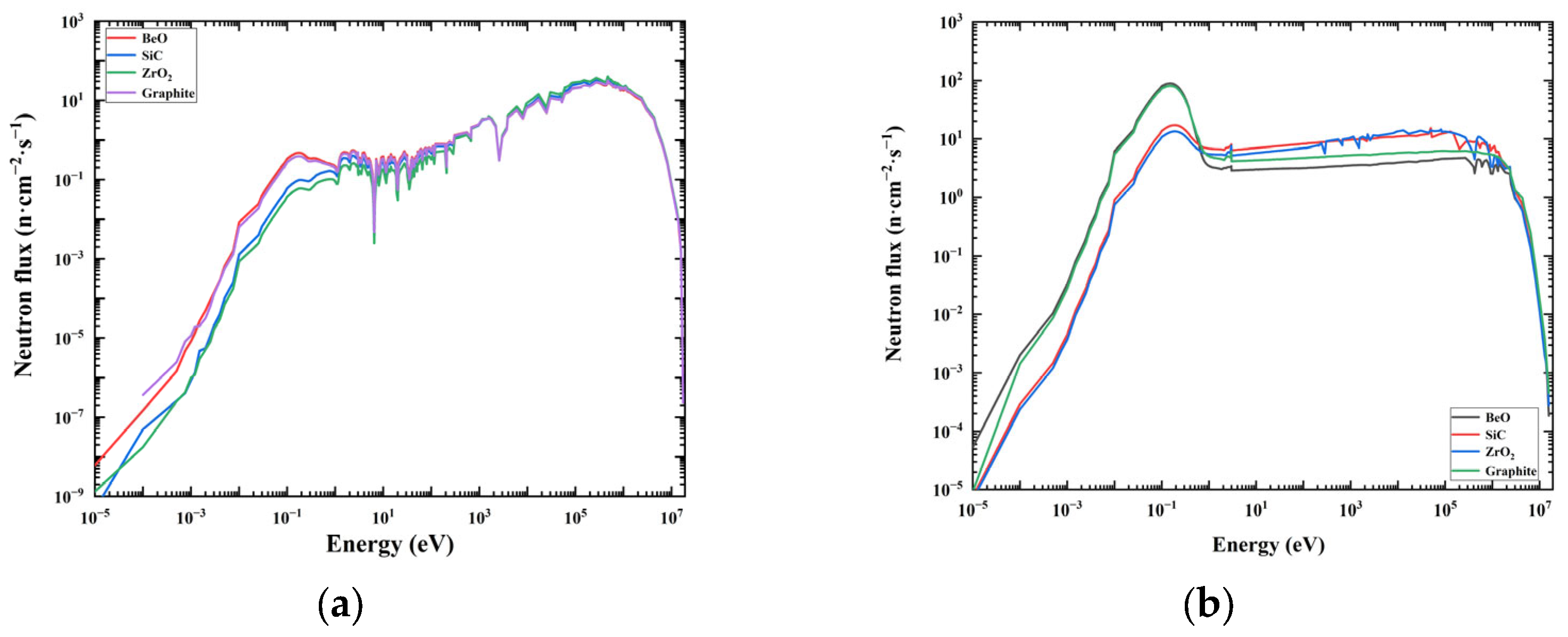
3.4. Materials and Thickness of the Reflector
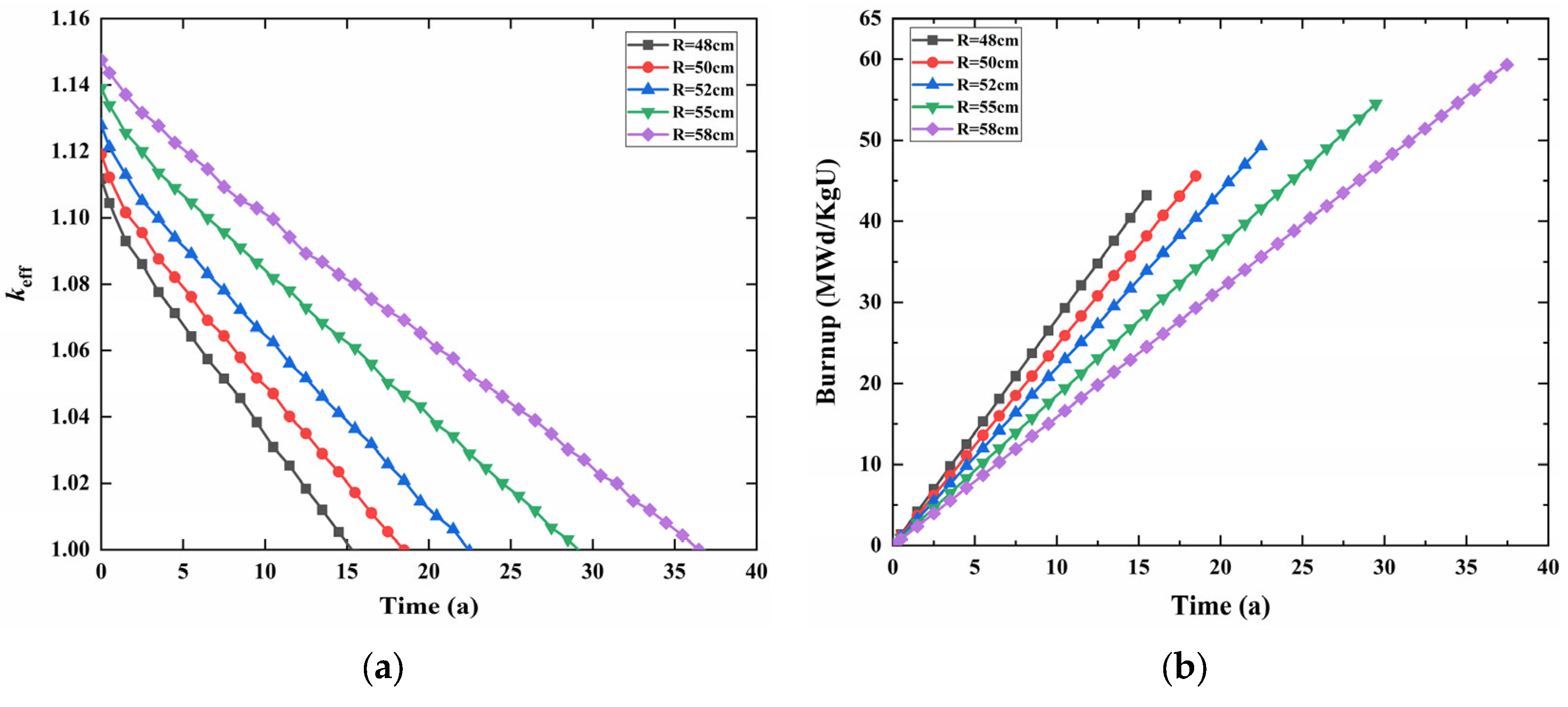
The influence of different reflector materials on the physical properties of neutrons in the core is discussed in this section. The variation curves of core reactivity for different axial and radial thicknesses of the four reflective layers, BeO, graphite, SiC, and ZrO2, are illustrated in Figure 6a,b, respectively. When SiC and ZrO2 are employed as reflector layers, the neutron leakage is much higher and the initial reactivity of the core is less than 1. Under these two materials, the reactor cannot be in a critical state, which obviously violates the design objectives. BeO has a shorter diffusion length than graphite, reducing core volume while leaving the initial residual reactivity unchanged. Compared with graphite, BeO has a bigger macroscopic scattering cross-section and a better neutron reflection effect. Therefore, BeO has a great advantage in maintaining core reactivity. In this design, BeO is selected as the reflective layer, which helps to reduce the size of the core while maintaining the critical state of the core. At this point, the core keff is maximum and the neutron economy is better.
The energy spectra of the active and reflective regions of the core at the beginning of the lifetime when the axial and radial reflector thicknesses are both 50 cm at the initial conditions are shown in Figure 7. The neutron ratio of each energy group in the core’s active region and the neutron energy spectrum are essentially unchanged when using these four reflector layer materials. There are certain changes in the neutron energy spectrum of the reflector region, which is closely related to the reflector material. For BeO and graphite, the content of oxygen and carbon nuclides per unit volume is higher than that of other materials, resulting in more fast neutrons being moderated and having a higher neutron fraction in the low-energy region. When BeO is used as the reflector, the thermal neutrons in the reflector increase obviously, and the neutron energy spectrum in the reflector is a thermal spectrum. However, its active region energy spectrum is still a fast neutron spectrum, which meets the design objective.
With the increase in the reflector thickness, the neutron leakage rate decreases, and the initial reactivity and burnup of the core increase. Therefore, designing a reasonable thickness is one of the key factors for maximizing the value of the reflector layer. The increase in keff slows down when the reflector layer’s radial and axial thicknesses reach 50 cm and 60 cm, respectively. The reason for this is that if the reflector layer’s thickness surpasses the distance at which neutrons diffuse inside it, additional thickness increases will have less impact on neutron diffusion, and the change in keff will be less obvious. At this point, increasing the reflector thickness will not only fail to improve neutron economy, but also result in an undesired increase in reactor size, which is in conflict with the goal of miniaturization. Therefore, to reduce the core size and fuel loading, BeO is employed as the reflector layer material. The radial and axial reflector thicknesses are set to 60 cm and 50 cm, respectively.

3.5. Core Size

Small modular reactors must be transportable. When using special transportation, the reactor length should be less than 15.5 m, and the diameter should be less than 3.88 m. So, the core size needs to be studied. As can be seen in Section 3.4, the reflection layer has an axial thickness of 50 cm and a radial thickness of 60 cm. At this time, the height-to-diameter ratio of the active zone is set to 1:1, and the radius of the core is varied to examine the neutron physical characteristics of the core at various radii. The changes in burnup and initial residual reactivity over time for various core active zone radii are depicted in Figure 8. As the radius increases, so does the lifetime and burnup of the reactor. This is because expanding the radius of the active zone increases fuel loading and hardens the neutron spectrum of the core. The extension of the core lifetime is accompanied by an escalating consumption of 235U. However, under constant power, the enlargement of active zone volume causes a reduction in core power density, which can lead to a decrease in 235U utilization. To meet the design objectives, the core volume is reduced as much as possible while still allowing the reactor to work at full capacity for 20 years. With a height-to-diameter ratio of 1:1, the active zone radius is set at 52 cm and the height at 104 cm, when the core is the ideal design. This arrangement has a core life of 22.4 years and a fuel consumption of 49.2 MWd/kgU, which results in favorable neutron economics.

4. Physical Characteristic Analysis Based on the sm-MCFR

4.1. Control Solution Design

After completing the overall core design, the reactor control system needs to be designed by the design guidelines. The core radial structures with absorbent cladding angles of 60° and 180° where the control drum is faced inside or outward are shown in Figure 9. First, the control drum radius was set to 24 cm, the SiC cladding was 0.1 cm thick, and naturally enriched B4C served as the coated neutron absorber. The variation in core reactivity values corresponding to various absorber cladding angles (60–180°) is investigated with a fixed B4C thickness of 1 cm, as shown in Figure 10. When the control drum is turned out and in, the keff slightly decreases as the B4C wrap angle increases. The value of the control drum exhibits a pattern of first increasing and then decreasing, peaking at 120°. The increase in the B4C control drum tension angle leads to two opposing effects. Firstly, the B4C material volume ratio increases, which enhances the control capabilities of the control drum and increases the control value. Secondly, the increase in the B4C material volume ratio results in more core neutrons being absorbed by B4C, leading to a fall in reactivity. Specifically, the former effect dominates in the 60–120° range, while the latter effect dominates in the 120–180° range. Considering the reactivity control requirements of the reactor, 120° when the drum value is larger is selected as the wrap angle size of the B4C absorber for this design.
In addition, optimizing the thickness of the B4C absorber in the control drum is also necessary. In this section, the impact of different B4C absorber thicknesses on the value of the drum is examined. As shown in Figure 11, the control drum value increases with B4C thickness at a constant tension angle. With an increase in B4C thickness in the control drum, a larger amount of material is available to absorb neutrons in the core. Therefore, the increase in the control drum value is accompanied by a corresponding reactivity penalty, resulting in a decrease in the initial residual reactivity of the core. Conversely, a decrease in B4C thickness leads to a decrease in the control drum value and an increase in the remaining core reactivity. As the thickness of the absorber continues to increase, the increment in the control drum value becomes slower. The specific value of the neutron absorber thickness is mainly considered in relation to whether the stopping depth meets the design when a single control drum fails. After careful consideration, B4C with a thickness of 1.5 cm and a cladding angle of 120° was chosen as the ideal neutron absorber for the control drum.
The change in core reactivity for a single control drum angle shift is also analyzed in this part. The angle of rotation is defined as 0° when the control drum is turned inside and 180° when it is turned outward. To calculate changes in core reactivity, the angular position of five control drums is held constant at 0°, while another control drum is rotated counterclockwise.
Based on the analysis presented in Figure 12, it is obvious the effective neutron multiplication coefficient keff presents a non-linear relationship with the movement angle of the control drums. Specifically, the core reactivity increases as the turning angle increases. The reactivity changes the most when rotating from 80° to 90°, which is about 0.00619. In contrast, the drum value is lowest when the control drum is turned at 0°.

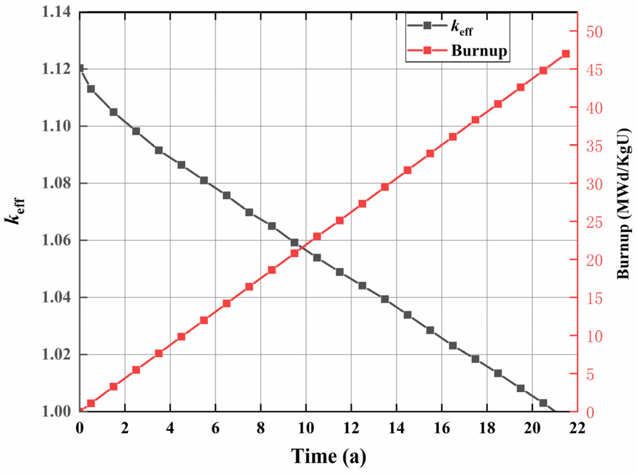
4.2. Burnup Calculation

There is a close relationship between the reactor operating cycle and the control drums. The core lifetime and burnup over time for all six control drums rotated to the maximum outward position are plotted in Figure 13. The core burnup depth is seen to gradually rise with reactor operating time. However, the control drums located in the reflector layer also absorb neutrons. This reduces the number of neutrons reflected back to the core, decreasing the reactor’s operational lifetime. This design scenario has a core life of 21 years and a fuel consumption of 47 MWd/kgU, which meets the design goal of 20 years of sm-MCFR operation.

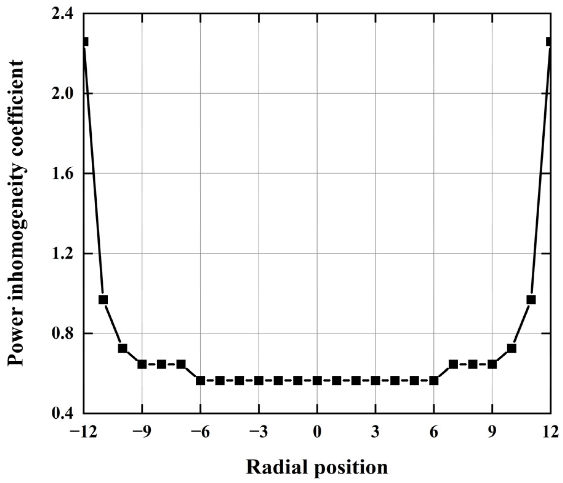
4.3. Power Distribution

The power distribution is mainly influenced by the neutron flux and energy spectrum distribution of the core. The power distribution differs in different parts of the core due to variations in the neutron flux and neutron energy spectrum. As shown in Figure 14, the inhomogeneity coefficient of radial power distribution across the core diameter indicates a pronounced symmetry in the distribution. The ratio of the fuel power density at different locations to the average power density of the core is known as the power inhomogeneity coefficient. Near the reflector, the power density is higher and the fuel power distribution coefficient is larger. As the BeO reflector outside the core plays a moderating role at the same time, the proportion of thermal neutrons near the reflector increases. Because the neutron capture cross-section of 135Xe is below one barn in fast reactors, the effect of 135Xe is negligible. Therefore, there is a small chance that anomalous power density will appear inside the reactor [39]. In addition, because 235U thermal fission cross-sections are larger than 235U fast fission cross-sections, the average power of the fuel at the periphery of the core is greater than that in the core, which results in the warping of the power distribution. In general, the power distribution is uniform and reasonable.

4.4. Reactivity Coefficient

Changes in core temperature during reactor operation will cause variations in reactivity, making the temperature reactivity coefficient (TRC) a crucial measure of core safety. To ensure safe operation throughout the lifetime of the reactor, the core should have a negative reactivity effect that can help mitigate any sudden temperature increases that may occur. In order to preserve core operational stability and lower potential safety risks, negative temperature coefficients are essential for nuclear safety. TRC is generally composed of the fuel temperature coefficient (FTC), coolant temperature coefficient (CTC), moderator temperature coefficient (MTC), and void coefficient of reactivity (VCR). Because there is no moderator in the active zone and the boiling point of molten salt is high, the moderator temperature effect and the cavitation effect brought on by boiling molten salt are not factors that need to be taken into account in this design. The TRC is primarily determined by the FTC and CTC. The fuel Doppler effect and fuel density effect are the key factors affecting the fuel temperature coefficient, which is negative as indicated in Table 3. On the one hand, the density of fissionable nuclides in the fission area decreases as temperature rises, which causes the macroscopic cross-section of the fissionable nuclide to decrease. On the other hand, the increase in temperature broadens the Doppler resonance peak and increases the resonance absorption of the nuclide, which is influenced by the resonance absorption of the nuclide. So, keff drops, creating a negative temperature effect. Although the CTC is positive throughout the sm-MCFR operation, its magnitude is minimal, and the TRC is always negative, ensuring the intrinsic safety of the core.

5. Conclusions

Through the integration of molten salt reactor and gas-cooled reactor technologies, a 10 MW gas-cooled small modular molten salt reactor scheme with a lifespan of more than 20 years is proposed in this study. The neutronic design, optimization, and evaluation analysis of the core scheme were conducted. The reactor core modeling was performed using the SCALE 6.1 program. Detailed investigations were conducted into the effects of the core parameters on the effective multiplication factor and reactor lifetime. These core parameters include 37Cl enrichment, 235U enrichment, coolant ratio, coolant tube spacing, reflective layer thickness, and active zone radius. A comprehensive investigation of the reactivity control system based on the control drum has been provided. Specifically, the impact of parameters such as the neutron absorber envelope angle and B4C thickness on the control drum’s value was examined.
Following a comprehensive evaluation of all relevant factors, the final core features for this study were established as follows: fuel salt enriched with 37Cl at a rate of 98%, 235U enriched to 19.75%, coolant pipe with an inner radius of 0.47 cm and outer radius of 0.57 cm, pipe spacing set at 4 cm, active zone radius of 52 cm, a height-to-diameter ratio of 1:1, and reflective layer thickness of 60 cm and 50 cm for radial and axial directions, respectively. With such core geometry design parameters, the reactor can meet the design needs of modularization and miniaturization of the core. The neutron absorber for the control drum consists of B4C, with a thickness of 1.5 cm and an envelope angle of 120°, meeting the necessary reactivity control requirements of the core. The optimized sm-MCFR parameters are summarized in Table 4.
Finally, the characteristics of neutrons in the core were examined. An initial feasibility study of the reactor idea design was conducted. The findings indicate that the reactor can attain a critical value within a specific fuel composition. The core can operate at full power for 21 years. Further, the control drum arrangement meets the full-life reactivity control needs of the reactor.

Author Contributions

Conceptualization, M.P.; methodology, M.P.; software, Y.D.; writing—original draft preparation, M.P.; writing—review and editing, M.P., Y.L. and Y.Z.; supervision and project administration, M.P., Y.L. and Y.Z.; funding acquisition, Y.L. All authors have read and agreed to the published version of the manuscript.

Funding

This research was funded by the National Natural Science Foundation of China grant number 12205362.

Data Availability Statement

The data presented in this study are available on request from the corresponding author. The data are not publicly available due to privacy.

Conflicts of Interest

The authors declare no conflict of interest.

References

  1. Ingersoll, D.T. Deliberately small reactors and the second nuclear era. Prog. Nucl. Energy 2009, 51, 589–603. [Google Scholar] [CrossRef]
  2. Sabharwall, P.; Mckellar, M.; Kim, E.S.; Patterson, M. Small Modular Molten Salt Reactor (SM-MSR). In Proceedings of the ASME 2011 Small Modular Reactors Symposium, ASME 2011 Small Modular Reactors Symposium, Washington, DC, USA, 28–30 September 2011; pp. 31–39. [Google Scholar]
  3. Carelli, M.D.; Garrone, P.; Locatelli, G.; Mancini, M.; Mycoff, C.; Trucco, P.; Ricotti, M.E. Economic features of integral, modular, small-to-medium size reactors. Prog. Nucl. Energy 2010, 52, 403–414. [Google Scholar] [CrossRef]
  4. Todreas, N.E. Small Modular Reactors (SMRs) for Producing Nuclear Energy: An Introduction; Woodhead Publishing: Sawston, UK, 2015. [Google Scholar]
  5. Kuznetsov, V. Iaea activities for innovative small and medium sized reactors (SMRs). Prog. Nucl. Energy 2005, 47, 61–73. [Google Scholar] [CrossRef]
  6. Zhu, D.; Xiang, Q.; Zhang, M.; Deng, C.; Deng, J.; Jiang, G.; Yu, H. Evaluation of in-vessel corium retention margin for small modular reactor ACP100. Ann. Nucl. Energy 2016, 94, 684–690. [Google Scholar] [CrossRef]
  7. Odeh, F.Y.; Yang, W.S. Core design optimization and analysis of the Purdue Novel Modular Reactor (NMR-50). Ann. Nucl. Energy 2016, 94, 288–299. [Google Scholar] [CrossRef] [Green Version]
  8. Bae, S.J.; Lee, J.; Ahn, Y.; Lee, J.I. Preliminary studies of compact Brayton cycle performance for Small Modular High Temperature Gas-cooled Reactor system. Ann. Nucl. Energy 2015, 75, 11–19. [Google Scholar] [CrossRef]
  9. Shin, Y.-H.; Choi, S.; Cho, J.; Kim, J.H.; Hwang, I.S. Advanced passive design of small modular reactor cooled by heavy liquid metal natural circulation. Prog. Nucl. Energy 2015, 83, 433–442. [Google Scholar] [CrossRef]
  10. Chen, H.; Chen, Z.; Chen, C.; Zhang, X.; Zhang, H.; Zhao, P.; Shi, K.; Li, S.; Feng, J.; Zeng, Q. Conceptual design of a small modular natural circulation lead cooled fast reactor SNCLFR-100. Int. J. Hydrogen Energy 2016, 41, 7158–7168. [Google Scholar] [CrossRef]
  11. El-Genk, M.S.; Palomino, L.M. SLIMM-Scalable LIquid Metal cooled small Modular Reactor: Preliminary design and performance analyses. Prog. Nucl. Energy 2015, 85, 56–70. [Google Scholar] [CrossRef]
  12. Greene, S.R.; Gehin, J.; Holcomb, D.E.; Carbajo, J.J.; Ilas, D.; Cisneros, A.T.; Varma, V.K.; Corwin, W.R.; Wilson, D.F.; Yoder, G.; et al. Pre-Conceptual Design of a Fluoride-Salt-Cooled Small Modular Advanced High Temperature Reactor (SmAHTR); Oak Ridge National Laboratory: Oak Ridge, TN, USA, 2010. [Google Scholar]
  13. Pioro, I.L. 2—Introduction: Generation IV International Forum. In Handbook of Generation IV Nuclear Reactors; Pioro, I.L., Ed.; Woodhead Publishing: Sawston, UK, 2016; pp. 37–54. [Google Scholar] [CrossRef]
  14. Yu, S.-H.; Liu, Y.-F.; Yang, P.; Ji, R.-M.; Zhu, G.-F.; Zhou, B.; Kang, X.-Z.; Yan, R.; Zou, Y.; Dai, Y. Neutronics analysis for MSR cell with different fuel salt channel geometries. Nucl. Sci. Tech. 2021, 32, 9. [Google Scholar] [CrossRef]
  15. Ignatiev, V.; Feynberg, O.; Merzlyakov, A.; Surenkov, A.; Zagnitko, A.; Afonichkin, V.; Bovet, A.; Khokhlov, V.; Subbotin, V.; Fazilov, R.; et al. Progress in development of MOSART concept with Th support. In Proceedings of the Conference: ICAPP’12: 2012 International Congress on Advances in Nuclear Power Plants, Chicago, IL, USA, 24–28 June 2012. [Google Scholar]
  16. Furukawa, K.; Arakawa, K.; Erbay, L.B.; Ito, Y.; Kato, Y.; Kiyavitskaya, H.; Lecocq, A.; Mitachi, K.; Moir, R.; Numata, H.; et al. A road map for the realization of global-scale thorium breeding fuel cycle by single molten-fluoride flow. Energy Convers. Manag. 2008, 49, 1832–1848. [Google Scholar] [CrossRef]
  17. Fiorina, C.; Aufiero, M.; Cammi, A.; Franceschini, F.; Krepel, J.; Luzzi, L.; Mikityuk, K.; Ricotti, M.E. Investigation of the MSFR core physics and fuel cycle characteristics. Prog. Nucl. Energy 2013, 68, 153–168. [Google Scholar] [CrossRef]
  18. Gehin, J.C.; Holcomb, D.E.; Flanagan, G.F.; Patton, B.W.; Howard, R.L.; Harrison, T.J. Fast Spectrum Molten Salt Reactor Options; ORNL/TM-2011/105; ORNL: Oak Ridge, TN, USA, 2011. [Google Scholar]
  19. USDOE. A Technology Roadmap for Generation IV Nuclear Energy Systems. In Nuclear Energy Research Advisory Committee and the Generation IV International Forum; USDOE Office of Nuclear Energy; Science and Technology (NE): Washington, DC, USA, 2002. [Google Scholar]
  20. Pope, M.A. Reactor physics design of supercritical CO₂-cooled fast reactors. Master Thesis, Institute of Technology, Cambridge, MA, USA, 2004. [Google Scholar]
  21. Dostál, V. A Supercritical Carbon Dioxide Cycle for Next Generation Nuclear Reactors. Ph.D. Thesis, Institute of Technology, Cambridge, MA, USA, 2004. [Google Scholar]
  22. Yu, H.; Hartanto, D.; Moon, J.; Kim, Y. A Conceptual Study of a Supercritical CO2-Cooled Micro Modular Reactor. Energies 2015, 8, 13938–13952. [Google Scholar] [CrossRef] [Green Version]
  23. Kim, Y.; Hartanto, D.; Yu, H. Neutronics optimization and characterization of a long-life SCO2-cooled micro modular reactor. Int. J. Energ Res. 2017, 41, 976–984. [Google Scholar] [CrossRef]
  24. Li, C.Y.; Wei, W.S.; Bin, X.W. Features and Application Analysis of the Small Modular Reactors. Nucl. Electron. Detect. Technol. 2014, 34, 6. [Google Scholar]
  25. Scott, I.R. Stable Salt Reactor Design Concept. In Proceedings of the Thorium Energy Conference, Mumbai, India, 12–15 October 2015. [Google Scholar]
  26. Desyatnik, V.N.; Katyshev, S.F.; Raspopin, S.P.; Chervinskii, Y.F. Density, Surface-Tension, and Viscosity of Uranium Trichloride Sodium Chloride Melts. Sov At. Energy 1975, 39, 649–651. [Google Scholar] [CrossRef]
  27. Mourogov, A.; Bokov, P.M. Potentialities of the fast spectrum molten salt reactor concept: REBUS-3700. Energy Convers. Manag. 2006, 47, 2761–2771. [Google Scholar] [CrossRef]
  28. Wallenius, J.; Qvist, S.; Mickus, I.; Bortot, S.; Szakalos, P.; Ejenstam, J. Design of SEALER, a very small lead-cooled reactor for commercial power production in off-grid applications. Nucl. Eng. Des. 2018, 338, 23–33. [Google Scholar] [CrossRef]
  29. El-Genk, M.S.; Tournier, J.-M. A review of refractory metal alloys and mechanically alloyed-oxide dispersion strengthened steels for space nuclear power systems. J. Nucl. Mater. 2005, 340, 93–112. [Google Scholar] [CrossRef]
  30. Ignatiev, V.; Surenkov, A. Alloys compatibility in molten salt fluorides: Kurchatov Institute related experience. J. Nucl. Mater. 2013, 441, 592–603. [Google Scholar] [CrossRef]
  31. Chen, R.K.; Seidl, M.; Wang, X. Core design optimization of small modular dual fluid reactor based on NSGA-III in the aspect of reactor physics. Ann. Nucl. Energy 2022, 174, 109194. [Google Scholar] [CrossRef]
  32. Bowman, S. SCALE 6: Comprehensive Nuclear Safety Analysis Code System. Nucl. Technol. 2011, 174, 126–148. [Google Scholar] [CrossRef]
  33. Ferraro, D.; García, M.; Valtavirta, V.; Imke, U.; Tuominen, R.; Leppänen, J.; Sanchez-Espinoza, V. Serpent/SUBCHANFLOW pin-by-pin coupled transient calculations for the SPERT-IIIE hot full power tests. Ann. Nucl. Energy 2020, 142, 107387. [Google Scholar] [CrossRef]
  34. Oettingen, M. Assessment of the Radiotoxicity of Spent Nuclear Fuel from a Fleet of PWR Reactors. Energies 2021, 14, 3094. [Google Scholar] [CrossRef]
  35. Cetnar, J.; Stanisz, P.; Oettingen, M. Linear Chain Method for Numerical Modelling of Burnup Systems. Energies 2021, 14, 1520. [Google Scholar] [CrossRef]
  36. Stanisz, P.; Oettingen, M.; Cetnar, J. Development of a Trajectory Period Folding Method for Burnup Calculations. Energies 2022, 15, 2245. [Google Scholar] [CrossRef]
  37. He, L.-Y.; Li, G.-C.; Xia, S.-P.; Chen, J.-G.; Zou, Y.; Liu, G.-M. Effect of 37Cl enrichment on neutrons in a molten chloride salt fast reactor. Nucl. Sci. Tech. 2020, 31, 27. [Google Scholar] [CrossRef]
  38. IAEA. IAEA Safeguards Glossary; International Atomic Energy Agency: Vienna, Austria, 2003. [Google Scholar]
  39. Oettingen, M.; Kim, J. Detection of Numerical Power Shift Anomalies in Burnup Modeling of a PWR Reactor. Sustainability 2023, 15, 3373. [Google Scholar] [CrossRef]
Figure 1. (a) Cross-sectional view of the sm-MCFR core layout; (b) the schematic diagram of sm-MCFR.
Energies 16 04862 g001
Figure 2. keff versus 37Cl enrichment of fuel salt.
Energies 16 04862 g002
Figure 3. keff versus 235U enrichment of fuel salt.
Energies 16 04862 g003
Figure 4. (a) The keff varies with the coolant tube spacing for different coolant volumes; (b) neutron spectrum at different tube spacings.
Energies 16 04862 g004
Figure 5. Coolant channel diagram.
Energies 16 04862 g005
Figure 6. (a) keff varies with axial reflector thickness; (b) keff varies with radial reflector thickness.
Energies 16 04862 g006
Figure 7. (a) Neutron energy spectra of active zone; (b) neutron energy spectra of reactor.
Energies 16 04862 g007
Figure 8. (a) keff versus time; (b) burnup versus time.
Energies 16 04862 g008
Figure 9. (a) Angle of 60° control drum inward radial structure; (b) angle of 60° control drum outward radial structure; (c) angle of 180° control drum inward radial structure; (d) angle of 180° control drum outward radial structure.
Energies 16 04862 g009
Figure 10. Influence of wrap angle of B4C on drum value.
Energies 16 04862 g010
Figure 11. Influence of wrap angle of B4C on drum value with different thicknesses.
Energies 16 04862 g011
Figure 12. Graph of individual control drum reactivity with rotation angle.
Energies 16 04862 g012
Figure 13. keff and burnup versus time.
Energies 16 04862 g013
Figure 14. Power distribution inhomogeneity coefficient under different radial positions.
Energies 16 04862 g014
Table 1. TZM alloy composition.
CompositionTiZrCSiFeNiNMo
Content/%0.50.080.01–0.040.0060.010.0050.003remainder
Table 2. Initial main parameters of sm-MCFR.
ParameterValue
Power (MW)10
Reactor radius/height (cm)132/220
Active zone radius/height (cm)62/124
Core fuelNaCl:UCl3 = 55:45
Fuel salt density (g·cm−3)3.6
Molten salt temperature (K)925
CoolantS-CO2
S-CO2 pipe materialTZM
S-CO2 pipe thickness (cm)0.10
Operating life (a)20
Table 3. Reactivity coefficient.
ParameterValue
CTC (pcm/K)0.136
FTC (pcm/K)−1.8959
TRC (pcm/K)−1.72
Table 4. Optimized parameters of sm-MCFR.
ParameterValue
Power (MW)10
Active zone radius/height (cm)52/104
Radial reflector thickness (cm)60
Axial reflector thickness (cm)50
Core fuelNaCl:UCl3 = 55:45
Fuel salt density (g·cm−3)3.6
Molten salt temperature (K)925
37Cl enrichment (%)98
235U enrichment (%)19.75
CoolantS-CO2
Coolant pipe materialTZM
Coolant pipe radius (cm)0.47
Coolant pipe thickness (cm)0.1
Coolant pipe outside radius (cm)0.57
Coolant pipe spacing (cm)4
Reactivity control systemControl drums
Control drum neutron absorber thickness (cm)1.5
Control drum neutron absorber angle (°)120
Disclaimer/Publisher’s Note: The statements, opinions and data contained in all publications are solely those of the individual author(s) and contributor(s) and not of MDPI and/or the editor(s). MDPI and/or the editor(s) disclaim responsibility for any injury to people or property resulting from any ideas, methods, instructions or products referred to in the content.

