Article

Research on the Reliability Test and Life Assessment Methods of Relays Used in Circuit Breaker Operating Mechanism

1
College of Electrical Engineering, Chongqing University, Chongqing 400044, China
2
Electronic Power Research Institute, Yunnan Power Grid Co., Ltd., Kunming 650217, China
3
School of Electronics and Information, Xi’an Polytechnic University, Xi’an 710048, China
4
Electric Power Research Institute, China Southern Power Grid, Guangzhou 510530, China
*
Author to whom correspondence should be addressed.
Energies 2023, 16(13), 4843; https://doi.org/10.3390/en16134843
Submission received: 18 May 2023 / Revised: 6 June 2023 / Accepted: 8 June 2023 / Published: 21 June 2023
(This article belongs to the Special Issue Recent Progress, Challenges and Outlooks of Insulation System in HVDC)

Abstract

:
As one of the key components of the circuit breaker operating mechanism, the relay can experience performance degradation due to harsh environmental factors, such as salt spray, during operation, which can ultimately affect the normal operation of the circuit breaker and threaten the safe and stable operation of the power system. To effectively evaluate the condition of the relay operating in salt spray environments over the long term, this study conducted accelerated aging experiments on a certain model of auxiliary switch under salt spray conditions using an existing test platform. The relay’s pull-in voltage, release voltage, pull-in time, and release time were analyzed as characteristic parameters affected by salt spray. The results showed that the intrusion of salt spray caused a decline in the coil performance of the relay, which required higher voltage to provide the electromagnetic force needed for operation, leading to an increase in operating voltage. On the other hand, coil degradation also caused a decrease in the electromagnetic force generated by the step voltage, resulting in a slower operating time. Subsequently, a Genetic Algorithm_Back Propagation Neural Network GA_BP) algorithm model suitable for identifying the relay status in this study was established. After optimization by a Genetic Algorithm Neural Network (GA), the recognition accuracy increased from 78.6% to 91.8%, which showed significant improvement. By clarifying the changes in the characteristic parameters of the relay in a salt spray environment and relying on experimental data, this study established a relevant state recognition model. The research results have important engineering application value for understanding the relay operating status of the circuit breaker operating mechanism in salt spray environments, conducting circuit breaker operating mechanism relay life prediction, and preventing circuit breaker operating mechanism failures.

1. Introduction

Relays, as fundamental electronic components, are widely used in various power equipment, and their own condition directly affects the normal operation of the equipment. As a key protection device in the power system, the circuit breaker operating mechanism, for example, through its own breaking, cuts off the faulty parts in a timely manner, and the process of opening and closing cannot be achieved without the close cooperation of the relay. Therefore, the performance of the relay itself is closely related to the safety and reliability of the circuit breaker operating mechanism. If the relay fails, it may cause the operating mechanism to malfunction, increasing the risk of power system collapse. Therefore, studying the performance of the relay itself and conducting life prediction can help improve the stability of the equipment itself and the overall stability of the system.
Most relays consist of electrical and mechanical parts, both of which may deteriorate to different degrees with increased operating time, causing abnormal action. Therefore, scholars have conducted extensive research on the relay itself [1,2,3]. In reference [4], various detection methods were used to detect mechanical damage to the internal and external parts of the relay stored for a long time, in order to explore the impact of the external environment on the contact resistance of the relay. Reference [5] collected the contact resistance of the relay during operation, and reference [6] measured the change in contact resistance, measured the pull-in time of the relay at different temperatures using the established experimental platform, and analyzed its failure mechanism. Although the above studies consider some external environmental factors affecting the performance of the relay, research on the degradation of the relay in a salt spray environment still needs to be supplemented. Currently, the working environment of some electrical equipment is in high salt spray and high humidity areas, so it is necessary to conduct research on the influence of a salt spray environment on the performance of the relay itself.
The performance of relays is crucial to the stable operation of power systems, which has led many scholars to conduct extensive research on relay performance evaluation and life prediction [7,8]. Reference [9] constructs a relay failure prediction model based on contact resistance as a key parameter, but the accuracy of models built on a single parameter is often unsatisfactory. Reference [6] considers both contact resistance and operation time and establishes relevant prediction models. In addition, some scholars have used neural networks to predict the life of relays [10,11]. However, previous studies often use single or double parameter combinations. If multiple parameter combinations are used for diagnosis, the accuracy of the model can be improved.
In summary, research on the degradation of relay performance and its life assessment in a salt spray environment still needs to be improved. Therefore, this paper conducts salt spray accelerated aging tests on a certain type of contact relay, and it also conducts in-depth analysis of its operating time and operating voltage as key parameters. The paper explores the change rules of the two parameters in the salt spray environment and establishes a relay life prediction model using existing data. The research results of this paper are beneficial for understanding the operation status of a relay in the circuit breaker operating mechanism under salt spray environment, and the life prediction model has important engineering application value for preventing faults in the circuit breaker operating mechanism.

2. Accelerated Aging Experiment Platform and Test Methods

Relays consist of multiple components that work together to achieve their function, and their sealing performance is relatively poor, making it difficult to avoid damage caused by salt fog intrusion. This leads to a decrease in overall relay performance. To investigate the effects of salt fog on relay performance, this study conducted an accelerated aging experiment on a certain type of relay using the following experimental platform and utilized a protective device to extract its characteristic parameters.

2.1. Relay Selection

The JZC3-40DT contact relay shown in Figure 1 was selected for its wide range of applications, and it is often used in operating mechanisms for circuit breakers. The lower electrical part and upper mechanical part work together to achieve its function. When energized, the connecting rod inside the coil will move downward under the influence of the electric field force, thereby driving the contact piece at the end of the connecting rod to move and achieve circuit connection.

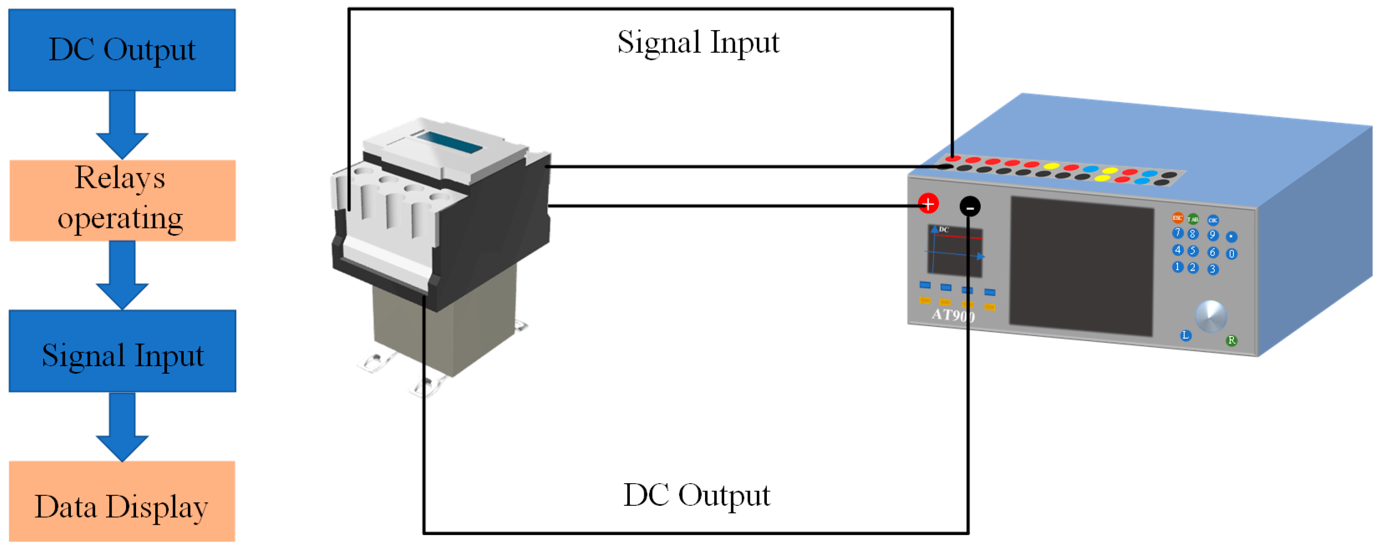
2.2. Test Platform and Methods

Currently, there is no unified standard for the auxiliary switch salt spray and alternating tests. Therefore, based on the relevant content in IEC60068-2-30-2007 “Environmental testing—Part 2: Test methods—Test Kb: Salt spray, alternating (sodium chloride)”, the following test was designed.
According to the relevant experimental requirements, this paper will use the LD-90B precision salt spray test chamber. Its own saltwater tank has a volume of 40 L to ensure its own spray time, and the temperature inside the chamber of 15–65 °C can meet the requirements of this test. It is also equipped with a high-precision temperature control system in order to ensure the test’s accuracy with an error no larger than 0.1 °C.
Before using the salt spray chamber, the 5% NaCl solution with a pH value between 6.5 and 7.5 should be configured according to the relevant standards and added to the saltwater tank, and then subsequent tests can be carried out [12]. The sample to be tested was placed in a salt spray test with an ambient temperature of 45 °C for a 4-h spray test, and then transferred to a constant temperature and humidity chamber to control the temperature and humidity at 45 °C and 95%, respectively, for a static 4-h period. For the convenience of subsequent statistics, it is now stipulated that a 4-h spray + 4-h storage is one test cycle, and the characteristic parameters will be extracted at the end of each test cycle.

2.3. Feature Selection and Extraction

Relays need to act promptly according to set targets in order to ensure rapid connection and disconnection of this part of the circuit. Failure to act in a timely manner may cause unpredictable losses due to chain reactions [13,14]. Therefore, the action time (pickup time, dropout time) was selected as a feature parameter in order to understand the changes in relay performance [15]. In addition, the intrusion of salt spray damages the coil and causes changes in the operating voltage (pickup voltage, dropout voltage). Therefore, the operating voltage (pickup voltage, dropout voltage) can also be a key parameter for measuring the performance of the relay itself. Through the comprehensive analysis of these two parameters, the ultimate effect of salt spray on the deterioration of the relay can be determined. Therefore, the above parameters were selected as feature parameters.
The AT-900 comprehensive automation testing system was proposed to measure the above parameters. This equipment has multiple signal input ports, which can simultaneously measure four parameters: action time (pickup, dropout) and operating voltage (pickup, dropout), as shown schematically in Figure 2. At the same time, the equipment has high measurement accuracy, fast response speed, and can realize automatic and manual measurement methods, ensuring the reliability of experimental results.

3. Results

Following the experimental plan outlined above, a salt spray aging test was conducted on the relay. During the experiment, significant rust was observed on the relay’s surface metal parts, and all of its parameters showed varying degrees of change. Therefore, this section will provide an in-depth analysis of the collected characteristic parameters in order to determine the effects of salt spray on the relay.

3.1. Relay Action Voltage Changes

During the salt spray test on the relay, severe rust was found on its surface metal parts, and solid NaCl was attached to its surface, as shown in Figure 3. With an increase in the test cycle, the degree of rust and salt spray adhesion significantly increased. The effect of the salt spray on the terminal screws was particularly noticeable, which caused damage during the wiring process.
To facilitate comparative analysis, the action voltage of the test sample was measured before the experiment. To ensure measurement accuracy, an automatic test mode was used with consistent step voltages and times of 0.1 V and 0.05 s, respectively. Relevant tests could only begin after ensuring that the testing connections were correct.
Following the previously described method, an accelerated salt spray aging test was conducted, and the action voltage was collected after each test. After ten aging cycles, the relay was unable to complete its action. Consequently, the data from the first nine tests and the data from the new relay were consolidated in Figure 4, with the horizontal and vertical axes representing the number of tests within each cycle and the operating voltage, respectively.
From the above figure, it can be seen that the contactor’s pull-in voltage was significantly affected by salt spray, and with the increase in the aging cycle, the pull-in voltage showed a fluctuating upward trend. The average pull-in voltage of a new contactor is only 102.38 V, while after nine aging cycles, its average voltage increases to 123.14 V, an increase of about 27.27%, which is a significant change. After the first salt spray aging, the pull-in voltage of the contactor increased by about 5.92 V, which is significant compared to the voltage changes in the following six cycles. Within 1–7 aging cycles, the pull-in voltage increased slowly, and the maximum voltage change occurred in the 7th cycle, with an increase of 1.45 V, which is far less than the change after the initial aging. With the increase in aging time, during the measurement of the pull-in voltage after the 8th cycle, it was found that the voltage increased sharply, reaching 124.63 V, an increase of about 7.14% compared to the previous cycle’s 116.32 V. After the 10th aging cycle, the contactor was unable to operate normally and was determined to be thoroughly damaged due to salt spray effects, so the data for that group was not displayed in the figure.
In the experimental process, in addition to collecting the pull-in voltage, another key parameter, the return voltage, was also measured, and the specific results are shown in Figure 5. From the figure, it can be clearly seen that the opening voltage changes significantly with the increase in test cycles. The average opening voltage of a new contactor is only 56.93 V, while after nine cycles of salt spray accelerated aging, the voltage increased to 71.26 V, an increase of 25.17%. The opening voltage, such as the pull-in voltage, also showed a fluctuating upward trend after being affected by salt spray, until it was unable to operate.

3.2. Changes in the Contactors’ Operating Time

During the testing process, it was observed that, in addition to the operating voltage, the operating time of the relay also underwent significant changes, with both the pull-in and release times showing an increasing trend. The pull-in voltage of the relay increased sharply due to the influence of salt spray, while the release time did not show a significant change. This section will provide a brief analysis of the time variation. Figure 6 shows the variation of the pull-in time.
After conducting 22 samples in each aging cycle, the variation of pull-in time was compiled and is shown in Figure 6a. The pull-in time fluctuated strongly and the data was scattered, making it difficult to visually observe the changes from the graph. To address this issue, the average pull-in time for each cycle was calculated and plotted against the aging variation with salt spray, as shown in Figure 6b.
From the graph, it can be observed that the relay’s pull-in time range in a new state was two to nine milliseconds, with a fast action process, ensuring that the relay completed its action within the specified time. After one cycle of salt spray aging, there was no significant change, and the average pull-in time was 10.83 milliseconds, which only increased by 5.72 milliseconds compared to the new relay, and its performance did not undergo significant changes. However, at the end of the second cycle, the average voltage increased sharply to 134.2 milliseconds, about 13 times larger. From this moment on, the relay’s performance gradually deteriorated, and at the end of the third cycle, the increase in pull-in time was the largest in the test process, about 234.51 milliseconds, an increase of 170% compared to the previous cycle. In the following four cycles, the pull-in time showed a slow upward trend, and the change in quantity was not significant. During this period, the pull-in time only increased by 13.19 milliseconds. At cycles 8 and 9, the relay’s pull-in time was 444.67 and 451.75, respectively, with a significant increase in action time and extreme degradation in performance.
The relay needs to be disconnected promptly within a short time to ensure circuit interruption, so its opening time is also crucial. To this end, the same method was used to collect the relay’s opening time and average opening time and plot them on Figure 7.
By comparison, it can be seen that the change in the relay’s opening time was similar to that of the pull-in time, showing a three-stage change. The initial stage was relatively stable, followed by a sharp increase that lasted for a long time in this stage. After undergoing the last two cycles of aging, the time again showed an upward trend. In the first two cycles, there was no significant change in the opening voltage, which was less than six milliseconds, allowing the relay to disconnect rapidly. After the sharp increase to 234.42 milliseconds, it returned to a stable state until the end of the seventh cycle. After the accelerated aging test, the opening time reached 412.55 milliseconds, which is a significant change compared to the initial state. The increase in the opening time can lead to slow relay action and increase the likelihood of accidents.

3.3. Analysis of Performance Degradation Mechanism

The relay’s surface seal was not tight, which allowed salt spray and moisture to enter through the wiring holes and gaps. This ingress of salt spray caused varying degrees of damage to the relay’s electrical and mechanical parts. Disassembly of the aged relay revealed that a large amount of white solid had adhered to the coil surface, which was due to the evaporation of water vapor from the NaCl solution on the coil surface, and the solid NaCl then accumulated and adhered to the coil surface as temperature and time increased. In addition, the relay spring may have experienced some degree of rusting on its surface due to long-term exposure to salt spray, leading to a decrease in its performance.
In the process of spraying, a large amount of salt spray invaded the interior of the relay, and the configured NaCl solution had a pH value of 6.6, showing weak acidity. The weak acid solution directly corroded the coil after destroying the original protective film on the surface of the coil, leading to a decrease in the quality factor (Q) of the coil and a subsequent decrease in the electromagnetic force generated on the coil. On the other hand, as a key component inside the relay, the performance of the spring directly affected the relay’s contact process. The content of Fe element was found to be up to 97% after the metal analyzer was used to measure the spring material. Fe is easily oxidized in humid and salt spray environments to produce rust. After rusting, the tensile strength, stiffness coefficient, and fatigue strength of the spring all decreased to varying degrees, thereby altering the elastic force generated by the spring itself.
During the relay’s operation, the connecting rod was affected by the electromagnetic force generated by the coil, driving the contact piece to overcome the spring force and move vertically downward, thus completing the circuit. The force acting on the relay when it was in the closed position is shown in Figure 8. Analysis shows that when the relay was closed, the spring force was less than the sum of gravity and electromagnetic force. Therefore, in the absence of changes in spring force and self-gravity, the electromagnetic force was the main factor affecting the relay’s operation.
According to the working principle of the relay, it was divided into two main stages during the suction process. The first stage occurred when the relay voltage rose but still no action occurred, and F + G < f under this moment. This was followed by the action phase, and F + Gf. Combined with the kinetic-related knowledge, we established its action process model as follows:
d ϕ d t = U i r
d U d t = F x f x , d x d t m
d x d t = v
Φ is the magnetic flux, the unit is Wb; x is the distance of movement; v is the speed of motion.
During operation, the relay coil could be viewed as a series circuit consisting of a resistance and an inductor, so the voltage balance equation was derived as follows:
U = i r + L d i d t + i d L d t
When a relay is energized, the electromagnetic force generated by the coil in the first stage increases with the operating voltage, while the relay does not operate at this time. When F + Gf, the direction of the combined force downward, at this time to enter the second stage of the relay, will be an action to complete the suction. After being affected by salt spray, the coil’s own permeability decreased and the NaCl adhered to the coil surface, which increased the leakage current, requiring higher voltage to provide the necessary electromagnetic force for contact closure. Moreover, with the increase in aging time, the deterioration of the coil deepens, forcing it to continuously increase the operating voltage in order to overcome the spring force and complete the action. This was the main reason for the increase in the relay’s contact closure voltage.
The voltage dropped during the relay breaking process, causing the electromagnetic force to change, and the relay did not act until F + G < f, when the relay made the breaking action. Similar to the suction process, the breaking process was also divided into two stages, where the critical point was the mechanical equilibrium point (F + G = f), from which it can be seen that the decline in relay performance was also the main cause of the rising breaking voltage.
As previously mentioned, during the measurement process using the tester, the stepping voltage remained consistent but, after being corroded by salt spray, the relay’s own performance decreased, and the electric field force provided by the same stepping voltage was not consistent. When the voltage crossed the critical contact closure voltage, the connecting rod drove the contact piece downward under the action of the electric field force and the external force was F + Gf. As shown in Figure 9, after the performance degradation, the electric field force provided by the stepping voltage decreased. At this point, the force ΔF1 generated by the stepping voltage of the new relay was greater than the ΔF2 generated after aging. Although both can be greater than the electric field force required for critical contact closure, the maximum electric field force F2 generated by the aging relay was inevitably less than F1 at the initial moment.
The electric field force F was reduced, while the gravity and spring forces themselves did not undergo significant changes. Therefore, the external force was reduced. In the experiment, the relay sample was not replaced, so the travel during the relay’s operation remained the same, and the initial speed was 0. Under the condition that the motion distance and initial velocity did not change, the acceleration had a critical impact on the relay’s contact closure time, and the change in the external force caused the relay’s contact closure time to increase. Therefore, it can be inferred that the coil’s performance degradation after being affected by salt spray caused the relay’s operation time to change.
Relays operating for a long time in salt spray environments are susceptible to environmental influences, resulting in changes in operating voltage and operating time, which significantly impact the normal operation of equipment. Therefore, strengthening the anti-corrosion treatment of internal components can effectively enhance the stability of the equipment. On the other hand, equipment should be designed with improved structural integrity to enhance its sealing performance and address the impact of external environments at the source.

4. Relay Life Assessment

If the relay is exposed to a long-term salt fog environment, its performance will decline. If it is not resolved in time, accidents can occur. Therefore, it is necessary to establish relevant models to achieve its status recognition [13,14]. As mentioned earlier, important indicators for judging the relay’s own status include characteristics such as pull-in time, release time, pull-in voltage, and release voltage. Therefore, this paper will use the collected parameters during the experimental process to establish a related diagnostic model to achieve the identification of the relay’s status after being affected by salt fog.

4.1. Model Environment and Data

All simulation experiments were conducted on a computer with an Intel(R) Core(TM) i7-9300H CPU, 8 GB memory, and Windows operating system. The software environment was Matlab2018b.
The training set and test set used in this paper were obtained through the previous experimental process, ensuring the reliability of the data. The dataset consists of samples in different conditions, and 70% of the samples were randomly selected as the training set, and 30% as the test set. In order to minimize experimental errors, it is necessary to normalize the data to improve the accuracy of the model as much as possible. In order to obtain a clearer understanding of the relay’s own condition, the existing data will be classified and divided into 1–5 levels according to their degree of degradation, as shown in Table 1 below.

4.2. Relay Status Identification Results

The results of the relay state recognition in the experiment using a BP neural network are shown in the figure. This model has 4 inputs and 5 outputs, with a total of 185 sets of samples, of which 148 are used for training and the remaining 37 are for testing. As shown in Figure 10, the original data is read into the system through the input layer, calculated by the hidden layer, and finally the corresponding output results are obtained, and the error between the output layer and the actual during training is used to improve the accuracy of the results through back propagation.
Figure 11 shows the BP neural network diagnosis results, from which it is clear that there are four types of errors in predicting the five states of the relay. All normal states of the relay were misjudged, and except for mild damage being correctly identified, the other states were misjudged to varying degrees. Analysis of the data shows that, due to the small difference in the initial state relay parameters and the relay parameters after short-term salt spray aging in terms of action time and action voltage, the data features are similar, resulting in serious misjudgment.
Figure 11b shows the confusion matrix of the test set, with each row representing a different fault category and the columns of the matrix representing the model’s diagnosis results. The matrix has two colors: blue and orange. Blue indicates that the true value and the model result match, while orange indicates a misjudgment, and the depth of the color reflects the accuracy/error rate. From the figure, it can be seen that the results of mild damage discrimination are the most accurate, while the results of severe deterioration and normal state relay discrimination are not ideal.
In the process of using the BP model to identify the state of the relay itself, due to the lack of feature learning ability and incomplete fitting of the model, the diagnosis results were not ideal [16], with an accuracy rate of only 78.6%. Therefore, it is necessary to optimize the model to improve the accuracy rate and ensure the credibility of the results in subsequent actual use.
To improve the accuracy of the relay state prediction model, based on the GA_BP model, the original data was used to predict its state, with a population size of 20, 30 iterations, and a crossover function of 0.8. The basic flow is shown in Figure 12 andtest results are shown in the Figure 13.
In Figure 11, it can be seen that the optimized model has significantly improved the accuracy in the process of identifying relay states, but the running speed has decreased relatively. Normal, mild, and severe damage can all be successfully predicted, with only one group of data misjudged in the prediction process of three-degree damage. Overall, the effect is ideal, and the accuracy has reached 91.8%.
The traditional BP neural network has a relatively low accuracy in identifying relay states, only 78.6%. The GA_BP algorithm has achieved a diagnostic accuracy of 91.8%, which is a significant improvement compared to before. Although the time has increased, it can still diagnose the relay’s own state within 1 min. The comparison results of the two approaches are shown in Table 2. Therefore, GA_BP was adopted to diagnose the relay’s own state. This model has undergone relevant testing at the Southern Power Grid’s ultra-high voltage test base and can accurately feedback the relay’s own state in a timely manner by inputting the collected data into the system, with certain engineering application value.

5. Conclusions

In this paper, we conducted salt spray accelerated aging experiments on a certain type of relay using an existing experimental platform, studied the deterioration of the relay under a salt spray environment, and analyzed the impact of external environmental factors on its operating voltage and operating time. At the same time, using the relevant data collected during the experimental process, we established a relay state recognition model based on the relay’s key parameters through GA_BP:
  • The relay’s seal is not airtight, which allows salt spray and moisture to enter the interior. The intrusion of salt spray causes different degrees of damage to the relay’s electrical and mechanical parts, with a large amount of NaCl solid adhering to the surface of the coil and spring, resulting in a decline in performance and affecting the normal operation of the relay.
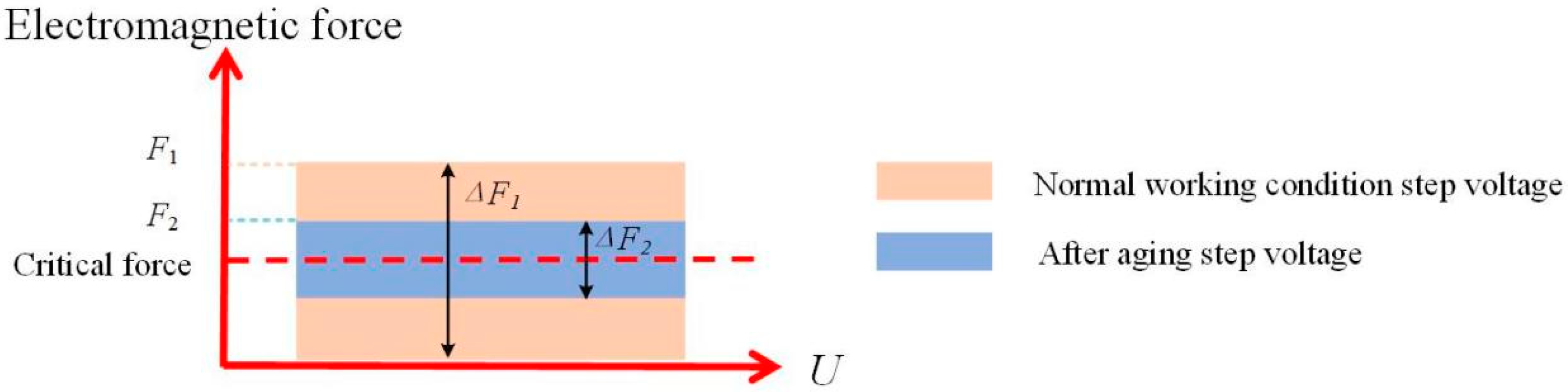
  • Under the influence of NaCl, the coil’s own magnetic permeability decreases, causing the electromagnetic force it produces under the same voltage to be reduced compared to normal conditions, which is the main reason for the change in its own operating voltage. On the other hand, the decrease in the electromagnetic force generated by the step voltage causes a decrease in the external force, resulting in an increase in the operating time.
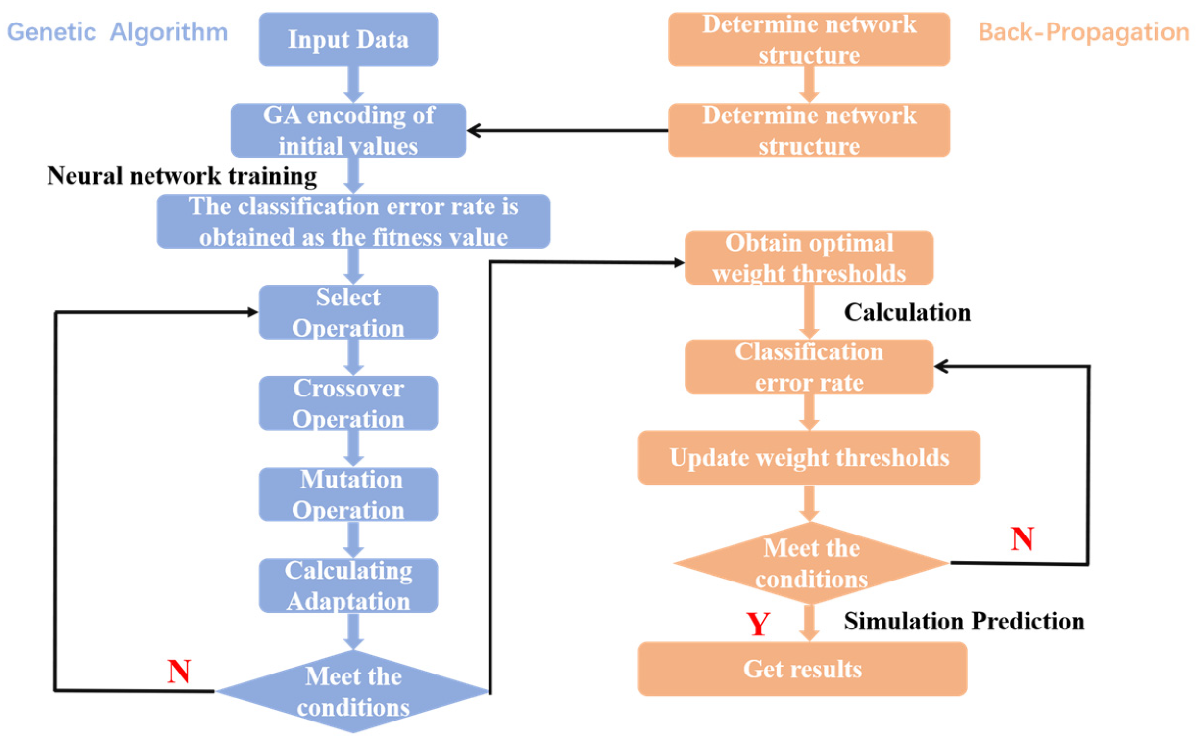
  • The GA_BP model established in this paper uses the relay’s operating voltage (pull-in, release) and operating time (pull-in, release) as input features to achieve recognition of the relay’s own state. The classification recognition model that we established has high accuracy, reaching 91.8%. At the same time, the model can evaluate the relay’s state at any given time by manually inputting any group of four-dimensional data.
  • The research results of this paper show that long-term exposure to a salt spray environment will lead to the deterioration of relay performance, resulting in changes in operating voltage and operating time, which easily causes accidents. Therefore, while improving the sealing performance of the equipment, the manufacturers should strengthen the anti-corrosion treatment of the internal components, as far as possible, in order to reduce the impact of salt spray on the outside. At the same time, the equipment to be put into operation should be tested regularly and its own performance should be evaluated in order to avoid accidents.

Author Contributions

Conceptualization, H.M.; formal analysis, H.M., C.G., F.Z., Y.Y. and H.Y.; Investigation, C.G., F.Z., Y.Y., H.Y. and S.Z.; writing—original draft, S.Z.; writing—review and editing, H.M. and H.Y. All authors have read and agreed to the published version of the manuscript.

Funding

This work was supported by the National Natural Science Foundation of China (Grant No. 52007138).

Data Availability Statement

Data sharing not applicable. No new data were created or analyzed in this study. Data sharing is not applicable to this article.

Conflicts of Interest

The authors declare no conflict of interest.

References

  1. Hadziefendic, N.; Trifunovic, J.; Kostic, M. Effects of a reduced torque on heating of electrical contacts in plugs and recepta-cles. IEEE Trans. Compon. Packag. Manuf. Technol. 2018, 8, 1905–1913. [Google Scholar] [CrossRef]
  2. Ren, W.; Zhang, C.; Du, Q.; Du, D.; Wang, H. Experimental investigation of cold adhesion failure physical mechanism of gold plated contact within the Micro-Electromechanical-Relay. Eng. Fail. Anal. 2021, 121, 105151. [Google Scholar] [CrossRef]
  3. Gonzalez, D.; Hopfeld, M.; Berger, F.; Schaaf, P. Investigation on Contact Resistance Behavior of Switching Contacts Using a Newly Developed Model Switch. IEEE Trans. Compon. Packag. Manuf. Technol. 2018, 8, 939–949. [Google Scholar] [CrossRef]
  4. Wan, B.; Fu, G.; Li, Y.; Zhao, Y.; Jia, M. Failure analysis of the electromagnetic relay contacts. Eng. Fail. Anal. 2016, 59, 304–313. [Google Scholar] [CrossRef]
  5. Li, Z.; Jiang, D.; Li, W.; Su, X.; Guo, H. Reliability analysis and failure prediction study of dynamic contact resistance on contact. In Proceedings of the Forty-Eighth IEEE Holm Conference on Electrical Contacts 2002, Orlando, FL, USA, 23 October 2002; IEEE: Piscataway, NJ, USA; pp. 61–65. [Google Scholar]
  6. Liu, J.; Zhang, M.; Zhao, N.; Chen, A. A Reliability Assessment Method for High Speed Train Electromagnetic Relays. Energies 2018, 11, 652. [Google Scholar] [CrossRef] [Green Version]
  7. Hernanda, I.S.; Kartinisari, E.N.; Asfani, D.A.; Fahmi, D. Analysis of protection failure effect and relay coordination on reliability index. In Proceedings of the 2014 The 1st International Conference on Information Technology, Computer, and Electrical Engineering 2014, Ho Chi Minh City, Vietnam, 24–24 November 2014; IEEE: Piscataway, NJ, USA; pp. 366–371. [Google Scholar]
  8. Ramirez-Laboreo, E.; Sagues, C.; Llorente, S. A new model of electromechanical relays for predicting the motion and electro-magnetic dynamics. IEEE Trans. Ind. Appl. 2016, 52, 2545–2553. [Google Scholar] [CrossRef] [Green Version]
  9. Li, W.; Li, K.; Sun, L.; Zhao, S.; Ji, L. The test data verifying & prediction model of electrical contact. In Proceedings of the 50th IEEE Holm Conference on Electrical Contacts and the 22nd International Conference on Electrical Contacts Electrical Contacts, Seattle, WA, USA, 23–23 September 2004; IEEE: Piscataway, NJ, USA; pp. 429–436. [Google Scholar]
  10. Guo, J.; Zhang, G.; Bi, Y.; Li, Y. Life prediction of automotive electromagnetic relay based on wavelets neural network. Chem. Eng. Trans. 2017, 62, 1213–1218. [Google Scholar]
  11. Sun, J.; Xing, H.; Wu, J. Distributed Sea Clutter Denoising Algorithm Based on Variational Mode Decomposition. Instrumentation 2020, 7, 23–32. [Google Scholar]
  12. IEC60068-2-41-1976; Environmental Testing for Electric and Electronic Products. Part 2. Available online: https://webstore.iec.ch/publication/523 (accessed on 7 June 2023).
  13. Kadechkar, A.; Moreno-Eguilaz, M.; Riba, J.-R.; Capelli, F. Low-Cost Online Contact Resistance Measurement of Power Connectors to Ease Predictive Maintenance. IEEE Trans. Instrum. Meas. 2019, 68, 4825–4833. [Google Scholar] [CrossRef] [Green Version]
  14. Puyol, R.; Suárez, S. A Contact Resistance Measurement Setup for the Study of Novel Contacts; IEEE: Piscataway, NJ, USA, 2017; pp. 1–4. [Google Scholar]
  15. Wang, Z.; Zhai, G.; Ren, W.; Huang, X.; Yu, Q. Research on accelerated storage degradation testing for aerospace electro-magnetic relay. In Proceedings of the 2012 IEEE 58th Holm Conference on Electrical Contacts (Holm), Portland, OR, USA, 23–26 September 2012; IEEE: Piscataway, NJ, USA; pp. 1–8. [Google Scholar]
  16. Jiménez, T.; Merayo, N.; Andrés, A.; Durán, R.J.; Aguado, J.C.; de Miguel, I.; Fernández, P.; Lorenzo, R.M.; Abril, E.J. An auto-tuning PID control system based on genetic algorithms to provide delay guarantees in Passive Optical Networks. Expert Syst. Appl. 2015, 42, 9211–9220. [Google Scholar] [CrossRef]
Figure 1. JZC3-40DT type relay.
Energies 16 04843 g001
Figure 2. Relay operation test.
Energies 16 04843 g002
Figure 3. Relay internal damage.
Energies 16 04843 g003
Figure 4. Variation of pull-in voltage with aging cycle.
Energies 16 04843 g004
Figure 5. Variation of release voltage with aging cycle.
Energies 16 04843 g005
Figure 6. Variation of pull-in time with aging cycle.
Energies 16 04843 g006
Figure 7. Variation of release time with aging cycle.
Energies 16 04843 g007
Figure 8. Contact piece force diagram.
Energies 16 04843 g008
Figure 9. Step voltage at different operating conditions.
Energies 16 04843 g009
Figure 10. BP Network structures.
Energies 16 04843 g010
Figure 11. BP neural network classification results graph.
Energies 16 04843 g011
Figure 12. GA_BP neural network flowchart.
Energies 16 04843 g012
Figure 13. GA_BP neural network classification results graph.
Energies 16 04843 g013
Table 1. Relay Status Classification.
Degradation LevelNumber of Groups IncludedFailure Tags
Normal state11
Mild injury2, 32
Early warning status4, 5, 63
Severe injury7, 8, 94
Severe degradation105
Table 2. Comparison chart of the results of different model evaluation indicators.
Fault Diagnosis ModelAccuracy/%Time/s
BP78.68.12
GA_BP91.832.75
Disclaimer/Publisher’s Note: The statements, opinions and data contained in all publications are solely those of the individual author(s) and contributor(s) and not of MDPI and/or the editor(s). MDPI and/or the editor(s) disclaim responsibility for any injury to people or property resulting from any ideas, methods, instructions or products referred to in the content.

