
Permanent Magnet Flux Linkage Analysis and Maximum Torque per Ampere (MTPA) Control of High Saturation IPMSM

Abstract
:1. Introduction
2. Conventional IPMSM Model and MTPA Control
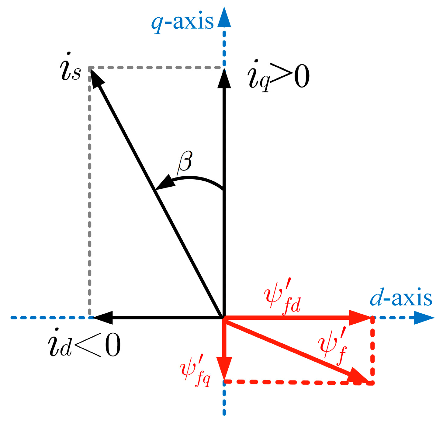
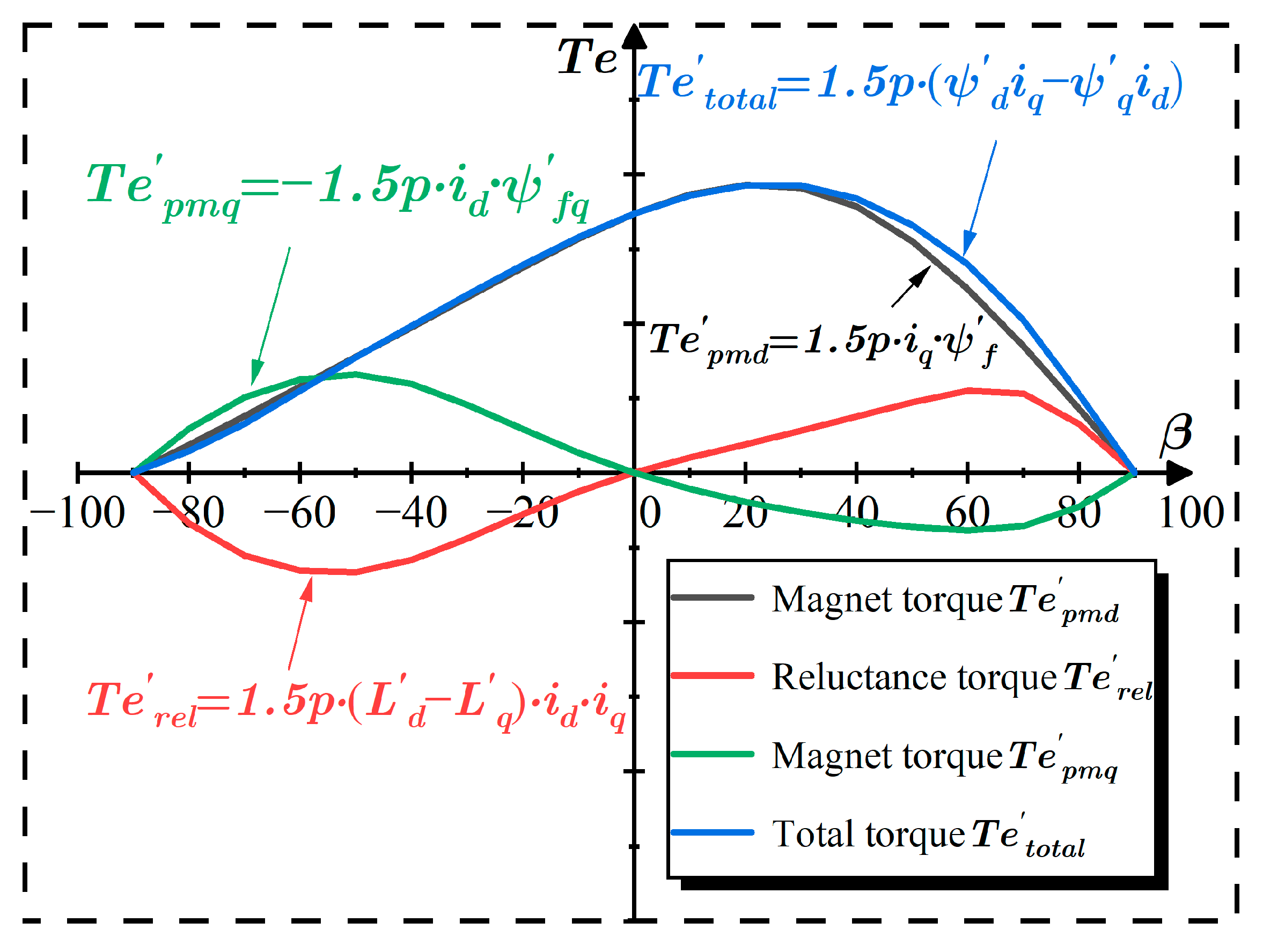
3. PM Flux Linkage Analysis and Proposed MTPA Control
3.1. Proposed IPMSM Model and Fitting Models
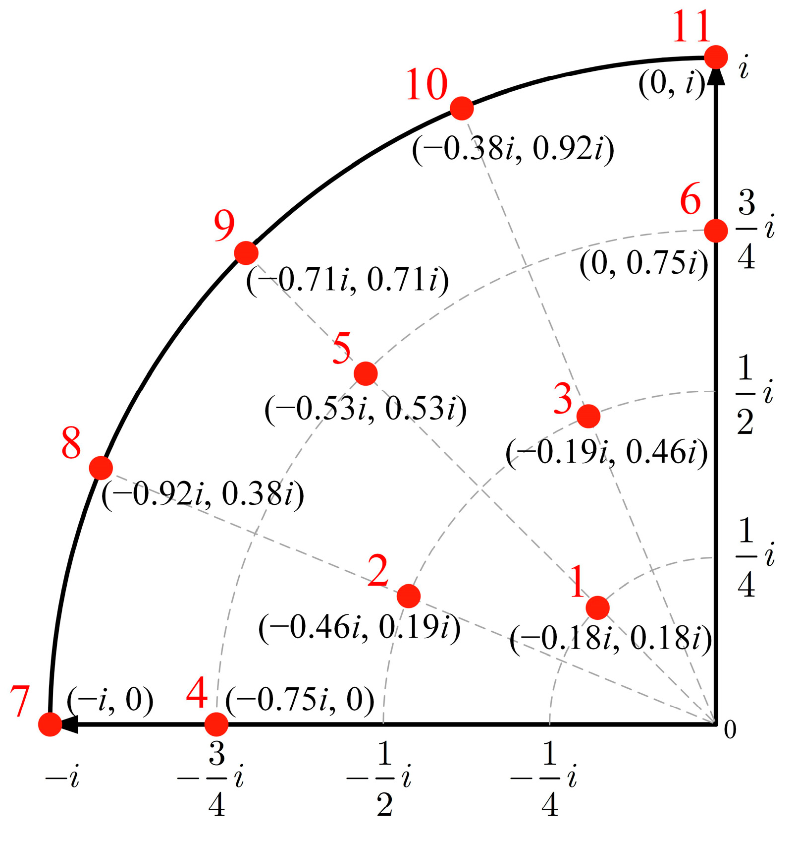
3.2. Determination of the Coefficients and Implementation of the MTPA Control
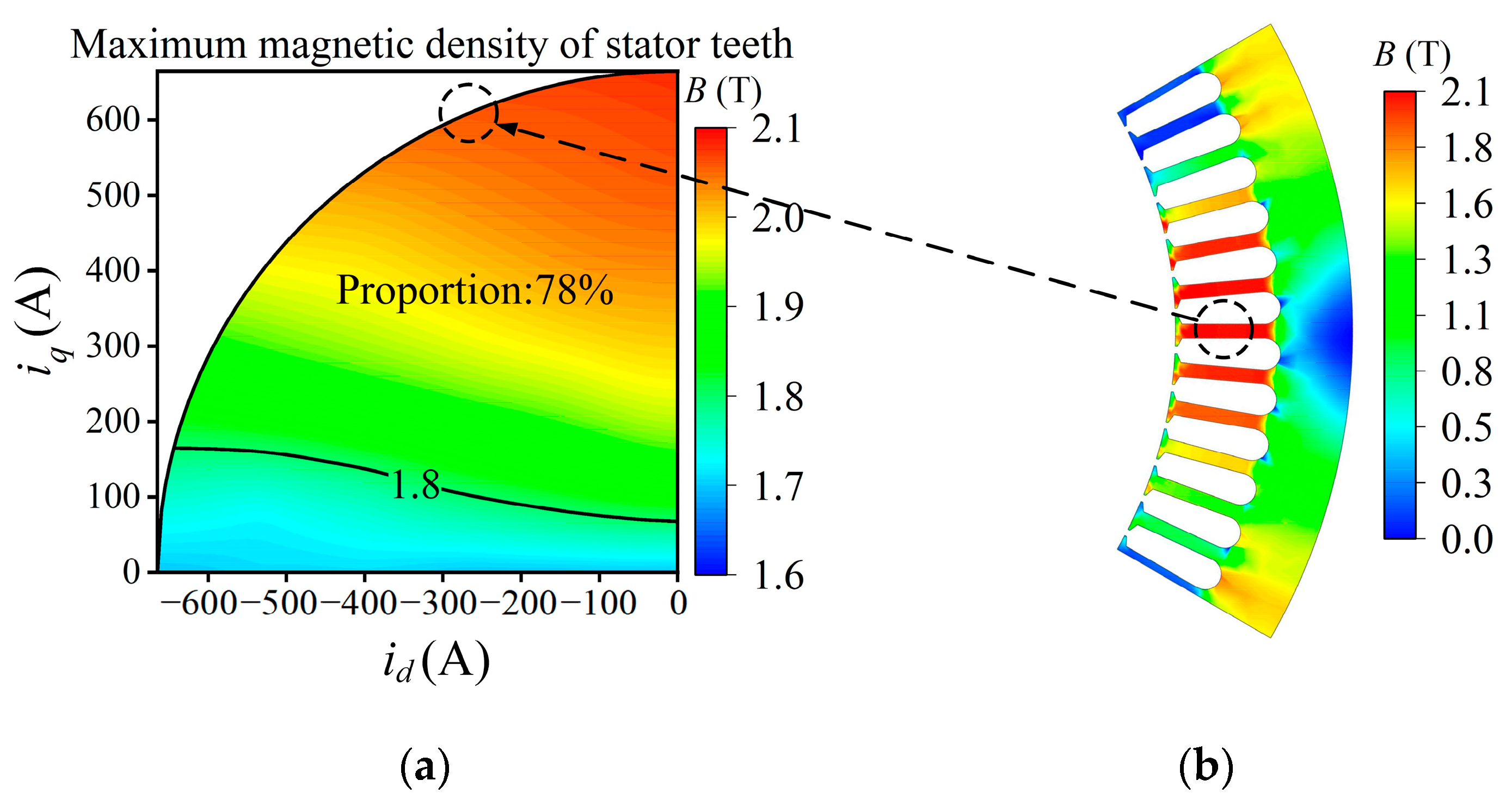
4. Simulation Analysis and Verification
5. Experimental Results
6. Conclusions
Author Contributions
Funding
Data Availability Statement
Conflicts of Interest
References
- Martinez, M.; Fernandez, D.; Reigosa, D.; Guerrero, J.M.; Briz, F. Wireless torque pulsations measurement system for PMSMs. IEEE Trans. Ind. Appl. 2020, 56, 6467–6476. [Google Scholar] [CrossRef]
- Taherzadeh, M.; Hamida, M.A.; Ghanes, M.; Koteich, M. A new torque observation technique for a PMSM considering unknown magnetic conditions. IEEE Trans. Ind. Electron. 2021, 68, 1961–1971. [Google Scholar] [CrossRef]
- Uddin, M.N.; Rahman, M.M. Online torque-flux estimation-based nonlinear torque and flux control scheme of IPMSM drive for reduced torque ripples. IEEE Trans. Power Electron. 2019, 34, 636–645. [Google Scholar] [CrossRef]
- Pan, C.-T.; Sue, S.-M. A linear maximum torque per ampere control for IPMSM drives over full-speed range. IEEE Trans. Energy Convers. 2005, 20, 359–366. [Google Scholar] [CrossRef]
- Liu, K.; Feng, J.; Guo, S.; Xiao, L.; Zhu, Z.-Q. Identification of flux linkage map of permanent magnet synchronous machines under uncertain circuit resistance and inverter nonlinearity. IEEE Trans. Ind. Inform. 2018, 14, 556–568. [Google Scholar] [CrossRef]
- Raja, R.; Sebastian, T.; Wang, M. Online stator inductance estimation for permanent magnet motors using PWM excitation. IEEE Trans. Transp. Electrif. 2019, 5, 107–117. [Google Scholar] [CrossRef]
- Ge, H.; Jiang, J.W.; Ye, J.; Emadi, A. Behavior study of permanent magnet synchronous machines based on a new normalized model. IEEE Trans. Ind. Electron. 2019, 66, 7539–7550. [Google Scholar] [CrossRef]
- Sokolov, E.; Mihov, M. Parameter Estimation of an Interior Permanent Magnet Synchronous Motor. In Proceedings of the 16th Conference on Electrical Machines, Drives and Power Systems (ELMA), Varna, Bulgaria, 6–8 June 2019; pp. 1–5. [Google Scholar]
- Feng, G.; Lai, C.; Mukherjee, K.; Kar, N.C. Online PMSM Magnet Flux-Linkage Estimation for Rotor Magnet Condition Monitoring Using Measured Speed Harmonics. IEEE Trans. Ind. Appl. 2017, 53, 2786–2794. [Google Scholar] [CrossRef]
- Ge, H.; Bilgin, B.; Emadi, A. Global loss minimization control of PMSM considering cross-coupling and saturation. In Proceedings of the 2015 IEEE Energy Conversion Congress and Exposition (ECCE), Montreal, QC, Canada, 20–24 September 2015; pp. 6139–6144. [Google Scholar]
- Ahmad, H.; Ro, J.-S. Analysis and design optimization of V-shaped permanent magnet vernier motor for torque density improvement. IEEE Access 2021, 9, 13542–13552. [Google Scholar] [CrossRef]
- Sun, T.; Wang, J.; Chen, X. Maximum torque per ampere (MTPA) control for interior permanent magnet synchronous machine drives based on virtual signal injection. IEEE Trans. Power Electron. 2015, 30, 5036–5045. [Google Scholar] [CrossRef]
- Babel, A.S.; Cintron-Rivera, J.G.; Strangas, E.G. A multiple look-up table torque controller for improved performance of IPM machines. In Proceedings of the 2013 International Electric Machines & Drives Conference, Chicago, IL, USA, 12–15 May 2013; pp. 521–525. [Google Scholar]
- Kim, S.M.; Kwon, T. A simple method to minimize effects of temperature variation on IPMSM control in real-time manner. In Proceedings of the 2014 IEEE Energy Conversion Congress and Exposition (ECCE), Pittsburgh, PA, USA, 14–18 September 2014; pp. 4212–4217. [Google Scholar]
- Xia, J.; Guo, Y.; Li, Z.; Jatskevich, J.; Zhang, X. Step-signal-injection-based robust MTPA operation strategy for interior permanent magnet synchronous machines. IEEE Trans. Energy Convers. 2019, 34, 2052–2061. [Google Scholar] [CrossRef]
- Dianov, A.; Anuchin, A. Adaptive maximum torque per ampere control for IPMSM drives with load varying over mechanical revolution. IEEE J. Emerg. Sel. Top. Power Electron. 2022, 10, 3409–3417. [Google Scholar] [CrossRef]
- Lai, C.; Feng, G.; Mukherjee, K.; Tjong, J.; Kar, N.C. Maximum torque per ampere control for IPMSM using gradient descent algorithm based on measured speed harmonics. IEEE Trans. Ind. Inform. 2018, 14, 1424–1435. [Google Scholar] [CrossRef]
- de Castro, A.G.; Guazzelli, P.R.U.; de Oliveira, C.M.R.; Pereira, W.C.D.A.; de Paula, G.T.; Monteiro, J.R.B.D.A. Optimized current waveform for torque ripple mitigation and MTPA operation of PMSM with back EMF harmonics based on genetic algorithm and artificial neural network. IEEE Lat. Am. Trans. 2020, 18, 1646–1655. [Google Scholar] [CrossRef]
- Tang, Q.; Shen, A.; Luo, P.; Shen, H.; He, X. IPMSMs sensorless MTPA control based on virtual q-axis inductance by using virtual high-frequency signal injection. IEEE Trans. Ind. Electron. 2020, 67, 136–146. [Google Scholar] [CrossRef]
- Sun, T.; Koç, M.; Wang, J. MTPA control of IPMSM drives based on virtual signal injection considering machine parameter variations. IEEE Trans. Ind. Electron. 2018, 65, 6089–6098. [Google Scholar] [CrossRef] [Green Version]
- Kim, H.; Lee, Y.; Sul, S.; Yu, J.; Oh, J. Online MTPA control of IPMSM based on robust numerical optimization technique. IEEE Trans. Ind. Appl. 2019, 55, 3736–3746. [Google Scholar] [CrossRef]
- Yu, Y.; Huang, X.; Li, Z.; Wu, M.; Shi, T.; Cao, Y.; Yang, G.; Niu, F. Full parameter estimation for permanent magnet synchronous motors. IEEE Trans. Ind. Electron. 2022, 69, 4376–4386. [Google Scholar] [CrossRef]
- Rabiei, A.; Thiringer, T.; Alatalo, M.; Grunditz, E.A. Improved maximum-torque-per-ampere algorithm accounting for core saturation, cross-coupling effect, and temperature for a PMSM intended for vehicular applications. IEEE Trans. Transp. Electrif. 2016, 2, 150–159. [Google Scholar] [CrossRef]
- Tinazzi, F.; Zigliotto, M. Torque estimation in high-efficency IPM synchronous motor drives. IEEE Trans. Energy Convers. 2015, 30, 983–990. [Google Scholar] [CrossRef]
- Miao, Y.; Ge, H.; Preindl, M.; Ye, J.; Cheng, B.; Emadi, A. MTPA fitting and torque estimation technique based on a new flux-linkage model for interior-permanent-magnet synchronous machines. IEEE Trans. Ind. Appl. 2017, 53, 5451–5460. [Google Scholar] [CrossRef]
- Feng, G.; Lai, C.; Han, Y.; Kar, C. Fast maximum torque per amper (MTPA) angle detection for interior PMSMs using online polynomial curve fitting. IEEE Trans. Power Electron. 2022, 37, 2045–2056. [Google Scholar]
- Lee, K.; Ha, J.; Simili, D.V. Analysis and suppression of slotting and cross-coupling effects on current control in PM synchronous motor drives. IEEE Trans. Power Electron. 2019, 34, 9942–9956. [Google Scholar] [CrossRef]
- Shi, Y.; Chai, J.; Sun, X.; Mu, S. Detailed description and analysis of the cross-coupling magnetic saturation on permanent magnet synchronous motor. J. Eng. 2018, 2018, 1855–1859. [Google Scholar] [CrossRef]
- Thul, A.; Groschup, B.; Hameyer, K. Influences on the Accuracy of Torque Calculation for Permanent Magnet Synchronous Machines. IEEE Trans. Energy Convers. 2020, 35, 2261–2268. [Google Scholar] [CrossRef]


| Parameters | Quantity | Parameters | Quantity |
|---|---|---|---|
| Rated power | 300 kW | Pole pairs | 3 |
| Rated current | 470 A | PM flux linkage | 0.332 Wb |
| Rated speed | 3000 r/min | Stator resistance | 0.005 Ω |
| Rated torque | 955 Nm | d-axis inductance | 0.4723 mH |
| Rated frequency | 150 Hz | q-axis inductance | 1.0228 mH |
| Coefficient | ai | bi | ci |
|---|---|---|---|
| i = 0 | −5.55 × 10⁻⁴ | 0.342 | −3.91 × 10⁻⁴ |
| i = 1 | −1.12 × 10⁻⁸ | −1.32 × 10⁻⁴ | −1.23 × 10⁻⁷ |
| i = 2 | 6.23 × 10⁻⁷ | −4.37 × 10⁻⁵ | 3.43 × 10⁻⁷ |
| i = 3 | −1.46 × 10⁻¹⁰ | −1.34 × 10⁻⁷ | 0 |
| i = 4 | 0 | −5.41 × 10⁻⁸ | 0 |
| Coefficient | ai | bi | ci |
|---|---|---|---|
| i = 0 | −6.28 × 10⁻⁴ | 0.317 | −3.34 × 10⁻⁴ |
| i = 1 | −1.13 × 10⁻⁷ | −6.19 × 10⁻⁵ | −9.24 × 10⁻⁸ |
| i = 2 | 6.97 × 10⁻⁷ | −1.1 × 10⁻⁴ | 2.54 × 10⁻⁷ |
| i = 3 | 1.92 × 10⁻¹⁰ | −2.3 × 10⁻⁷ | 0 |
| i = 4 | 0 | −8.23 × 10⁻⁹ | 0 |
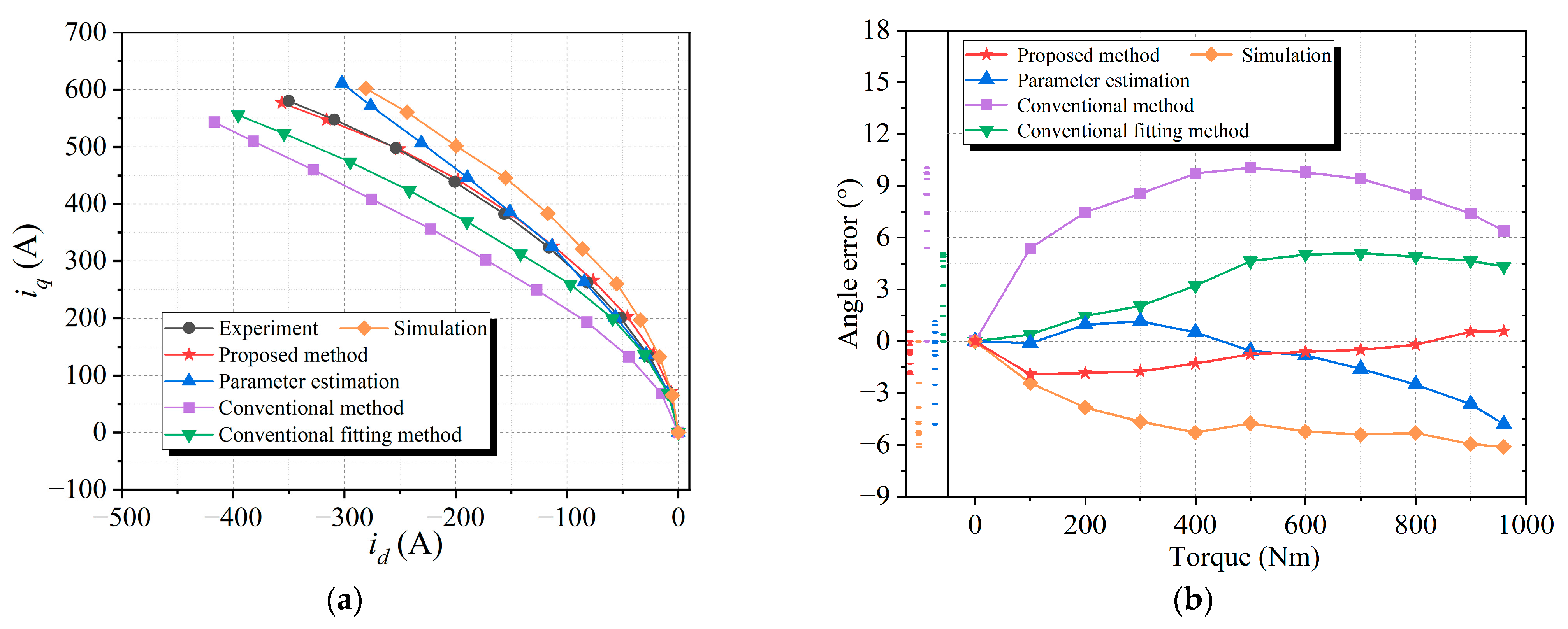
| Methods | Errors at Rated Load |
|---|---|
| Proposed | 0.6° |
| Simulation | −6.1° |
| Conventional | 6.4° |
| Conventional fitting | 4.3° |
| Parameter estimation | −4.8° |
Disclaimer/Publisher’s Note: The statements, opinions and data contained in all publications are solely those of the individual author(s) and contributor(s) and not of MDPI and/or the editor(s). MDPI and/or the editor(s) disclaim responsibility for any injury to people or property resulting from any ideas, methods, instructions or products referred to in the content. |
© 2023 by the authors. Licensee MDPI, Basel, Switzerland. This article is an open access article distributed under the terms and conditions of the Creative Commons Attribution (CC BY) license (https://creativecommons.org/licenses/by/4.0/).
Share and Cite
Li, C.; Zhang, W.; Gao, J.; Huang, S. Permanent Magnet Flux Linkage Analysis and Maximum Torque per Ampere (MTPA) Control of High Saturation IPMSM. Energies 2023, 16, 4717. https://doi.org/10.3390/en16124717
Li C, Zhang W, Gao J, Huang S. Permanent Magnet Flux Linkage Analysis and Maximum Torque per Ampere (MTPA) Control of High Saturation IPMSM. Energies. 2023; 16(12):4717. https://doi.org/10.3390/en16124717
Chicago/Turabian StyleLi, Chengxu, Wenjuan Zhang, Jian Gao, and Shoudao Huang. 2023. "Permanent Magnet Flux Linkage Analysis and Maximum Torque per Ampere (MTPA) Control of High Saturation IPMSM" Energies 16, no. 12: 4717. https://doi.org/10.3390/en16124717