Review

Review of Thermal Management Technology for Electric Vehicles

1
School of Mechanical Engineering, Beijing Institute of Technology, Beijing 100084, China
2
Fluids and Thermofluids Research Group, Faculty of Engineering, University of Nottingham, Nottingham NG7 2RD, UK
*
Authors to whom correspondence should be addressed.
Energies 2023, 16(12), 4693; https://doi.org/10.3390/en16124693
Submission received: 11 May 2023 / Revised: 9 June 2023 / Accepted: 10 June 2023 / Published: 14 June 2023

Abstract

:
The burgeoning electric vehicle industry has become a crucial player in tackling environmental pollution and addressing oil scarcity. As these vehicles continue to advance, effective thermal management systems are essential to ensure battery safety, optimize energy utilization, and prolong vehicle lifespan. This paper presents an exhaustive review of diverse thermal management approaches at both the component and system levels, focusing on electric vehicle air conditioning systems, battery thermal management systems, and motor thermal management systems. In each subsystem, an advanced heat transfer process with phase change is recommended to dissipate the heat or directly cool the target. Moreover, the review suggested that a comprehensive integration of AC systems, battery thermal management systems, and motor thermal management systems is inevitable and is expected to maximize energy utilization efficiency. The challenges and limitations of existing thermal management systems, including system integration, control algorithms, performance balance, and cost estimation, are discussed, along with potential avenues for future research. This paper is expected to serve as a valuable reference for forthcoming research.

1. Introduction

Presently, the world is grappling with numerous environmental challenges, such as global warming and resource depletion [1]. Studies have indicated that the transportation sector significantly contributes to global energy consumption, with automotive energy consumption accounting for over 30% of total oil energy consumption in recent years [2]. The exhaustion of oil reserves and the harmful environmental consequences of burning fossil fuels have led the United Nations and governments globally to enforce restrictions on fuel vehicles to achieve sustainable development goals [3]. Consequently, many companies are vigorously developing more environmentally friendly and energy-efficient products, including electric vehicles (EVs).
EVs have surfaced as the most viable alternative to internal combustion engine vehicles (ICEVs) due to their zero-emission capabilities on the road and various power source options [4]. Depending on the power source, EVs can be categorized as battery electric vehicles (BEVs), fuel cell electric vehicles (FCEVs), or hybrid electric vehicles (HEVs) [5]. Despite their potential, the evolution of EVs faces substantial thermal challenges, such as ensuring cabin thermal comfort, battery thermal safety, electric motor heat resistance, and addressing thermal integration. These challenges necessitate the adoption of novel thermal management solutions to improve the safety, reliability, and performance of EVs.
The thermal management of EVs involves the management of heat generated by various components, including the cabin, battery, and motor. The EV thermal management systems (EVTMSs) encompass cabin thermal management (CTM), battery thermal management (BTM), and motor thermal management (MTM) [6]. Air conditioning (AC) systems are a crucial component of EVTMS as they provide the necessary cooling or heating capacity for the cabin or the entire system [7]. However, traditional AC systems employing the PTC heating method consume significant energy, reducing the EV range at low ambient temperatures as well as contributing to lower energy efficiency. Heat pump systems offer an alternative but face challenges such as low-temperature heat production capability [8]. Enhancing the efficiency of compressors, the heat transfer performance of heat exchangers, and other critical AC system components is an area of significant research focus to improve their overall performance. Meanwhile, traditional refrigerants such as R134a have high global warming potential (GWP) values, making them environmentally unfriendly. The roadmap for the phasing out of HFC refrigerants has been proposed and R134a will shortly be replaced by more friendly refrigerants [9]. With the emergence of more eco-friendly refrigerants, it is very essential to develop efficient AC systems to extend EV range and to address environmental concerns.
Another critical aspect of EVTMS is managing heat accumulation within battery packs, particularly at high ambient temperatures, to prevent thermal runaways and ensure driving safety [10]. Advanced cooling systems such as liquid cooling provide efficient heat dissipation and maintain optimal temperature ranges for EV components. Phase change materials (PCM) and heat pipes offer alternative cooling methods, which can provide advantages such as being lightweight and having high cooling efficiency [11]. The transition toward higher power densities, torque densities, and faster speeds in electric motors has resulted in increased heat generation within the windings and mechanical components during operation, ultimately leading to decreased performance and service life [12]. Various thermal management systems have been extensively investigated to address these issues. In summary, efficient EVTMS components are crucial for driving safety and the lifespan of EVs.
The EVTMS systems manage the heat generated by different components either independently or in an integrated manner. Stand-alone thermal management systems operate independently, which allows for the identification and optimization of heat transfer weaknesses within a particular system but does not consider the energy coupling between subsystems [13]. As battery and motor power densities increase, separate thermal management systems struggle to meet thermal management requirements. Several relevant review papers critically reviewed solutions for separate cabin [14,15,16], battery [17,18], and motor [19] thermal management systems, offering new perspectives. By contrast, integrated thermal management systems combine multiple subsystems to distribute heat appropriately, making them a popular trend in EVTMS due to their ability to increase energy density. Therefore, this paper aims to present a comprehensive examination of the thermal management requirements of EVs. The respective thermal management solutions are discussed, and their combination in an integrated thermal management system is summarized to reveal compact and energy-efficient EVTMS solutions.
The paper is structured as follows: Section 2 discusses the thermal management requirements of electric vehicles. Section 3 reviews various solutions for AC systems, and Section 4 presents solutions for battery and motor thermal management systems. Section 5 summarizes the solutions for integrated thermal management systems. Section 6 presents the conclusions, as well as the trends and challenges of thermal management systems.

2. Electric Vehicle Thermal Management Requirements

2.1. Cabin Thermal Management Requirements

The cabin of a vehicle provides the environmental conditions for the driver during travel. Harsh driving conditions can cause driver fatigue and cognitive impairment, as demonstrated by existing literature [20], which highlights the importance of cabin thermal management in the automotive industry [21]. Achieving optimal thermal comfort in the cabin requires regulating various parameters, including temperature, humidity, and airflow, to maintain levels within the desired comfort range. It is essential to note that thermal management needs for the cabin may vary between summer and winter seasons [22], as shown in Table 1.
Recent studies have classified cabin thermal load calculation methods into three categories: steady-state heat transfer method, quasi-steady-state heat transfer method, and unsteady-state heat transfer method. Due to the complex nature of cabin thermal load, which involves various factors, as shown in Figure 1, the steady-state heat transfer method is commonly used for thermal load estimation in current investigations [23]. To simplify the modeling process of the electric vehicle cabin and improve the speed and accuracy of thermal simulation, models custom-built or pre-designed using multiphysics field simulation software such as MATLAB SimDriveline [24], MATLAB/Simulink [25], AMESim [26], and Dymola/Modelica [27] are employed.

2.2. Power Battery Thermal Management Requirements

Li-ion batteries are considered the most suitable power source for electric vehicles due to their numerous advantages over other rechargeable technologies, such as high energy density, low self-discharge rates, extended cycle life, and lightness [18,28,29,30]. Studies have indicated that the theoretical operational temperature range of Li-ion batteries is between –10 °C and 50 °C [31]. However, investigations have demonstrated that the battery undergoes a capacity decay phenomenon at low temperatures, and aging is accelerated when the temperature exceeds 50 °C [32]. Operating at high temperatures can impact charge/discharge efficiencies, battery life, internal electrochemical reactions, and safety [33,34]. Figure 2 shows the battery thermal runaway positive feedback loop and the resulting chain responses during thermal runaway [35]. Therefore, the existing literature suggests that optimal battery thermal management requires maintaining the battery temperature within the recommended operating temperature range, typically between 15 °C and 35 °C, to maximize performance and ensure safety [36]. When batteries are grouped into packs, thermal inconsistency must be considered, and the maximum temperature variation between battery cells within a group should not exceed 5 °C [37].
Various heat generation models have been proposed to accurately describe the thermal characteristics of batteries, including the electrochemical-thermal model [38], the electro-thermal model [39], and data-driven models based on intelligent algorithms [40]. The electrochemical-thermal model focuses on the internal structure of the cell, the thermal characteristics of the components, and the electrochemical reaction process. This model, based on electrochemical reaction kinetics and thermodynamics, describes the cell’s current, voltage, heat production, and heat transfer processes during electrochemical reactions, including the diffusion migration of lithium ions and changes in electrolyte concentration. The most commonly used electrochemical-thermal models are the single particle (SP) model [41] and the pseudo-two-dimensional (P2D) model [42]. However, from an engineering perspective, simplification of the models is necessary due to the inclusion of multiple coupled partial differential equations (PDEs) [43]. The electro-thermal model examines the electric and temperature fields inside a single cell from a macroscopic viewpoint. Based on the equivalent circuit approach, the model studies the battery’s heat production and temperature distribution based on the current density distribution and potential over the electrodes [44]. Hence, the physics-based equivalent circuit model has been considered the core of advanced safety and health management algorithms for next-generation battery thermal management systems [45]. Moreover, data-driven models based on intelligent algorithms make it feasible to estimate the electrical and thermal states of Li-ion batteries [46,47,48].

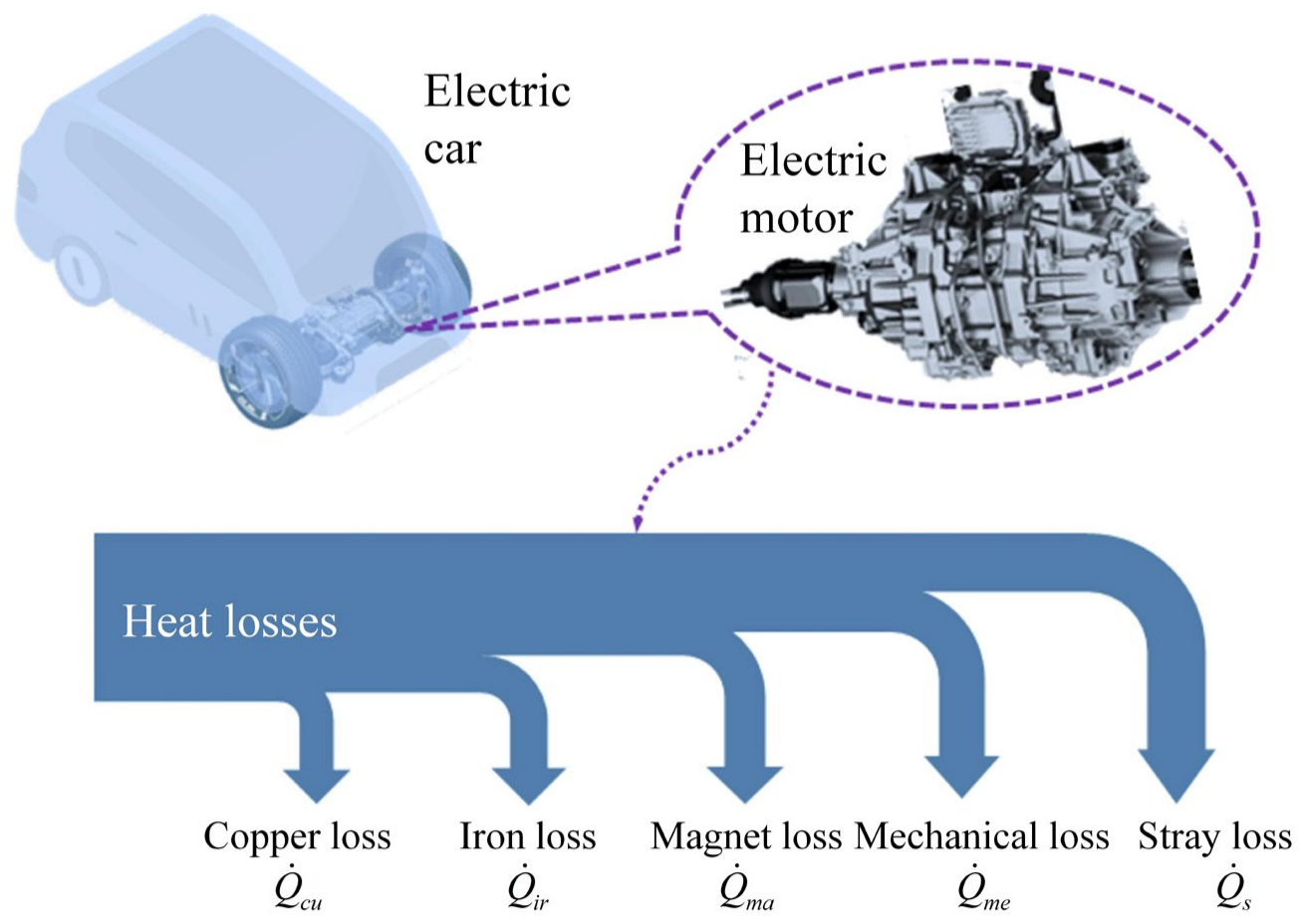
2.3. Electric Motor Thermal Management Requirements

To meet the increasing demand for electric vehicles, motors must exhibit higher power density, torque density, and speed [49,50]. This leads to a significant increase in loss density and temperatures that can cause short circuits, demagnetization of the magnet, and other issues [51]. Insufficient cooling of the motor will result in a rapid decrease in performance parameters of the electric motor, including power density, durability, and driving range per single charge [52]. For permanent magnet motors, high temperatures can also lead to demagnetization of the magnets embedded within the rotor [53,54]. The motor plays a crucial role in the energy output of electric vehicles and generates a considerable amount of heat during operation, as depicted in Figure 3 [19]. The most common electric vehicle motors include AC induction motors, switched reluctance motors, and permanent magnet synchronous motors [51]. Depending on the size of the electric vehicle motor, the heat generation power can range from 2.5–6 kW, 6–10 kW, and 10–15 kW, resulting in different thermal management requirements [55]. Two commonly used motor thermal management methods are air and liquid cooling [56,57,58]. Air cooling typically involves natural and forced air cooling and air impingement cooling [59]. On the other hand, liquid cooling mediums typically include coolant fluids and transformer oil, among others [60]. Numerous studies have been conducted to design various structural forms for both cooling methods to address the thermal management requirements of motors.
Several theoretical modeling methods have been proposed to provide academic support for meeting the thermal management requirements of electric motors. The primary theoretical modeling methods include the finite element method (FEM), lumped-parameter thermal network (LPTM) method, and computational fluid dynamics (CFD) method [61]. The FEM and CFD methods provide detailed information, such as heat flux, temperature, and pressure distribution in the motor domain under given boundary conditions. By contrast, the LPTM method can provide fast temperature prediction of the thermal nodes with lower accuracy [62].

3. Air Conditioning System Thermal Management Solutions

3.1. Air Conditioning System Overview

Electric vehicle air conditioning (AC) systems are essential for providing cabin thermal comfort and serve as a robust source for cooling and heating in thermal management systems [63,64]. Two fundamental architectures exist for AC systems: the expansion valve with liquid storage drier and the orifice tube with an accumulator. The former involves major components such as the compressor, condenser, dryer, expansion valve, and evaporator. By contrast, the latter substitutes the expansion valve with an orifice tube and includes an accumulator for boiling the remaining liquid after the evaporator returns to the steam state [15].
There are two main types of AC system implementation: direct and indirect. The direct type operates by using a direct heat exchange between the condenser and air, resulting in a highly efficient system. By contrast, the indirect type utilizes an internal heat exchanger, which enhances system efficiency by allowing the low-temperature gas at the evaporator outlet to cool the liquid refrigerant from the condenser outlet, thus enabling energy recovery. Furthermore, implementing a dual or secondary circuit solution reduces the refrigerant charge and the size of the AC refrigerant circuit [65]. Additionally, the simple construction of the refrigerant side system in the secondary circuit AC system prevents safety hazards caused by refrigerant leakage into the cabin.

3.2. Research Progress on the Critical Components of Air Conditioning Systems

3.2.1. Electric Compressor

In traditional internal combustion engine vehicles, the air conditioning system’s compressor is linked to the engine’s crankshaft through a belt. Consequently, the compressor stops operating when the vehicle is turned off. By contrast, electric vehicles utilize an electric compressor, which replaces the conventional mechanical compressor and enables more precise control over the air conditioning compressor’s speed. Lightweight, highly efficient, and reliable compressors are critical to satisfying the requirements of electric vehicles. Under low-temperature conditions, a reduction in suction pressure leads to a decrease in suction density and mass flow rate while simultaneously increasing the pressure ratio and causing a decline in isentropic efficiency. As a result, meeting heat production demands in winter becomes challenging [66]. Many studies have been conducted to enhance scroll compressor performance by improving design geometry, creating scroll tip geometry, introducing variable wall thicknesses, and incorporating vapor injection/bypass holes and innovative discharge ports.
The efficiency, flow rate, pressure ratio, and other performance parameters of a scroll compressor are substantially affected by its geometric design. An optimized geometry can reduce compressor losses, including leakage, friction, and flow losses [67]. The most common approach to scroll profile design involves using an involute of a circle with constant wall thickness. However, this method has a significant drawback, as the increase in geometric expansion is limited and is accompanied by a substantial increase in the length of the rolling profile, resulting in reduced efficiency [68]. Moreover, increasing the base circle’s radius can elevate flow velocity and decrease mechanical efficiency due to friction [69]. An increase in scroll profile height leads to smaller radial and more significant flank leakage [70]. Additionally, the pressure ratio can be increased by extending the scroll profile length [71]. Emhardt et al. [72] thoroughly examined and summarized the effects of scroll geometry parameters on scroll performance. To address tangential leakage, Zheng et al. [73] proposed a continuous sealing slot on the sidewall of a static vortex to achieve passive flow control of tangential leakage, as illustrated in Figure 4. The results demonstrated that seal grooves positioned on the compression chamber’s sidewall independently increased volumetric and isentropic efficiency by 1.63% and 1.32%, respectively. Furthermore, the volumetric efficiency improved by 0.99% when the seal grooves were arranged in the suction chamber.
The scroll tip is the point at which a scroll compressor’s inner and outer involutes connect at the starting position, influencing the central chamber volume and, consequently, the built-in volume ratio. Additionally, the scroll tip geometry plays a crucial role in flow loss during discharge. For scroll compressors, scroll tip geometry has been predominantly investigated in the form of a single arc [74], double arc [75], and perfect meshing profile (PMP) [76].
Variable wall thickness can improve the pressure ratio while decreasing the scroll length and associated leakage losses, potentially surpassing current designs based on constant wall thickness. To precisely predict the operational parameters of variable wall thickness scroll compressors, Bin et al. [77] devised a thermodynamic model. Emhardt et al. [78] carried out unsteady-state and three-dimensional computational fluid dynamics simulations on a pair of scroll expanders with variable wall thickness to examine the impact of geometry on internal flow characteristics. Additionally, Emhardt et al. [79] conducted CFD analyses of small ORC scroll expanders using both variable and constant wall thicknesses, as depicted in Figure 5. These investigations highlight the potential of variable wall thickness to improve scroll compressor performance, underscoring the importance of further exploring this design approach.
Numerous studies have shown that the implementation of steam injection technology in scroll compressors enhances their low-temperature performance. Notably, the heat production capacity of a heat pump system at −20 °C was found to increase by 31% after incorporating an injection process into a scroll compressor [80]. This emphasizes the significance of steam injection technology in improving compressor performance [81]. In this context, Zhang et al. [82] carried out a three-dimensional transient simulation study on a vapor-injected scroll compressor, taking into account various injection characteristics, such as injection position, shape, and tilt, as illustrated in Figure 6. The researchers examined the impact of injection flow on compressor performance and fluid dynamics. The results showed that the scroll compressor performed better with a waist-shaped injection port and an injection inclination of 60°. Additionally, Kim et al. [83] compared the performance characteristics of liquid, vapor, and two-phase injection heat pumps with R410A scroll compressors to those of other heat pumps.
Zhao et al. [67] explored the effects of discharge port design on the transient performance and flow dynamics of scroll compressors. They proposed a novel discharge port featuring a tail, as depicted in Figure 7. The isentropic efficiency of the scroll compressor increased by 2.4%, and the maximum pressure imbalance between the upper and lower chambers was reduced by 50%.

3.2.2. Heat Exchanger

Heat exchangers are vital components in thermal management systems, with their heat transfer capability being a critical factor that influences system efficiency [84,85,86,87]. As the trend toward lightweight electric vehicles grows, heat exchangers must address several challenges, including high efficiency, compactness, and low cost [85,88].
Plate heat exchangers (PHEs) have become a prevalent technology in battery chillers for thermal management systems due to their exceptional thermal performance. The ridged design is the most common surface pattern for PHEs [89,90,91,92]. Herringbone plate heat exchangers exhibit high heat transfer efficiency and thermal performance. However, the repetitive geometry of the herringbone pattern may lead to an increased inlet and outlet pressure drop, as illustrated in Figure 8a. Lee et al. [93] conducted a study to examine the pressure drop and heat transfer characteristics of herringbone plate heat exchangers, utilizing JF factors for shape optimization to achieve optimal performance.
In their study, Zhang et al. [94] proposed a capsule-type plate heat exchanger, which was numerically simulated using a shear stress transfer k-ω turbulence model. Their aim was to investigate the unidirectional flow and heat transfer characteristics of this innovative design, as depicted in Figure 8b. The results of their analysis indicated that this novel design offers several benefits over traditional herringbone plate heat exchangers, such as reduced pressure drop, improved fouling resistance, and easy maintenance. Durmus et al. [95] conducted an experimental study to compare the performance of different types of plate heat exchangers, namely, flat plate heat exchangers, corrugated plate heat exchangers, and asterisk-type plate heat exchangers, as illustrated in Figure 9a. They utilized an expression-based analysis method in their experimental analysis and found that corrugated plate heat exchangers exhibit superior thermal efficiency compared to the other two types of plate heat exchangers. Their findings provide valuable insights for the development of high-performance and cost-effective heat exchangers. Nguyen et al. [96] presented a novel design of a symmetric airfoil profile corrugated plate heat exchanger, as shown in Figure 9b, and evaluated its thermal and hydraulic characteristics for different geometrical parameters. They demonstrated that the symmetrical airfoil plate heat exchanger reduced the pressure drop and maintained the same heat transfer rate as the commercial sinusoidal PHE.
Although the convex plate heat exchanger has potential advantages, such as superior heat transfer performance, low flow, and high-pressure resistance, it has received relatively less attention [97]. Wang et al. [98] conducted a study to investigate the heat transfer and flow characteristics of convex plate heat exchangers using experimental and numerical methods. They conducted a two-layer multi-objective optimization of geometric parameters based on the maximum performance evaluation criterion (PEC) and the maximum field synergy number (Fc). The optimized results showed a significant enhancement (2.3~19.59%) in the overall performance of the convex plate heat exchanger.
Figure 9. (a) Structure diagram of a corrugated plate heat exchanger and asterisk-type plate heat exchanger [95]. (b) New wing-type corrugated plate heat exchanger structural form and design parameters [96]. (c) Structure diagram of a convex plate heat exchanger [98]. (d) Unit of a pillow plate heat exchanger [97].
Energies 16 04693 g009

3.2.3. Integrated Components

Electric vehicles possess distinctive features compared to their conventional fuel-based counterparts, such as supplementary systems, including battery thermal and motor thermal management systems. In addition, novel techniques such as heat pump air conditioning and waste heat recovery are being progressively integrated into the cabin heating system to enhance winter heating performance. As a result, the thermal management system of electric vehicles has become more complex, and there is a growing demand for improving its overall efficiency, reliability, and space utilization while reducing costs. Thus, the thermal management system is transitioning toward a more integrated developmental approach.
The evolution of Tesla’s thermal management valves has been characterized by a gradual transition toward a highly integrated system that employs advanced heat distribution and control strategies. The second-generation thermal management system, implemented in the Tesla Model S/X, introduced a four-way valve structure that enables a series-parallel switch between the motor and battery loops, as documented in Figure 10a [99]. By contrast, the third-generation thermal management system utilized in the Tesla Model 3 features the Superbottle, which integrates several subsystems, including an expansion kettle, a five-way valve, and an electronic water pump. Notably, the Octovalve is a critical component in Tesla’s heat pump system, which combines two four-way valves, as depicted in Figure 10c. By integrating the air conditioning, battery, and motor thermal management systems, the effectiveness of the thermal management system is further improved [100].
Xpeng Inc. [101] proposed an integrated expansion kettle, which combines a multi-way valve, expansion kettle, and cooling water pump. This design reduces the number of components in the thermal management system, optimizes piping connections, and facilitates the lightweight design of electric vehicles. BYD [102] investigated an integrated valve. The integrated valve group was implemented for the refrigerant part of the Dolphin thermal management system. The integrated valve manifold is utilized for changing multiple loops, reducing the number of pipelines, minimizing refrigerant charge, and significantly simplifying the complexity of the thermal management system.

3.3. Research Progress on Heat Pump Air Conditioning Systems

The integration of PTC heaters in air conditioning systems for cold weather has had a significant impact on the range of electric vehicles [103]. Recent studies have shown that heat pump systems can lead to energy savings of 17% to 52%, making them a viable option for heating electric vehicles [104]. However, the performance of heat pump systems declines significantly at low ambient temperatures, with their efficiency being inferior to that of PTC heaters at −20 °C. Therefore, there is a critical need to improve the performance of heat pump systems at low temperatures [105]. This section focuses on enhancing the cooling/heating efficiency of heat pump systems, defrosting techniques for external heat exchangers, and advancements in alternative refrigerant research.
Heat pump air conditioning systems in electric vehicles feature a vapor compression cycle (VCC) that can provide both heating and cooling functions for the thermal management system [16]. The switching between heating and cooling modes in the heat pump system is regulated by a four-way reversing valve. For cabin heating, heat pump air conditioning systems can be categorized into three types [15]. The first type involves an air conditioning system with a PTC heater. The second type combines a PTC heater with heat pump air conditioning, reducing the PTC heater’s power consumption. The third type is a heat pump air conditioning system that incorporates a PTC heater and waste heat recovery, enabling waste heat recovery and improving system efficiency.
Qian et al. [106] proposed a high-efficiency multifunctional two-stage vapor compression (MTSC) heat pump air conditioning system for electric vehicles and its operation strategy, as depicted in Figure 11a. The system can operate in single-component vapor compression (SCC) cooling and heating modes, as well as activate the two-stage vapor compression (TSC) heating mode at −35 °C. Yu et al. [107] proposed a dual evaporative temperature heat pump (DTHP) system, as shown in Figure 11b, to reduce the energy consumption of heating in an electric vehicle air conditioning system. The volume ratio of the dual-cylinder compressor was optimized, and the performance of the proposed heat pump system was compared under different environments and operating modes. The heating and dehumidification mode of the dual evaporative temperature heat pump system provided better performance than the conventional mode under winter conditions. Li et al. [108] proposed a solution for a secondary loop low-temperature heat pump air conditioning system, as illustrated in Figure 11c, and investigated the anti-freezing performance under various low-temperature conditions. The results showed that the coefficient of performance (COP) of the secondary loop heat pump air conditioning system was superior to that of the conventional heat pump system. Additionally, it could operate efficiently for up to five hours under severe frost conditions, making it a viable solution for the air conditioning system of electric vehicles in environments ranging from −20 °C to 0 °C.
Frosting of outdoor heat exchangers in heat pump systems during heating mode poses a challenge, as it increases both the airflow and thermal resistances of the heat exchangers, resulting in a significant reduction in the system’s heating capacity [109]. Previous studies have identified various factors that contribute to the rate of frosting on the external heat exchanger, such as evaporating temperature, inlet air temperature, air velocity, and humidity [110,111,112,113,114,115]. Li et al. [113] investigated the effect of refrigerant mass flow rate distribution on the frosting of the external heat exchanger and analyzed the ice bridge phenomenon’s impact on the frosting rate. Their study demonstrated that using a hydrophilic coating on the external heat exchanger’s surface can significantly reduce frosting and improve the heat pump system’s overall performance.
Defrosting strategies are crucial for maintaining heat pump system performance following frosting events. Li et al. [116] proposed a fast response cycle defrosting strategy for heat pump systems, which proved effective. Under certain environmental conditions, it was observed that a frost coverage of 0.56 or a 2 °C drop in the room outlet air temperature served as a suitable reverse start criterion value, leading to complete defrosting within 40 s. Chen et al. [117] established a correlation that considers the effects of environmental and structural parameters to predict the growth of frost thickness on a microchannel heat exchanger. The authors suggested an optimal defrost starting point when the effective blockage rate (EBR) reaches 30%, as it could enhance the performance and reduce the energy consumption of the heat pump system.
The utilization of the R134a refrigerant in electric vehicle heat pump air conditioning systems poses a threat to the environment due to its high global warming potential (GWP). Consequently, researchers have explored the possibility of utilizing more eco-friendly alternatives to optimize the performance of heat pump air conditioning systems [118]. Some of the alternative refrigerants that have been proposed include R1234yf, R290, R41, and CO2. Li et al. [119] conducted a study that compared the heating performance of R1234yf and R134a in cold climates, with R1234yf showing promising results due to its lower GWP value. Meng et al. [120] studied the possibility of using a refrigerant blend of R1234yf and R134a, which exhibited similar heating/cooling performance as R134a, but with a lower GWP. R290, which is a hydrocarbon refrigerant, has been considered a suitable alternative refrigerant due to its origin in liquefied gas [121]. Huang et al. [122] conducted an experimental investigation on a heat pump air conditioning system based on R290 and found that the system improved the cooling capacity by 5.77 and COP by 1.05 at 55 °C when compared to a CO2 system. At −20 °C, the isentropic efficiency of the system was more than 80%, indicating that R290 is an excellent refrigerant for heat pumps. In a study by Liu et al. [123], the heating performance of R134a, R1234yf, CO2, and propane systems was compared at −10 °C. The study found that the heating performance of R290 was around 80% higher than that of R134a and R1234yf, and 12% higher than that of CO2. Refrigerant blends such as RGT2 have also been proposed as a viable alternative to R134a. A new refrigerant blend called RGT2 (GWP = 560) was proposed as an alternative to R134a by Liu et al. [124]. The blend comprises three refrigerants, R134a/R1234yf/R161, in the mass fraction ratio of 54%/43%/3%. Although the coefficient of performance (COP) of RGT2 is 3.8% lower than that of R134a, it is a safer and more environmentally friendly refrigerant, making it a potential alternative to R134a in heat pump systems. Yu et al. [125] compared the performance of the CO2, R41, and CO2/R41 blends under varying refrigerant charges, compositions, ambient temperatures, and compressor speeds. The findings showed that an increase in R41 mass fraction in pure CO2 could enhance COP but at the cost of decreased heating and cooling capacity.

4. Power Battery and Motor Thermal Management Solutions

4.1. Power Battery Thermal Management

4.1.1. Structural Design of Battery Thermal Management Systems

The structural design of battery thermal management systems (BTMSs) plays a critical role in ensuring the efficient and reliable operation of electric vehicles (EVs) [126,127,128,129]. A well-designed BTMS can regulate the temperature of the battery pack within safe operating limits, thus promoting a longer battery lifespan and optimal vehicle performance while minimizing energy consumption and costs [130,131,132,133]. Several BTMS designs have been proposed and studied in the literature.
The air-cooled BTMS has a simple structure and is relatively lightweight. The addition of spoilers to the air-cooled channels can enhance the performance of the air-cooled BTMS. In a study by Cagtay Sahin et al., the impact of various baffles, including cylindrical, triangular, diamond, and winglet, on the cooling performance and pressure drop of an air-cooled cell module consisting of twelve 21,700 cells was investigated [134]. The structure and dimensions of the stall plates used in the study are shown in Figure 12. The results show that delta winglets are the best solution.
When it comes to air-cooled battery thermal management systems (BTMSs), the design of air-cooled channels and spoiler structures is crucial for system performance. Shen et al. [135] proposed a modified Z-shaped air-cooling system with a non-vertical structure, shown in Figure 13a, that offers improved thermal management. Compared to the conventional Z-shaped air-cooling system, the modified design exhibited a 10.5% reduction in maximum battery pack temperature and a 23.9% reduction in temperature difference, which are attributed to the faster heat exchange between the air and battery pack. Oyewola et al. [136] proposed an innovative solution that involves a stepped divergent plenum integrated into the standard Z-type BTMS. This modification changes the airflow distribution mode, leading to further improved cooling effects. Furthermore, Yang et al. [137] introduced two new structures for the Z-type BTMS and the U-type BTMS. By incorporating spoilers into the intake manifolds of the initial BTMSs and optimizing the parameters, the authors were able to achieve lower maximum temperatures and maximum temperature differences. The findings indicated that the installation of spoilers at the intake manifold is an effective way to enhance the heat distribution of the BTMS.
Air-cooled battery thermal management systems (BTMSs) have been developed to maintain battery modules at appropriate temperatures through design optimization, including enhanced airflow rates, spoiler structures, and improved channel shapes [138,139,140,141]. Despite these design improvements, the low thermal conductivity and uneven heat dissipation of air-cooled BTMSs remain problematic, leading to higher temperature variations between battery cells. By contrast, liquid-cooled BTMSs have demonstrated superior cooling performance due to the high thermal conductivity of the cooling medium. To address these issues, Ren et al. [142] proposed a multichannel flat-tube-based bottom liquid cooling thermal management system, as illustrated in Figure 14, which effectively reduces the temperature rise in battery modules without significantly affecting temperature uniformity.
Zhao et al. [143] proposed a honeycomb liquid cooling plate design for prismatic batteries and optimized the design parameters to enhance heat transfer, as shown in Figure 15a. This design has a larger heat exchange area in the cooling channel than other designs. Studies have shown that coolant flow in opposite directions in two adjacent liquid cooling plates of the honeycomb structure can significantly improve the temperature uniformity of the battery module. To improve the temperature homogeneity of the battery, Sheng et al. [144] developed a new serpentine channel liquid cooling plate with dual inlets and outlets, as illustrated in Figure 15b. The results indicated that the inlet and outlet locations and flow direction have a substantial impact on the temperature distribution of the cell and the power consumption ratio of the cooling plate. Furthermore, Xie et al. [145] introduced a new baffle structure on the inner surface of the serpentine channel, shown in Figure 15c, which significantly enhanced convective heat transfer capability and temperature uniformity. While the serpentine channel design offers superior cooling performance, Li et al. [146] demonstrated that the U-shaped channel design, shown in Figure 15d, can deliver comparable performance and lower pressure drop losses.
Although liquid cooling systems are commonly used for battery packs, they have drawbacks, such as their complex structure, high costs, and potential leakage problems, which may compromise the safety of the battery pack [147,148,149]. Moreover, their indirect heat exchange between the coolant and surroundings may reduce heat exchange efficiency. By contrast, direct cooling systems can improve cooling performance by using refrigerants to cool the battery directly. Wang et al. [150] designed and simulated a direct evaporative cooling battery thermal management system using the R134a refrigerant, and showed that it could significantly reduce the maximum battery temperature under 3C discharge conditions compared to natural convection cooling by air and liquid cooling. The study also evaluated the effects of initial refrigerant temperature, flow rate, saturation temperature, thermal conductivity, and latent heat on the battery thermal management system’s performance. However, a direct-cooled BTMS still has some limitations, including poorer cell temperature uniformity, higher system pressure, and increased costs.
Passive thermal management systems such as phase change materials (PCM) have the potential for various applications due to their high latent heat and capacity to absorb large amounts of heat during phase transitions. To investigate the thermal behavior of large Li-ion batteries, Youssef et al. [29] studied various cooling strategies under different loading conditions. The results of a cyclic load profile analysis showed that the maximum temperatures attained were 39.22 °C, 38.22 °C, and 35.09 °C for the no-cooling, PCM cooling, and PCM with jute cooling strategies, respectively. Among the cooling strategies, the PCM with jute cooling approach had the lowest maximum cell temperature under the application of an aggressive high constant discharge current, thus maximizing temperature efficiency. To improve the properties of PCM materials and ensure their structural stability during solid–liquid phase changes, expanded graphite is often added to PCM materials [151]. Furthermore, Wu et al. [152] developed a composite PCM by incorporating copper mesh (CM)-enhanced paraffin (PA)/expanded graphite (EG), shown in Figure 16a, which demonstrated superior heat dissipation performance and temperature uniformity. Additionally, Zhou et al. [153] optimized the structure of composite phase change materials (CPCM) for battery thermal management systems, shown in Figure 16b, which led to a lower maximum temperature of the full-side CPCM battery module at high discharge multipliers. However, despite their advantages, PCM systems have their limitations, such as slow thermal response time and difficulties in controlling the phase change temperature.
As the energy density of electric vehicles increases, a single form of battery thermal management system (BTMS) may not be sufficient, and hybrid cooling methods have gained attention. Xin et al. [154] proposed a hybrid BTMS that employs both air and liquid cooling, as shown in Figure 17a. The system utilizes uniformly distributed heat-conducting blocks to transfer heat generated by the battery to the coolant along the axial direction, and air cooling is utilized to maintain temperature uniformity at the edges of the battery pack. This hybrid system balances cooling performance, power consumption, and weight. Wu et al. [155] developed another hybrid thermal management system that combines phase change material (PCM) and liquid cooling, as shown in Figure 17b. The phase change cooling system reduces the temperature by 44.2%, 30.1%, and 5.4% when compared to air-cooled, liquid-cooled, and pure phase change cooling systems, respectively, at ambient temperatures between 25 °C and 40 °C. Copper fins were also added around the cell to further improve heat transfer and reduce the maximum longitudinal cell temperature difference by 69.7%. Heat pipes have high thermal conductivity, efficiency, and compactness [156], making them a promising technology for BTMS applications. Yao et al. [157] proposed a new heat-pipe- and refrigerant-based BTMS coupled with an air conditioning system in a battery module, as shown in Figure 17c. Various numerical studies were carried out at different ambient temperatures and different rates of cell heat generation. The findings indicated that it is possible to regulate the maximum temperature of the battery module at the predetermined temperature and ensure that the temperature difference between the battery cells is well maintained within 3 °C.

4.1.2. Battery Thermal Management Thermal Control Method

Wang et al. [141] conducted an experimental study on reciprocating airflow in a Z-shaped BTMS, proposing an intermittent cooling scheme based on an empirical equation which resulted in a 10.1% reduction in energy consumption compared to the continuous cooling method. The optimal reciprocating airflow significantly improved temperature uniformity within the battery pack. To enhance the control methods, intelligent control algorithms were introduced. Ma et al. [158] proposed a nonlinear model predictive control (NMPC) method using particle swarm optimization for the optimization of the cooling process of the battery module, achieving deviations of less than 0.5 K under various operating conditions and a temperature inconsistency within the battery module of less than 1.2 K. In addition, Ma et al. [159] proposed a hybrid heating method using a heat pump air conditioner (AC) and positive temperature coefficient (PTC) for low-temperature heating of electric vehicle battery packs, reducing heating time and energy consumption compared to the use of PTC alone (Figure 18).
Intelligent algorithms combined with intelligent controllers can effectively improve system energy efficiency, as reported by Ma et al. [160], who used dynamic planning algorithms for BTMS in hybrid electric vehicles (HEVs), combining vehicle speed prediction information and model predictive control to achieve optimal cooling/heating energy savings for the battery. Broatch et al. [161] presented a predictive range estimation of future energy demand based on the driving cycle to track the optimal battery temperature, using a look-ahead algorithm and a Markov-chain-based probability matrix for estimating battery temperature. The results demonstrate that predicting the required battery temperature within the predicted range can minimize the use of battery heaters, achieving overall energy savings of up to 4%.

4.2. Motor Thermal Management
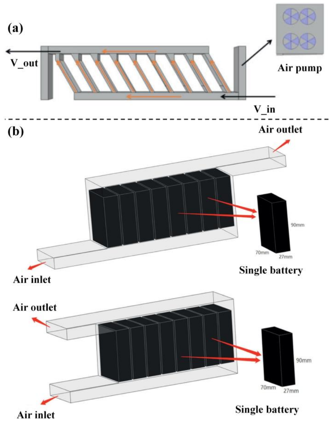
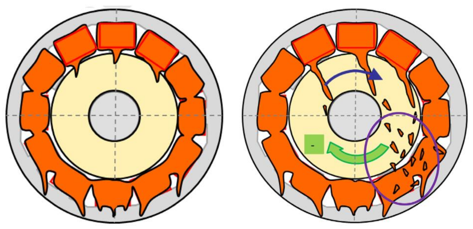
Efficient thermal management technologies are essential to prevent insulation failure, short circuits, demagnetization, and burn-out of electric motors, which can result in improved speed and torque. Various strategies exist to meet the demands of different heat flux levels. As heat generation mainly occurs in windings located in slots and rotors, thermal management technologies are primarily targeted toward them rather than lamination due to iron losses. To address different levels of heat flux, technologies such as natural air cooling, forced air cooling, indirect and direct liquid cooling, and hybrid methods that incorporate thermal conduction enhancement technologies such as thermal paste, heat pipes, and phase change materials are expected to be implemented. Figure 19 provides an overview of the thermal management technologies that have been studied, which will be discussed in detail in this section.

4.2.1. Air Cooling

Air convection cooling is a commonly used cooling method for small-to-middle-sized electric motors. The optimization of airflow paths inside or outside of the motor domain to maximize heat transfer has been studied extensively. Ribs or fins are commonly used for natural convection cooling outside of the motor, and their layouts are under optimization. For internal air cooling, a fan is used to circulate the air in the motor. The optimization of heat transfer in the air gap and airflow path is crucial to cooling performance. Kim et al. [162] developed a 3D lumped-parameter thermal network model for an air-cooled induction motor. The model predicted the temperature field of the motor and the flow characteristics of air with only a 2% deviation from the CFD model. Peng et al. [163] studied electric motor cooling with forced air convection and showed that the fin pitch ratio had a significant influence on the temperature of the winding. Kim et al. [164] introduced air-gap fans to the motor cooling, and various fan configurations were studied. The results indicated that the presence of a fan eliminated stagnant flow at both ends of the air gap and significantly increased the flow rate. This led to improvements in the heat transfer coefficients at the winding surface and air gap of up to 31% and 90%, respectively. Furthermore, the cooling performance of the rear fan was superior to that of the front fan, demonstrating the coupling effect of motor structure and airflow. A novel study introduced air into the motor through a hollow rotor [165], which significantly decreased the temperature of the magnet. However, due to the high speed of the rotor, the air may experience flow separation near the wall surface, and the pressure distribution is non-uniform. Special attention should be paid to the optimization of geometric parameters [166]. Although the design of motor cooling by air is a relatively mature technology, accurate predictions of heat transfer coefficients in the air gap and end space are challenging. Further research is expected to reveal these characteristics and maximize air cooling performance.

4.2.2. Liquid Cooling

Liquid cooling is currently the dominant thermal management system in electric motors due to its excellent heat transfer ability. From the perspective of the winding, liquid cooling can be divided into indirect and direct liquid cooling. In the former, the coolant does not come into direct contact with the winding, and its flow path typically involves jacket-like serpentine channels in the housing. Water is the most commonly used coolant, and numerous studies have been conducted on water jacket cooling, making it a mature technology in the motor industry. Satrustegui et al. [167] presented a lumped-parameter thermal network model and a CFD analysis for a water jacket cooling motor with different cooling duct topologies, including spiral, U-shaped (one duct), U-shaped (bifurcated), and axial. Design parameters for the water jacket, such as the position of cooling ducts and their geometric dimensions, are proposed therein (Figure 20). Wu et al. [168] proposed a smooth and spirally twisted channel for jacket cooling (Figure 20), which showed improved cooling performance and up to 10% lower average temperature. Ethylene glycol solution is also used as a coolant as it expands the temperature range of water cooling. Ali et al. [169] showed that an increase in the turns of the jacket channel, the volume fraction of ethylene glycol, and the flow Reynolds number were expected to benefit cooling performance. Oil is another coolant alternative, which is highly compatible with the lubrication system. Nategh et al. [170] investigated a novel housing-and-stator channel layout for motor cooling with oil. This structure extended the oil distribution and increased cooling performance compared to conventional jacket structures. The developed CFD model well predicted the experimental hot spots of the motor.
Cooling channels can be positioned within the slot to directly cool the winding. Rhebergen et al. [171] employed serpentine channels to achieve axial cooling in an electric motor. These cooling channels were situated atop the winding in each slot. The winding temperature was observed to decrease significantly by 65~90 °C, even when using a polymer composite with a thermal conductivity of only 2 W/(m∙K). The authors suggested that using materials with higher thermal conductivity could further enhance cooling performance.
Rahman et al. [172] examined direct slot winding cooling by utilizing triangular prism gaps among windings. Despite a 25% reduction in the filling ratio, the winding temperature decreased by approximately 60 °C, and the current density increased by 30%. In some instances, hollow conductors were also employed in motors, providing an internal coolant path. Chen et al. [173] detailed a cooling strategy using hollow conductors, with both computational fluid dynamics (CFD) and lumped-parameter thermal network models presented to analyze the cooling performance. The results indicated that, when coolant flowed within the hollow conductor, the winding temperature could be reduced by up to 33 °C compared to indirect cooling.
Wohlers et al. [174] introduced two tooth-coil winding designs. The winding was directly cooled by the coolant flowing through internal paths. The novel winding shape was found to homogenize current density at the winding cross-section. Furthermore, direct cooling was reported to achieve a fivefold increase in current density compared to water jacket cooling at equivalent heat loads.
Another significant heat source in motors is the end winding. Consequently, direct cooling of end windings also holds considerable promise. In contrast to slot windings, which are embedded within the slot, end windings are situated at each end of the motor. This arrangement allows for more thermal management techniques to be employed, given the increased space available.
Oil jet cooling and oil spray cooling have both been explored as cooling methods. Davin et al. [175] investigated oil cooling for end windings, with oil being ejected to each end of the winding as depicted in Figure 21. The results revealed that the oil flow rate had a more pronounced impact on cooling performance, whereas rotor speed primarily influenced the local temperature. For multi-jet cases, oil distribution was not affected by flow rate or rotor speed. Wang et al. [176] examined oil spray cooling for end winding thermal management, as shown in Figure 22. Their findings suggested that the presence of oil spray helped maintain the winding temperature within safe limits at higher heat loads across all tested scenarios. Additionally, the temperature distribution of the winding was more uniform at elevated flow rates and spray temperatures. Guechi et al. [177] performed both CFD modeling and experimental investigations on oil spray cooling for end windings. With oil spray, the high thermal conductivity of resin for windings was deemed less significant. Other spray cooling methods for windings also demonstrated exceptional temperature management performance [178].

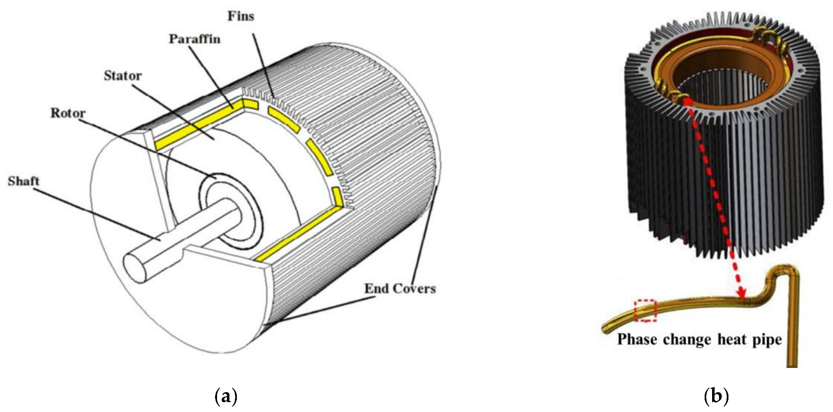
4.2.3. Other Solutions

In electric motors, the thermal conductivities of resin and lamination are typically much lower than that of the winding. Consequently, in addition to the research previously discussed, several innovative hybrid thermal management technologies have been proposed. These technologies combine advanced cooling and heat transfer enhancement methods to address extreme scenarios. The incorporation of thermal paste, potting materials, phase change materials, and heat pipes in electric motors has been reported and examined. As illustrated in Figure 23a, Wang et al. [179] proposed a novel motor casing with paraffin cavities and analyzed its performance. The findings suggested that the presence of paraffin cavities allowed the motor to operate 32.7% longer, with the peak temperature being 7.82 K lower at the same heat load. Additionally, it was shown that the paraffin melting temperature significantly affected cooling performance. A paraffin with a higher melting temperature, just below the heat-resistance temperature, was considered most beneficial for heat transfer. Incorporating heat pipes into the casing, as depicted in Figure 23b, Fang et al. [180] demonstrated that the stator temperature increase was substantially delayed by over 20%, and the peak temperature was also reduced for both straightly embedded and three-dimensional rounding heat pipe modules. Furthermore, the straightly embedded layout of heat pipes was expected to dissipate heat more effectively compared to three-dimensional rounding heat pipe modules. Building on this research, Sun et al. [181] noted that using potting material to fill the space between heat pipes and winding could further reduce the temperature increase. Similar studies also suggested that incorporating heat transfer enhancement materials could optimize the motor’s temperature distribution by more efficiently relocating heat.
Moreover, integrated thermal management strategies have been investigated to cool both the rotor and stator simultaneously. Coolant is typically introduced to a motor through a hollow rotor and then sprayed onto the stator (for winding and teeth cooling) and bearings via small holes. Park et al. [182] studied integrated thermal management technologies that used oil spraying from a hollow shaft for an in-wheel motor, as depicted in Figure 24a. This cooling method was found to reduce the winding temperature by up to 16% in tested cases. As motor speed increased, the cooling oil formed a thicker and more uniform oil film, resulting in improved heat transfer performance. At higher motor speeds, the contribution of oil film conduction dominated cooling performance, rather than that of oil spray heat transfer. It is important to note that the structure of the holes and their layout significantly impact the cooling performance of the oil spray system, as suggested by Lim et al. [183,184]. An oil spray cooling system was proposed, as shown in Figure 24b, in which the diameter and quantity of small holes for the bearing and winding were optimized. Both experimental testing and simulation results demonstrated that the system effectively maintained the winding temperature below 150 °C for the targeted motor.
Air cooling and water jacket cooling have been extensively employed in motor cooling systems and are anticipated to remain crucial for small-sized or low-heat-flux motors due to their well-established knowledge base and simple structures. However, as electric motors in electric vehicles face critical challenges, many advanced cooling technologies have been introduced to maintain temperatures within safe limits. As illustrated in Figure 25, jet impingement cooling, spray cooling, immersion cooling, and hybrid cooling strategies are expected to feature in new designs, with the industry rapidly shifting toward these approaches. To maximize fluid heat transfer capabilities, further advancements in cooling methods can be pursued, including phase change cooling with dielectric fluids and the incorporation of active cooling systems (such as high-efficiency TE cooling and VC cooling). Additionally, motor thermal management is a system-level design that also encompasses the thermal management of converters, batteries, and HVAC systems. The integration of these systems is expected to optimally utilize heat and create a more harmonious heat network for whole-vehicle-level systems.

5. Integrated Thermal Management System Solutions

An electric vehicle represents a complex thermal network at the system level. Considering the cabin environment, power battery, and electric motor subsystems discussed in this work, both heating and cooling are necessary, depending on specific scenarios. As a result, sustainable and efficient thermal management integration is essential and unavoidable for maximizing heat and cooling capacity within the system. Generally, heat sources include the power battery, motor, cabin environment, and ambient air, while heat sinks can be the power battery, cabin environment, and ambient air, as depicted in Figure 26. This section presents the integration concepts of thermal management technologies.
The majority of thermal management integration concepts focus on combining battery cooling and air conditioning systems. A branch of the air conditioning cooling loop is introduced to the battery through a series or parallel chillers. Shen et al. [185] proposed two dual-evaporator refrigeration systems for the thermal management of both the battery and cabin, connecting two evaporators in serial and parallel configurations. It was reported that both refrigeration systems had the same optimal filling ratio of refrigerant and effectively addressed the heat generated by the battery and cabin. Moreover, the COP and exergy efficiency of the series system were marginally higher than the parallel system under tested conditions. In a subsequent study, it was further noted that the system efficiently maintained temperature, and the temperature non-uniformity of the battery remained well below 3 °C [186]. Cen et al. [187] combined an air-cooling system with battery cooling. With the proposed active cooling, the battery temperature was maintained below 35 °C, even under extreme conditions. Additionally, using a fin-structured heat exchanger, the battery pack achieved good temperature uniformity of less than 4 °C. The configuration of the cooling exchanger was also found to greatly influence the temperature uniformity of the battery. Hamut et al. [188] proposed a hybrid system for air conditioning and battery cooling systems. The system exhibited excellent flexibility in addressing various operating and ambient conditions. Energy and exergy analyses were conducted to evaluate the system’s performance. It was demonstrated that the heat transfer process between the system and the ambient environment, as well as fluid friction, contributed to most of the irreversibility.
One approach to integrating the air conditioning and battery thermal management systems is to use heat from the battery to compensate for the heat of the air conditioner in both heating and cooling modes. Zou et al. [189] proposed an integrated system that included cabin air conditioning and a battery system. When the air conditioner operates in heating mode, the battery’s heat is dissipated to the air duct to preheat the mixed air, enhancing the air conditioner system’s performance. In the cooling mode, the battery’s heat may be discharged to the supply air, depending on the battery’s heat load. When the air conditioning system is off, the battery’s heat is dissipated by an external heat exchanger through natural air cooling. This system efficiently redistributed the heating and cooling loads of the air conditioning and battery systems. It was shown that the refrigerant volumetric flow rate increased and decreased with the battery heat in the cooling and heating modes, respectively. In a similar study, Zou et al. [190] found that a new branch of the battery chiller played a crucial role in cooling the battery, and without additional power input the cooling capacity increased by 20%. Han et al. [191] simulated an integrated system of vapor compression and battery cooling. Valves allowed the loop to operate in series cycles for heating and parallel cycles for heating and cooling modes. With the battery integration, the new system’s COP and heat capacity improved by 7.88% and 13.57% under tested conditions, respectively. The optimal injection pressure increased with the battery’s heat load. However, as the ambient temperature increased, the advantages of the integrated system diminished. Through exergy analysis, Zhang et al. [192] suggested that the compressor was the primary source of system exergy loss, accounting for 60% and 40% in cooling and heating modes, respectively. The integrated system’s advantages were more evident at lower compressor speeds, lower ambient temperatures, and higher airflow rates in the condenser.
A more comprehensive integrated approach combines the motor, battery, and air conditioning systems. Xu et al. [193] proposed a holistic integration of thermal management for electric vehicles, consisting of an air loop, a motor cooling loop, an air conditioning loop, a PEMC cooling/heating loop, and a battery cooling loop. These loops were connected to redistribute heat and cooling capacity accordingly. At steady state, the maximum outlet temperatures of the PEMC, motor, and air loop were shown to fall within safe temperature ranges. Additionally, with a novel PID control algorithm, the system effectively maintained lower temperatures, demonstrating the control strategy’s validity. Tian et al. [194] proposed another integrated model for the thermal management of the motor, cabin environment, and battery. The heat generated by the motor and converter was utilized in the air conditioning system to enhance both the heating and cooling cycles. It was reported that greater heat generation from the motor and converter, as well as lower condensation pressure, benefitted the system’s performance. Under the studied conditions, the system’s COP improved by a maximum of 13.8%. Furthermore, an economic analysis revealed that, with the newly proposed system, the annual cost decreased by at least 54.8% compared to using heaters alone. Table 2 presents the details of the proposed integrated systems.

6. Conclusions

The electric vehicle has drawn wide attention as it is expected to significantly decrease the carbon footprint in the transport sector. One of the most challenging technologies is the development of highly-efficient thermal management strategies to maintain a driver-friendly cabin environment and favorable temperature ranges of the battery and motor systems. To shed light on the upcoming upgrading, the latest thermal management technologies as well as innovative concepts targeted at electric vehicles are presented and critically reviewed in this paper. The main conclusions of this paper are as follows:
(1) The air conditioning system works in both cooling and heating models. The optimization of key components, including the compressor and heat exchangers, is very essential. The scroll compressor is widely applied in the industry. Technics, including the optimization of its design geometry, the introduction of scroll tip geometry, involvement of variable wall thicknesses, incorporating vapor injection/bypass holes, and adding innovative discharge ports are the most studied and effectively implemented. As for the heat exchanger, the ongoing optimization of the flow path for both the refrigerant and coolant is expected to improve the heat transfer performance of PHE, as well as the cycle efficiency. Meanwhile, R134a is currently the most used refrigerant in the air conditioning systems in vehicles; nevertheless, it will surely be replaced by more environmental-friendly ones, including natural refrigerants (such as HCs, CO2, ammonia, etc.). With the waste energy relocating in the vehicle, other cooling systems driven by heat (such as an absorption cooling system, ejector cooling system, adsorption cooling system, and even thermoelectric cooling system) may also be available in the near future.
(2) In terms of battery thermal management, this paper reviews the different cooling and heating methods as well as the thermal control performance of lithium-ion battery packs. In order to achieve higher cooling performance in BTM systems, there have been many studies related to geometric optimization such as air channels, cell configuration, and flow paths. The patterns of coolant flow paths are very vital to delivering remarkable temperature distribution control, and optimization will continue to be a hot topic. With the development of large-capacity, high-power, high-energy-density batteries, and the focus on the performance of electric vehicles under extreme temperature conditions, it is difficult for a single thermal management system to meet the needs of power batteries. Thermal management requirements and research on coupled systems based on multiple thermal management methods are expected to become a trend in the future.
(3) Various advanced thermal management technologies have also been proposed and studied for motor thermal management in electric vehicles. While liquid jacket cooling contributes to most commercial applications, spray cooling, jet impingement cooling, and immersion cooling with or without heat transfer enhancement methods (including thermal paste, heat pipe, PCM, etc.) are very attractive for higher current flux motors. Next-generation electric motors with higher torque, higher speed, and higher heat flux will surely involve more advanced cooling methods with phase change. There are already some commercial spray cooling designs for the winding available in the industry.
(4) The integration of the abovementioned thermal management technologies is inevitable in EVs. The insight concepts of integration cover air conditioning, battery, and motor, and some of them have proven to be effective and successful in the transport industry. The integration of BTM and AC systems is expected with higher technology readiness. The AC system is expected to provide the cooling or heating capacities to the BTM system in summer and winter scenarios, and vice versa. A higher integration would include the AC system, BTM system, and MTM system, within which the heat and cooling capacities are relocated as a whole thermal system to maximize energy utilization. Nevertheless, many of these technologies are still in the laboratory stage and waiting for further validation.
Despite diverse methods and their integration being available for thermal management in EVs, there are still some challenges that need to be tackled. As EVs are very compact, there is only limited space for the integration of thermal management technologies. The integration loop should avoid involving too many heat exchangers, as well as pumps as they will simultaneously produce noise. A high-profile control strategy is also needed to efficiently relocate the heat and energy. This involves advanced sensors to monitor key system parameters and algorithms to adjust the flow rate of the coolant, the pressure of the refrigerant, the power of the components, etc. To facilitate the commercial applications of the proposed integration concepts, solid economic analysis tools are also critically needed to balance the cost and performance. A more comprehensive analysis of the system-level integration of thermal management technologies would still be beneficial.

Author Contributions

Conceptualization, M.W. and D.D.; investigation and resources, Y.Z.; writing—original draft preparation, D.D. and Y.Z.; writing—review and editing, M.W. and X.W.; supervision, M.W.; funding acquisition, D.D. All authors have read and agreed to the published version of the manuscript.

Funding

This work was supported by the National Natural Science Foundation of China (No. 52202434).

Data Availability Statement

Data sharing not applicable.

Conflicts of Interest

The authors declare no conflict of interest.

References

  1. Zhang, X.; Li, Z.; Luo, L.; Fan, Y.; Du, Z. A review on thermal management of lithium-ion batteries for electric vehicles. Energy 2022, 238, 121652. [Google Scholar] [CrossRef]
  2. Backe, S.; Korpås, M.; Tomasgard, A. Heat and electric vehicle flexibility in the European power system: A case study of Norwegian energy communities. Int. J. Electr. Power Energy Syst. 2021, 125, 106479. [Google Scholar] [CrossRef]
  3. Zhao, G.; Wang, X.; Negnevitsky, M.; Zhang, H. A review of air-cooling battery thermal management systems for electric and hybrid electric vehicles. J. Power Sources 2021, 501, 230001. [Google Scholar] [CrossRef]
  4. Zhao, Y.; Dan, D.; Zheng, S.; Wei, M.; Xie, Y. A two-stage eco-cooling control strategy for electric vehicle thermal management system considering multi-source information fusion. Energy 2023, 267, 126606. [Google Scholar] [CrossRef]
  5. Lei, S.; Xin, S.; Liu, S. Separate and integrated thermal management solutions for electric vehicles: A review. J. Power Sources 2022, 550, 232133. [Google Scholar] [CrossRef]
  6. Wawzyniak, M.; Wiebelt, A. Thermal Management for Electrified Vehicles. MTZ Worldw. 2016, 77, 38–43. [Google Scholar] [CrossRef]
  7. Tan, L.; Yuan, Y. Computational fluid dynamics simulation and performance optimization of an electrical vehicle Air-conditioning system. Alex. Eng. J. 2022, 61, 315–328. [Google Scholar] [CrossRef]
  8. Yu, X.; Jiang, R.; Lu, G.; Liu, H.; Tong, Y.; Qian, G.; Huang, R.; Li, Z. A novel energy-economic-environmental evaluation model for heat pump air conditioners integrated with waste heat recovery in electric vehicles. Case Stud. Therm. Eng. 2023, 41, 102605. [Google Scholar] [CrossRef]
  9. Wu, J.; Zhou, G.; Wang, M. A comprehensive assessment of refrigerants for cabin heating and cooling on electric vehicles. Appl. Therm. Eng. 2020, 174, 115258. [Google Scholar] [CrossRef]
  10. Dan, D.; Li, W.; Zhang, Y.; Xie, Y. A quasi-dynamic model and thermal analysis for vapor chambers with multiple heat sources based on thermal resistance network model. Case Stud. Therm. Eng. 2022, 35, 102110. [Google Scholar] [CrossRef]
  11. Yu, Z.; Zhang, J.; Pan, W. A review of battery thermal management systems about heat pipe and phase change materials. J. Energy Storage 2023, 62, 106827. [Google Scholar] [CrossRef]
  12. Du, G.; Xu, W.; Zhu, J.; Huang, N. Power Loss and Thermal Analysis for High-Power High-Speed Permanent Magnet Machines. IEEE Trans. Ind. Electron. 2020, 67, 2722–2733. [Google Scholar] [CrossRef]
  13. Liang, K.; Wang, M.; Gao, C.; Dong, B.; Feng, C.; Zhou, X.; Liu, J. Advances and challenges of integrated thermal management technologies for pure electric vehicles. Sustain. Energy Technol. Assess. 2021, 46, 101319. [Google Scholar] [CrossRef]
  14. Yang, D.; Huo, Y.; Zhang, Q.; Xie, J.; Yang, Z. Recent advances on air heating system of cabin for pure electric vehicles: A review. Heliyon 2022, 8, e11032. [Google Scholar] [CrossRef]
  15. Lajunen, A.; Yang, Y.; Emadi, A. Review of Cabin Thermal Management for Electrified Passenger Vehicles. IEEE Trans. Veh. Technol. 2020, 69, 6025–6040. [Google Scholar] [CrossRef]
  16. Zhang, Z.; Wang, J.; Feng, X.; Chang, L.; Chen, Y.; Wang, X. The solutions to electric vehicle air conditioning systems: A review. Renew. Sustain. Energy Rev. 2018, 91, 443–463. [Google Scholar] [CrossRef]
  17. Shahid, S.; Agelin-Chaab, M. A review of thermal runaway prevention and mitigation strategies for lithium-ion batteries. Energy Convers. Manag. X 2022, 16, 100310. [Google Scholar] [CrossRef]
  18. Ghaeminezhad, N.; Wang, Z.; Ouyang, Q. A Review on lithium-ion battery thermal management system techniques: A control-oriented analysis. Appl. Therm. Eng. 2023, 219, 119497. [Google Scholar] [CrossRef]
  19. Wang, X.; Li, B.; Gerada, D.; Huang, K.; Stone, I.; Worrall, S.; Yan, Y. A critical review on thermal management technologies for motors in electric cars. Appl. Therm. Eng. 2022, 201, 117758. [Google Scholar] [CrossRef]
  20. Norin, F.; Wyon, D. Driver Vigilance—The Effects of Compartment Temperature; SAE: Warrendale, PA, USA, 1992. [Google Scholar] [CrossRef]
  21. Warey, A.; Kaushik, S.; Khalighi, B.; Cruse, M.; Venkatesan, G. Data-driven prediction of vehicle cabin thermal comfort: Using machine learning and high-fidelity simulation results. Int. J. Heat Mass Transf. 2020, 148, 119083. [Google Scholar] [CrossRef]
  22. Zou, H.; Tang, Z.; Yang, T.; Tian, C. Review of Research on Thermal Management Technology for Electric Vehicles. J. Refrig. 2022, 43, 15–27, 56. (In Chinese) [Google Scholar] [CrossRef]
  23. Xie, Y.; Ou, J.; Li, W.; Li, K.; Liu, J.; Liu, Z.; Zhou, D.; Li, J. An intelligent eco-heating control strategy for heat-pump air conditioning system of electric vehicles. Appl. Therm. Eng. 2022, 216, 119126. [Google Scholar] [CrossRef]
  24. Shin, H.; Park, S.; Kim, H.; Yang, I. Development of an integrated energy management strategy with cabin heating for plug-in hybrid electric vehicle. In Proceedings of the 2015 Tenth International Conference on Ecological Vehicles and Renewable Energies (EVER), Monte Carlo, Monaco, 31 March–2 April 2015; pp. 1–10. [Google Scholar]
  25. Kiss, T.; Lustbader, J.; Leighton, D. Modeling of an Electric Vehicle Thermal Management System in MATLAB/Simulink; SAE Technical Paper; SAE: Warrendale, PA, USA, 2015. [Google Scholar] [CrossRef] [Green Version]
  26. Piao, C.; Wang, W.; Liu, Z.; Wu, C.; Yuan, R. Research on vehicle cabin temperature and thermal comfort optimal control based on fuzzy PID. J. Phys. Conf. Ser. 2021, 1865, 032039. [Google Scholar] [CrossRef]
  27. Cvok, I.; Ratkovic, I.; Deur, J. Optimisation of Control Input Allocation Maps for Electric Vehicle Heat Pump-based Cabin Heating Systems. Energies 2020, 13, 5131. [Google Scholar] [CrossRef]
  28. Bernagozzi, M.; Georgoulas, A.; Miché, N.; Marengo, M. Heat pipes in battery thermal management systems for electric vehicles: A critical review. Appl. Therm. Eng. 2023, 219, 119495. [Google Scholar] [CrossRef]
  29. Youssef, R.; Hosen, M.S.; He, J.; Al-Saadi, M.; Van Mierlo, J.; Berecibar, M. Novel design optimization for passive cooling PCM assisted battery thermal management system in electric vehicles. Case Stud. Therm. Eng. 2022, 32, 101896. [Google Scholar] [CrossRef]
  30. Lander, L.; Kallitsis, E.; Hales, A.; Edge, J.S.; Korre, A.; Offer, G. Cost and carbon footprint reduction of electric vehicle lithium-ion batteries through efficient thermal management. Appl. Energy 2021, 289, 116737. [Google Scholar] [CrossRef]
  31. Mi, C.; Li, B.; Buck, D.; Ota, N. Advanced electro-thermal modeling of lithium-ion battery system for hybrid electric vehicle applications. In Proceedings of the 2007 IEEE Vehicle Power and Propulsion Conference, Arlington, TX, USA, 9–12 September 2007; pp. 107–111. [Google Scholar]
  32. Liu, P.; Wang, J.; Hicks-Garner, J.; Sherman, E.; Soukiazian, S.; Verbrugge, M.; Tataria, H.; Musser, J.; Finamore, P. Aging mechanisms of LiFePO4 batteries deduced by electrochemical and structural analyses. J. Electrochem. Soc. 2010, 157, A499. [Google Scholar] [CrossRef]
  33. Zhao, G.; Wang, X.; Negnevitsky, M. Connecting battery technologies for electric vehicles from battery materials to management. iScience 2022, 25, 103744. [Google Scholar] [CrossRef]
  34. Safdari, M.; Ahmadi, R.; Sadeghzadeh, S. Numerical and experimental investigation on electric vehicles battery thermal management under New European Driving Cycle. Appl. Energy 2022, 315, 119026. [Google Scholar] [CrossRef]
  35. Allen, J. Review of polymers in the prevention of thermal runaway in lithium-ion batteries. Energy Rep. 2020, 6, 217–224. [Google Scholar] [CrossRef]
  36. Pesaran, A.; Santhanagopalan, S.; Kim, G. Addressing the Impact of Temperature Extremes on Large Format Li-Ion Batteries for Vehicle Applications (Presentation); National Renewable Energy Lab.(NREL): Golden, CO, USA, 2013.
  37. Lu, M.; Zhang, X.; Ji, J.; Xu, X.; Zhang, Y. Research progress on power battery cooling technology for electric vehicles. J. Energy Storage 2020, 27, 101155. [Google Scholar] [CrossRef]
  38. Zhang, Q.; Wang, D.; Yang, B.; Cui, X.; Li, X. Electrochemical model of lithium-ion battery for wide frequency range applications. Electrochim. Acta 2020, 343, 136094. [Google Scholar] [CrossRef]
  39. Nejad, S.; Gladwin, D.T.; Stone, D.A. A systematic review of lumped-parameter equivalent circuit models for real-time estimation of lithium-ion battery states. J. Power Sources 2016, 316, 183–196. [Google Scholar] [CrossRef] [Green Version]
  40. Wang, Y.; Yang, D.; Zhang, X.; Chen, Z. Probability based remaining capacity estimation using data-driven and neural network model. J. Power Sources 2016, 315, 199–208. [Google Scholar] [CrossRef]
  41. Romero-Becerril, A.; Alvarez-Icaza, L. Comparison of discretization methods applied to the single-particle model of lithium-ion batteries. J. Power Sources 2011, 196, 10267–10279. [Google Scholar] [CrossRef]
  42. Doyle, M.; Fuller, T.F.; Newman, J. Modeling of Galvanostatic Charge and Discharge of the Lithium/Polymer/Insertion Cell. J. Electrochem. Soc. 1993, 140, 1526. [Google Scholar] [CrossRef]
  43. Han, X.; Ouyang, M.; Lu, L.; Li, J. Simplification of physics-based electrochemical model for lithium ion battery on electric vehicle. Part II: Pseudo-two-dimensional model simplification and state of charge estimation. J. Power Sources 2015, 278, 814–825. [Google Scholar] [CrossRef]
  44. Xu, X.; Tang, S.; Ren, H.; Han, X.; Wu, Y.; Lu, L.; Feng, X.; Yu, C.; Xie, J.; Ouyang, M.; et al. Joint state estimation of lithium-ion batteries combining improved equivalent circuit model with electrochemical mechanism and diffusion process. J. Energy Storage 2022, 56, 106135. [Google Scholar] [CrossRef]
  45. Yunlong, L.; Yingchun, L.; Haijing, Z.; Huichao, G. Analysis of factors influencing homogenization effect of microlens array in laser lighting system. In Proceedings of the International Conference on Laser, Optics and Optoelectronic Technology (LOPET 2021), Xi’an, China, 28–30 May 2021; p. 1188502. [Google Scholar]
  46. Wang, Q.-K.; He, Y.-J.; Shen, J.-N.; Ma, Z.-F.; Zhong, G.-B. A unified modeling framework for lithium-ion batteries: An artificial neural network based thermal coupled equivalent circuit model approach. Energy 2017, 138, 118–132. [Google Scholar] [CrossRef]
  47. Dong, G.; Zhang, X.; Zhang, C.; Chen, Z. A method for state of energy estimation of lithium-ion batteries based on neural network model. Energy 2015, 90, 879–888. [Google Scholar] [CrossRef]
  48. Li, S.; He, H.; Li, J. Big data driven lithium-ion battery modeling method based on SDAE-ELM algorithm and data pre-processing technology. Appl. Energy 2019, 242, 1259–1273. [Google Scholar] [CrossRef]
  49. Arbab, N.; Wang, W.; Lin, C.; Hearron, J.; Fahimi, B. Thermal Modeling and Analysis of a Double-Stator Switched Reluctance Motor. IEEE Trans. Energy Convers. 2015, 30, 1209–1217. [Google Scholar] [CrossRef]
  50. Ušakovs, I.; Mishkinis, D.; Galkin, I.A.; Bubovich, A.; Podgornovs, A. Experimental thermal characterization of the in-wheel electric motor with loop heat pipe thermal management system. Case Stud. Therm. Eng. 2023, 47, 103069. [Google Scholar] [CrossRef]
  51. Zhang, X.; Yang, Q.; Ma, M.; Lin, Z.; Yang, S. A Switched Reluctance Motor Torque Ripple Reduction Strategy With Deadbeat Current Control and Active Thermal Management. IEEE Trans. Veh. Technol. 2020, 69, 317–327. [Google Scholar] [CrossRef] [Green Version]
  52. Park, M.H.; Kim, S.C. Development and validation of lumped parameter thermal network model on rotational oil spray cooled motor for electric vehicles. Appl. Therm. Eng. 2023, 225, 120176. [Google Scholar] [CrossRef]
  53. Tikadar, A.; Johnston, D.; Kumar, N.; Joshi, Y.; Kumar, S. Comparison of electro-thermal performance of advanced cooling techniques for electric vehicle motors. Appl. Therm. Eng. 2021, 183, 116182. [Google Scholar] [CrossRef]
  54. Kim, S.; Lee, S.; Kang, D.G.; Kim, M.S. Motor cooling method using flow boiling of two-phase refrigerant and its analysis with lumped parameter thermal model. Int. J. Therm. Sci. 2023, 192, 108458. [Google Scholar] [CrossRef]
  55. Li, B.; Kuo, H.; Wang, X.; Chen, Y.; Wang, Y.; Gerada, D.; Worall, S.; Stone, I.; Yan, Y. Thermal Management of Electrified Propulsion System for Low-Carbon Vehicles. Automot. Innov. 2020, 3, 299–316. [Google Scholar] [CrossRef]
  56. Garud, K.S.; Hwang, S.-G.; Han, J.-W.; Lee, M.-Y. Performance characteristics of the direct spray oil cooling system for a driving motor of an electric vehicle. Int. J. Heat Mass Transf. 2022, 196, 123228. [Google Scholar] [CrossRef]
  57. Garud, K.S.; Lee, M.-Y. Grey relational based Taguchi analysis on heat transfer performances of direct oil spray cooling system for electric vehicle driving motor. Int. J. Heat Mass Transf. 2023, 201, 123596. [Google Scholar] [CrossRef]
  58. Park, J.; An, J.; Han, K.; Choi, H.-S.; Seouk Park, I. Enhancement of cooling performance in traction motor of electric vehicle using direct slot cooling method. Appl. Therm. Eng. 2022, 217, 119082. [Google Scholar] [CrossRef]
  59. Chang, M.; Lai, B.; Wang, H.; Bai, J.; Mao, Z. Comprehensive efficiency analysis of air-cooled vs water-cooled electric motor for unmanned aerial vehicle. Appl. Therm. Eng. 2023, 225, 120226. [Google Scholar] [CrossRef]
  60. Saleem, A.; Hyeon Park, M.; Ambreen, T.; Chul Kim, S. Optimization of oil flow distribution inside the in-wheel motor assembly of electric vehicles for improved thermal performance. Appl. Therm. Eng. 2022, 201, 117753. [Google Scholar] [CrossRef]
  61. Shazly, J.; Wahsh, S.; Yassin, A. Thermal modeling of an AFPMSM: A review. J. Electr. Syst. Inf. Technol. 2015, 2, 18–26. [Google Scholar] [CrossRef] [Green Version]
  62. Sciascera, C.; Giangrande, P.; Papini, L.; Gerada, C.; Galea, M. Analytical Thermal Model for Fast Stator Winding Temperature Prediction. IEEE Trans. Ind. Electron. 2017, 64, 6116–6126. [Google Scholar] [CrossRef]
  63. Huang, X.; Li, K.; Xie, Y.; Liu, B.; Liu, J.; Liu, Z.; Mou, L. A novel multistage constant compressor speed control strategy of electric vehicle air conditioning system based on genetic algorithm. Energy 2022, 241, 122903. [Google Scholar] [CrossRef]
  64. Göltz, S.; Sawodny, O. Design and comparison of model-based controllers for an automotive air conditioning system in an electric vehicle. Control Eng. Pract. 2023, 130, 105376. [Google Scholar] [CrossRef]
  65. Power, P.; Evaporator, E.; Energy, E.; Condenser, C.; Rate, Q.H.F. Simulative Comparison of Conventional and Secondary Loop Automotive Refrigeration Systems. In Proceedings of the Vehicle Thermal Management Systems Conference, Nottingham, UK, 10–13 May 2015; pp. 511–523. [Google Scholar]
  66. Zhang, L.; Jiang, Y.; Dong, J.; Yao, Y. Advances in vapor compression air source heat pump system in cold regions: A review. Renew. Sustain. Energy Rev. 2018, 81, 353–365. [Google Scholar] [CrossRef]
  67. Zhao, R.; Li, W.; Zhuge, W. Unsteady characteristic and flow mechanism of a scroll compressor with novel discharge port for electric vehicle air conditioning. Int. J. Refrig. 2020, 118, 403–414. [Google Scholar] [CrossRef]
  68. Lemort, V.; Quoilin, S.; Cuevas, C.; Lebrun, J. Testing and modeling a scroll expander integrated into an Organic Rankine Cycle. Appl. Therm. Eng. 2009, 29, 3094–3102. [Google Scholar] [CrossRef] [Green Version]
  69. Ishii, N.; Sakai, M.; Sano, K.; Yamamoto, S.; Otokura, T. A fundamental optimum design for high mechanical and volumetric efficiency of compact scroll compressors. In Proceedings of the International Compressor Engineering Conference, West Lafayette, IN, USA, 23–26 July 1996. [Google Scholar]
  70. Tateishi, T.; Sato, H.; Kobayashi, H.; Mizuno, H. Development of high performance 3d scroll compressor. In Proceedings of the International Compressor Engineering Conference, Lafayette, IN, USA, 17–20 July 2006. [Google Scholar]
  71. Clemente, S.; Micheli, D.; Reini, M.; Taccani, R. Energy efficiency analysis of Organic Rankine Cycles with scroll expanders for cogenerative applications. Appl. Energy 2012, 97, 792–801. [Google Scholar] [CrossRef]
  72. Emhardt, S.; Tian, G.; Chew, J. A review of scroll expander geometries and their performance. Appl. Therm. Eng. 2018, 141, 1020–1034. [Google Scholar] [CrossRef]
  73. Zheng, S.; Wei, M.; Zhou, Y.; Hu, C.; Song, P. Tangential leakage flow control with seal-grooves on the static scroll of a CO2 scroll compressor. Appl. Therm. Eng. 2022, 208, 118213. [Google Scholar] [CrossRef]
  74. Blunier, B.; Cirrincione, G.; Hervé, Y.; Miraoui, A. A new analytical and dynamical model of a scroll compressor with experimental validation. Int. J. Refrig. 2009, 32, 874–891. [Google Scholar] [CrossRef]
  75. Bell, I.H.; Groll, E.A.; Braun, J.E.; King, G.B.; Horton, W.T. Optimization of a scroll compressor for liquid flooding. Int. J. Refrig. 2012, 35, 1901–1913. [Google Scholar] [CrossRef] [Green Version]
  76. Hirano, T.; Hagimoto, K.; Maeda, M. Study on scroll profile for scroll fluid machines. Trans. Jpn. Soc. Refrig. Air Cond. Eng. 2011, 8, 53–64. [Google Scholar]
  77. Bin, P.; Lemort, V.; Legros, A.; Hongsheng, Z.; Haifeng, G. Variable thickness scroll compressor performance analysis—Part I: Geometric and thermodynamic modeling. Proc. Inst. Mech. Eng. Part E J. Process Mech. Eng. 2016, 231, 633–640. [Google Scholar] [CrossRef]
  78. Emhardt, S.; Song, P.; Tian, G.; Chew, J.; Wei, M. CFD analysis of variable wall thickness scroll expander integrated into small scale ORC systems. Energy Procedia 2019, 158, 2272–2277. [Google Scholar] [CrossRef]
  79. Emhardt, S.; Tian, G.; Song, P.; Chew, J.; Wei, M. CFD analysis of the influence of variable wall thickness on the aerodynamic performance of small scale ORC scroll expanders. Energy 2022, 244, 122586. [Google Scholar] [CrossRef]
  80. Qin, F.; Xue, Q.; Albarracin Velez, G.M.; Zhang, G.; Zou, H.; Tian, C. Experimental investigation on heating performance of heat pump for electric vehicles at −20 °C ambient temperature. Energy Convers. Manag. 2015, 102, 39–49. [Google Scholar] [CrossRef] [Green Version]
  81. Zhang, D.; Li, J.; Nan, J.; Wang, L. Thermal performance prediction and analysis on the economized vapor injection air-source heat pump in cold climate region of China. Sustain. Energy Technol. Assess. 2016, 18, 127–133. [Google Scholar] [CrossRef]
  82. Zhang, X.; Zhang, B.; Cao, J.; Su, L.; Li, K. Numerical investigation on the performance and vapor injection process of a scroll compressor with different injection features. Appl. Therm. Eng. 2022, 217, 119061. [Google Scholar] [CrossRef]
  83. Kim, D.; Jeon, Y.; Jang, D.S.; Kim, Y. Performance comparison among two-phase, liquid, and vapor injection heat pumps with a scroll compressor using R410A. Appl. Therm. Eng. 2018, 137, 193–202. [Google Scholar] [CrossRef]
  84. Park, Y.; Kim, J.; Oh, J.; Han, U.; Lee, H. Multi-objective optimization of an offset strip fin heat exchanger for waste heat recovery in electric vehicles. Appl. Therm. Eng. 2023, 228, 120533. [Google Scholar] [CrossRef]
  85. Samiolo, M.; Verdin, P.G. Numerical modelling of a finless heat exchanger layout for electric vehicle application. Appl. Therm. Eng. 2022, 211, 118506. [Google Scholar] [CrossRef]
  86. Prabakaran, R.; Salman, M.; Lee, D.; Kim, S.C. Condensation of R1234yf in a plate heat exchanger with an offset strip fin flow structure for electric vehicle heat pumps. Int. Commun. Heat Mass Transf. 2023, 143, 106699. [Google Scholar] [CrossRef]
  87. Meng, L.; Liu, J.; Bi, J.; Özdemir, E.D.; Aksel, M.H. Multi-objective optimization of plate heat exchanger for commercial electric vehicle based on genetic algorithm. Case Stud. Therm. Eng. 2023, 41, 102629. [Google Scholar] [CrossRef]
  88. Mahvi, A.J.; Boyina, K.; Musser, A.; Elbel, S.; Miljkovic, N. Superhydrophobic heat exchangers delay frost formation and enhance efficency of electric vehicle heat pumps. Int. J. Heat Mass Transf. 2021, 172, 121162. [Google Scholar] [CrossRef]
  89. Lee, J.; Lee, K.-S. Flow characteristics and thermal performance in chevron type plate heat exchangers. Int. J. Heat Mass Transf. 2014, 78, 699–706. [Google Scholar] [CrossRef]
  90. Han, D.-H.; Lee, K.-J.; Kim, Y.-H. Experiments on the characteristics of evaporation of R410A in brazed plate heat exchangers with different geometric configurations. Appl. Therm. Eng. 2003, 23, 1209–1225. [Google Scholar] [CrossRef]
  91. Würfel, R.; Ostrowski, N. Experimental investigations of heat transfer and pressure drop during the condensation process within plate heat exchangers of the herringbone-type. Int. J. Therm. Sci. 2004, 43, 59–68. [Google Scholar] [CrossRef]
  92. Liu, Z.; Chen, Z.; Li, W.; Ding, Z.; Xu, Z. Composite Fouling Characteristics on Ni-P-PTFE Nanocomposite Surface in Corrugated Plate Heat Exchanger. Heat Transf. Eng. 2021, 42, 1877–1888. [Google Scholar] [CrossRef]
  93. Lee, J.; Lee, K.-S. Friction and Colburn factor correlations and shape optimization of chevron-type plate heat exchangers. Appl. Therm. Eng. 2015, 89, 62–69. [Google Scholar] [CrossRef]
  94. Zhang, Y.; Jiang, C.; Yang, Z.; Zhang, Y.; Bai, B. Numerical study on heat transfer enhancement in capsule-type plate heat exchangers. Appl. Therm. Eng. 2016, 108, 1237–1242. [Google Scholar] [CrossRef]
  95. Durmuş, A.; Benli, H.; Kurtbaş, İ.; Gül, H. Investigation of heat transfer and pressure drop in plate heat exchangers having different surface profiles. Int. J. Heat Mass Transf. 2009, 52, 1451–1457. [Google Scholar] [CrossRef]
  96. Nguyen, D.H.; Kweon, B.; Kwon, J.-S.; Kim, T.; Wongwises, S.; Ahn, H.S. Numerical study on novel airfoil corrugated plate heat exchanger: A comparison with commercial type and geometrical parameter analysis. Int. J. Heat Mass Transf. 2022, 195, 123119. [Google Scholar] [CrossRef]
  97. Yao, Y.; Ding, J.; Zhang, Y.; Wang, W.; Lu, J. Heat transfer performance of pillow plate heat exchanger with molten salt and supercritical carbon dioxide. Int. J. Heat Mass Transf. 2022, 183, 122211. [Google Scholar] [CrossRef]
  98. Wang, D.; Zhang, H.; Wang, G.; Yuan, H.; Peng, X. Experimental and numerical study on the heat transfer and flow characteristics of convex plate heat exchanger based on multi-objective optimization. Int. J. Heat Mass Transf. 2023, 202, 123755. [Google Scholar] [CrossRef]
  99. Habib, T.; Kristiansen, J.N.; Rana, M.B.; Ritala, P. Revisiting the role of modular innovation in technological radicalness and architectural change of products: The case of Tesla X and Roomba. Technovation 2020, 98, 102163. [Google Scholar] [CrossRef]
  100. Mancini, N.; Mardall, J.; Kopitz, J.; O’Donnell, C.R.; Hanks, D.F.; Li, H. Optimal Source Electric Vehicle Heat Pump with Extreme Temperature Heating Capability and Efficient Thermal Preconditioning. U.S. Patent 10,967,702, 6 April 2021. [Google Scholar]
  101. Zhang, Z.; Liang, T.; Yang, L.; Yongjian, F.U. Integrated Expansion Kettle for Electric Car, and Electric Car. CN 201910822053.4, 11 March 2021. [Google Scholar]
  102. Li, S.; Xu, M.; Jin, W.; Ye, M.; Zhou, Z. Integrated Valve Module. 215063015U, 7 December 2021. [Google Scholar]
  103. Zhang, Z.; Wang, D.; Zhang, C.; Chen, J. Electric vehicle range extension strategies based on improved AC system in cold climate—A review. Int. J. Refrig. 2018, 88, 141–150. [Google Scholar] [CrossRef]
  104. Bellocchi, S.; Leo Guizzi, G.; Manno, M.; Salvatori, M.; Zaccagnini, A. Reversible heat pump HVAC system with regenerative heat exchanger for electric vehicles: Analysis of its impact on driving range. Appl. Therm. Eng. 2018, 129, 290–305. [Google Scholar] [CrossRef] [Green Version]
  105. Feng, L.; Hrnjak, P. Experimental Study of an Air Conditioning-Heat Pump System for Electric Vehicles; SAE Technical Paper; SAE: Warrendale, PA, USA, 2016; Volume 9. [Google Scholar]
  106. Ning, Q.; He, G.; Xiong, G.; Sun, W.; Song, H. Operation strategy and performance investigation of a high-efficiency multifunctional two-stage vapor compression heat pump air conditioning system for electric vehicles in severe cold regions. Sustain. Energy Technol. Assess. 2021, 48, 101617. [Google Scholar] [CrossRef]
  107. Yu, T.; Wang, B.; Li, X.; Shi, W. Performance analysis and operation strategy of a dual-evaporation temperature heat pump system for electric vehicles in winter. Appl. Therm. Eng. 2023, 219, 119594. [Google Scholar] [CrossRef]
  108. Li, W.; Liu, Y.; Liu, R.; Wang, D.; Shi, J.; Yu, Z.; Cheng, L.; Chen, J. Performance evaluation of secondary loop low-temperature heat pump system for frost prevention in electric vehicles. Appl. Therm. Eng. 2021, 182, 115615. [Google Scholar] [CrossRef]
  109. Nasr, M.R.; Fauchoux, M.; Besant, R.W.; Simonson, C.J. A review of frosting in air-to-air energy exchangers. Renew. Sustain. Energy Rev. 2014, 30, 538–554. [Google Scholar] [CrossRef]
  110. Kim, K.; Kim, M.-H.; Kim, D.R.; Lee, K.-S. Thermal performance of microchannel heat exchangers according to the design parameters under the frosting conditions. Int. J. Heat Mass Transf. 2014, 71, 626–632. [Google Scholar] [CrossRef]
  111. Hu, Y.; Yuill, D.P.; Ebrahimifakhar, A. The effects of outdoor air-side fouling on frost growth and heat transfer characteristics of a microchannel heat exchanger: An experimental study. Int. J. Heat Mass Transf. 2020, 151, 119423. [Google Scholar] [CrossRef]
  112. Liu, C.; Guo, X.M.; Yang, B. Experimental Study on the Defrost Characteristics of an Air Source Heat Pump Unit with Split Fin-tube Heat Exchangers. In Proceedings of the 2010 Asia-Pacific Power and Energy Engineering Conference, Chengdu, China, 28–31 March 2010; pp. 1–5. [Google Scholar]
  113. Li, K.; Xia, D.; Luo, S.; Zhao, Y.; Tu, R.; Zhou, X.; Zhang, H.; Su, L. An experimental investigation on the frosting and defrosting process of an outdoor heat exchanger in an air conditioning heat pump system for electric vehicles. Appl. Therm. Eng. 2022, 201, 117766. [Google Scholar] [CrossRef]
  114. Westhaeuser, J.; Schatz, H.; Albrecht, J.-C.; Tegethoff, W.; Lemke, N.; Koehler, J. Analysis of cyclic frosting and defrosting of a vehicle heat pump. Int. J. Refrig. 2023. [Google Scholar] [CrossRef]
  115. Liu, N.; Cui, Q.; Li, H.; Li, K.; Fang, Y.; Su, L.; Zhang, H.; Shan, X.; Jin, X. Investigating the performance optimization of an outdoor condenser–evaporator for an electric vehicle heat pump system. Energy Rep. 2021, 7, 5130–5140. [Google Scholar] [CrossRef]
  116. Li, K.; Xia, D.; Bao, J.; Luo, S.; Zhang, H.; Liu, N.; Su, L.; Sheng, L. Investigation on reverse cycle defrosting strategy of an outdoor heat exchanger in air conditioning heat pump system for electric vehicles. Case Stud. Therm. Eng. 2021, 27, 101281. [Google Scholar] [CrossRef]
  117. Chen, J.; Wu, J.; He, J.; Guo, Z. A novel defrosting initiating strategy for automotive air conditioner heat pumps based on frost thickness growth prediction. Int. J. Refrig. 2022, 134, 242–252. [Google Scholar] [CrossRef]
  118. Li, Z.; Liang, K.; Jiang, H. Experimental study of R1234yf as a drop-in replacement for R134a in an oil-free refrigeration system. Appl. Therm. Eng. 2019, 153, 646–654. [Google Scholar] [CrossRef]
  119. Li, W.; Liu, R.; Liu, Y.; Wang, D.; Shi, J.; Chen, J. Performance evaluation of R1234yf heat pump system for an electric vehicle in cold climate. Int. J. Refrig. 2020, 115, 117–125. [Google Scholar] [CrossRef]
  120. Meng, Z.; Zhang, H.; Lei, M.; Qin, Y.; Qiu, J. Performance of low GWP R1234yf/R134a mixture asa replacement for R134a in automotive air conditioning systems. Int. J. Heat Mass Transf. 2018, 116, 362–370. [Google Scholar] [CrossRef]
  121. Kandhaswamy, K.; Periasamy, S.; Mayilsamy, S.; Thangavel, S. Experimental investigations on automobile air conditioners working with R134a and R290/R600a as an alternative. Therm. Sci. 2017, 21, 515–522. [Google Scholar] [CrossRef] [Green Version]
  122. Huang, Y.; Wu, X.; Jing, J. Research on the electric vehicle heat pump air conditioning system based on R290 refrigerant. Energy Rep. 2022, 8, 447–455. [Google Scholar] [CrossRef]
  123. Liu, C.; Zhang, Y.; Gao, T.; Shi, J.; Chen, J.; Wang, T.; Pan, L. Performance evaluation of propane heat pump system for electric vehicle in cold climate. Int. J. Refrig. 2018, 95, 51–60. [Google Scholar] [CrossRef]
  124. Liu, B.; Yang, Z.; Zhang, Y.; Lv, Z.; Chen, Y.; Chen, S. Evaluation of a low-GWP and nonflammable blend as a new alternative for R134a in the heat pump system. Int. J. Refrig. 2022, 143, 1–10. [Google Scholar] [CrossRef]
  125. Yu, B.; Yang, J.; Wang, D.; Shi, J.; Guo, Z.; Chen, J. Experimental energetic analysis of CO2/R41 blends in automobile air-conditioning and heat pump systems. Appl. Energy 2019, 239, 1142–1153. [Google Scholar] [CrossRef]
  126. Mansour, S.; Jalali, A.; Ashjaee, M.; Houshfar, E. Multi-objective optimization of a sandwich rectangular-channel liquid cooling plate battery thermal management system: A deep-learning approach. Energy Convers. Manag. 2023, 290, 117200. [Google Scholar] [CrossRef]
  127. Ranjbaran, Y.S.; Shojaeefard, M.H.; Molaeimanesh, G.R. Thermal performance enhancement of a passive battery thermal management system based on phase change material using cold air passageways for lithium batteries. J. Energy Storage 2023, 68, 107744. [Google Scholar] [CrossRef]
  128. Weragoda, D.M.; Tian, G.; Burkitbayev, A.; Lo, K.-H.; Zhang, T. A comprehensive review on heat pipe based battery thermal management systems. Appl. Therm. Eng. 2023, 224, 120070. [Google Scholar] [CrossRef]
  129. Ebbs-Picken, T.; Da Silva, C.M.; Amon, C.H. Design optimization methodologies applied to battery thermal management systems: A review. J. Energy Storage 2023, 67, 107460. [Google Scholar] [CrossRef]
  130. Zhou, Z.; Chen, S.; Luo, M.; Du, W.; Wu, Y.; Yu, Y. Effect of mechanical vibration on phase change material based thermal management system for a cylindrical lithium-ion battery at high ambient temperature and high discharge rate. Int. J. Heat Mass Transf. 2023, 211, 124255. [Google Scholar] [CrossRef]
  131. Xiong, X.; Wang, Z.; Fan, Y.; Wang, H. Numerical analysis of cylindrical lithium-ion battery thermal management system based on bionic flow channel structure. Therm. Sci. Eng. Prog. 2023, 42, 101879. [Google Scholar] [CrossRef]
  132. Nazar, M.W.; Iqbal, N.; Ali, M.; Nazir, H.; Amjad, M.Z.B. Thermal management of Li-ion battery by using active and passive cooling method. J. Energy Storage 2023, 61, 106800. [Google Scholar] [CrossRef]
  133. Li, A.; Weng, J.; Yuen, A.C.Y.; Wang, W.; Liu, H.; Lee, E.W.M.; Wang, J.; Kook, S.; Yeoh, G.H. Machine learning assisted advanced battery thermal management system: A state-of-the-art review. J. Energy Storage 2023, 60, 106688. [Google Scholar] [CrossRef]
  134. Sahin, R.C.; Gocmen, S.; Cetkin, E. Thermal management system for air-cooled battery packs with flow-disturbing structures. J. Power Sources 2022, 551, 232214. [Google Scholar] [CrossRef]
  135. Shen, X.; Cai, T.; He, C.; Yang, Y.; Chen, M. Thermal analysis of modified Z-shaped air-cooled battery thermal management system for electric vehicles. J. Energy Storage 2023, 58, 106356. [Google Scholar] [CrossRef]
  136. Oyewola, O.M.; Awonusi, A.A.; Ismail, O.S. Design optimization of Air-Cooled Li-ion battery thermal management system with Step-like divergence plenum for electric vehicles. Alex. Eng. J. 2023, 71, 631–644. [Google Scholar] [CrossRef]
  137. Yang, C.; Xi, H.; Wang, M. Structure optimization of air cooling battery thermal management system based on lithium-ion battery. J. Energy Storage 2023, 59, 106538. [Google Scholar] [CrossRef]
  138. Luo, L.; Liu, Y.; Liao, Z.; Zhong, J. Optimal structure design and heat transfer characteristic analysis of X-type air-cooled battery thermal management system. J. Energy Storage 2023, 67, 107681. [Google Scholar] [CrossRef]
  139. Abdulrasool Hasan, H.; Togun, H.; M Abed, A.; I Mohammed, H.; Biswas, N. A novel air-cooled Li-ion battery (LIB) array thermal management system—A numerical analysis. Int. J. Therm. Sci. 2023, 190, 108327. [Google Scholar] [CrossRef]
  140. Li, W.; Wang, N.; Garg, A.; Gao, L. Multi-objective optimization of an air cooling battery thermal management system considering battery degradation and parasitic power loss. J. Energy Storage 2023, 58, 106382. [Google Scholar] [CrossRef]
  141. Wang, C.; Xu, J.; Wang, M.; Xi, H. Experimental investigation on reciprocating air-cooling strategy of battery thermal management system. J. Energy Storage 2023, 58, 106406. [Google Scholar] [CrossRef]
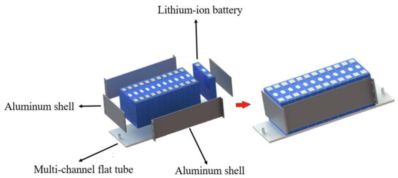
  142. Ren, R.; Zhao, Y.; Diao, Y.; Liang, L. Experimental study on the bottom liquid cooling thermal management system for lithium-ion battery based on multichannel flat tube. Appl. Therm. Eng. 2023, 219, 119636. [Google Scholar] [CrossRef]
  143. Zhao, D.; Lei, Z.; An, C. Research on battery thermal management system based on liquid cooling plate with honeycomb-like flow channel. Appl. Therm. Eng. 2023, 218, 119324. [Google Scholar] [CrossRef]
  144. Sheng, L.; Su, L.; Zhang, H.; Li, K.; Fang, Y.; Ye, W.; Fang, Y. Numerical investigation on a lithium ion battery thermal management utilizing a serpentine-channel liquid cooling plate exchanger. Int. J. Heat Mass Transf. 2019, 141, 658–668. [Google Scholar] [CrossRef]
  145. Xie, L.; Huang, Y.; Lai, H. Coupled prediction model of liquid-cooling based thermal management system for cylindrical lithium-ion module. Appl. Therm. Eng. 2020, 178, 115599. [Google Scholar] [CrossRef]
  146. Li, W.; Garg, A.; Xiao, M.; Gao, L. Optimization for Liquid Cooling Cylindrical Battery Thermal Management System Based on Gaussian Process Model. J. Therm. Sci. Eng. Appl. 2020, 13, 021015. [Google Scholar] [CrossRef]
  147. Yang, H.; Wang, Z.; Li, M.; Ren, F.; Feng, Y. A manifold channel liquid cooling system with low-cost and high temperature uniformity for lithium-ion battery pack thermal management. Therm. Sci. Eng. Prog. 2023, 41, 101857. [Google Scholar] [CrossRef]
  148. He, P.; Lu, H.; Fan, Y.; Ruan, H.; Wang, C.; Zhu, Y. Numerical investigation on a lithium-ion battery thermal management system utilizing a double-layered I-shaped channel liquid cooling plate exchanger. Int. J. Therm. Sci. 2023, 187, 108200. [Google Scholar] [CrossRef]
  149. Xie, J.; Liu, X.; Zhang, G.; Yang, X. A novel strategy to optimize the liquid cooling plates for battery thermal management by precisely tailoring the internal structure of the flow channels. Int. J. Therm. Sci. 2023, 184, 107877. [Google Scholar] [CrossRef]
  150. Wang, Z.; Wang, Y.; Xie, Z.; Li, H.; Peng, W. Parametric investigation on the performance of a direct evaporation cooling battery thermal management system. Int. J. Heat Mass Transf. 2022, 189, 122685. [Google Scholar] [CrossRef]
  151. Wu, W.; Yang, X.; Zhang, G.; Ke, X.; Wang, Z.; Situ, W.; Li, X.; Zhang, J. An experimental study of thermal management system using copper mesh-enhanced composite phase change materials for power battery pack. Energy 2016, 113, 909–916. [Google Scholar] [CrossRef]
  152. Zhou, D.; Luo, Y.; Bi, C.; Li, X.; Deng, J.; Yang, W.; Li, C. Experimental and simulative investigation on battery thermal management system with structural optimization of composite phase change material. J. Energy Storage 2023, 60, 106613. [Google Scholar] [CrossRef]
  153. Yan, J.; Li, K.; Chen, H.; Wang, Q.; Sun, J. Experimental study on the application of phase change material in the dynamic cycling of battery pack system. Energy Convers. Manag. 2016, 128, 12–19. [Google Scholar] [CrossRef]
  154. Xin, S.; Wang, C.; Xi, H. Thermal management scheme and optimization of cylindrical lithium-ion battery pack based on air cooling and liquid cooling. Appl. Therm. Eng. 2023, 224, 120100. [Google Scholar] [CrossRef]
  155. Wu, X.; Wang, K.; Chang, Z.; Chen, Y.; Cao, S.; Lv, C.; Liu, H.; Wang, Y. Experimental and numerical study on hybrid battery thermal management system combining liquid cooling with phase change materials. Int. Commun. Heat Mass Transf. 2022, 139, 106480. [Google Scholar] [CrossRef]
  156. Yao, M.; Gan, Y.; Liang, J.; Dong, D.; Ma, L.; Liu, J.; Luo, Q.; Li, Y. Performance simulation of a heat pipe and refrigerant-based lithium-ion battery thermal management system coupled with electric vehicle air-conditioning. Appl. Therm. Eng. 2021, 191, 116878. [Google Scholar] [CrossRef]
  157. Shabgard, H.; Allen, M.J.; Sharifi, N.; Benn, S.P.; Faghri, A.; Bergman, T.L. Heat pipe heat exchangers and heat sinks: Opportunities, challenges, applications, analysis, and state of the art. Int. J. Heat Mass Transf. 2015, 89, 138–158. [Google Scholar] [CrossRef]
  158. Ma, Y.; Ding, H.; Mou, H.; Gao, J. Battery thermal management strategy for electric vehicles based on nonlinear model predictive control. Measurement 2021, 186, 110115. [Google Scholar] [CrossRef]
  159. Ma, Y.; Ding, H.; Liu, Y.; Gao, J. Battery thermal management of intelligent-connected electric vehicles at low temperature based on NMPC. Energy 2022, 244, 122571. [Google Scholar] [CrossRef]
  160. Zhu, C.; Lu, F.; Zhang, H.; Sun, J.; Mi, C.C. A Real-Time Battery Thermal Management Strategy for Connected and Automated Hybrid Electric Vehicles (CAHEVs) Based on Iterative Dynamic Programming. IEEE Trans. Veh. Technol. 2018, 67, 8077–8084. [Google Scholar] [CrossRef]
  161. Broatch, A.; Pla, B.; Bares, P.; Perin, A. Leveraging look-ahead information for optimal battery thermal management. Appl. Therm. Eng. 2023, 220, 119685. [Google Scholar] [CrossRef]
  162. Kim, C.; Lee, K.-S. Thermal nexus model for the thermal characteristic analysis of an open-type air-cooled induction motor. Appl. Therm. Eng. 2017, 112, 1108–1116. [Google Scholar] [CrossRef]
  163. Peng, H.S.; Lai, F.H.; Iop. Investigation of Parameters Affecting Heat Transfer and Fluid Flow of a TEFC Electric Motor by Using Taguchi Method. IOP Conf. Ser. Mater. Sci. Eng. 2019, 491, 012021. [Google Scholar] [CrossRef]
  164. Kim, C.; Lee, K.S.; Yook, S.J. Effect of air-gap fans on cooling of windings in a large-capacity, high-speed induction motor. Appl. Therm. Eng. 2016, 100, 658–667. [Google Scholar] [CrossRef]
  165. Jaeger, M.; Ruf, A.; Hameyer, K.; Grosse-von Tongeln, T. Thermal Analysis of an Electrical Traction Motor with an Air Cooled Rotor. In Proceedings of the 2018 IEEE Transportation and Electrification Conference and Expo (ITEC), Bangkok, Thailand, 6–9 June 2018; pp. 467–470. [Google Scholar]
  166. Kim, M.S.; Lee, K.S.; Um, S. Numerical investigation and optimization of the thermal performance of a brushless DC motor. Int. J. Heat Mass Transf. 2009, 52, 1589–1599. [Google Scholar] [CrossRef]
  167. Satrustegui, M.; Martinez-Iturralde, M.; Ramos, J.C.; Gonzalez, P.; Astarbe, G.; Elosegui, I. Design criteria for water cooled systems of induction machines. Appl. Therm. Eng. 2017, 114, 1018–1028. [Google Scholar] [CrossRef]
  168. Wu, P.S.; Hsieh, M.-F.; Cai, W.L.; Liu, J.H.; Huang, Y.T.; Caceres, J.F.; Chang, S.W. Heat Transfer and Thermal Management of Interior Permanent Magnet Synchronous Electric Motor. Inventions 2019, 4, 69. [Google Scholar] [CrossRef] [Green Version]
  169. Deriszadeh, A.; de Monte, F.; Villani, M.; Di Leonardo, L. Hydrothermal Performance of Ethylene Glycol and Water Mixture in a Spiral Channel for Electric Motor Cooling. In Proceedings of the 2019 21ST European Conference on Power Electronics and Applications (EPE ‘19 ECCE EUROPE), Genova, Italy, 3–5 September 2019. [Google Scholar]
  170. Nategh, S.; Huang, Z.; Krings, A.; Wallmark, O.; Leksell, M. Thermal Modeling of Directly Cooled Electric Machines Using Lumped Parameter and Limited CFD Analysis. IEEE Trans. Energy Convers. 2013, 28, 979–990. [Google Scholar] [CrossRef]
  171. Rhebergen, C.; Bilgin, B.; Emadi, A.; Rowan, E.; Lo, J.; IEEE. Enhancement of Electric Motor Thermal Management through Axial Cooling Methods: A Materials Approach. In Proceedings of the 2015 IEEE Energy Conversion Congress and Exposition (ECCE), Montreal, WI, USA, 20–24 September 2015; pp. 5682–5688. [Google Scholar]
  172. Rahman, N.A.; Bostanci, E.; Fahimi, B.; IEEE. Thermal Analysis of Switched Reluctance Motor with Direct In-Winding Cooling System. In Proceedings of the 2016 IEEE Conference on Electromagnetic Field Computation (CEFC), Miami, FL, USA, 13–16 November 2016. [Google Scholar]
  173. Chen, X.; Wang, J.B.; Griffo, A.; Spagnolo, A. Thermal Modeling of Hollow Conductors for Direct Cooling of Electrical Machines. IEEE Trans. Ind. Electron. 2020, 67, 895–905. [Google Scholar] [CrossRef]
  174. Wohlers, C.; Juris, P.; Kabelac, S.; Ponick, B. Design and direct liquid cooling of tooth-coil windings. Electr. Eng. 2018, 100, 2299–2308. [Google Scholar] [CrossRef]
  175. Davin, T.; Pelle, J.; Harmand, S.; Yu, R. Experimental study of oil cooling systems for electric motors. Appl. Therm. Eng. 2015, 75, 1–13. [Google Scholar] [CrossRef]
  176. Wang, X.H.; Li, B.; Huang, K.; Yan, Y.Y.; Stone, I.; Worrall, S. Experimental investigation on end winding thermal management with oil spray in electric vehicles. Case Stud. Therm. Eng. 2022, 35, 102082. [Google Scholar] [CrossRef]
  177. Guechi, M.R.; Desevaux, P.; Baucour, P.; Espanet, C.; Brunel, R.; Poirot, M. Spray cooling of electric motor coil windings. J. Comput. Multiph. Flows 2016, 8, 95–100. [Google Scholar] [CrossRef]
  178. Liu, C.; Xu, Z.Y.; Gerada, D.; Li, J.; Gerada, C.; Chong, Y.C.; Popescu, M.; Goss, J.; Staton, D.; Zhang, H. Experimental Investigation on Oil Spray Cooling With Hairpin Windings. IEEE Trans. Ind. Electron. 2020, 67, 7343–7353. [Google Scholar] [CrossRef]
  179. Wang, S.N.; Li, Y.H.; Li, Y.Z.; Wang, J.X.; Xiao, X.; Guo, W. Transient cooling effect analyses for a permanent-magnet synchronous motor with phase-change-material packaging. Appl. Therm. Eng. 2016, 109, 251–260. [Google Scholar] [CrossRef]
  180. Fang, G.Y.; Yuan, W.; Yan, Z.G.; Sun, Y.L.; Tang, Y. Thermal management integrated with three-dimensional heat pipes for air-cooled permanent magnet synchronous motor. Appl. Therm. Eng. 2019, 152, 594–604. [Google Scholar] [CrossRef]
  181. Sun, Y.L.; Zhang, S.W.; Chen, G.; Tang, Y.; Liang, F.Y. Experimental and numerical investigation on a novel heat pipe based cooling strategy for permanent magnet synchronous motors. Appl. Therm. Eng. 2020, 170, 114970. [Google Scholar] [CrossRef]
  182. Park, M.H.; Kim, S.C. Thermal characteristics and effects of oil spray cooling on in-wheel motors in electric vehicles. Appl. Therm. Eng. 2019, 152, 582–593. [Google Scholar] [CrossRef]
  183. Lim, D.H.; Kim, S.C. Thermal performance of oil spray cooling system for in-wheel motor in electric vehicles. Appl. Therm. Eng. 2014, 63, 577–587. [Google Scholar] [CrossRef]
  184. Lim, D.H.; Lee, M.Y.; Lee, H.S.; Kim, S.C. Performance Evaluation of an In-Wheel Motor Cooling System in an Electric Vehicle/Hybrid Electric Vehicle. Energies 2014, 7, 961–971. [Google Scholar] [CrossRef] [Green Version]
  185. Shen, M.; Gao, Q. Simulation and Analysis of Dual-Evaporator Refrigeration System for Electric Vehicles. Automot. Innov. 2020, 3, 347–355. [Google Scholar] [CrossRef]
  186. Shen, M.; Gao, Q. System simulation on refrigerant-based battery thermal management technology for electric vehicles. Energy Convers. Manag. 2020, 203, 112176. [Google Scholar] [CrossRef]
  187. Cen, J.W.; Li, Z.B.; Jiang, F.M. Experimental investigation on using the electric vehicle air conditioning system for lithium-ion battery thermal management. Energy Sustain. Dev. 2018, 45, 88–95. [Google Scholar] [CrossRef]
  188. Hamut, H.S.; Dincer, I.; Naterer, G.F. Exergy analysis of a TMS (thermal management system) for range-extended EVs (electric vehicles). Energy 2012, 46, 117–125. [Google Scholar] [CrossRef]
  189. Zou, H.M.; Jiang, B.; Wang, Q.; Tian, C.Q.; Yan, Y.Y. Performance analysis of a heat pump air conditioning system coupling with battery cooling for electric vehicles. In Proceedings of the International Conference on Applied Energy, ICAE2014, Taipei, Taiwan, 30 May–2 June 2014; pp. 891–894. [Google Scholar]
  190. Zou, H.M.; Wang, W.; Zhang, G.Y.; Qin, F.; Tian, C.Q.; Yan, Y.Y. Experimental investigation on an integrated thermal management system with heat pipe heat exchanger for electric vehicle. Energy Convers. Manag. 2016, 118, 88–95. [Google Scholar] [CrossRef]
  191. Han, X.X.; Zou, H.M.; Tian, C.Q.; Tang, M.S.; Yan, Y.Y. Numerical study on the heating performance of a novel integrated thermal management system for the electric bus. Energy 2019, 186, 115812. [Google Scholar] [CrossRef]
  192. Zhang, K.X.; Li, M.; Yang, C.H.; Shao, Z.Y.; Wang, L.H. Exergy Analysis of Electric Vehicle Heat Pump Air Conditioning System with Battery Thermal Management System. J. Therm. Sci. 2020, 29, 408–422. [Google Scholar] [CrossRef]
  193. Xu, J.M.; Zhang, C.Z.; Fan, R.J.; Bao, H.H.; Wang, Y.; Huang, S.L.; Chin, C.S.; Li, C.X. Modelling and control of vehicle integrated thermal management system of PEM fuel cell vehicle. Energy 2020, 199, 117495. [Google Scholar] [CrossRef]
  194. Tian, Z.; Gu, B.; Gao, W.Z.; Zhang, Y. Performance evaluation of an electric vehicle thermal management system with waste heat recovery. Appl. Therm. Eng. 2020, 169, 114976. [Google Scholar] [CrossRef]
  195. Ahn, J.H.; Kang, H.; Lee, H.S.; Jung, H.W.; Baek, C.; Kim, Y. Heating performance characteristics of a dual source heat pump using air and waste heat in electric vehicles. Appl. Energy 2014, 119, 1–9. [Google Scholar] [CrossRef]
  196. Javani, N.; Dincer, I.; Naterer, G.F.; Yilbas, B.S. Exergy analysis and optimization of a thermal management system with phase change material for hybrid electric vehicles. Appl. Therm. Eng. 2014, 64, 471–482. [Google Scholar] [CrossRef]
  197. Tian, Z.; Gan, W.; Zhang, X.; Gu, B.; Yang, L. Investigation on an integrated thermal management system with battery cooling and motor waste heat recovery for electric vehicle. Appl. Therm. Eng. 2018, 136, 16–27. [Google Scholar] [CrossRef]
  198. Tian, Z.; Gu, B. Analyses of an integrated thermal management system for electric vehicles. Int. J. Energy Res. 2019, 43, 5788–5802. [Google Scholar] [CrossRef]
  199. Zhao, Z.; Wang, T.; Zhang, B.F.; Wang, Y.Q.; Bao, C.J.; Ji, Z.Y. Analysis of an integrated thermal management system with a heat-pump in a fuel cell vehicle. AIP Adv. 2021, 11, 065307. [Google Scholar] [CrossRef]
Figure 1. Cabin thermal loads.
Energies 16 04693 g001
Figure 2. (a) Battery thermal runaway positive feedback loop; (b) chain responses during thermal runaway [35].
Energies 16 04693 g002
Figure 3. Electric motor heat generation [19].
Energies 16 04693 g003
Figure 4. Scroll profile and 3D geometry of the static scroll [73].
Energies 16 04693 g004
Figure 5. Geometric model of scroll expander design using constant (left) and variable (right) wall thickness [79].
Energies 16 04693 g005
Figure 6. Schematic diagram of different injection positions, shapes, and inclinations [82].
Energies 16 04693 g006
Figure 7. Novel type of discharge port with a tail [67].
Energies 16 04693 g007
Figure 8. (a) Structure diagram of a herringbone plate heat exchanger [93]. (b) Structure diagram of a capsule-type plate heat exchanger [94].
Energies 16 04693 g008
Figure 10. Tesla thermal management system integrated components: (a) four-way valve; (b) Superbottle; (c) octovalve.
Energies 16 04693 g010
Figure 11. (a) Multifunctional two-stage vapor compression heat pump system [106]. (b) DTHP system [107]. (c) Secondary loop heat pump system [108].
Energies 16 04693 g011
Figure 12. Structure and dimensions of the stall used in earlier studies [134]. (a) cylindrical spoilers. (b) winglets in 3D view. (c) Placements of diamond. (d) Placements of triangular. (e) Placements of cylindrical. (f) Winglet type spoilers from top view. (g) Dimensions of winglet structure.
Energies 16 04693 g012
Figure 13. Different channel structures of air-cooling systems. (a) Improved Z-shaped non-vertical structure [135]; (b) Z-shaped and U-shaped channels [137].
Energies 16 04693 g013
Figure 14. Structure diagram of the multichannel flat tube bottom liquid cooling thermal management system [142].
Energies 16 04693 g014
Figure 15. Different cold plate flow channels. (a) Honeycomb-shaped [143]; (b) serpentine-shaped [144]; (c) novel baffle structure on the inner surface of serpentine channels [145]; (d) U-shaped [146].
Energies 16 04693 g015
Figure 16. (a) Structure of the CM-PCMP [152]; (b) CPCM battery module [153].
Energies 16 04693 g016
Figure 17. Different hybrid cooling methods. (a) Air- and liquid-cooling-based BTMS [154]. (b) PCM- and liquid-cooling-based BTMS [155]. (c) Heat-pipe- and refrigerant-based BTMS [157].
Energies 16 04693 g017
Figure 18. Optimization strategy for BTMS low-temperature heating [159].
Energies 16 04693 g018
Figure 19. Overall technologies for motor cooling.
Energies 16 04693 g019
Figure 20. Water jacket cooling. (a) Key parameter optimization [167]; (b) proposed jacket structures [168].
Energies 16 04693 g020
Figure 21. Oil jet cooling for end winding [175].
Energies 16 04693 g021
Figure 22. Oil spray cooling for winding [176].
Energies 16 04693 g022
Figure 23. Introduction of heat transfer enhancement components. (a) PCM [179]; (b) heat pipes in the motor [180].
Energies 16 04693 g023
Figure 24. Integrated thermal management strategies using oil spray. (a) Park et al. [182]; (b) Lim et al. [183,184].
Energies 16 04693 g024
Figure 25. Roadmap of motor cooling technology development.
Energies 16 04693 g025
Figure 26. Heating and cooling integration in the vehicle.
Energies 16 04693 g026
Table 1. Cabin thermal management requirements [22].
SeasonsCabin
Temperature
(°C)
Relative
Humidity
(%)
Airflow Rate
(m/s)
Fresh Air Volume (m3/h)Thermal Load
(kW)
Summer24~2840~650.3~0.420~253.0~9.3
Winter18~20>300.2~0.315~201.5~6.0
Table 2. Integration of thermal management technologies for an electric vehicle.
AuthorIntegration Type *Integration Structure
Zou et al. [189]BTM + ACEnergies 16 04693 i001
Han et al. [191]BTM + ACEnergies 16 04693 i002
Ahn et al. [195]BTM + ACEnergies 16 04693 i003
Zou et al. [190]BTM + ACEnergies 16 04693 i004
Shen et al. [186]BTM + ACEnergies 16 04693 i005
Cen et al. [187]BTM + ACEnergies 16 04693 i006
Hamut et al. [188]BTM + ACEnergies 16 04693 i007
Javani et al. [196]BTM + ACEnergies 16 04693 i008
Xu et al. [193]BTM + AC + MTMEnergies 16 04693 i009
Tian et al. [194]BTM + AC + MTMEnergies 16 04693 i010
Tian et al. [197,198]BTM + AC + MTMEnergies 16 04693 i011
Zhao et al. [199]BTM + AC + MTMEnergies 16 04693 i012
* BTM: battery thermal management; AC: air conditioning; MTM: motor thermal management.
Disclaimer/Publisher’s Note: The statements, opinions and data contained in all publications are solely those of the individual author(s) and contributor(s) and not of MDPI and/or the editor(s). MDPI and/or the editor(s) disclaim responsibility for any injury to people or property resulting from any ideas, methods, instructions or products referred to in the content.

