1. Introduction
In recent years, the rapid development of artificial intelligence, remote medical care, the internet, and big data has raised the requirements for data center performance. This has led to an increase in computer performance and integration, which, in turn, has led to higher heat densities in electronic devices. The maximum allowable operating temperature for electronic chips is 85 °C [
1]. Research shows that the reliability and lifespan of data center equipment are closely related to temperature. For every 10 °C increase in temperature, the failure rate increases by 50% [
2,
3]. Therefore, an efficient cooling system is crucial to ensuring 2 h of uninterrupted operation in high-heat-density data centers [
4,
5].
The increase in the number of data centers and heat densities has resulted in a serious energy consumption problem. In 2015, the global electricity consumption of data centers reached 420 TWh (1 TWh is approximately 1 billion kWh). According to Andrae’s prediction [
6], the electricity consumption of data centers will reach 3390 TWh in 2025, and the proportion of data center electricity consumption to global electricity consumption will increase from 0.9% in 2015 to 4.5% in 2025. The main sources of energy consumption in data centers come from four parts: servers, lighting systems, cooling systems, and communication equipment. IT equipment converts more than 99% of electricity into heat, and 70% of the heat needs to be removed by the cooling system [
7], which further increases the power consumption of the data center. The energy consumption of the cooling system accounts for about 40% of the total energy consumption of the data center [
8]. Therefore, there is great potential for reducing energy consumption. Traditional data centers mainly rely on air cooling and natural cooling sources from the outside for heat dissipation. The air-cooling method mainly involves passing cold air over the surface of the server to remove the heat. However, this heat dissipation method poses a challenge to air flow organization, making it prone to problems such as heat reflux and cold short circuits due to chaotic air flow organization. Additionally, the poor thermal performance of air, with a natural convective heat transfer coefficient of 5~25 W/(m
2·K), leads to low heat transfer efficiency. The power usage effectiveness (PUE) value of data centers using air cooling as the mainstream cooling method is around 1.9 [
9]. Liquid cooling systems are currently a more common cooling method. However, this method requires the installation of longer cooling pipelines and additional accessories such as pumps, which increase the floor space of data centers. To solve the problem of low cooling system efficiency in data centers, many researchers have proposed different solutions to control the cold and hot air flow organization, such as the closed cold aisle containment system (CACS), the closed hot aisle containment system (HACS), and the vertical exhaust duct system (VEDS) [
10]. At the same time, new cooling systems have been developed based on the original air-cooling system, such as heat pipe cooling [
11], steam radiator cooling, single-phase immersion cooling [
12,
13,
14], immersion phase-change cooling, jet impingement cooling [
15], and spray phase-change cooling [
16,
17]. Qiu et al. [
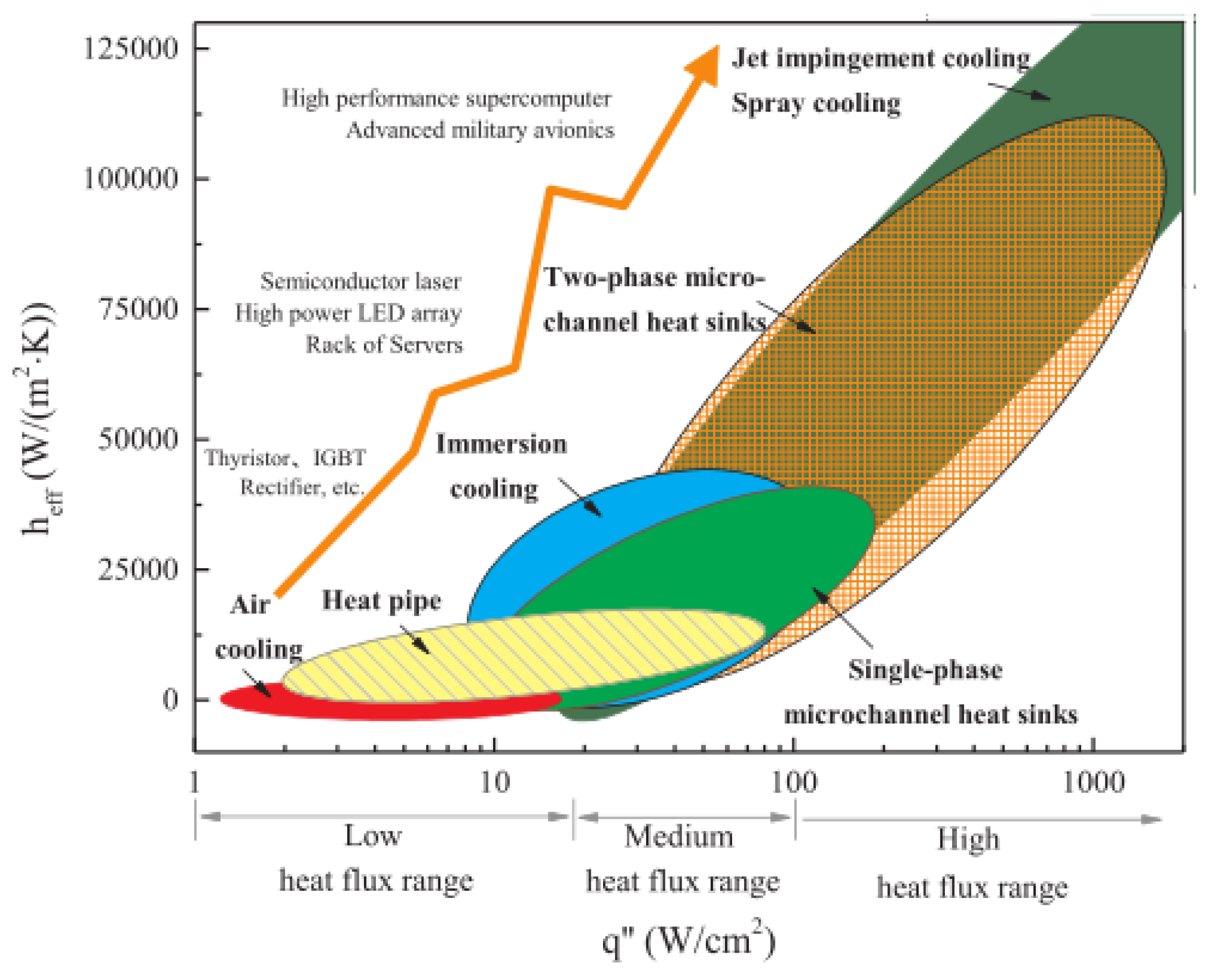
18] used a combination of experiments and simulations to investigate the heat dissipation capabilities of forced air cooling and immersion cooling. The research results show that the measured thermal resistance of the three-dimensional stacked mold structure from the joint to the environment is reduced from 26 °C/W under natural convection to 7.6 °C/W under forced air cooling and 0.6 °C/W under immersion cooling. Additionally, when 1 W of power is applied to each chip layer, the temperature distribution variation rates for forced air cooling and immersion cooling are 5.8% and 7.4%, respectively. Bao K et al. [
19] summarized the heat flux density range applicable to traditional air-cooling, heat pipe cooling, and liquid cooling technologies, as shown in
Figure 1. When the heat flux density is greater than 100 W/cm
2, air cooling and heat pipe cooling are no longer applicable. Immersion cooling shows great potential for cooling high-performance stacked mold structures [
20].
The immersive cooling system can be divided into single-phase and two-phase immersion cooling, depending on whether phase change occurs or not. Both methods involve immersing the heating equipment in a special cooling liquid to remove surface heat through direct contact between the cooling medium and the heating equipment. The single-phase immersion cooling system mainly increases the efficiency of the cooling system and reduces the energy consumption of the entire system by selecting a cooling medium with a high heat transfer coefficient. The two-phase immersed cooling system primarily utilizes the phase change of the coolant on the surface of electronic devices, absorbing heat and reducing thermal resistance in the convective heat transfer process [
21]. This effectively improves the cooling efficiency and reduces the energy consumption of accessories such as fans. The air handling unit is replaced by a pump, significantly reducing the power requirements compared to traditional air-cooling methods. Furthermore, the space required for immersion cooling technology is reduced to nearly one-third of that required for traditional air-cooling technology [
22]. This is mainly due to its higher power utilization efficiency and rack density compared to traditional cold plates and air-cooling techniques. Therefore, immersed phase change cooling has lower energy consumption and a Power Usage Effectiveness (PUE) value closer to 1 when compared to traditional methods of cooling. Against the background of carbon neutrality and carbon peak, the immersion phase change cooling method has become the preferred cooling method for data centers due to its high heat transfer efficiency and low energy consumption. Cheng C. et al. [
23] designed a single-phase immersion cooling structure combining a radiator and forced circulation and simulated the effects of different cooling agent flow rates on the cooling effect. The simulation results showed that the higher the flow rate of the refrigerant, the greater the heat dissipation and the lower the chip temperature. Kanbur B et al. [
24] evaluated and compared the thermodynamic and economic benefits of single-phase and two-phase immersion cooling systems, and the evaluation results showed that the performance trend coefficient of the latter was 72% to 79% higher than that of the former. Although its heat transfer efficiency is high, due to its complex boiling heat transfer mechanism, there is no complete set of cooling strategies. So far, many scholars have conducted a large number of simulation and experimental studies on the cooling effect [
25], cooling liquid selection, and boiling heat transfer mechanisms of the immersion phase change cooling technology. Kanbur B et al. [
26] also conducted a system-level thermal management of the immersion phase change cooling data center through experiments under six different real-time and dynamic operating loads ranging from 3.43 kW to 9.17 kW, studying its thermodynamic and thermal economic performance. The experiment showed that the COP and PUE values at the highest operating load were 6.67 and 1.15, respectively, and the best COP and PUE values at the lowest operating load were 2.5 and 1.4, respectively. Zhang et al. [
27] used Novec 649 as the cooling fluid and compared the coefficient of performance (COP) between traditional air-cooling methods and immersion-based phase change cooling methods in four cities. The COP of the immersion-based cooling system was 6.7–7.7 times higher than that of the traditional air-cooling system in the four representative cities. Therefore, the PUE value of the two-phase immersion cooling method can be reduced to about 1.4, which greatly improves the cooling efficiency and energy savings compared to air-cooled cooling methods. Many scholars have also applied immersed phase change cooling technology to the thermal management of batteries. Yang et al. [
28] found that lithium-ion batteries cooled by immersing them in SF33 as the coolant have significant advantages over natural convection in controlling battery temperature. Wang et al. [
29] also explored the immersed phase change cooling technology for lithium-ion batteries and found that the battery’s optimal operating time was extended by 150.3% compared to natural convection cooling. The above studies indicate that immersed phase change cooling technology has strong advantages in the thermal management of high-heat flux devices.
At the same time, the selection of the cooling liquid in the two-phase immersion cooling method is also crucial. Since the cooling liquid of the immersion phase change cooling system is in direct contact with the electronic chip, the qualified cooling medium should have the following basic characteristics: (1) meet insulation requirements in both gas and liquid states; (2) high heat of vaporization; (3) low boiling point; and (4) environmentally friendly and easy to handle. Li et al. [
9] investigated the thermal performance of three different cooling fluids (ethanol, FC-72, and R113). Experimental results showed that ethanol had better thermal performance. Under forced convection conditions, the total thermal resistance of ethanol was the lowest at 0.0703 °C/W for a 1000 W heat load. Under natural convection conditions, the total thermal resistance of ethanol was also the lowest, with a minimum value of 0.2 °C/W (for a 300 W heat load). The high insulation, high latent heat of vaporization, and low boiling point of the fluorinated liquid make it the preferred coolant in immersed phase change cooling technology.
As the integration level of electronic chips continues to increase, data center server rooms are also constantly expanding and upgrading. In addition to the research on the above cooling system strategies, reducing the size of the cabinet and server has also become one of the research hotspots. An et al. [
30] used ANSYS Fluent to conduct a three-dimensional numerical analysis of two-phase immersion cooling schemes in high-performance processor design, studying two different arrangements of heat sources, which were arranged vertically between two heat sources and separately arranged. The simulation results showed that when the two heat sources were arranged in series, the temperature of the upper heat source was significantly higher than that of the lower heat source, and Novec 7000 could support cooling of a 5 cm × 5 cm heat source in the vertical direction with a power of up to 225 W (a heat flux of 9 W/cm
2). However, if two such heat sources are thermally coupled, the power of the upper heat source must be less than 185 W. Based on this study, the vertical coupling of heat sources can be set to reduce the size of the entire cabinet and thus the footprint of the entire server room.
Although many scholars have conducted extensive research on the thermal management of chips and cabinets based on immersion cooling systems, exploring the effects of different factors on temperature distribution and cooling medium flow characteristics in cabinets, there is a lack of research on the boiling characteristics of cooling media under different pressures. Based on the previous research, this paper takes HFE-7100 as the cooling medium for the entire two-phase immersion experimental system and verifies the effects of different cooling water inlet temperatures and different cooling water flow rates on the system’s heat dissipation capacity through experiments. The study aimed to investigate the impact of various factors on boiling phase transition by analyzing the temperature distribution and bubble generation in the submerged phase change cell chip under different pressure conditions. The Fluent analysis software, which is based on the finite volume method, was utilized for the analysis. The impact of the above factors on heat dissipation is analyzed and summarized, providing reference for the cooling strategy and design of data center cabinets.
2. Establishment of a Simulation Model
Immersed cooling can be divided into single-phase immersed cooling and two-phase immersed cooling according to whether a phase change occurs. Single-phase immersed cooling mainly absorbs heat through the sensible heat of the cooling medium, and the cooling medium used is mainly mineral oil [
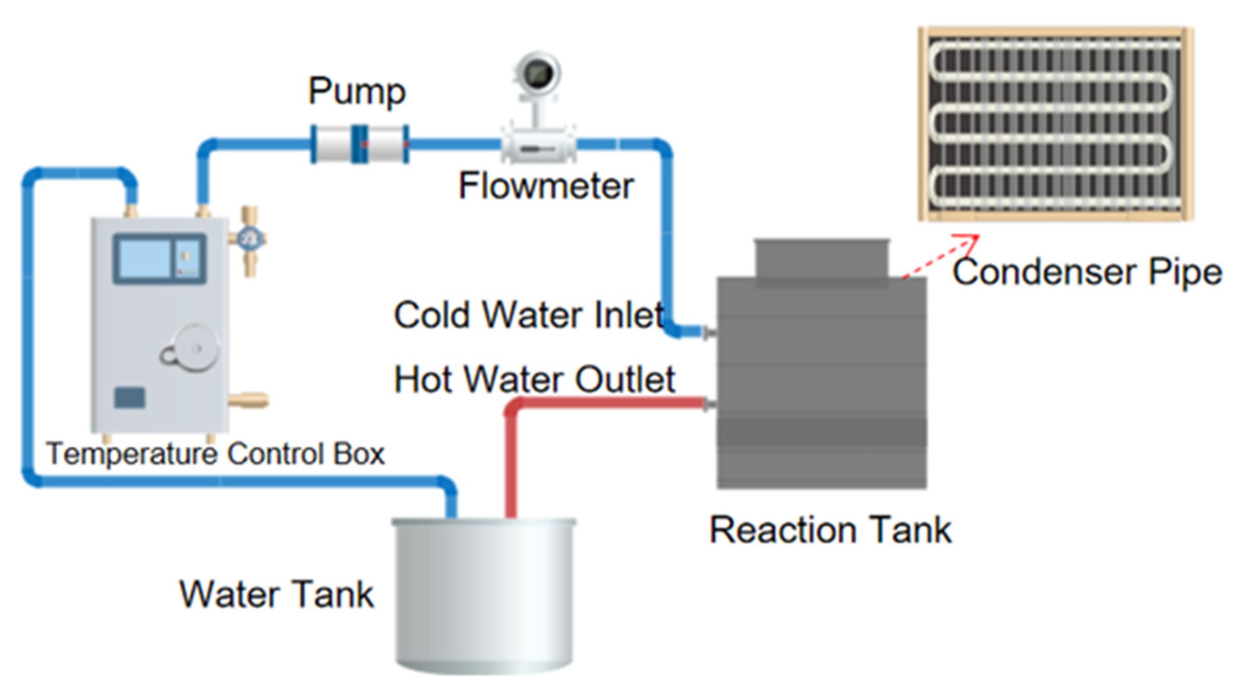
31], deionized water, and high-boiling-point fluorinated liquid. Two-phase immersed cooling mainly takes away heat through the latent heat of the cooling medium. The main working principle is to place the cooling medium and the electronic devices to be cooled in a closed phase change pool. After the cooling liquid absorbs heat from the electronic devices, it removes heat by boiling and evaporating. The vapor condenses at the top condensing plate and transfers heat to the cooling water. The cooling liquid returns to the evaporation end under the action of gravity and continues the next heat exchange cycle. The schematic diagram of the immersed phase change cooling system is shown in
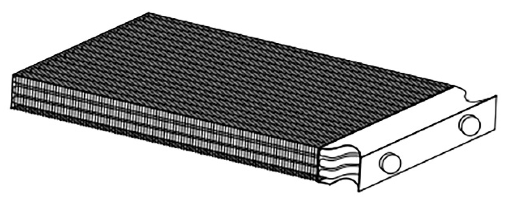
Figure 2. The system mainly consists of a boiling reaction pool, a temperature control system, a temperature acquisition system, and a condensation module. The core of the system is the boiling reaction pool, which can generate boiling phenomena at high temperatures, thus achieving fast heat transfer. The temperature control system can automatically control the temperature in the reaction pool to ensure the accuracy and stability of the experiment. The temperature acquisition system can monitor the temperature changes in the reaction pool in real-time. The condensing module mainly includes a condensing plate, an external refrigeration pump, and a circulation pipeline. The structure of the condensing plate is shown in
Figure 3, which is used to maintain the overall temperature of the system, ensuring the stability and safety of the experimental environment.
2.1. Selection of Cooling Liquid
Taking into account several properties such as comprehensive insulation, latent heat value, combustibility, viscosity, etc., the electronic fluorinated liquids mainly used in immersion-type phase-change liquid-cooled data centers currently include FC-40, FC-72, HFE-7100, HFE-7000, FC-77, and Novec 649 [
32]. The physical parameters of several electronic fluorinated liquids are shown in
Table 1. FC-40 and FC-77 have higher boiling points and require more heat to initiate boiling, so only single-phase heat exchange can occur when the chip’s safe temperature is below 85 °C, making it difficult to ensure the chip’s safe temperature of 85 °C. HFE-7000 has a lower boiling point than FC-40 and FC-77, requiring less heat to initiate boiling. The surface of the chip boils when the server is idle, increasing the power consumption of the external cooling pump for cooling water refrigeration. Therefore, this article does not consider FC-40, FC-77, or HFE-7000 as cooling media for the system.
The boiling of electronic fluorinated liquid on the surface of a component to produce bubbles requires a nucleation site and a certain degree of superheat. In the calculation process below, this article assumes that the radius of the nucleation site generated on the chip surface is 0.65 μm. Based on the equilibrium condition of internal and external forces on the bubble and the Clausius–Clapeyron equation, the degree of superheat required for different electronic fluorinated liquids to undergo nucleate boiling is shown in Formula (1):
where
is the temperature on the surface of the chip in the server, K;
is the saturation temperature of the electronic fluorine liquid, K;
is the surface tension of the electronic fluorine liquid, N/m;
is the latent heat of vaporization of the electronic fluorine liquid, kJ/kg;
is the radius of the vaporization nucleus, with a value of 0.65
;
is the density of the gaseous phase of the electronic fluorine liquid, kg/m
3; and
is the density of the liquid phase of the electronic fluorine liquid, kg/m
3.
As the heat flux density continues to increase, when it reaches the value corresponding to the transition from nucleate boiling to transition boiling, the number of vaporization nuclei on the heating surface will increase, and the size of bubbles will also become larger. Multiple bubbles may merge into a large one, covering part of the heating surface. Because the heat transfer coefficient of the gas film is low, this will cause the temperature of the heating surface to rise rapidly, which may eventually lead to the heating surface burning. The heat flux corresponding to this point is called the critical heat flux (CHF). When the heat flux density on the surface of the chip component exceeds the CHF of the electronic fluorine liquid, the component on the surface of the chip will quickly rise, which may cause damage to the component. The estimation of CHF uses the modified formula based on the Zuber equation by Lienhard et al. [
37], as shown in Formula (2):
In the equation, each parameter is the same as in Equation (1), where g is the acceleration due to gravity, m/s
2. By substituting the various parameters of the electron-fluoride liquid into Equations (1) and (2), the corresponding wall superheat and critical heat flux (CHF) at boiling are shown in
Table 2.
Based on the calculation results of wall superheat and critical heat flux, the required boiling temperatures of the three cooling mediums all meet the safe operating temperature of electronic components in the server. HFE-7100 has the highest critical heat flux. Combining Wu’s [
38] research on the phase-change performance of different fluorinated liquids in cooling systems, the research results show that when HFE-7100 is used as the cooling medium for the system, it carries the most heat with the cooling water. The latent heat of FC-72 and Novec 649 is lower than that of HFE-7100, and the amount of heat carried per unit mass is lower. Many scholars use HFE-7100 as the cooling liquid to study chip-level thermal management. Yang et al. [
39] used HFE-7100 as the cooling medium to explore the single-phase cooling of the chip in the microchannel through experiments. Therefore, HFE-7100 is selected as the cooling medium of the immersion phase change cooling system in this paper.
2.2. Physical Model
The main focus of this paper is on the thermal analysis of electronic components inside a server. Due to the difficulty of visualizing the microscopic process of boiling heat transfer, numerical simulation will be used to investigate the phenomenon. The data center cabinet is accurately modeled, and mesh independence verification is performed to obtain the most appropriate and computationally efficient number of mesh cells and nodes. The VOF method has the advantages of easy realization, low computational complexity, and high precision [
40]. The VOF multiphase flow model in the CFD software Fluent is used to simulate phase change and explore the effects of different factors on boiling heat transfer [
41].
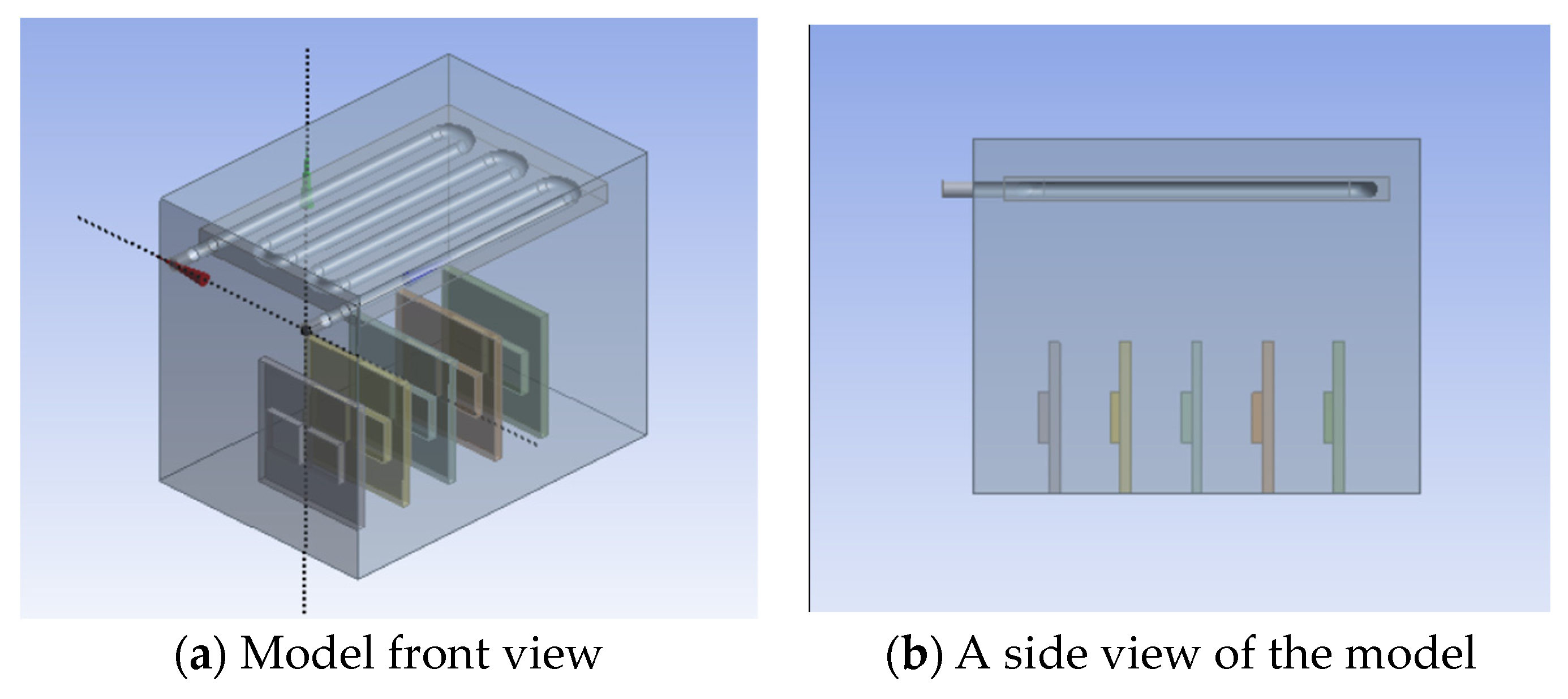
The internal structure of a server is very complex and composed of many components. Therefore, the server needs to be simplified before modeling. Considering that the chip is the main source of heat in the server, the modeling process in this paper only focuses on the heat source of the chip and ignores other components with relatively small heat generation. The required model for exploring the effect of cooling water inlet temperature and velocity on the heat dissipation performance in the condensation module of the immersion phase-change cooling system is shown in
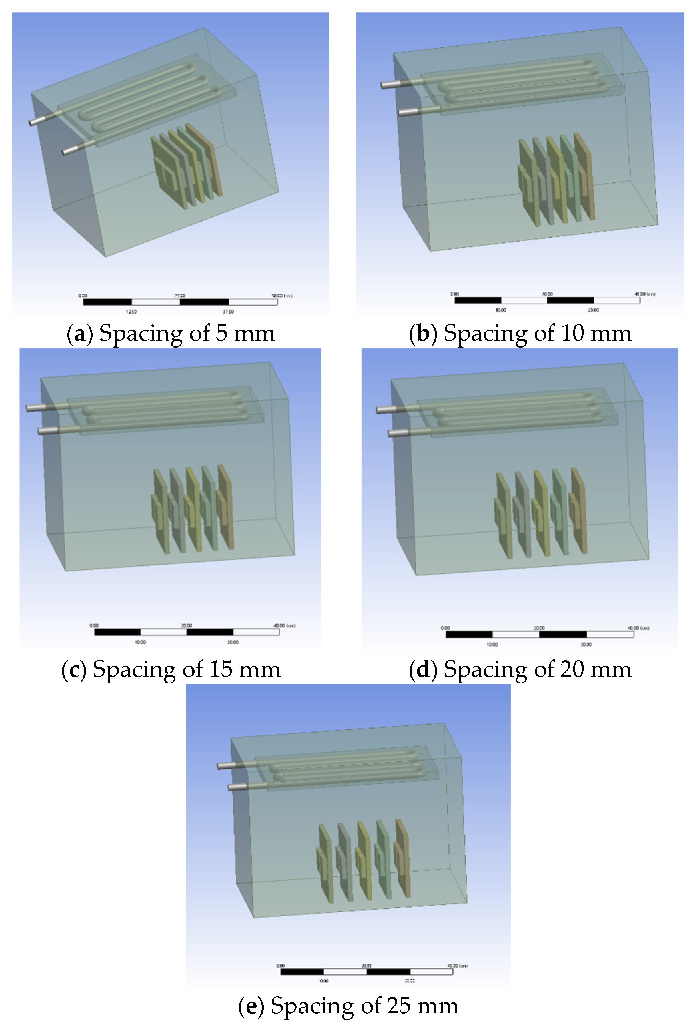
Figure 4, and the required model for exploring the effect of server spacing on the overall heat dissipation performance of the system is shown in
Figure 5.
The overall size of the model is 50 cm × 36 cm × 40 cm, which includes 10 chips, each with a size of 5 cm × 5 cm × 1.5 cm, which is the main source of heat in the server. In this model, the closed-phase-change pool is located above the condensation reflux of the system. The condensation reflux area is equipped with an aluminum condensation plate measuring 38 cm × 2 cm × 2.4 cm. Inside the condensation plate, there is a condensation tube with an inner diameter of 0.8 cm that connects the inlet and outlet ports on both sides. Cooling water continuously enters the condensation tube from the inlet port, exchanges heat with the system, and then flows out from the outlet port. This simplified model will help us better understand the internal structure of the server.
2.3. Numerical Model
In the heat exchange process, mass, momentum, and energy are exchanged between the gas and liquid phases. To simplify calculations, the model is assumed to be a three-dimensional steady-state, incompressible flow. The influence of thermal radiation and the dissipative heat caused by the viscous force of the fluid are neglected.
In the paper, the Volume of Fluid (VOF) multiphase flow model was selected to describe the boiling heat transfer process. The mass, momentum, and energy transfer models between the two phases were considered.
2.3.1. VOF Model
The VOF (Volume of Fluid) model is capable of tracking a group of shared momentum equations and the volume fraction of each phase within the entire computational domain, enabling the capture of phase interfaces in every computational cell. It has been widely used in numerical simulations of multiphase flows. In the VOF model, the sum of volume fractions for each phase within each control volume is equal to 1.
where
is the volume fraction of the liquid phase and
is the volume fraction of the gas phase.
By solving the continuity equation for each phase, the gas-liquid interface can be tracked. The volume fraction equations for the liquid phase and the gas phase are given by:
where
is the density of the liquid phase and
is the density of the gas phase; u is the velocity of the liquid phase; and
is the mass source term of the liquid phase, where
is the mass source term of the gas phase. The volume fraction equations cannot be solved for the primary phase. The volume fraction equation for the primary phase is obtained by solving Equation (3).
The momentum equation and the energy equation are given, respectively, by:
where p is the pressure;
is the gravity volume force; and
is the viscosity. “
” includes external volume forces and source terms.
where E is energy per unit mass,
is the effective thermal conductivity, and
is other volumetric heat sources.
where E
f is the latent heat energy of the liquid phase and E
g is the latent heat energy of the gas phase.
2.3.2. Turbulence Models
Fluent software commonly uses turbulence models such as the standard k-epsilon model, the RNG k-epsilon model, the realizable k-epsilon model, the Spalart–Allmaras model, LES, etc. The turbulence model is used to describe the turbulent behavior of the flow. Through analysis, it is observed that almost all coolant flows are in a turbulent state. Therefore, we have chosen the standard k-epsilon turbulence model for this model. This model assumes that the flow is fully turbulent and that the effect of molecular viscosity can be ignored. The solution is obtained by solving the turbulent kinetic energy k equation and the turbulent dissipation rate ε equation, followed by the calculation of the turbulent viscosity. This standard k-ε turbulence model is only suitable for simulating fully turbulent flow processes. The formulas for turbulent kinetic energy and dissipation rate are shown in Equations (9) and (10), respectively:
In Equation (9), where is the dynamic viscosity of the fluid; is the generation of turbulence kinetic energy due to the mean velocity gradients; is the generation of turbulence kinetic energy due to buoyancy; is the contribution of the fluctuating dilatation in compressible turbulence to the overall dissipation rate; is the user-defined source term; and is the turbulent viscosity. In Equation (10), is the user-defined source term; where and are the turbulent Prandtl numbers for the k and ε equations, with = 1.0 and = 1.3; , are constants.
2.3.3. Evaporation-Condensation Model
The original Lee model in Fluent can meet the requirements of the model. The Lee model is a semi-empirical model used to describe the evaporation and condensation processes in multi-component mixtures. It is widely applied to handle the evaporation and condensation phenomena in complex fluid systems. Through continuous debugging and comparison between simulated results and the boiling phenomenon of HFE-7100 in actual experiments, the evaporative coefficient was ultimately set to 200, and the condensation coefficient was set to 500 in the Lee model.
2.4. Preprocessing and Solving the Algorithm of the Model
The preprocessing of the entire physical model mainly includes grid partitioning, selecting appropriate models, setting boundary conditions, and choosing algorithms. The external walls of the model are set as adiabatic walls with no-slip conditions. The cooling water inlet is set as a velocity inlet, and the outlet is set as a free flow outlet. The chip is the heat source of the entire model and is set to constant power, with its surface being a fluid-solid coupling surface. The condensation plate is made of aluminum, and the wall is set as a coupling surface. A transient solver is selected, and the gravity option is turned on along the y-axis with a gravity of −9.81 m/s2. The pressure uses the PRESTO! interpolation method, the volume fraction uses the geometric reconstruction interpolation method, and energy and momentum use the second-order upwind interpolation format to improve computational accuracy. The time step is set to 0.001. Monitoring parameters are set as chip surface temperature, chip body temperature, pressure change, and heat flux density.
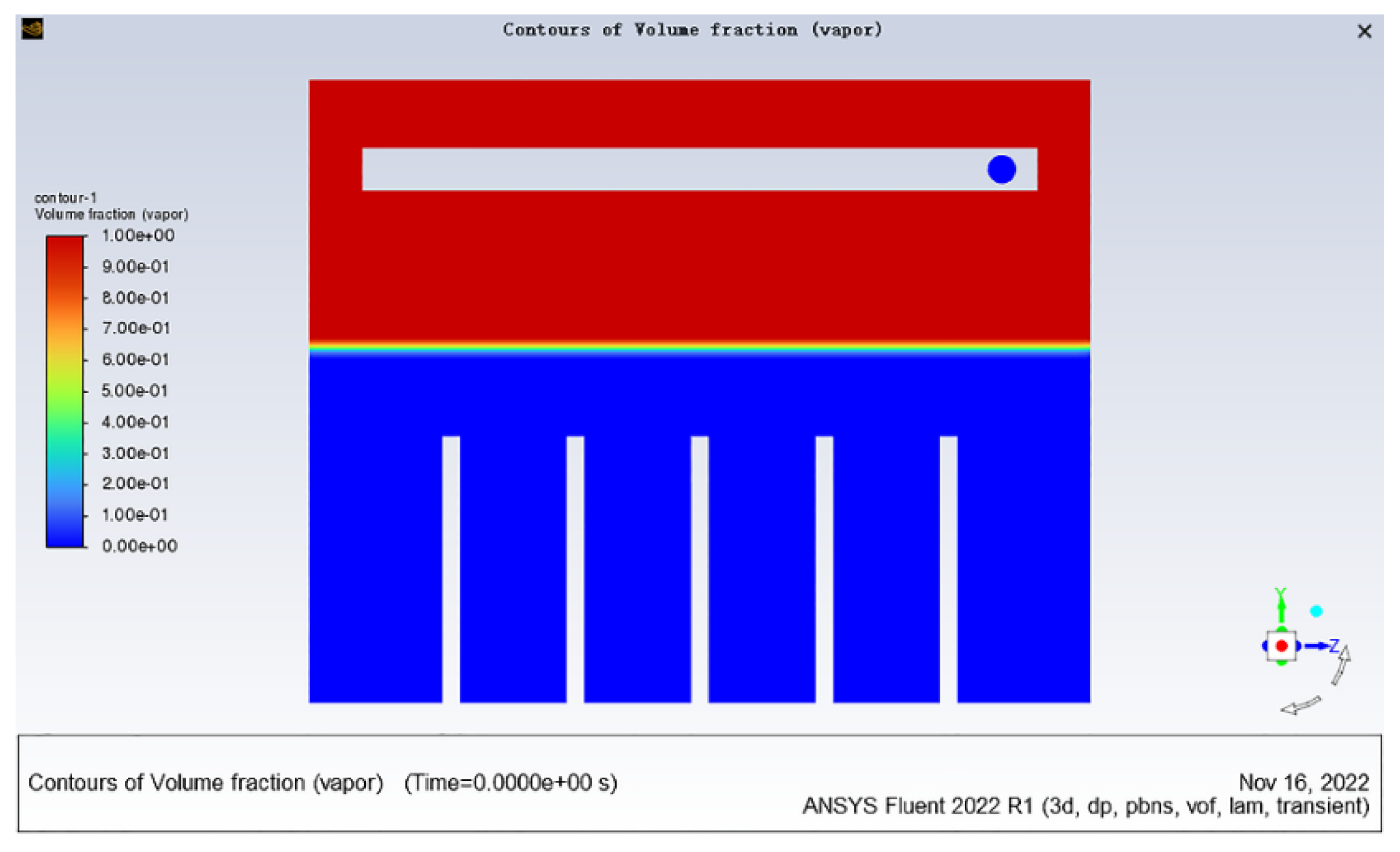
The immersion height of the cooling liquid in the immersion phase change pool is 20 cm. Taking the model in
Figure 4 as an example, the phase distribution cloud map of the initial time in the Fluent preprocessing is shown in
Figure 6. The volume fraction of the gas phase in the cooling liquid region is 0.
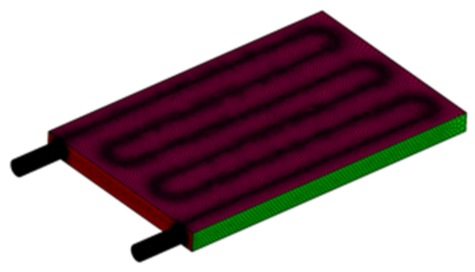
2.5. Grid Independence Verification
In this paper, a structured grid with shared nodes is globally applied to the three-dimensional model, and the grid is locally refined at the condenser plate using a poly-hexcore grid. The poly-hexcore grid connects the hexahedral grid and the polyhedral grid with shared nodes (without interface faces), which does not require any additional manual grid settings compared to traditional hexahedral grid division, resulting in higher grid quality, improved calculation accuracy, and efficiency. Some examples of locally refined grids are shown in
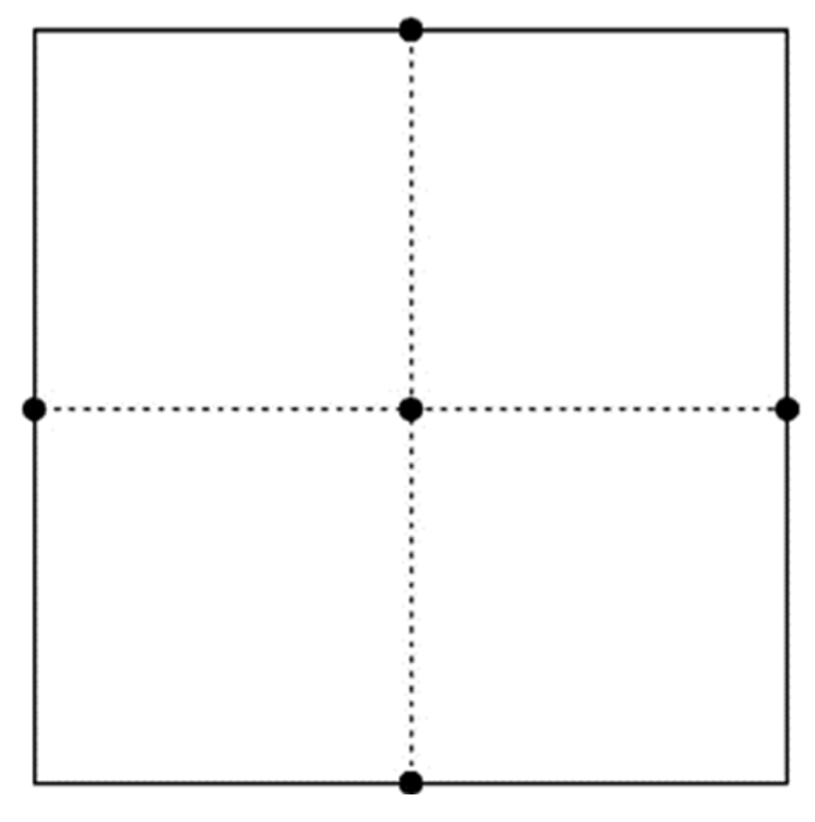
Figure 7. The main board in the physical model is numbered from S1 to S5 from left to right, and the central points of each chip are taken as monitoring points, as shown in
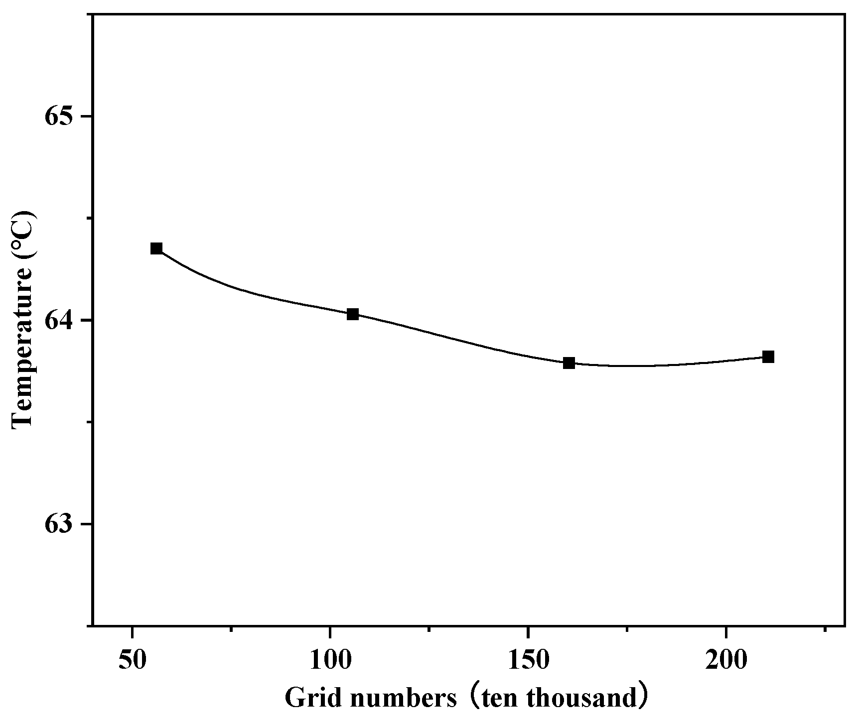
Figure 8. To verify the impact of the number and nodes of the grid on the calculation results, four different grid division cases were used for grid independence verification. The cooling water inlet temperature was set to 24 °C, and the cooling water flow rate was 0.5 m/s. As shown in
Figure 9, when the grid was divided into 2,106,986 cells, the temperature variation rate was only 0.04%, which did not show a significant difference from the case of 1,603,698 cells. To ensure calculation accuracy and save computing resources, a grid of 1,603,698 cells was selected for the calculation. The default convergence criterion in Fluent is that all variables’ residual values except for the energy residual value are below 10
−3, and the calculation process converges. After the calculation process converges, the temperature averages of the two chips on the No. 3 motherboard under different grid number models are compared.
2.6. Model Validation
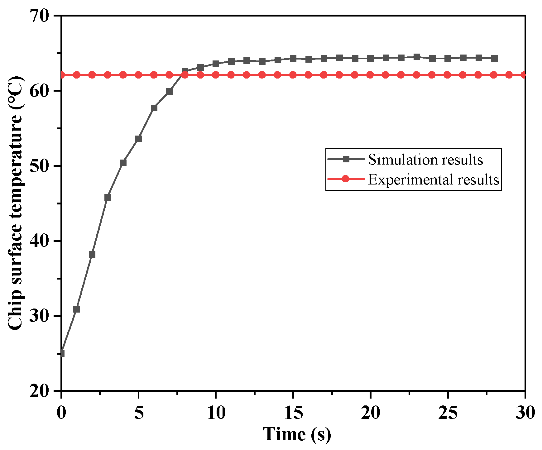
In order to validate the applicability and accuracy of the model, the experimental results were compared and analyzed against the simulation results. We compared the experimental data with the simulation data under operating conditions of a cooling water inlet temperature of 20 °C and a flow velocity of 1 m/s. The comparative results indicated that the maximum difference in the surface temperature of the heat source, after reaching a stable state, did not exceed 2.5 °C, as shown in
Figure 10. Considering the complexity of flow boiling and the inevitable heat losses in the experimental setup, this level of uncertainty is acceptable.
2.7. Evaluation Index
Temperature is an important factor that affects the operation of servers. High temperatures can increase the kinetic energy of “electron migration,” causing atoms to detach, ultimately leading to short circuits or open circuits, which can affect the lifespan of the server. Moreover, high temperatures can reduce the reliability of servers. High temperatures can increase latency and prevent servers from reaching their rated frequency, leading to latency faults. Research shows that for every 10 °C increase in chip temperature, the probability of chip failure increases by an order of magnitude [
42]. Conversely, for every 1 °C decrease in chip temperature, the failure rate of the chip decreases by 4%. Therefore, temperature is an important condition for ensuring the lifespan and reliability of servers. In this article, the maximum temperature is used as the evaluation metric for thermal safety, and the temperature fluctuation is used as the evaluation metric for thermal stability, to investigate the cooling effect of different factors on the immersion phase-change cooling system:
When the maximum temperature of the chip reaches 85 °C, the chip will fail. Therefore, the primary principle of the cabinet cooling system is to maintain the chip temperature below 85 °C. The highest temperature in the entire boiling pool occurs at the heat source chip. Therefore, the maximum temperature is the maximum value of all the highest chip temperatures;
- (2)
Temperature Difference
The formula for calculating the temperature difference is as follows:
For a chip, where is the temperature difference, °C; is the maximum temperature of the chip, °C; and is the minimum temperature of the chip, °C. For the entire cabinet level, where is the highest temperature of all measurement points on the chips in the cabinet, °C; and is the lowest temperature of all measurement points on the chips in the cabinet, °C;
- (3)
Temperature uniformity coefficient: In modification to the temperature uniformity coefficient formula proposed by Sun et al. [
1], the
coefficient is used to evaluate the thermal stability of the entire system, with its calculation formula shown in Equation (12):
where
is the number of chips within the system;
is the average temperature of a certain chip, °C; and
is the average temperature of the entire system, °C.
3. Results and Discussion
As shown in
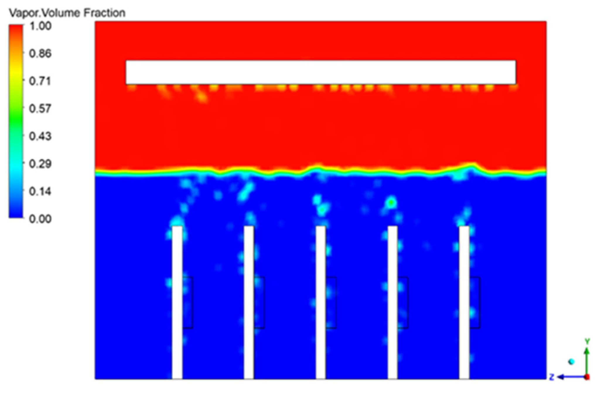
Figure 11, during the calculation process, the generation of bubbles is observed. As the surface temperature of the chip continues to increase, when the temperature approaches the boiling point of HFE-7100, bubbles nucleate on the surface of the chip, grow, detach from the wall, and merge, indicating a good bubble generation state.
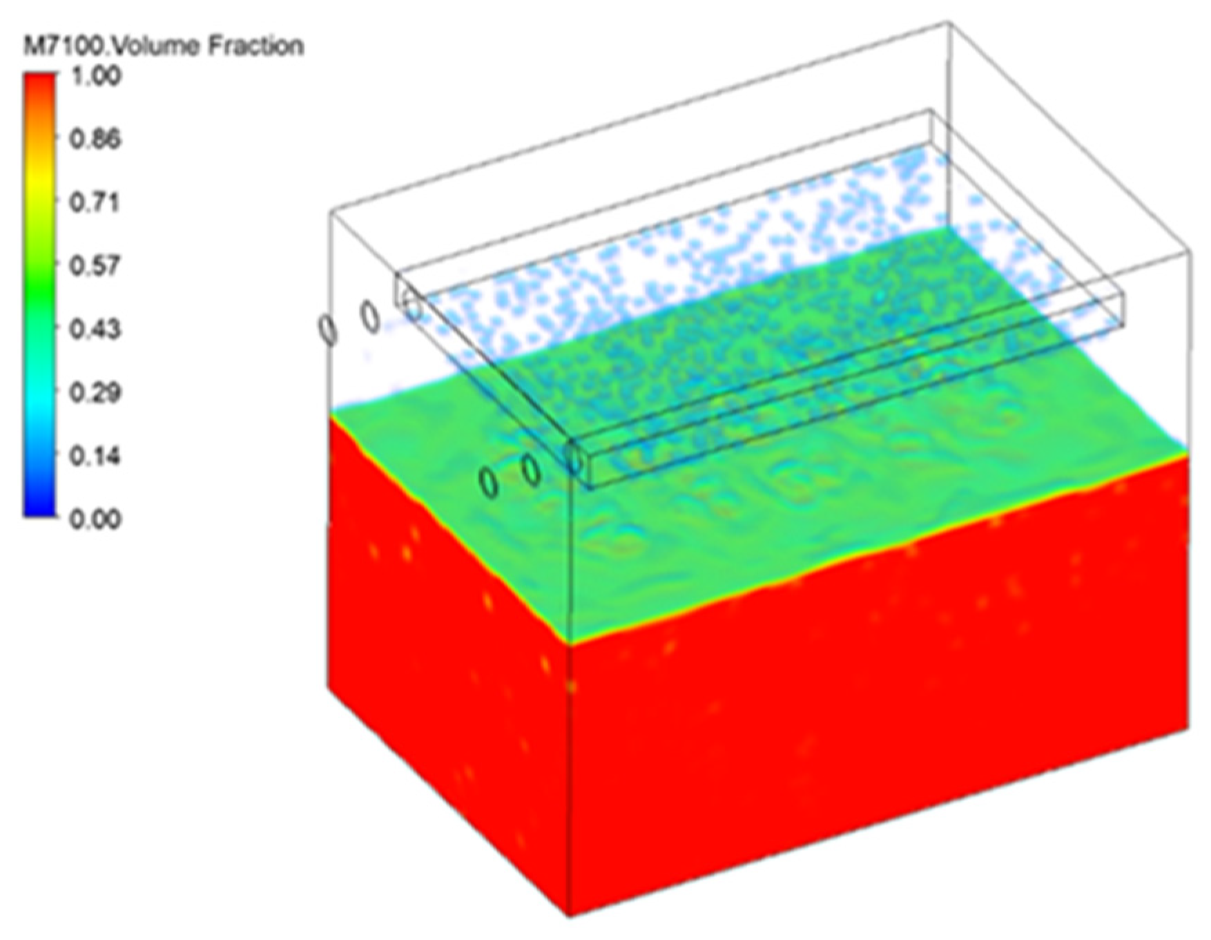
Figure 12 shows the volume fraction of HFE-7100 coolant monitored during the calculation process. As the bubbles rise and reach the upper condensation plate, gaseous HFE-7100 condenses due to the entry of low-temperature, constant-temperature cooling water in the upper condensation plate, and liquid droplets continuously form and fall back into the boiling pool at the bottom under the action of gravity.
Figure 13 shows the condensation droplets observed at the condensation plate, indicating a good condensation effect.
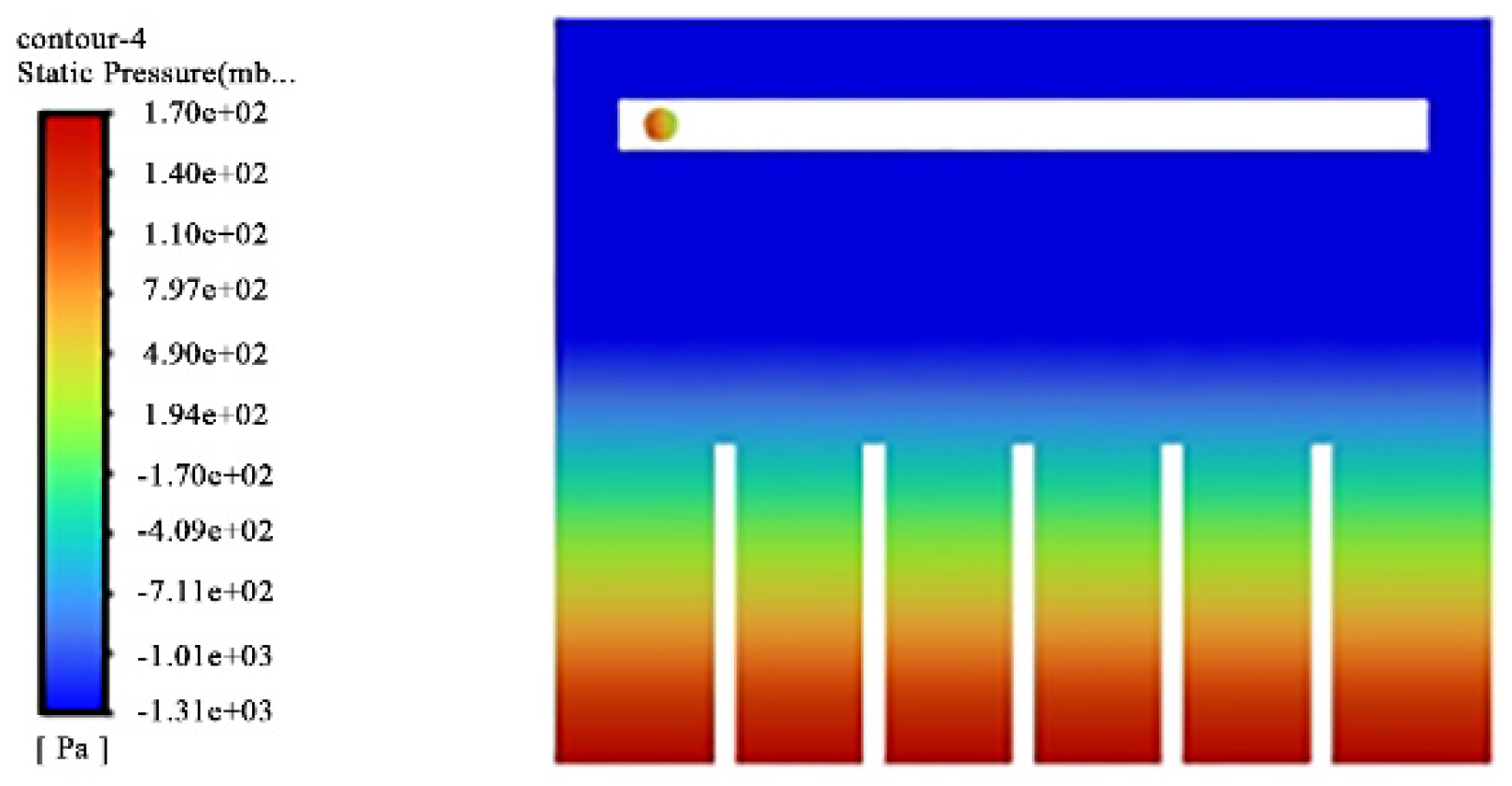
Figure 14 shows the internal pressure changes monitored during the bubble generation process. As bubbles continuously nucleate and generate in the HFE-7100 area at the bottom, the pressure in the coolant area changes.
3.1. The Influence of Different Inlet Water Temperatures on the Cooling Effect
A continuous inflow of cooling water is used in the entire immersion-type phase-change heat dissipation system to condense the vapor generated in the boiling pool and absorb the heat generated in the entire boiling pool. Under the condition of a constant inlet water velocity, numerical simulation and analysis were conducted for inlet water temperatures of 15 °C, 20 °C, 24 °C, and 30 °C. As shown in
Figure 8, the middle point of the chip is the monitoring point, and the highest temperature is the maximum value of the two highest temperatures on each circuit board.
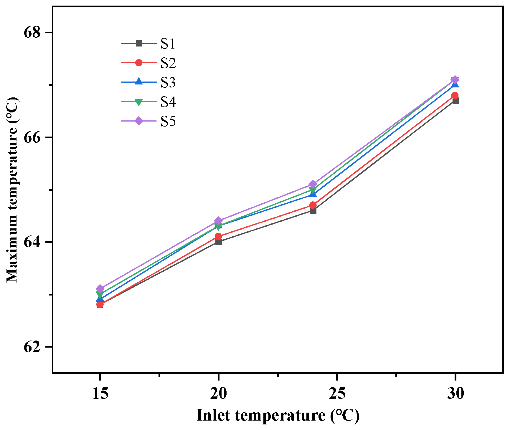
Figure 15 shows the curve of the highest temperature on each motherboard with the change in inlet water temperature over time. As the inlet water temperature increases by 5 °C, the highest temperature of the five motherboards shows an overall upward trend, but they are all lower than the safe operating temperature of 85 °C for the chip. From left to right, the maximum temperature of chips on each motherboard of S1–S5 increases gradually, but the difference is small. The main reason for this phenomenon is that as the temperature of the motherboard rises, the coolant will boil and generate bubbles. The heating surface is located on the left side of the motherboard, and most of the bubbles are discharged from the left side of each motherboard. During the rising process of the bubbles, due to the gap between the main boards, the bubbles may not be discharged smoothly, causing the maximum temperature of S1–S5 to gradually increase. Taking the temperature change of S5 as an example, when the inlet water temperature decreases from 30 °C to 24 °C, the highest temperature decreases by 1.54%, and when the inlet water temperature decreases from 24 °C to 20 °C, the highest temperature decreases by 1%, with a smaller degree of change.
As shown in
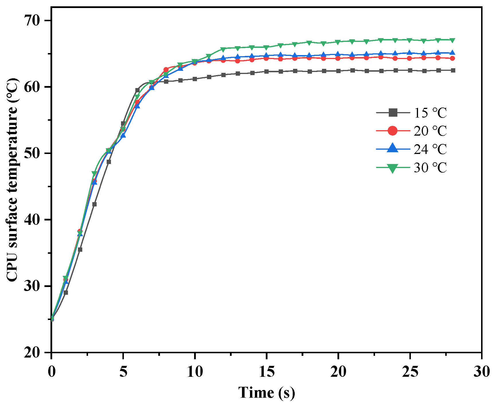
Figure 16, when HFE-7100 is used as the cooling medium and the cooling water flow rate is constant, the temperature change curve of the chip surface under different cooling water inlet temperatures is obtained, and the average value of the temperature change on all chip surfaces is taken. From the figure, it can be seen that the trend of chip surface temperature change requires a longer time to reach stability as the cooling water inlet temperature increases. This is mainly because when the cooling water inlet temperature is low, the temperature difference with the entire boiling phase change pool is large, and the rate of heat transfer is determined by the heat conduction equation, in which the heat conduction rate is proportional to the temperature difference. Therefore, as the temperature difference increases, the heat conduction rate also increases, in accordance with Fourier’s law. The chip surface temperature after stabilization increases with the increase in the cooling water inlet temperature. It can be seen from the figure that when the cooling water inlet temperature is 20 °C and 24 °C, the difference in stabilized temperature is less than 1 °C, and selecting 20 °C will result in additional power consumption of the external cooling pump.
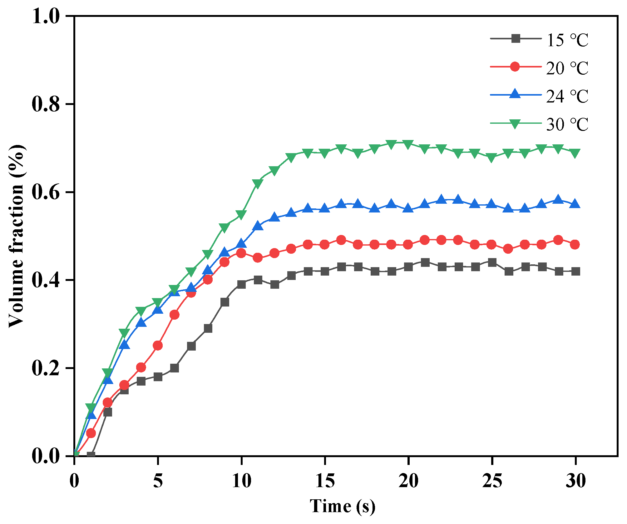
Figure 17 shows the curve of the surface vapor-phase HFE-7100 volume fraction on the chip monitored over time with different cooling water inlet temperatures when HFE-7100 is used as the cooling medium. Overall, the surface vapor-phase HFE-7100 volume fraction exhibits an increasing trend. In the first stage, the HFE-7100 volume fraction increases slowly without any occurrence of subcooled boiling. In the second stage, when the temperature of the entire fluid region has not yet reached saturation temperature, bubbles are generated due to the high local temperature of the chip, resulting in subcooled boiling and a noticeable increase in the surface volume fraction. In the third stage, when the temperature rises to the saturation temperature of HFE-7100 and stabilizes, the surface volume fraction also stabilizes and no longer exhibits a significant increasing trend. The subcooled boiling phenomenon occurs first when the cooling water inlet temperature is higher, and therefore the surface volume fraction shows an increasing trend earlier. The surface vapor-phase HFE-7100 volume fraction increases with the increase in cooling water inlet temperature.
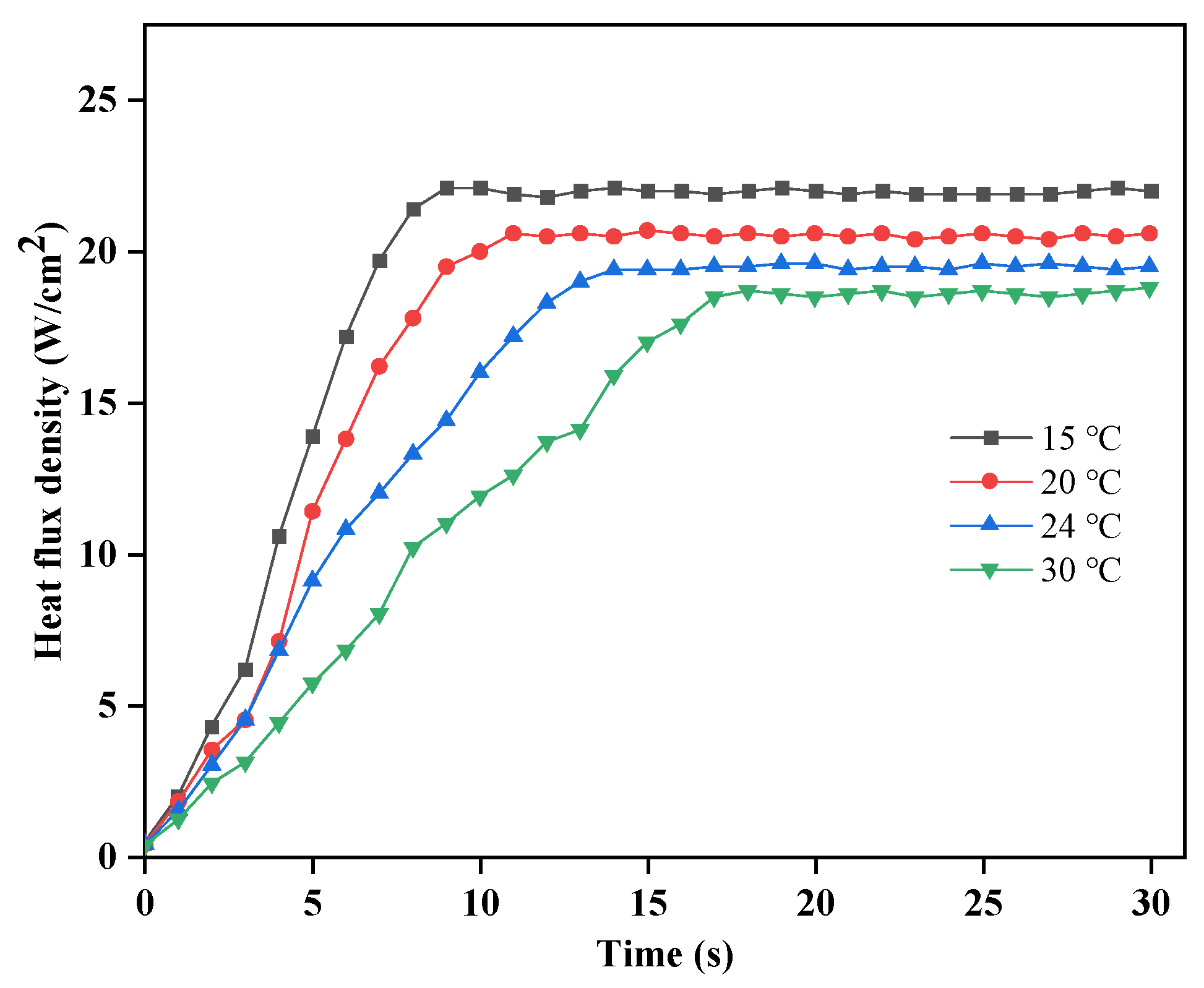
The surface heat flux density of the chip as a function of the cooling water inlet temperature is shown in
Figure 18. The overall trend of the heat flux density can be seen to have three stages: a slow rise, a rapid rise, and a stable phase. The variation in cooling water inlet temperature has a minor effect on the initial stage, but in the second stage, as the cooling water temperature increases, the heat flux density decreases. When the cooling water inlet temperature is high, the temperature of the HFE-7100 coolant drops more slowly, reducing the amount of heat absorbed by the coolant and the surface heat flux density. At the same time, the time it takes for the surface heat flux density on the chip to reach a certain temperature decreases as the cooling water temperature decreases.
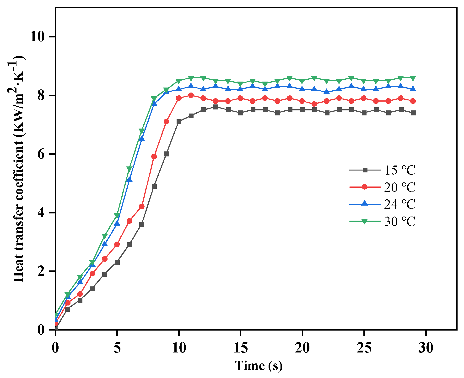
The surface heat transfer coefficient of the chip as a function of the inlet water temperature is shown in
Figure 19. From the graph, it can be seen that the overall trend of the heat transfer coefficient can be divided into three stages: slow growth, rapid growth, and stability. When the temperature starts to increase, the heat transfer between the chip and the coolant is a single-phase convective heat transfer, and the surface heat transfer coefficient shows a slow growth. As the temperature gradually increases, the heat transfer changes from single-phase convective heat transfer to nucleate boiling and then to saturated boiling, and the heat transfer coefficient shows a rapid increase and tends to stabilize with temperature.
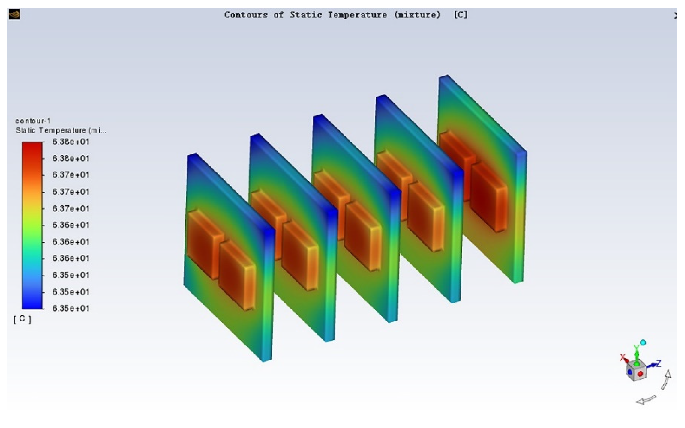
The temperature cloud map of the chip surface when the cooling water flow rate is 1 m/s and the inlet temperature is 24 °C is shown in
Figure 20. It can be seen from the figure that the highest temperature in the entire cabinet appears at the center of the heating element, with a maximum temperature of 63.8 °C, and the lowest temperature of the entire heating element is 63.5 °C, with a temperature difference of only 0.3 °C, and the temperature fluctuation is small.
3.2. The Effect of Different Cooling Water Inlet Flow Rates on Cooling Performance
Numerical simulations were conducted under working conditions with cooling water inlet temperatures of 24 °C and inlet flow rates of 0.6 m/s, 0.8 m/s, 1 m/s, and 1.2 m/s, respectively.
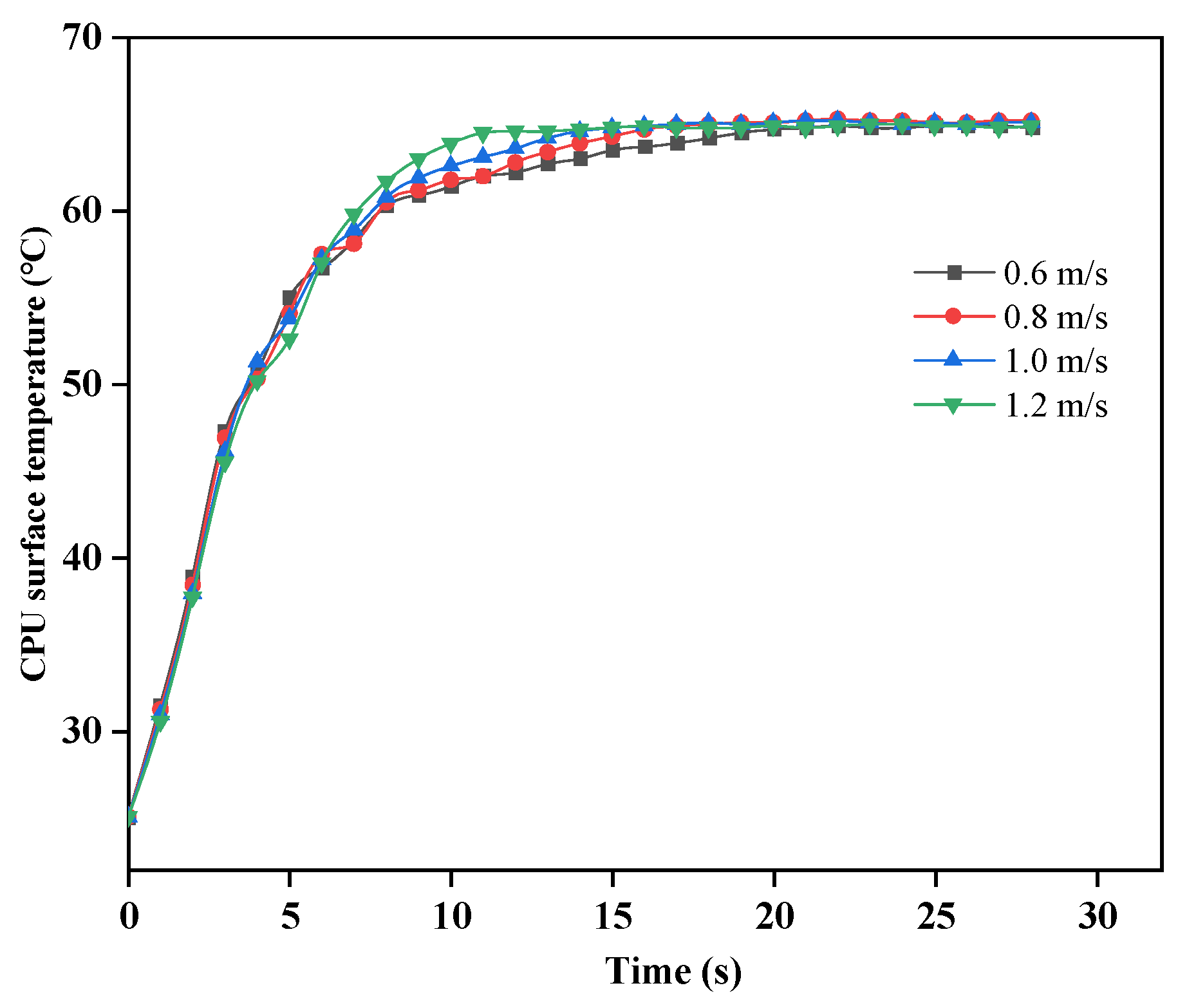
Figure 21 shows the curve of the average chip surface temperature over time after stabilization under different cooling water flow rates when the cooling water inlet temperature is 24 °C. It can be seen from the figure that the temperature change of the chip surface after stabilization is less affected by the cooling water flow rate, and the temperature difference after stabilization is very small at different inlet flow rates. However, the higher the cooling water inlet flow rate, the shorter the time required for the chip to reach a stable temperature, and the heat in the system is discharged in a timely manner when the cooling water inlet flow rate is high.
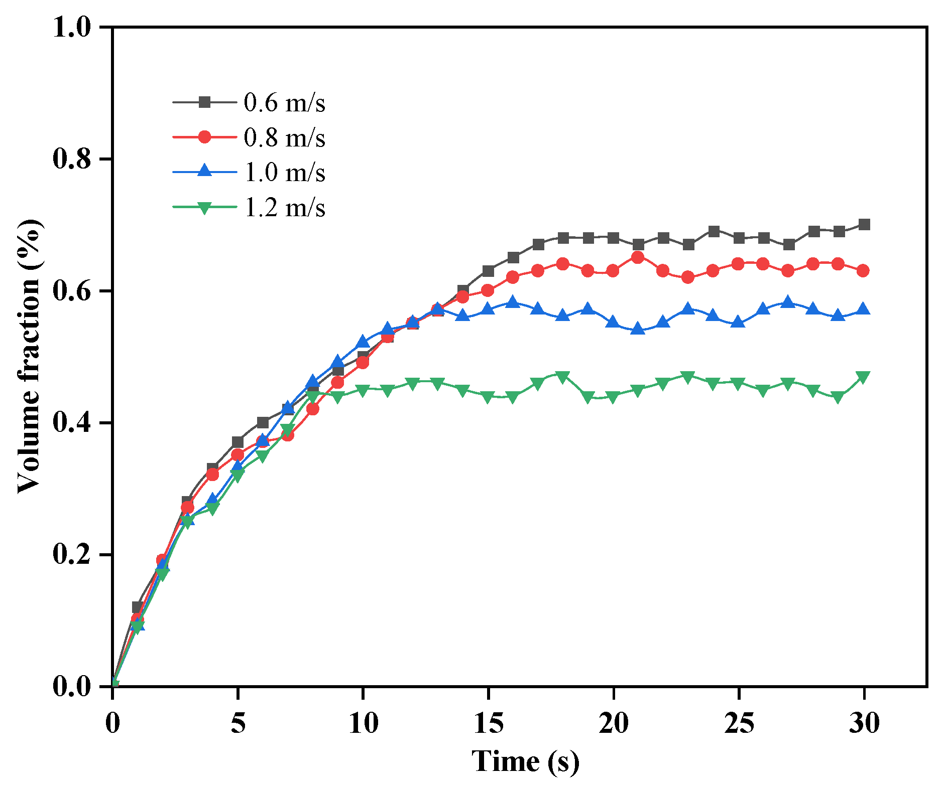
As shown in
Figure 22, the curve depicts the variation of the gas volume fraction over time within the entire immersion phase change cooling system under different cooling water flow rates. From the graph, it can be seen that the gas volume fraction of HFE-7100 increases over time under different cooling water inlet flow rates, and the rate of increase is relatively fast. This is because bubbles are produced when the temperature of the heat source increases to the saturation temperature of the cooling medium. However, eventually, the gas volume fraction tends to stabilize. In the first half of the curve, the gas volume fraction is less affected by the cooling water flow rate, and there is little difference in the gas volume fraction under different flow rates. As the temperature continues to rise, the faster the cooling water inlet flow rate, the smaller the gas volume fraction of HFE-7100. The main reason is that in the first half of the curve, there are fewer gases produced due to the high local temperature, and even with a lower cooling water flow rate, gas condensation can still be achieved. When the temperature reaches the saturation boiling point, the faster the cooling water flow rate, the less heat is absorbed by the cooling water per unit volume, and the smaller the temperature rise of the cooling water in the heat exchange process. Therefore, the time required for the gas phase HFE-7100 to condense into a liquid phase at the condensation plate is shorter, and the gas phase HFE-7100 stays in the entire system for a shorter period of time, resulting in a smaller volume fraction.
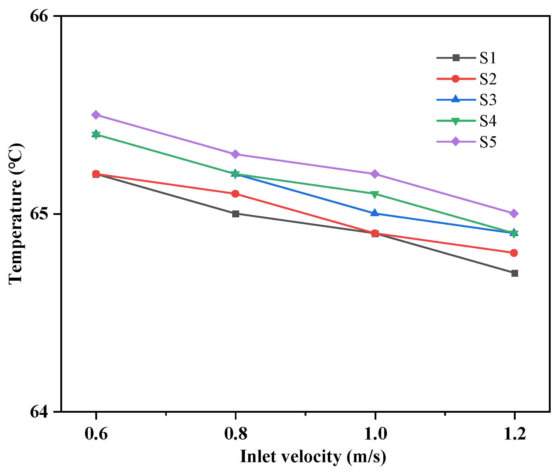
As shown in
Figure 23, the highest temperatures observed between each S1–S5 plate under different cooling water flow rates are presented. Based on the changes shown in the figure, it can be observed that the cooling water flow rate has a relatively small effect on temperature variation. The maximum temperature difference between each chip under different flow rates is only 0.3 °C.
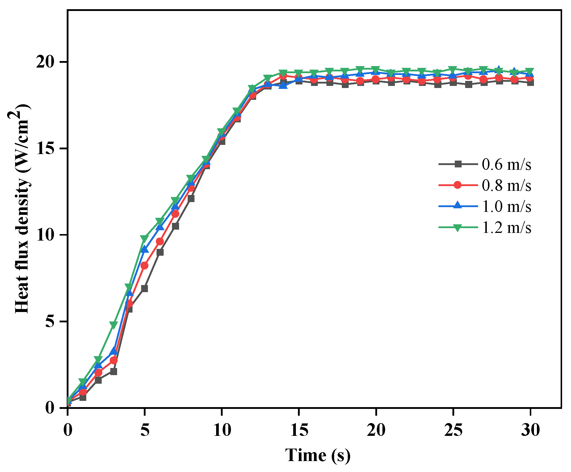
Figure 24 shows the variation of the surface heat flux density of the chip with the cooling water inlet flow rate. It can be seen from the graph that the surface heat flux density under different cooling water inlet flow rates differs very little. The overall trend of the heat flux density changes rapidly at first and then stabilizes. When the temperature has not reached the boiling point of the cooling medium, the heat transfer in the entire phase change pool relies on single-phase convection, resulting in a lower heat transfer rate and a slow increase in surface heat flux density. When the heat transfer between the heat source surface and the cooling medium changes from single-phase convection to phase change heat transfer, the heat transfer rate increases, and the surface heat flux density increases rapidly and tends to be stable.
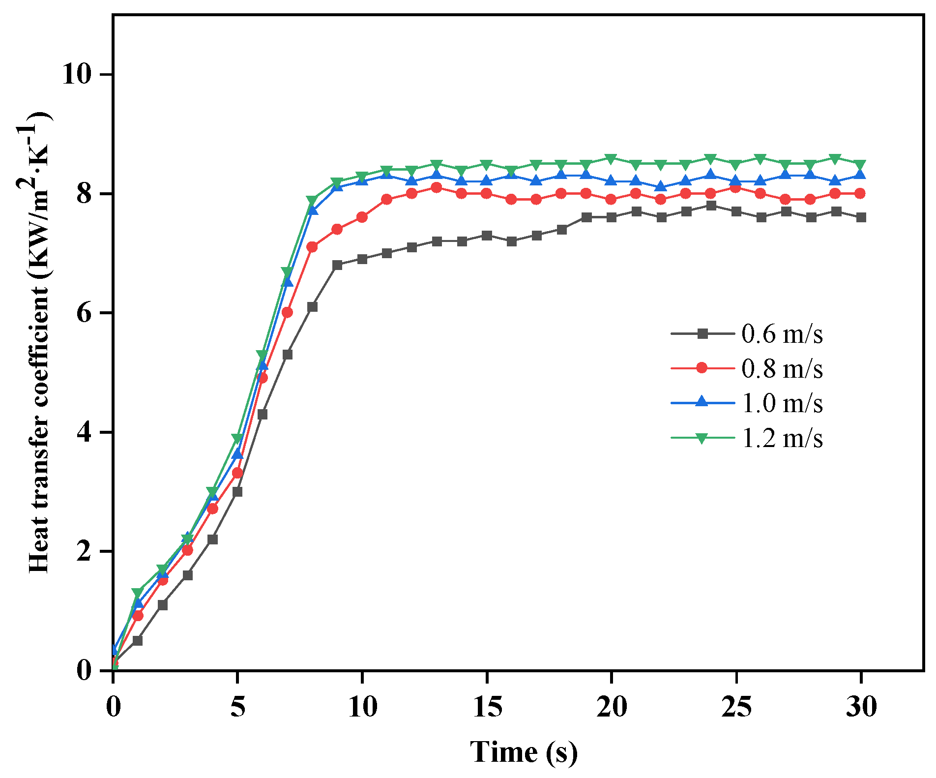
Figure 25 shows the variation of the surface heat transfer coefficient of the chip with the cooling water inlet flow rate. It can be seen from the graph that the overall heat transfer coefficient shows an increasing trend, and the influence of flow rate on the heat transfer coefficient is relatively small.
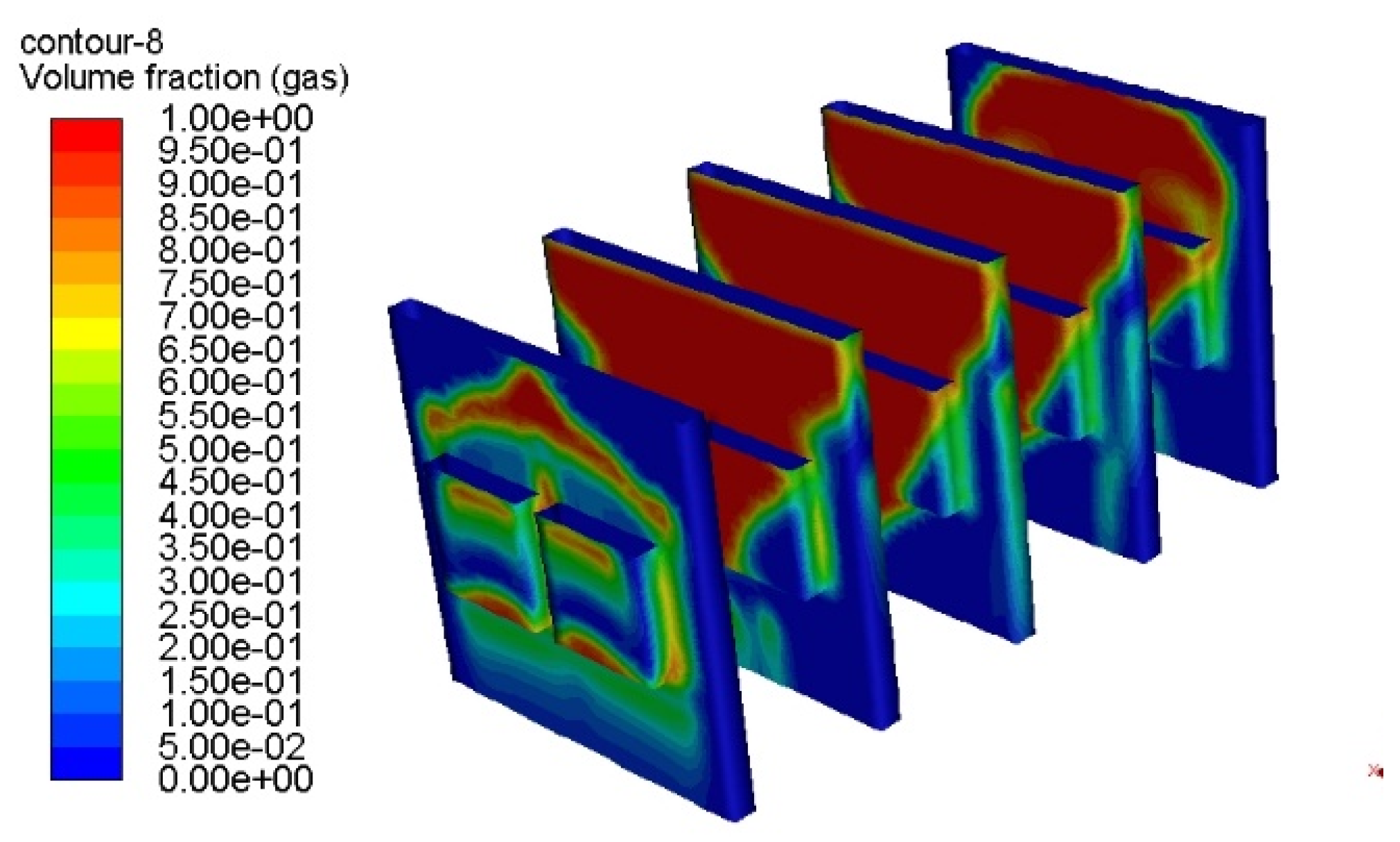
Figure 26 shows a cloud map of the phase volume distribution of HFE-7100 in the heat dissipation system under steady-state conditions. It can be observed from the figure that the gas volume fraction is highest near the heat source, and the gas phase volume fraction on the upper surface of all heat sources is higher than that on the lower surface. This phenomenon is mainly due to the bubbles generated in the lower part carrying heat to the upper part during detachment and ascent, resulting in a higher local temperature in the upper part than in the lower part. At this time, more vaporization nuclei are generated in the upper part, leading to more bubble formation, thus making the gas volume fraction higher in the upper part than in the lower part. In addition, it can be seen from the figure that the volume fraction on the left side of the motherboard is smaller than that on the right side. This trend is consistent with the temperature distribution cloud map of the chip surface when the cooling water flow rate is 1 m/s and the inlet temperature is 24 °C. The main reason is that the heat source is located on the left side of the motherboard. As the temperature rises, the cooling liquid temperature near the heating side of the motherboard is slightly higher than that on the back side. Therefore, from left to right, both the temperature and gas phase volume fraction increase.
3.3. The Influence of Different Arrangement Intervals on the Heat Dissipation Performance of the System
In the design of servers, the arrangement structure of the servers is one of the important factors that affects heat dissipation performance. The impact of different arrangement structures on heat dissipation performance may be closely related to factors such as the environment in which the servers are located and the server’s workload. The server arrangement structure not only directly affects the space utilization and energy utilization efficiency of data centers but also affects aspects such as the heat dissipation performance, data transmission efficiency, and maintenance management difficulty of data centers. It also provides guidance for reducing the package size of data centers. In order to study the impact of different arrangement structures on the overall system heat dissipation performance, this article simulates the heat dissipation performance of the entire system under different server arrangement intervals with the same cooling water inlet temperature and flow rate.
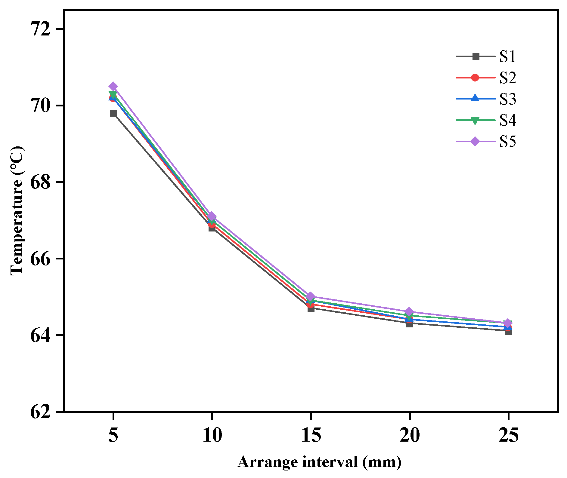
As shown in
Figure 27, the highest temperature between chips on each circuit board S1–S5 is compared at different intervals when the servers are vertically arranged. When the interval between the main boards increases from 5 mm to 10 mm, the highest temperature value decreases by 5.06%. However, when the interval increases from 15 mm to 20 mm, the highest temperature only decreases by 0.61%. This is because when the interval is 15 mm, the middle interval is sufficient for the synthesis, rise, and detachment of bubbles, and there is no accumulation of bubbles.
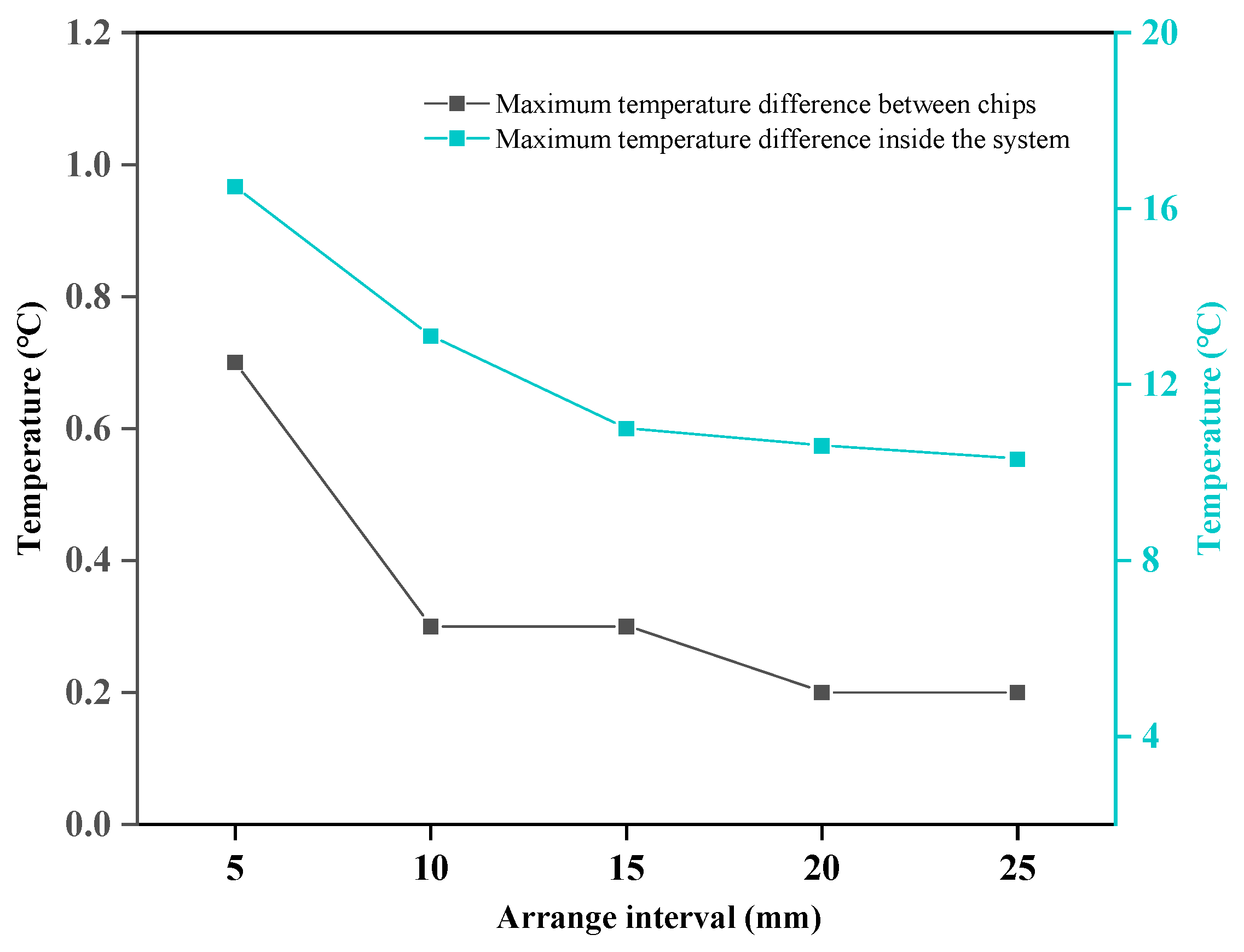
As shown in
Figure 28, the maximum temperature difference between internal chips and the entire system under each arrangement interval is shown. From the figure, it can be seen that as the interval increases, the maximum temperature difference between chips and the entire system decreases. When the interval between servers is 5 mm, the maximum temperature difference in the entire system reaches 16.5 °C, and it gradually decreases as the interval between different servers increases. When the interval is 15 mm, the temperature difference is 11 °C, which is 20.6% lower than that of 10 mm. When the interval continues to increase, the decrease in temperature difference is small, and when the interval is 20 mm, it is only 3.6% lower than that of 15 mm.
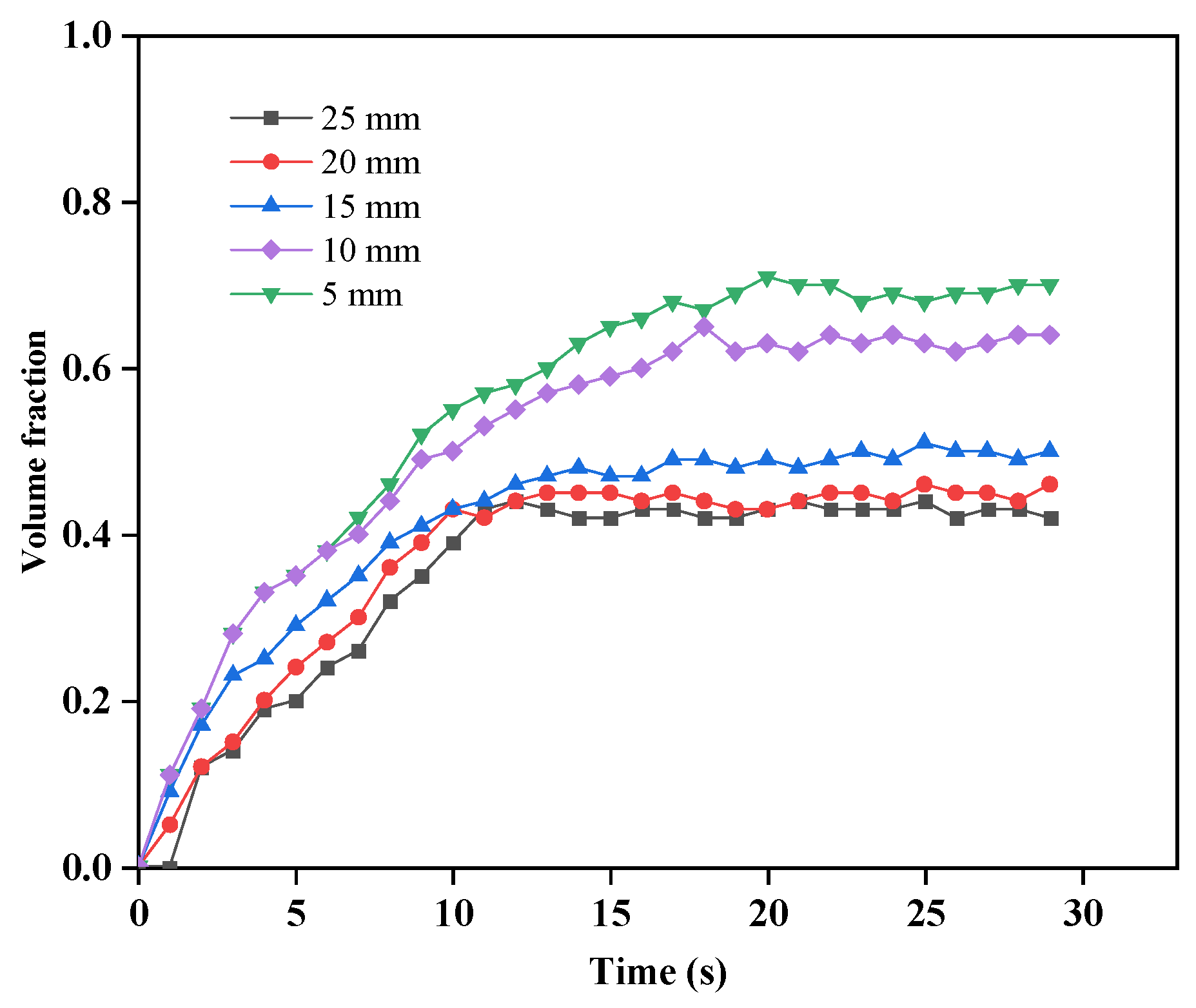
Monitor the changes in the volume fraction on the surface of the chip on the S3 motherboard in the middle of the monitoring system. As shown in
Figure 29, the curve of the HFE-7100 gas phase volume fraction on the S3 surface at different intervals over time is presented. The peak of the surface gas phase volume fraction decreases as the interval between the motherboards increases. When the distance between the boards is greater than 15 mm, the rate of decrease gradually slows down. There are mainly two reasons for this trend: firstly, the too small distance between the two motherboards leads to poor exhaust of the bubbles, which accumulate on the surface of the heat source; secondly, the smaller the interval, the higher the temperature on the surface of the heat source, which promotes the production of bubbles and increases the surface gas phase volume fraction. When the interval between the motherboards increases from 5 mm to 15 mm, the maximum surface volume fraction decreases from 71% to 51%, a decrease of 28.1%. When the interval between the motherboards increases from 15 mm to 20 mm, the volume fraction decreases from 51% to 46%, a decrease of 9.8%. When the interval changes between 15 mm and 25 mm, the decrease is 4%. This trend is consistent with the changes in the highest temperature on each circuit board at different intervals.
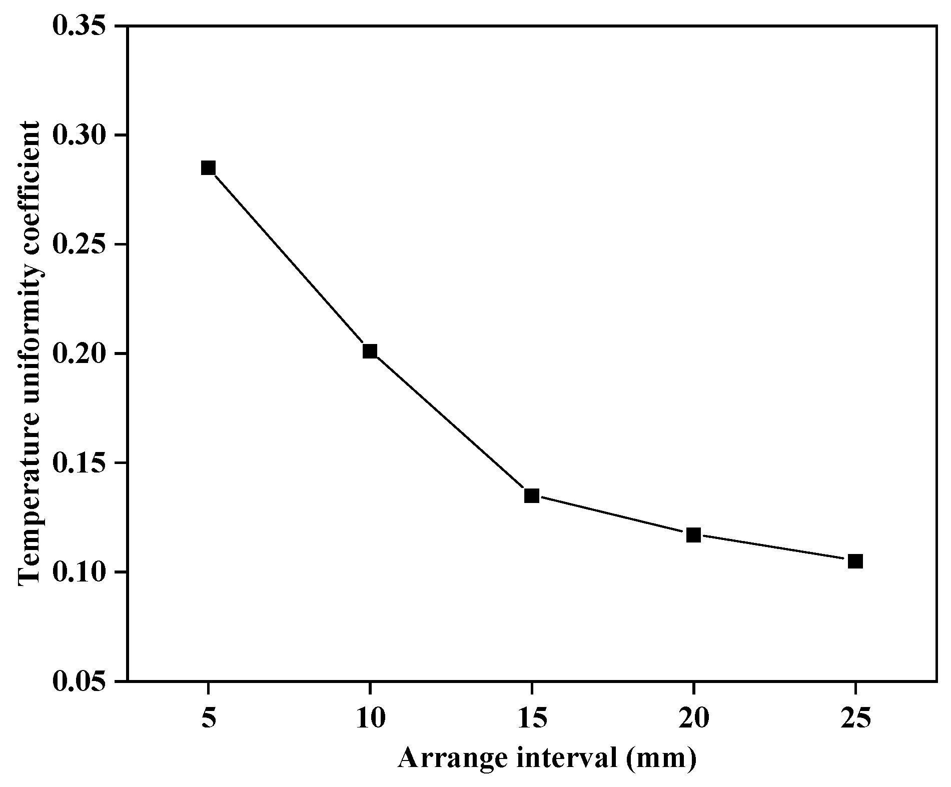
As shown in
Figure 30, the temperature uniformity coefficient of the entire system under different arrangement intervals can be seen from the graph. When the arrangement interval between the servers is 5 mm, the temperature uniformity coefficient is 0.285. When the interval between the servers increases from 5 mm to 15 mm, the temperature uniformity coefficient decreases by 52.6%. When the arrangement interval changes from 15 mm to 25 mm, the change in the temperature coefficient decreases by only 22%, and the trend becomes stable.
When the gap between chips increases from 5 mm to 15 mm, the temperature difference between the chips and the maximum temperature difference of the entire system, as well as the temperature uniformity coefficient, show a significant downward trend. When the gap is greater than 15 mm, the change tends to be stable. The main reason for this phenomenon is that when the gap is small, bubbles generated by temperature rise are merged and piled up between two servers, affecting heat transfer efficiency. Therefore, when the gap is greater than 15 mm, the volume fraction of the gas phase decreases.
Analyzing both thermal safety and thermal stability aspects, when the gap between the servers increases from 5 mm to 15 mm, the highest temperature in the system decreases by 5.06%, the temperature difference decreases from 16.5 °C to 11 °C, and the temperature uniformity coefficient decreases by 52.6%. When the gap increases from 15 mm to 25 mm, the highest temperature only decreases by 1.07%, the temperature difference decreases from 11 °C to 10.3 °C, and the temperature uniformity coefficient only decreases by 22%. Therefore, the optimal gap between the different servers is 15 mm, which ensures the heat dissipation effect of the entire system and effectively reduces the size of the entire system, allowing for more servers to be accommodated in the same area.


