Article

Evaluation of Efficiency for Miniscale Thermoelectric Converter under the Influence of Electrical and Thermal Resistance of Contacts

1
Institute of Thermoelectricity of the National Academy of Sciences and Ministry of Education and Science of Ukraine, 58029 Chernivtsi, Ukraine
2
Institute of Applied-Physics and Computer Sciences, Yuriy Fedkovych Chernivtsi National University, 58012 Chernivtsi, Ukraine
*
Author to whom correspondence should be addressed.
Energies 2023, 16(10), 4082; https://doi.org/10.3390/en16104082
Submission received: 24 March 2023 / Revised: 10 May 2023 / Accepted: 11 May 2023 / Published: 13 May 2023
(This article belongs to the Special Issue Theory and Applications of Thermoelectric Materials and Devices)

Abstract

:
Mass-produced thermoelectric modules are mainly fabricated with Bi2Te3-based materials. Due to the limited world reserves and the high price of tellurium, it must be saved. The miniaturization of thermoelectric converters is one of the modern trends to diminish the use of tellurium, reduce the cost of modules and expand the range of their applications. The main disadvantage of miniature thermoelectric converters operating in cooling or generating modes is their low energy efficiency, caused by the effect of electrical and thermal resistances of contacts, interconnectors and insulating plates. We propose an improved method for evaluating the maximum efficiency that takes into consideration the impact of these unwanted resistances. This method can also be used to design the modules with the optimal structure for cooling and energy generation, and not only to study their performance. The effect of undesirable electrical and thermal resistances on the maximum efficiency of cooling and generating converters made of Bi2Te3-based materials is analyzed. It is shown that the efficiency of miniature modules can be significantly improved if these resistances are reduced to their rational values. The decrease in electrical contact resistance is the predominant factor. The rational values to which it is advisable to decrease the electrical contact resistance have been determined. In the development of miniscale module technology, it is necessary to focus on such rational contact resistance values.

1. Introduction

The practical application of thermoelectricity is currently constrained by the relatively high cost of thermoelectric energy convertors. Figure 1a shows a diagram [1,2] of the growth in the market size of thermoelectric (TE) modules produced worldwide for the needs of thermoelectric power generation and cooling. The data are provided for the last 6 years with a prospect up to 2026. The market compound annual growth rate (CAGR) is about 9% [1,2]. Using this diagram and assuming that the average price of a standard TE module is near USD 15, we can easily estimate the annual production of modules in the world. The results of such a rough estimation are shown in Figure 1b. It can be seen that, at present, the production reaches about 54 million pieces per year. At the same time, the market potential is estimated at 6.2 billion pieces per year [3]. Consequently, the market for thermoelectric products, which are mainly cooling systems and converters of the waste heat into electricity, is provided for by less than 1% now. Therefore, the market needs are quite significant.
It is generally known that commercial TE modules are mainly fabricated with Bi2Te3-based materials. The main obstacle to increasing production is limited reserves, and hence the high price of tellurium. According to the estimates of the Energy Research Center (Great Britain), the world reserves of tellurium amount to 50 thousand tons only. The annual production of tellurium and its price in recent years are shown in Table 1 [4].
Therefore, today the average annual production of tellurium is more than 600 tons. Of this, 30% is spent on the needs of the thermoelectric industry [4], i.e., more than 180 tons per year. For a standard TE module, at least 5 g of tellurium is used. Consequently, the current level of tellurium production ensures today the manufacturing of approximately 36 million tellurium-containing modules per year, and the reserves of tellurium will suffice for 80 years. However, increasing the production of modules to at least 300 million pieces (which will correspond to 5% of the market demand only) will require 1500 tons of tellurium per year, and its annual production should be increased to at least 2000 tons. Then, the reserves of tellurium will last for 25 years only.
Therefore, for the development of the mass production of TE modules, it is necessary to reduce the use of tellurium drastically. There are several ways to do this. First of all, this is a search for new tellurium-free thermoelectric materials. Materials with high thermoelectric figures of merit and high mechanical properties are required.
No such materials have yet been proposed for thermoelectric coolers (TECs). Since the 1950s, cooling modules have been produced of Bi2Te3-based materials, whose dimensionless figure of merit remains at the level of 1–1.2 [5]. The search for new tellurium-free materials with increased figures of merit does not give tangible positive results.
For thermoelectric generators (TEGs), a number of compounds are being investigated. Skutterudites and clathrates [6,7] are considered promising materials. Their optimization is predominantly focused on reducing their lattice thermal conductivity. The most attractive for practical applications are CoSb3-based skutterudites [8] whose crystal lattices are supplemented to reduce their thermal conductivity by rare-earth, alkaline-earth, alkali metals and other ions. The highest figures of merit, ZT = 1.7 [9] and ZT = 1.9 [10] at T = 850 K, were achieved for skutterudites Ba0.08La0.05Yb0.04Co4Sb12 and Sr0.09 Ba0.11Yb0.05Co4Sb12.3, respectively. For clathrates, a high value of ZT = 1.35 [11] at T = 900 K was obtained for Ba8Ga16Ge30 single-crystalline samples synthesized using the Czochralski method.
Intermetallic compounds Mg2X (X = Si, Ge, Sn) are promising mid-temperature materials consisting of nontoxic and cheap elements. For solid solutions based on these compounds, such as Mg2Si1‒xGex [12], Mg2Si1‒xSnx [13] and Mg2Sn1‒xGex [14], ZT values in the range of 1.2–1.4 at near 800 K have been obtained for doped samples used as an n-type thermoelement in generator modules. For the p-type thermoelement, manganese silicides Mn4Si7 and Mn11Si19 with a figure of merit ZT in the range of 0.7–0.8 at 750 K are used [15,16]. Compounds such as Zn4Sb3 [17] and In4Se3 [18] are also promising for use in generator modules.
A lot of other compounds are being studied [8] for the middle range of operating temperatures from 500 K to 900 K and the high-temperature range from 900 K to 1300 K. For the low-temperature range from 300 K to 500 K, Bi2Te3-based materials remain the most effective for thermoelectric generators. However, it should be noted that for new materials it is necessary to adapt and change the technology of mass production of TE modules.
There is another effective way to save world resources, in particular tellurium, and reduce the cost of TE modules. This is a reduction in the consumption of thermoelectric materials by miniaturization of thermoelements and the TE module as a whole. Miniaturization of thermoelectric converters (modules) is a modern trend in the improvement and expansion of their practical use [19].
A particularly important task is the miniaturization of modules for TECs, in the mass production of which materials other than Bi2Te3-based compounds have not yet been used. Miniaturized cooling modules have a lot of important applications. Miniscale thermoelectric devices are used for cooling, controlling thermal conditions and stabilizing the temperature of electronic elements and systems. The main purpose of using a TEC is to remove heat and keep the electronic equipment at a normal operating temperature [20]. An additional task is to reduce the leakage current from electronic devices and the thermal noise from electrical components in order to improve the accuracy of devices [21]. An important application of TE modules is the spot cooling of electronic computer chips and their components [22,23,24]. Miniature TECs are used to control the temperature of the light-emitting diodes (LEDs) [25,26,27] and laser diodes [28,29] and to provide the required operating temperature of IR sensors [30,31,32,33].
Miniature TEGs are used in applications where a heat source is available and, in some cases, they can even replace batteries, for example, to power wireless sensors and autonomous circuitry placed in a harsh or remote environment [34,35]. These can be sensors for monitoring the operating condition of industrial processes or those in pipelines. TE converters are used in nuclear-based small-scale power sources for biomedical applications and implantable devices, such as pacemakers [36]. An example of such a Bi2Te3-based converter made of 215 μm thick wafers is described in [37]. Miniscale TEGs are promising energy sources for wearable electronics and the “Internet of Things” devices [38,39,40]. Different wearable products with TEGs that use body heat have been developed, for example, a pulse-oximeter [41], a body-powered electroencephalogram system [42] and a wireless electrocardiography system inserted into a shirt [43,44]. Flexible TE modules with miniature thermoelements integrated into a fabric or silicon matrix [45] are more suitable for power generation from the human body [46,47,48]. Since miniscale TEGs usually operate at near room temperature conditions, Bi2Te3-based materials are commonly used for such generators.
Thermoelectric converters are mechanically stable and highly reliable with a life cycle of up to 20 years. The main disadvantage here is their low energy efficiency. This study focuses on increasing the efficiency of miniscale TE modules for cooling and power generation. It should be noted that we identify the module with a length of thermoelements in the range from 500 μm to 200 μm as a miniature one. For the production of such modules, it is not necessary to change the existing technology. The conventional bulk technology with the manufacturing of thermoelements by thinning bulk materials is used [19,49].

2. Impact of Electrical and Thermal Contacts on Miniaturization of Thermoelectric Converters

It is well known that the efficiency of TE modules is mainly determined by the figure of merit Z = α 2 σ / κ , where α is the Seebeck coefficient, σ is the electrical conductivity and κ is the thermal conductivity of thermoelectric materials. However, it also depends on the electrical resistance of contacts at the boundaries between the semiconductor material of the legs and the metal connecting layers. A contact resistance is one of the main reasons for the fact that the thermoelectric properties of materials are not fully realized. The Joule heat releasing on the contacts reduces the efficiency of thermoelectric converters and leads to its dependence on the thermoelement length [50].
Figure 2 shows the dependences of efficiency (Figure 2a) and coefficient of performance (COP) (Figure 2b) on thermoelement length L for generating and cooling converters, respectively. The length L is indicated in Figure 3 below. These data have been calculated at a contact resistivity value of rc = 5 × 10⁻⁶ Ω cm2 [51], which is considered typical for mass-produced modules made of Bi2Te3-based materials.
To calculate the maximum efficiency and COP, the classical formulae [52] have been used, which are given as
η 0 = T h T c T h ( M 1 ) ( M + T c / T h ) , ε 0 = M T c T h Δ T ( M + 1 ) ,
where, M = 1 + Z T E ( T h + T c ) / 2 , Z T E = α 2 / ( ( ρ + 2 r c / L ) κ ) is the figure of merit of the thermoelement that depends on the value of contact resistivity rc. Th and Tc are the hot side and cold side temperatures, respectively, and ΔT = ThTc, ρ = 1 / σ is the electrical resistivity of the thermoelectric material.
The influence of contact resistance on the efficiency and COP becomes more significant under the condition of thermoelement miniaturization when the thickness of the thermoelectric material–metal interfacial layer becomes comparable with the leg length. Attempts to create the miniature modules face a catastrophic decrease in the module efficiency. For example, for the cooling modules, it is desirable to reduce the thermoelement length from 0.1 cm to 0.01 cm. Under such conditions, the influence of contact resistivity, with a value of about 5 × 10⁻⁶ Ω cm2, causes the decrease in COP at ΔT = 30 K from approximately 0.8 to 0.1 (Figure 2), i.e., eightfold. Such modules, therefore, are no longer effective for practical applications.
It is possible to keep the energy efficiency value of miniature converters at a level sufficient for practical use by creating the contacts with significantly lower contact resistance. Therefore, the efforts of researchers are mainly focused on reducing the contact resistance [51,53,54,55].
Table 2 shows the theoretical and experimental results of studies of the contact resistivity between Bi2Te3-based thermoelectric material (TEM) and anti-diffusion layers of metals, basically nickel, obtained in [51,56,57,58,59]. From Table 2, it follows that the improvement of contact technology enables reducing the contact resistivity to a value of about (3–5) × 10−7 Ω cm2.
However, under miniaturization of thermoelectric legs, another factor is included in the process of reducing the efficiency, namely, the influence of thermal resistance of interconnectors and insulating plates in the module. Obviously, if the contact resistance approaches the minimum but technologically possible value, the role of thermal resistance becomes predominant, and a further decrease in contact resistance is not appropriate. Therefore, it is advisable to study the combined influence of electrical and thermal contacts on the maximum efficiency value and to determine which of the resistances affects the efficiency more significantly with a decrease in the length of thermoelements for generators and coolers.
Approximate analytical methods for calculating the performances of TE converters considering electrical and thermal resistances are described in [49,60,61,62,63]. The heat balance equations at the hot and cold junctions of thermocouples are used. The main disadvantage of these methods is their limited accuracy due to simplifying assumptions, such as temperature independence of TE material parameters, disregarding the Thomson effect and others. More accurate one-dimensional [64,65,66,67,68] or three-dimensional [69,70,71,72,73] models and numerical methods are used to study the performance of cooling or generating converters taking into account the influence of various factors.
We offer a comprehensive one-dimensional theoretical model and a fairly accurate method that are suitable not only for analyzing the performance of TE converters, but also for designing the module with an optimal structure for TE coolers and generators.

3. Method for Designing and Calculating the Performance of TE Converter in Cooling and Generating Modes

3.1. Converter Physical Model

A schematic of a TE module for cooling or power generation is shown in Figure 3.
The module contains a number of thermocouples made of semiconductor n- and p-type legs, commonly referred to as thermoelements. Typically, the legs are connected in a series electrical circuit by metallic interconnectors and mounted between two insulating plates in parallel with respect to the heat flow.
If we pass an electric current I with the polarity, indicated in Figure 3b, and maintain the heat-liberating surface of the module at a temperature of Th close to the ambient temperature, then the heat-absorbing surface will be cooled to a certain temperature of Tc. The module will operate in cooling mode.
If the absorbing junction is heated by a heat flow Qh (Figure 3c) to a temperature of Th, and the opposite junction is maintained at a temperature of Tc by the removing of heat Qc, then due to the Seebeck effect, a thermo-EMF appears in a circuit. If the circuit is closed, the electric current passes and power is generated at the external load RL. The module operates as a generator.
This schematic diagram is used to establish the appropriate mathematical relationships for the module’s physical model. For simplicity, the heat flow is assumed to be one-dimensional. This assumption is reasonable since the interconnectors and insulating plates are usually thin and made of materials with good thermal conductivity. Therefore, the heat flow along the module surface due to local temperature gradients is neglected as it is usually compared to the heat flux across the thermoelements. The heat losses from the edges of the thermoelements and insulating plates are also neglected.
Moreover, as shown, for example, in [65], the results of calculating the module performance using the 3D approach differ, but only a little from the results obtained in the one-dimensional approximation.

3.2. Generating Converter

The efficiency of the generating converter is defined as the ratio
η = W Q h ,
where, W = Q h Q c is electric power delivered to the load, Qh is the heat power absorbed at the hot junction of the thermocouple, Qc is the heat power liberated at the cold junction.
The values Qh and Qc should satisfy the energy balance equations, which are written as follows:
Q h ( R i n s + R c o n + R h s ) = ( T h T h j ) Q c ( R i n s + R c o n + R c s ) = ( T c j T c ) ,
where, Thj and Tcj are the temperatures of the thermocouple’s hot and cold junctions, R c o n = l c o n κ c o n s c o n and R i n s = l i n s κ i n s s i n s are the thermal resistances of interconnector and insulating plate per one thermocouple, κcon, κins, lcon, lins, scon and sins are their thermal conductivities, thickness and area, respectively. The thermal resistances R h s = 1 h h s h s and R c s = 1 h c s c s of the heat sinks on the hot and cold sides of the thermocouple can also be considered, where, hh, hc, shs and scs are their heat transfer coefficients and area, correspondingly.
Written in terms of heat flux densities, the expression (2) and Equation (3) become:
η = w q h q h q c q h ,
q h R t h = ( T h T h j ) q c R t c = ( T c j T c ) ,
where, R t h = l c o n κ c o n K c o n + l i n s κ i n s K i n s + 1 h h K h s and R t c = l c o n κ c o n K c o n + l i n s κ i n s K i n s + 1 h c K c s . K c o n = s c o n s n + s p , K i n s = s i n s s n + s p , K h s = s h s s n + s p and K c s = s c s s n + s p are the fill factors of the interconnector, insulating plate and hot and cold heat sinks, respectively. q h = Q h s n + s p and q c = Q c s n + s p denote the densities of heat absorbed at the hot junction and rejected at the cold junction of the thermocouple, respectively. w = q h q c is a power density and sn and sp are the cross-sectional areas of n- and p-type legs, respectively.
To determine the heat flux densities qh, qc, we use the one-dimensional equation of heat flow in the thermoelectric leg at a steady state, which has the following form [50,52]:
d d x κ d T d x + i 2 σ T d α d T i d T d x = 0 ,
where, i | i | = I / s is a current density. In this equation, the thermoelectric material properties, namely, the Seebeck coefficient α(T), the electrical conductivity σ(T) and the thermal conductivity κ(T) are temperature dependent. The last term on the left-hand-side of Equation (6) represents the Thomson effect which, as shown in [69], can affect the performances of the converters.
To calculate the temperature T(x) and heat flux q(x) distributions in the n- and p-type legs of the thermocouple, a new variable q = κ d T d x + α i T is used to write the two second-order differential Equation (6) for legs in the form of a system of four first-order equations as follows:
d T n d x = q n κ n α n κ n i n T n ; d T p d x = q p κ p α p κ p i p T p d q n d x = α n 2 κ n i n 2 T n + α n κ n i n q n + i n 2 σ n ; d q p d x = α p 2 κ p i p 2 T p + α p κ p i p q p + i p 2 σ p ,
where, α n = | α n | . In system (7), it was taken into consideration that the equality α i = | α i | is valid for both n- and p-type legs since a change in the type of conductivity in a thermocouple occurs simultaneously with a change in the direction of the current density vector (Figure 3c).
The solution of system (7) at given current densities in and ip under boundary conditions
T n ( L ) = T p ( L ) = T h j ; T n ( 0 ) = T p ( 0 ) = T c j
enables determining the heat fluxes qh and qc according to the following formulae:
q h = [ q n ( L ) + q p ( L ) + i n 2 r c + i p 2 r c + q c o n ] q c = [ q n ( 0 ) + q p ( 0 ) i n 2 r c i p 2 r c q c o n ] .
These formulae take into account the release of Joule heat due to contact resistance rc at the junctions of the thermocouple. The liberation of Joule heat in the metallic interconnector is also considered. Using the expression for interconnector resistance obtained in [50], the density qcon of this heat can be approximated as follows:
q c o n = ρ c o n l c o n ( K c o n 2 / 3 ) I ( i n + i p ) ,
where, ρcon is the resistivity of the connecting material.
Consequently, using the nonlinear system of Equation (5) to find the unknown temperatures Thj and Tcj and the solution of the boundary value problem (7) and (8) to calculate qh and qc (9), it is possible to determine the efficiency (4) for the given current densities in and ip. The variation of in and ip makes it possible to find the optimal current densities in opt and ip opt, at which the efficiency takes the maximum value ηmax.
The initial data for solving such an optimization problem and for designing a generating module are temperatures Th and Tc, the required electric power WL and voltage VL on the external load. Therefore, the current I in the closed circuit is also given and is equal to I = W L / V L . The temperature dependences of materials parameters αn,p(T), σn,p(T) and κn,p(T), leg length, contact resistance, thicknesses and filling factors of the interconnector, insulating plate and heat sinks should also be specified. Then, the optimal cross-sectional areas of the n- and p-type legs are calculated using the ratio s n   o p t = I / i n   o p t , s p   o p t = I / i p   o p t and the number of thermocouples providing the required power WL is determined by the following formula: n = W L ( s n   o p t + s p   o p t ) ( q h q c ) . Obviously, numerical methods are used for calculations.
It should be noted that, in order to design a module with the same cross-sectional area (sn = sp) of the legs, it is necessary to put in = ip for calculations.

3.3. Cooling Converter

The energy efficiency of the cooling module is determined by the COP ε, which is given by
ε = Q c W ,
where, W = Q h Q c is the consumed electric power, Qc is the heat power absorbed at the cold junction of a thermocouple and Qh is the heat power liberated at the hot junction.
The values Qc and Qh should satisfy the energy balance equations, which are written as follows:
Q c ( R i n s + R c o n + R c s ) = ( T c T c j ) Q h ( R i n s + R c o n + R h s ) = ( T h j T h ) .
Written in terms of heat flux densities, the expression (11) for the COP and Equation (12) become:
ε = q c q h q c ,
q c R t c = ( T c T c j ) q h R t h = ( T h j T h ) .
To determine the heat flux densities qc and qh, we solve the system of differential Equation (7) with the following boundary conditions:
T n ( 0 ) = T p ( 0 ) = T h j ; T n ( L ) = T p ( L ) = T c j ,
and use the relations:
q c = [ q n ( L ) + q p ( L ) + i n 2 r c + i p 2 r c + q c o n ] q h = [ q n ( 0 ) + q p ( 0 ) i n 2 r c i p 2 r c q c o n ] .
So, solving the system of Equation (14) and the boundary value problems (7)–(15) for given current densities in and ip, we find the heat flux densities qc and qh (9) using formulae (16) and determine the COP (13). The variation of in and ip makes it possible to find the optimal current densities in opt and ip opt, at which the COP takes the maximum value εmax.
The described method is used for designing of the cooling module with the maximum COP at temperature difference Δ T = T h T c considering the electrical and thermal resistances of contacts, interconnectors, insulating plates and heat sinks. For a given value of current I, the optimal cross-section areas of n- and p-type legs are calculated using the ratio s n   o p t = I / i n   o p t , s p   o p t = I / i p   o p t and the number of thermocouples providing the required cooling capacity Qm of the module is determined as follows: n = Q m / ( q c ( s n   o p t + s p   o p t ) ) .

3.4. Algorithm for Designing and Calculating the Performance of TE Converter

To design and calculate the performance of TE converters, a special iterative algorithm was developed, which consists of the following:
1. We set the initial values of the current densities i n ( 0 ) =   i p ( 0 ) i ( 0 ) and the initial values of T c j ( 0 ) ,   T h j ( 0 ) , close to the values of Tc and Th. To calculate i(0), we used approximate classical expressions [52] for the optimal current density, which are given as follows: i η ( 0 ) = α Δ T ρ L ( M + 1 ) for the generating converter or i ε ( 0 ) = α Δ T ρ L ( M 1 ) for the cooling mode, where, α = α ¯ n + α ¯ p , ρ = ρ ¯ n + ρ ¯ p + 4 r c / L , α ¯ n ,   α ¯ p ,   ρ ¯ n ,   ρ ¯ p are the average values of parameters in the temperature range ΔT.
2. We apply the Newton iteration method to solve the system of Equations (5) or (14) for the generating or cooling converter, respectively, and find the next approximation for the temperatures T c j ( i ) ,   T h j ( i ) .
3. Within each Newton iteration, we solve the boundary value problem (7) and (8) or (7)–(15) and calculate the heat flux densities qc and qh according to Formula (9) or (16). For this, we use the finite element method in combination with the shooting method.
4. For each Newton iteration, we determine η or ε by Formula (4) or (11), respectively, and vary current densities in and ip using the gradient method until finding ηmax or εmax.
5. Newton’s iterative process is repeated until the specified accuracy is reached in solving the system of Equations (5) or (14).
Such an algorithm was implemented in MATLAB.

4. Results and Discussion

Our goal was to investigate the effect of electrical and thermal resistances of contacts, interconnectors and insulating plates on the energy efficiency of TE converters with the leg length from 0.2 cm to 0.02 cm. The maximum COP and maximum efficiency were calculated for modules made of Bi2Te3-based materials. The samples of n- and p-type Bi2Te3-based alloys for cooling and generating modules were grown at the Institute of Thermoelectricity (Ukraine) by the vertical zone-melting technique and their thermoelectric properties were measured using the methods and equipment developed herein [74,75]. The measured temperature dependences of the Seebeck coefficient α(T), the electrical conductivity σ(T) and the thermal conductivity κ(T) are shown in Figure 4. These dependences were approximated by polynomials and used for the COP and efficiency calculation. The composition of Bi2Te3-based alloys for cooling modules differs from the composition for generator modules. The generator materials are chosen in such a way that the maximum of the Seebeck coefficient is in the hot temperature range from 400 K to 500 K (Figure 4a). Figure 4d shows the temperature dependences of material figure of merit Z. Obviously, the alloys used for cooling modules have a maximum Z value in the temperature range from 250 K to 300 K. For generator materials, the maximum Z is shifted to the range of 300 K–350 K, and the Z value at temperatures of 400 K–450 K is higher compared to cooling materials.
Calculations were carried out for modules with the same cross-sectional area (sn = sp) of the legs connected by copper interconnectors. Three ceramic materials were considered for insulating plates, namely, aluminum oxide Al2O3, aluminum nitride AlN and pressed diamond powder. The initial data for calculating the efficiency and COP are given in Table 3.

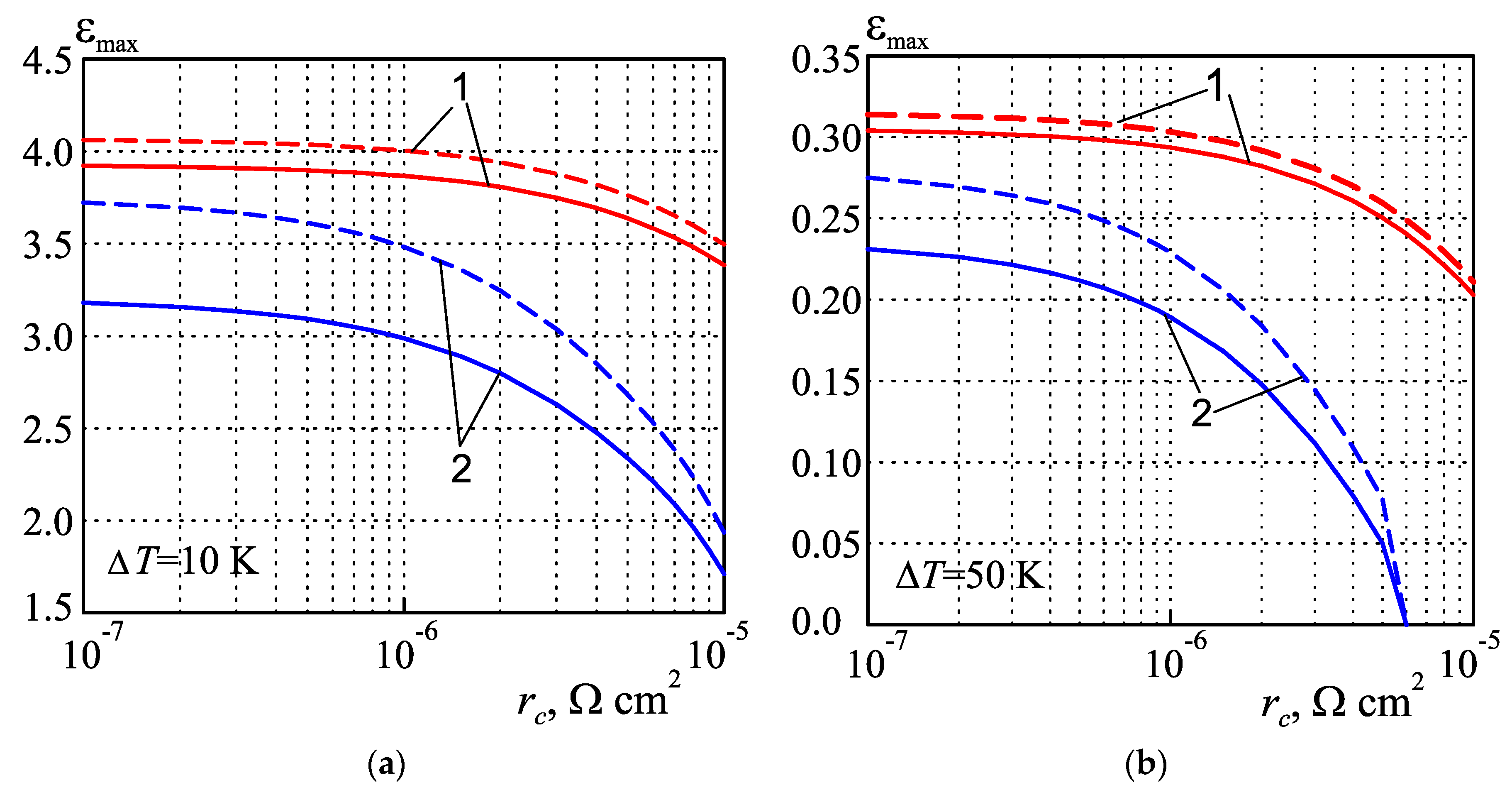
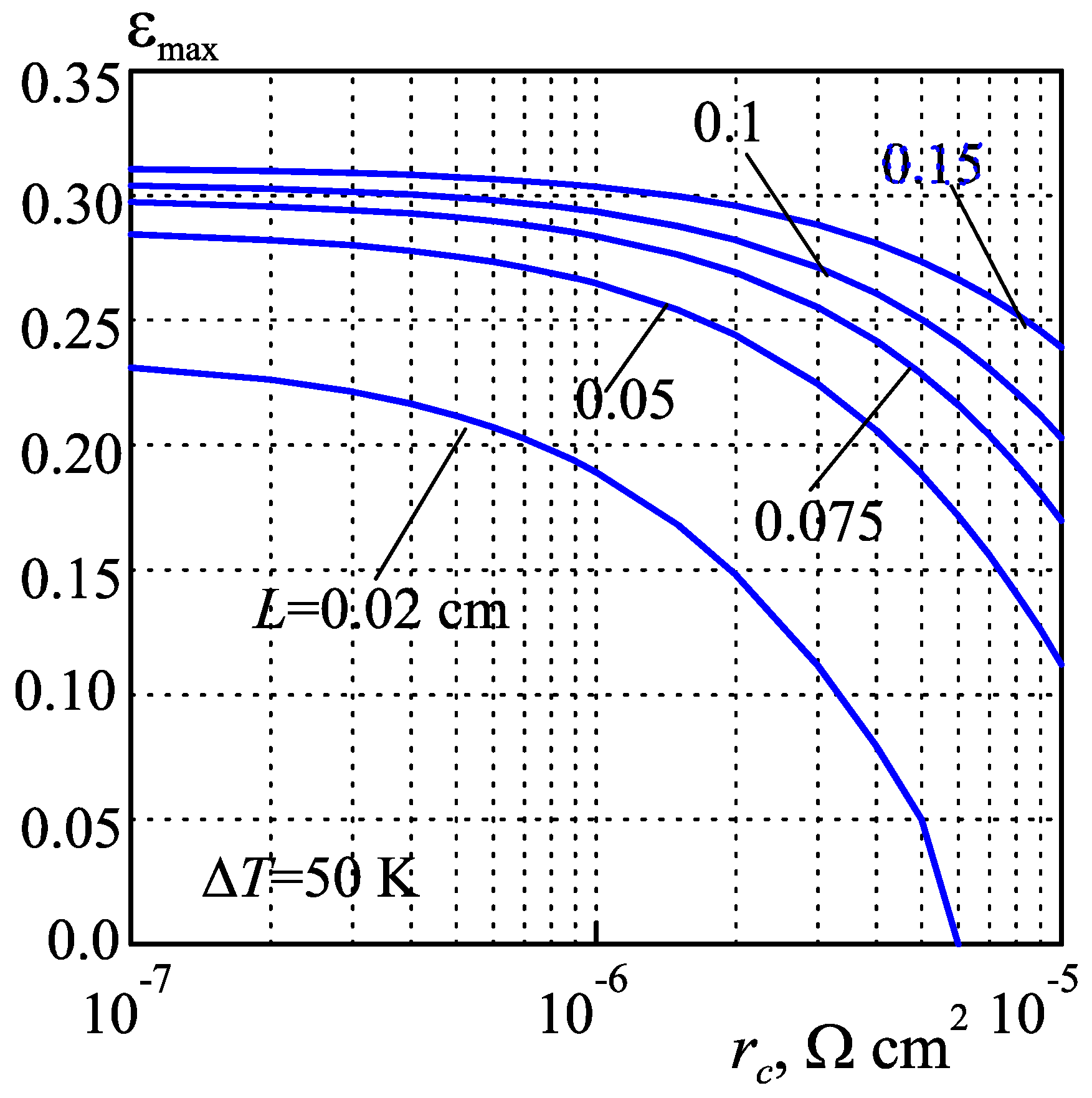
4.1. Cooling Converter

The dependences of the maximum COP εmax on a thermoelement length, calculated for temperature differences across the modules of 30 K and 50 K, are shown in Figure 5.
To analyze the impact of electrical contact resistance on the maximum COP, calculations were performed for two values of resistivity rc, namely, for the value rc = 5 × 10⁻⁶ Ω cm2, which is considered as typical for commercial TE modules [51], and for the minimum value rc = 10−7 Ω cm2. As shown in [58,76], such minimum contact resistance is caused by a potential barrier at the boundary between the TEM and the nickel anti-diffusion layer. As it follows from the data in Table 2, the lowest value of contact resistivity measured experimentally is close to 10−7 Ω cm2.
The effect of the thermal resistance of interconnectors and insulating plates results in the dependence of εmax on a thermoelement length for both the minimum (dashed lines in Figure 5) and the typical (solid lines in Figure 5) values of contact resistance. Reducing the leg length of module leads to a decrease in the COP, which is especially sharp if the length is less than 0.05 cm and the contact resistance is high.
Thermal resistance evokes the unwanted temperature drops δT across the interconnectors and insulating plates (Figure 6), which for modules with miniscale thermoelements, are the greater the shorter the leg.
Obviously, δTh across the heat-releasing (solid lines in Figure 6) insulating plate is significantly greater than the drop δTc across the heat-absorbing one (dashed lines in Figure 6). The larger the temperature difference across the module and the thermal resistance of the insulating plates, the greater δT. For example, for modules with a leg length of 0.02 cm and insulating plates made of Al2O3, δTh reaches a value of 3.5 K (Figure 6b) for a temperature difference across the module of ΔT = 50 K. Accordingly, the temperature of heat-releasing junctions of thermocouples increases by the same value, thus causing a reduction of the COP.
An improvement in the COP can be obtained by decreasing the thermal resistance of insulating plates. This is achieved by reducing the plate thickness and using ceramics with high thermal conductivity, such as AlN or pressed diamond powder. In particular, for insulating plates made of AlN, the temperature drop δTh has a value of less than 1 K instead of 3.5 K (Figure 6). In general, the temperature losses δTh for miniature modules with Al2O3 insulating plates are about 3.5 times or 8 times higher than δTh for modules with AlN or pressed diamond ceramics, respectively.
However, the data in Figure 5 show that the COP of modules with diamond insulating plates does not differ significantly from the COP of modules with AlN ceramics. Therefore, it is impractical to use materials with a thermal conductivity greater than that of aluminum nitride for insulating plates. In particular, using an expensive diamond ceramic is not reasonable. However, when choosing the material for insulating plates and plate thickness, the mechanical properties of the ceramics must be also taken into account.
We also studied the effect of interconnector electrical resistance on the COP of miniature modules. The optimal supply current for such modules usually does not exceed 3 A [49], and the Joule heat that is released in the interconnector has little effect on the COP.
Figure 7 shows the dependences of the COP εmax on the temperature difference ΔT across the miniscale module with the leg length of L = 0.02 cm. The COP has been calculated for different electrical and thermal resistances of contacts and insulating plates. This figure also represents the dependence ε0T), corresponding to the ideal model of the module (without undesirable electrical and thermal resistances). It can be seen that the COP εmax approaches the value ε0 of an ideal model, only if the contact electrical resistance is minimal and the insulating plates are made of materials with high thermal conductivity. Otherwise, εmax of the miniature module is 2–6 times less than the value of ε0. This result follows from the data of calculating the ratio ε0max presented in Table 4.
The analysis of these data also shows that a significant improvement in the COP of miniscale modules can be achieved by decreasing the electrical contact resistance to its rational value. An increase in the COP by reducing the thermal resistance of insulating plates is less noticeable.
To determine the rational values, the dependences of the maximum COP on the contact resistivity were calculated and analyzed. The results are shown in Figure 8 for the temperature differences of ΔT = 10 K and ΔT = 50 K. The data were calculated for cooling converters with a typical leg length of 0.1 cm and with miniature legs of 0.02 cm. Modules with the insulating plates of both Al2O3 and AlN materials were considered.
The value of the contact resistance strongly affects the COP. The lower the contact resistance, the higher the COP of converter. This dependence is more intense for a converter with miniature legs. In particular, for a converter with a thermoelement length of 0.02 cm, the COP at ΔT = 50 K decreases to zero (Figure 8b) if the contact resistivity exceeds the value of 5·10−6 Ω·cm2. This means that the maximum temperature difference of such a converter reaches only 50 K.
However, the data in Figure 8 show that for a converter with a certain length of thermoelements, there is a rational value rc opt of the contact resistivity, such that for r c < r c   o p t the increase in the COP becomes insignificant, namely, not exceeding 5%. The results of computer calculations have shown that the rational value of rc opt depends only on the length of the converter legs and does not depend either on the temperature drop in the converter or on the thermal resistance of the insulating plates. To determine the value of rc opt, we calculated the dependences εmax(rc) for converters with different leg lengths. They are shown in Figure 9. It can be seen that for each length there is its own value rc opt of contact resistivity, such that for r c < r c   o p t the dependences εmax(rc) go into saturation. The rational values rc opt have been defined for cooling converters with different leg lengths and are given in Table 5.
It is necessary to focus on such rational values of contact resistance in the development of technology for creating the junction between Bi2Te3–based material and anti-diffusion metal for cooling modules, especially for the modules with miniscale thermoelements.

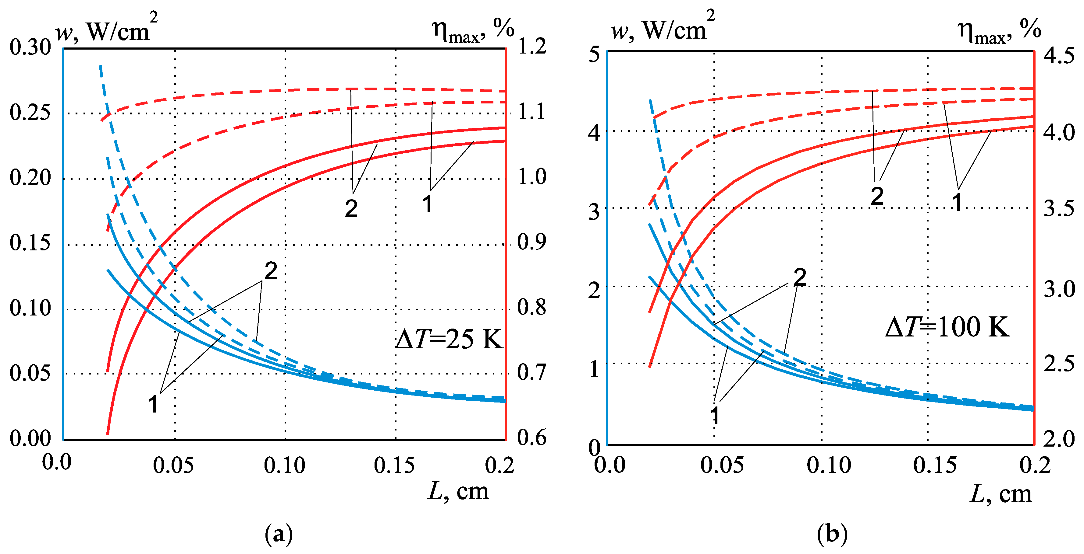
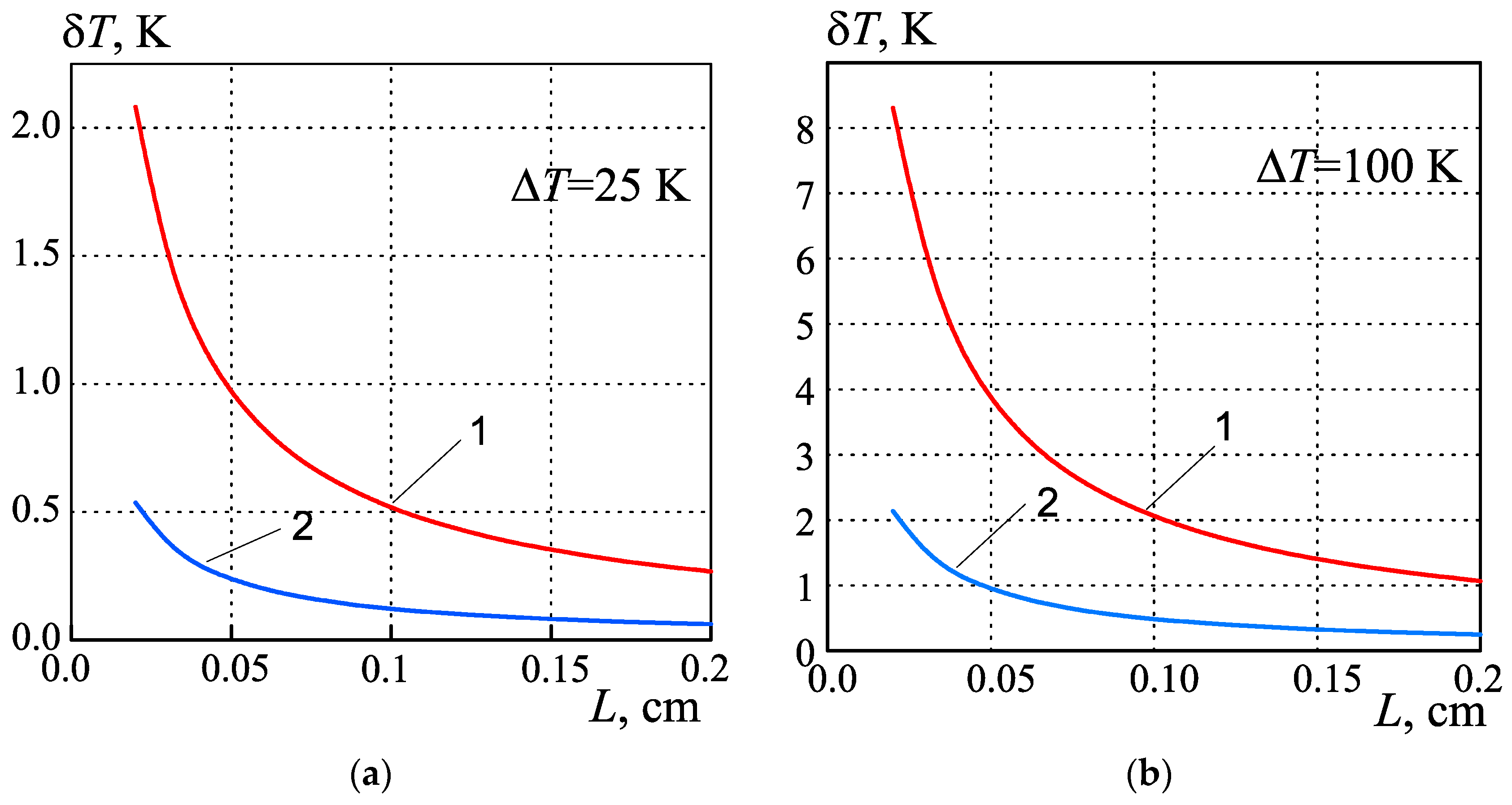
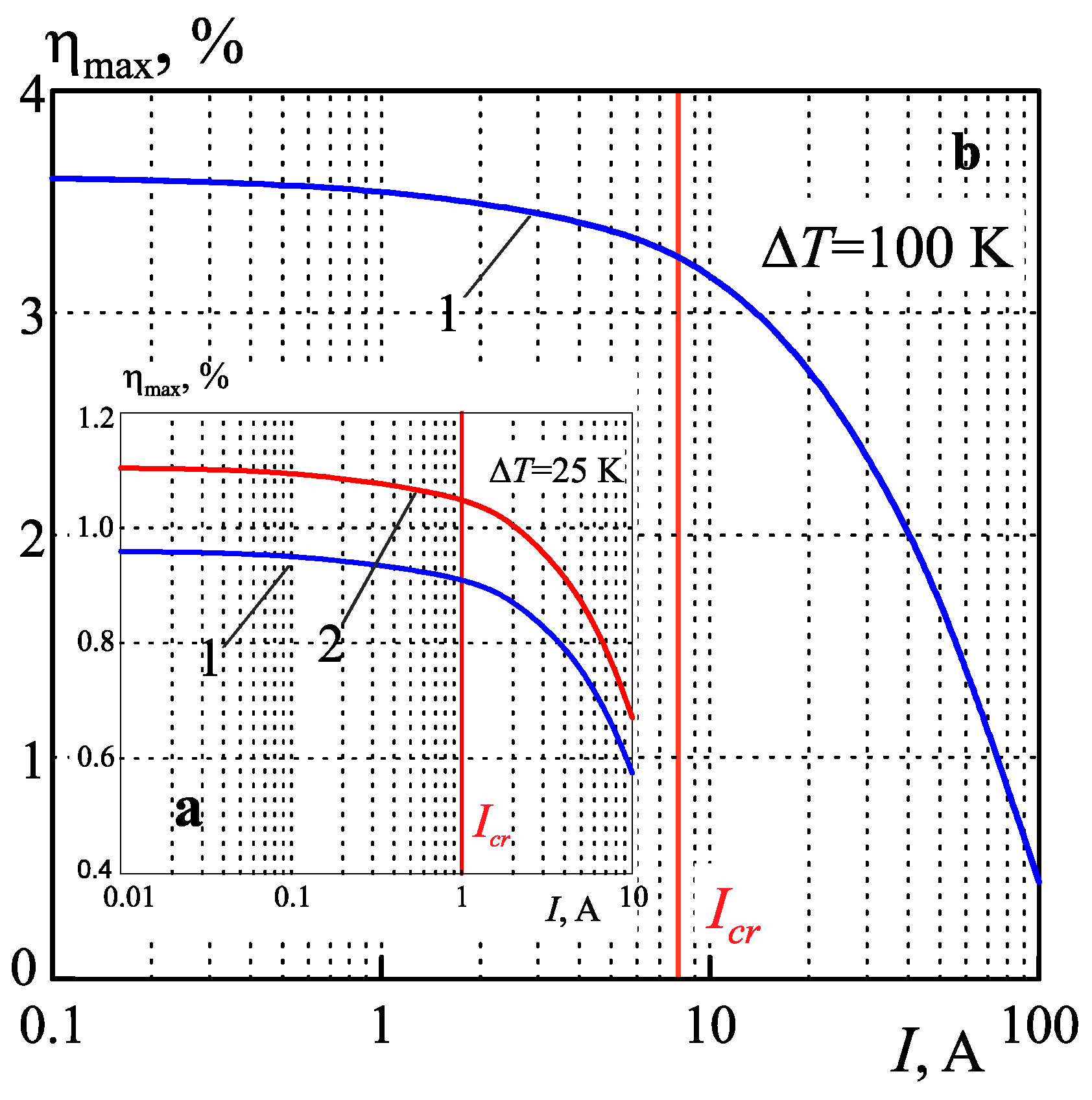
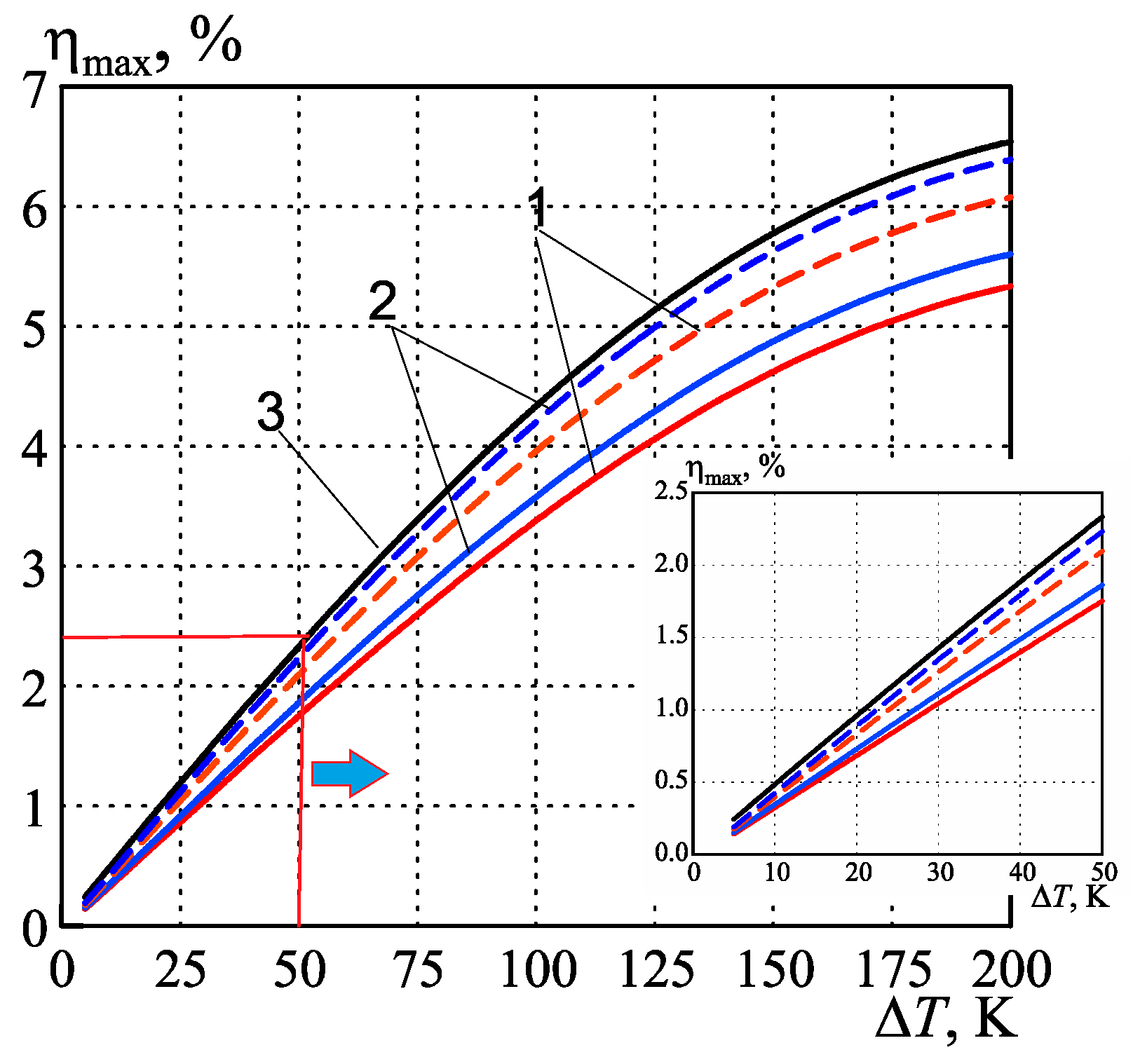
4.2. Generating Converter

The influence of electrical and thermal resistances of contacts, interconnectors and insulating plates on the efficiency and power density was studied for generating converters. Dependences of the maximum efficiency ηmax and power density w on the leg length, calculated for temperature drops of 25 K and 100 K on the generating module are shown in Figure 10. Reducing the length of the thermoelements leads to a decrease in efficiency, which is especially sharp if the length is less than 0.1 cm and the contact resistance is high. It is obvious that with a decrease in the leg length, the density of the generated power increases. This testifies to the absolute advantage of converters with miniature thermoelements. However, unwanted electrical and thermal resistances significantly affect this advantage, reducing the power density.
Thermal resistance causes a temperature drop δT across the insulating plates, which depends on the leg length and the temperature difference across the converter, as shown in Figure 11. In a module with miniature legs, the drop δT can reach a high value. For example, for a module with insulating plates made of Al2O3, δT = 8.5 K (Figure 11). Because of the generating module δ T h δ T c , the losses of the temperature difference across the module, in this case, are about 17 K, which results in a significant reduction in efficiency.
We also investigated the influence of copper interconnectors on the performance of the generating converter. Their thermal resistance actually does not affect the efficiency. However, their electrical resistance can affect the efficiency if the module is designed for a load with a large input current. The dependence of efficiency on the current in the thermoelectric circuit is shown in Figure 12. If the current is low, the Joule heat released in the interconnector has little effect on the efficiency. However, if the current exceeds a certain critical value of Icr, the efficiency decreases sharply. The value Icr depends on the temperature drop across the converter and does not depend on the leg length. In order to avoid a decrease in efficiency at high currents, it is enough to increase the thickness of the interconnector. This is confirmed by the dependences ηmax(lcon) at the high currents shown in Figure 13.
Dependences of maximum efficiency ηmax on the temperature drop ΔT across the module with the miniature legs are shown in Figure 14. Dependence η0T) for the ideal module model (without undesirable electrical and thermal resistances) is also given. The calculated ratio η0max is presented in Table 6. The ratio w0/w of power density values is also shown in this Table.
It can be seen that the efficiency ηmax approaches the value η0 for the modules with the contact resistivity of 10−7 Ω cm2 and insulating plates made of AlN. Otherwise ηmax of the miniscale converters is 1.5–2 times less than the value of η0. The power density w is 2.0–2.5 times less than its ideal value w0.
For the generating converter, as well as for the cooling module, there is a rational value rc opt of the contact resistance, such that for r c < r c   o p t the increase in the efficiency does not exceed 5%. Figure 15 shows the dependences of ηmax(rc), which were used to determine the values of rc opt for generator converters with different leg lengths. The results are presented in Table 7.
These contact resistance values should be adhered to when developing the technology of miniscale generator modules.
It should be noted that the calculated rational values of the contact resistivity, which for miniscale converters with leg lengths from 0.05 cm to 0.02 cm are in the range from 10−6 Ω·cm2 to 3·10−7 Ω·cm2, correlate well with the experimental values given in [51] and shown in Table 2. The technology for the fabrication of such contacts is described in detail in [51]. The manufacturing technique of miniscale modules with legs from 0.05 cm to 0.02 cm long has also been developed [49]. It is similar to the technology of modules with traditional leg lengths from 0.1 cm to 0.2 cm. Therefore, it can be confidently stated that there are no obstacles to the mass production of highly efficient miniature converters. The COP or efficiency of such converters will not be less than that of modules with traditional leg lengths. However, the consumption of thermoelectric materials for them will be significantly less, which makes them cheaper.

5. Conclusions

According to the results of the investigation, the following conclusions can be drawn:
  • A new numerical method is proposed for designing cooling modules in the maximum COP mode and generating modules with maximum efficiency, with regard to the electrical and thermal resistances of contacts, interconnectors, insulating plates and other factors. The negative effect of these undesirable resistances on the performance of miniscale converters has been estimated. The results prove that the electrical contact resistance becomes the predominant reason for the decrease in the efficiency of converters at the miniaturization of thermoelements.
  • A commercial Bi2Te3-based module has insulating plates made of Al2O3 material and a contact resistivity of about 5 × 10⁻⁶ Ω cm2. The maximum COP of such a cooling module with a leg length of 0.02 cm is about 2–6 times (depending on temperature drop) less than its possible value for the ideal model of the module (without undesirable electrical and thermal resistances). The efficiency of such modules for generators is about 1.5–2 times less as compared to the ideal model.
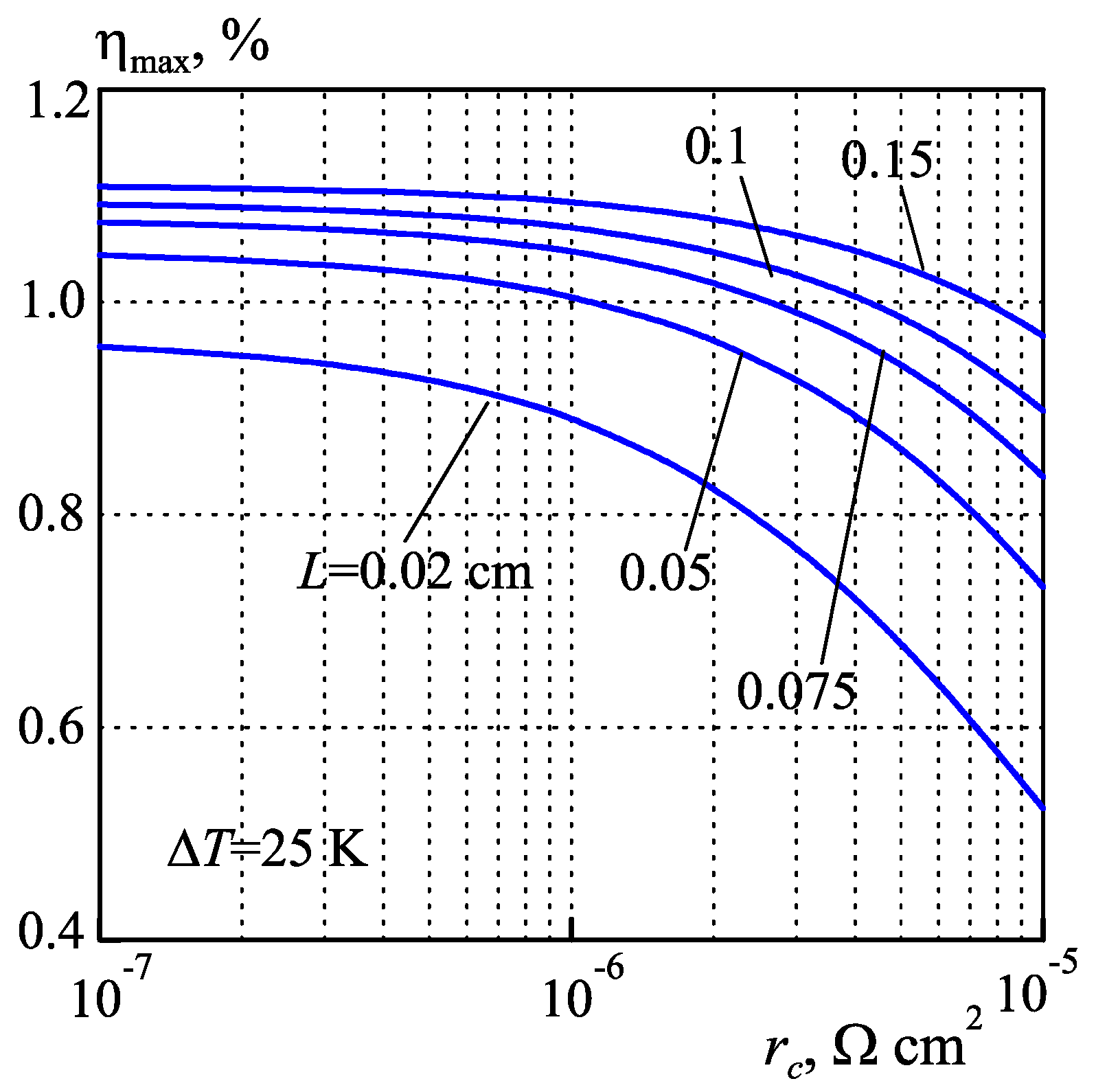
  • An improvement in the energy efficiency of miniature modules is achieved by decreasing the undesirable resistances to their limit values. Such a limit for the electrical contact resistance is its rational value, which depends on thermoelement length. The rational values for the Bi2Te3-based modules both for cooling and generation have been determined and are given in this paper. For miniscale converters with leg lengths from 0.05 cm to 0.02 cm, they vary in the range from 10−6 Ω·cm2 to 3·10−7 Ω·cm2 and correlate well with the experimental data obtained in [51]. It is expedient to follow these rational values of contact resistance in the fabrication of miniature modules. To reduce the undesirable thermal resistance, it is preferable to use AlN ceramics instead of insulating plates made of Al2O3.

Author Contributions

Conceptualization, L.V.; methodology, L.V.; investigation, L.V.; formal analysis, L.V.; visualization, L.V.; data curation, L.V.; writing—original draft preparation, L.V.; writing—review and editing, L.V.; software, M.K.; validation, M.K. All authors have read and agreed to the published version of the manuscript.

Funding

This paper is part of a research project funded by the National Academy of Sciences of Ukraine (project number 0122U000410).

Data Availability Statement

The data used in this manuscript are available upon reasonable request from the corresponding author.

Acknowledgments

The authors thank the Academician of the National Academy of Sciences of Ukraine Anatychuk L.I. for fruitful discussions of the research results.

Conflicts of Interest

The authors declare no conflict of interest.

References

  1. Champier, D. Thermoelectricity Engineering (Modules, Performance, Applications). 2019. Available online: https://hal.archives-ouvertes.fr/hal-02367539 (accessed on 23 March 2023).
  2. Thermoelectric Modules Market. Available online: https://www.maximizemarketresearch.com/market-report/thermoelectric-modules-market/2622/ (accessed on 23 March 2023).
  3. Dzumedzey, R.O.; Boryk, V.V. Performance specifications of thermoelectric modules on the example of the system “solar collector–thermoelectric generator”. Phys. Chemistry Solid State 2013, 14, 659–661. Available online: http://page.if.ua/uploads/pcss/vol14/!1403-35.pdf (accessed on 23 March 2023).
  4. Selenium and Tellurium Statistics and Information. Available online: https://www.usgs.gov/centers/national-minerals-information-center/selenium-and-tellurium-statistics-and-information (accessed on 23 March 2023).
  5. Zhao, D.; Tan, G. A review of thermoelectric cooling: Materials, modeling and applications. Appl. Therm. Eng. 2014, 66, 15–24. [Google Scholar] [CrossRef]
  6. Nolas, G.S.; Morelli, D.T.; Tritt, T.M. Skutterudites: A phonon-glass-electron crystal approach to advanced thermoelectric energy conversion applications. Annu. Rev. Mater. Sci. 1999, 29, 89–116. [Google Scholar] [CrossRef]
  7. Shevelkov, A.V.; Kovnir, K. Zintl clathrates. In Zintl Phases; Fassler, T.F., Ed.; Springer: Berlin/Heidelberg, Germany, 2011; pp. 97–142. [Google Scholar] [CrossRef]
  8. Shi, X.; Chen, L.; Uher, C. Recent advances in high performance bulk thermoelectric materials. Int. Mater. Rev. 2016, 61, 379–415. [Google Scholar] [CrossRef]
  9. Shi, X.; Yang, J.; Salvador, J.R.; Chi, M.; Cho, Y.J.; Wang, H.; Bai, S.; Yang, J.; Zhang, W.; Chen, L. Multiple-filled skutterudites: High thermoelectric figure of merit through separately optimizing electrical and thermal transports. J. Am. Chem. Soc. 2011, 133, 7837–7846. [Google Scholar] [CrossRef] [PubMed]
  10. Morelli, D.T.; Meisner, G.P.; Chen, B.X.; Hu, S.Q.; Uher, C. Cerium filling and doping of cobalt triantimonide. Phys. Rev. B 1997, 56, 7376–7383. [Google Scholar] [CrossRef]
  11. Saramat, A.; Svensson, G.; Palmqvist, A.E.C.; Stiewe, C.; Mueller, E.; Platzek, D.; Williams, S.G.K.; Rowe, D.M.; Bryan, J.D.; Stucky, G.D. Large thermoelectric figure of merit at high temperature in Czochralski-grown clathrate Ba8Ga16Ge30. J. Appl. Phys. 2006, 99, 023708. [Google Scholar] [CrossRef]
  12. You, S.W.; Shin, D.K.; Ur, S.C.; Kim, I.H. Solid-state synthesis and thermoelectric properties of Mg2Si0.5Ge0.5Sbm. J. Electron. Mater. 2015, 44, 1504–1508. [Google Scholar] [CrossRef]
  13. Zhang, Q.; He, J.; Zhu, T.J.; Zhang, S.N.; Zhao, X.B.; Tritt, T.M. High figures of merit and natural nanostructures in Mg2Si0.4Sn0.6 based thermoelectric materials. Appl. Phys. Lett. 2008, 93, 102109. [Google Scholar] [CrossRef]
  14. Khan, A.U.; Vlachos, N.V.; Hatzikraniotis, E.; Polymeris, G.S.; Lioutas, C.B.; Stefanaki, E.C.; Paraskevopoulos, K.M.; Giapintzakis, I.; Kyratsi, T. Thermoelectric properties of highly efficient Bi-doped Mg2Si1−x−ySnxGey materials. Acta Mater. 2014, 77, 43–53. [Google Scholar] [CrossRef]
  15. Aoyama, I.; Fedorov, M.I.; Zaitsev, V.K.; Solomkin, F.Y.; Eremin, I.S.; Samunin, A.Y.; Mukojima, M.; Sano, S.; Tsuji, T. Effects of Ge doping on micromorphology of MnSi in MnSi∼1.7 and on their thermoelectric transport properties. Jpn. J. Appl. Phys. 2005, 44, 8562–8570. [Google Scholar] [CrossRef]
  16. Aoyama, I.; Kaibe, H.; Rauscher, L.; Kanda, T.; Mukojima, M.; Sano, S.; Tsuji, T. Doping effects on thermoelectric properties of higher manganese silicides (HMSs, MnSi1.74) and characterization of thermoelectric generating module using p-type (Al, Ge and Mo)-doped HMSs and n-type Mg2Si0.4Sn0.6 legs. Jpn. J. Appl. Phys. 2005, 44, 4275–4281. [Google Scholar] [CrossRef]
  17. Pedersen, B.L.; Iversen, B.B. Thermally stable thermoelectric Zn4Sb3 by zone-melting synthesis. Appl. Phys. Lett. 2008, 92, 161907. [Google Scholar] [CrossRef]
  18. Rhyee, J.-S.; Kim, H. Chemical potential tuning and enhancement of thermoelectric properties in indium selenides. Materials 2015, 8, 1283–1324. [Google Scholar] [CrossRef] [PubMed]
  19. Bottner, H.; Nurnus, J.; Schubert, A. Miniaturized thermoelectric converters. In Thermoelectrics Handbook: Macro to Nano; Rowe, D.M., Ed.; Taylor & Francis: London, UK, 2006; pp. 1–16. Available online: https://www.taylorfrancis.com/chapters/mono/10.1201/9781420038903-46/miniaturized-thermoelectric-converters-rowe (accessed on 23 March 2023).
  20. Sarbu, I.; Dorca, A. A comprehensive review of solar thermoelectric cooling systems. Int. J. Energy Res. 2018, 42, 395–415. [Google Scholar] [CrossRef]
  21. Salah, W.A.; Abuhelwa, M. Review of thermoelectric cooling devices recent applications. J. Eng. Sci. Technol. 2020, 15, 455–476. [Google Scholar]
  22. Sharp, J.; Bierschenk, J.; Lyon, H.B. Overview of solid-state thermoelectric refrigerators and possible applications to on-chip thermal management. Proc. IEEE 2006, 94, 1602–1612. [Google Scholar] [CrossRef]
  23. Redmond, M.; Kumar, S. Optimization of thermoelectric coolers for hotspot cooling in three-dimensional stacked chips. J. Electron. Packag. 2015, 137, 011006. [Google Scholar] [CrossRef]
  24. Bar-Cohen, A.; Wang, P. On-chip hot spot remediation with miniaturized thermoelectric coolers. Microgravity Sci. Technol. 2009, 21 (Suppl. S1), S351–S359. [Google Scholar] [CrossRef]
  25. Wang, J.; Zhao, X.-J.; Cai, Y.-J.; Zhang, C.; Bao, W.-W. Experimental study on the thermal management of high-power LED headlight cooling device integrated with thermoelectric cooler package. Energy Convers. Manag. 2015, 101, 532–540. [Google Scholar] [CrossRef]
  26. Li, J.; Ma, B.; Wang, R.; Han, L. Study on a cooling system based on thermoelectric cooler for thermal management of high-power LEDs. Microelectron. Reliab. 2011, 51, 2210–2215. [Google Scholar] [CrossRef]
  27. Qin, H.; Zhong, D.; Wang, C.H. Thermal performance evaluation and economic analysis of LED integrated with thermoelectric cooler package. Adv. Mater. Res. 2011, 216, 106–110. [Google Scholar] [CrossRef]
  28. Shen, L.; Chen, H.; Xiao, F.; Yang, Y.; Wang, S. The step-change cooling performance of miniature thermoelectric module for pulse laser. Energy Convers. Manag. 2014, 80, 9–45. [Google Scholar] [CrossRef]
  29. Zhang, W.; Shen, L.; Yang, Y.; Chen, H. Thermal management for a micro semiconductor laser based on thermoelectric cooling. Appl. Therm. Eng. 2015, 90, 664–673. [Google Scholar] [CrossRef]
  30. Piotrowski, A.; Piotrowski, J.; Gawron, W.; Pawluczyk, J.; Pedzinska, M. Extension of usable spectral range of Peltier cooled photodetectors. Acta Phys. Pol. A 2009, 116, s52–s55. [Google Scholar] [CrossRef]
  31. Anatychuk, L.I.; Vikhor, L.M. The limits of thermoelectric cooling for photodetectors. J. Thermoelectr. 2013, 5, 54–58. [Google Scholar]
  32. Nordin, L.; Muhowski, A.J.; Wasserman, D. High operating temperature plasmonic infrared detectors. Appl. Phys. Lett. 2022, 120, 101103. [Google Scholar] [CrossRef]
  33. Parashchuk, T.; Sidorenko, N.; Ivantsov, L.; Sorokin, A.; Maksymuk, M.; Dzundza, B.; Dashevsky, Z. Development of a solid-state multi-stage thermoelectric cooler. J. Power Sources 2021, 496, 229821. [Google Scholar] [CrossRef]
  34. Vullers, R.J.M.; Schaijk, R.; Visser, H.J.; Penders, J.; Hoof, C.V. Energy Harvesting for Autonomous Wireless Sensor Networks. IEEE Solid State Circuits Mag. 2010, 2, 29–38. [Google Scholar] [CrossRef]
  35. Dunham, M.T.; Barako, M.T.; LeBlanc, S.; Asheghi-Roudheni, M.; Chen, B.; Goodson, K. Modeling and Optimization of Small Thermoelectric Generators for Low-Power Electronics. In Proceedings of the ASME 2013 International Technical Conference and Exhibition on Packaging and Integration of Electronic and Photonic Microsystems, Burlingame, CA, USA, 16–18 July 2013; Volume 1. [Google Scholar] [CrossRef]
  36. Parsonnet, V. A Lifetime Pacemaker Revisited. N. Engl. J. Med. 2007, 357, 2638–2639. [Google Scholar] [CrossRef]
  37. Scott, A.; Whalen, C.A.; Apblett, T.L. Improving power density and efficiency of miniature radioisotopic thermoelectric generators. J. Power Sources 2008, 180, 657–663. [Google Scholar] [CrossRef]
  38. Leonov, V.; Vullers, R. Wearable electronics self-powered by using human body heat: The state of the art and the perspective. J. Renew. Sustain. Energy 2009, 1, 62701. [Google Scholar] [CrossRef]
  39. Hong, S.; Gu, Y.; Seo, J.K.; Wang, J.; Liu, P.; Shirley Meng, Y.; Xu, S.; Chen, R. Wearable thermoelectrics for personalized thermoregulation. Sci. Adv. 2019, 5, eaaw0536. [Google Scholar] [CrossRef]
  40. Wei, R.; Sun, Y.; Zhao, D.; Aili, A.; Zhang, S.; Shi, C.; Zhang, J.; Geng, H.; Zhang, J.; Zhang, L.; et al. High-performance wearable thermoelectric generator with self-healing, recycling, and Lego-like reconfiguring capabilities. Sci. Adv. 2021, 7, eabe0586. [Google Scholar] [CrossRef]
  41. Torfs, T.; Leonov, V.; Vullers, R. Pulse oximeter fully powered by human body heat. Sens. Transducers J. 2007, 80, 1230–1238. [Google Scholar]
  42. Van Bavel, M.; Leonov, V.; Yazicioglu, R.F.; Torfs, T.; van Hoof, C.; Posthuma, N.; Vullers, R. Wearable battery-free wireless 2-channel EEG systems powerd by energy scavengers. Sens. Transducers J. 2008, 94, 103–115. [Google Scholar]
  43. Kim, C.S.; Yang, H.M.; Lee, J.; Lee, G.S.; Choi, H.; Kim, Y.J.; Lim, S.H.; Cho, S.H.; Cho, B.J. Self-powered wearable electrocardiography using a wearable thermoelectric power generator. ACS Energy Lett. 2018, 3, 501–507. [Google Scholar] [CrossRef]
  44. Leonov, V.; Torfs, T.; van Hoof, C.; Vullers, R.J. Smart wireless sensors integrated in clothing: An electrocardiography system in a shirt powered using human body heat. Sens. Transducers J. 2009, 107, 165. [Google Scholar]
  45. Vondrak, J.; Schmidt, M.; Proto, A.; Penhaker, M.; Jargus, J.; Peter, L. Using Miniature Thermoelectric Generators for Wearable Energy Harvesting. In Proceedings of the 2019 4th International Conference on Smart and Sustainable Technologies (SpliTech), Split, Croatia, 18–21 June 2019; pp. 1–6. [Google Scholar] [CrossRef]
  46. Xu, Q.; Deng, B.; Zhang, L.; Lin, S.; Han, Z.; Zhou, Q.; Li, J.; Zhu, Y.; Jiang, F.; Li, Q.; et al. High-performance, flexible thermoelectric generator based on bulk materials. Cell Rep. Phys. Sci. 2022, 3, 100780. [Google Scholar] [CrossRef]
  47. Bahk, J.-H.; Fang, H.; Yazawa, K.; Shakouri, A. Flexible thermoelectric materials and device optimization for wearable energy harvesting. J. Mater. Chem. C 2015, 3, 10362–10374. [Google Scholar] [CrossRef]
  48. Du, Y.; Xu, J.; Paul, B.; Eklund, P. Flexible thermoelectric materials and devices. Appl. Mater. Today 2018, 12, 366–388. [Google Scholar] [CrossRef]
  49. Semenyuk, V.A. Thermoelectric Cooling of Electro-Optic Components. In Thermoelectrics Handbook: Macro to Nano; Rowe, D.M., Ed.; Taylor & Francis: London, UK, 2006; pp. 1–20. [Google Scholar] [CrossRef]
  50. Anatychuk, L.I. Thermoelectricity. Volume 2. Thermoelectric Energy Convertors; Institute of Thermoelectricity: Chernivtsi, Ukraine, 2003; Available online: http://library.lol/main/9D47871457FBA3B0F47B88ACB76589E1 (accessed on 23 March 2023).
  51. Taylor, P.J.; Maddux, J.R.; Meissner, G.; Venkatasubramanian, R.; Bulman, G.; Pierce, J.; Gupta, R.; Bierschenk, J.; Caylor, C.; D’Angelo, J.; et al. Controlled improvement in specific contact resistivity for thermoelectric materials by ion implantation. Appl. Phys. Lett. 2013, 103, 043902. [Google Scholar] [CrossRef]
  52. Ioffe, A.F. Semiconductor Thermoelements and Thermoelectric Cooling; Infoserch Limited: London, UK, 1957; Available online: http://library.lol/main/957FA64C64DACD34F22E31B2035B549B (accessed on 23 March 2023).
  53. Chen, L.; Mei, D.; Wang, Y.; Li, Y. Ni barrier in Bi2Te3-based thermoelectric modules for reduced contact resistance and enhanced power generation properties. J. Alloys Compd. 2019, 796, 314–320. [Google Scholar] [CrossRef]
  54. Joshi, G.; Mitchell, D.; Ruedin, J.; Hoover, K.; Guzman, R.; McAleer, M.; Wood, L.; Savoy, S. Pulsed-light surface annealing for low contact resistance interfaces between metal electrodes and bismuth telluride thermoelectric materials. J. Mater. Chem. C 2019, 7, 479–483. [Google Scholar] [CrossRef]
  55. Gupta, R.P.; Xiong, K.; White, J.B.; Cho, K.; Alshareef, H.N.; Gnade, B.E. Low Resistance Ohmic Contacts to Bi2Te3 Using Ni and Co Metallization. J. Electrochem. Soc. 2010, 157, H666. [Google Scholar] [CrossRef]
  56. Gupta, R.P.; McCarty, R.; Sharp, J. Practical contact resistance measurement method for bulk Bi2Te3 based thermoelectric devices. J. Electron. Mater. 2014, 43, 1608–1612. [Google Scholar] [CrossRef]
  57. Kuznetsov, G.D.; Polystanskiy, Y.G.; Evseev, V.A. The metallization of the thermoelement branches by ionic sputtering of the nickel and cobalt. In Proceedings of the XIV International Conference on Thermoelectrics, St. Petersburg, Russia, 27–30 June 1995; pp. 166–167. Available online: https://books.google.com.ua/books/about/Proceedings_of_the_XIV_International_Con.html?id=P7jrAQAACAAJ&redir_esc=y (accessed on 23 March 2023).
  58. Vikhor, L.M.; Anatychuk, L.I.; Gorskyi, P.V. Electrical resistance of metal contact to Bi2Te3 based thermoelectric legs. J. Appl. Phys. 2019, 126, 164503. [Google Scholar] [CrossRef]
  59. Gupta, R.; White, J.; Iyore, O.; Chakrabati, U.; Alshareef, H.; Gnade, B. Determination of contact resistivity by the Cox and Strack method for metal contacts to bulk bismuth antimony telluride. Electrochem. Solid State Lett. 2009, 12, H302–H304. [Google Scholar] [CrossRef]
  60. Min, G.; Rowe, D.M. Improved model for calculating the coefficient of performance of a Peltier module. Energy Convers. Manag. 2000, 41, 163–171. [Google Scholar] [CrossRef]
  61. Xuan, X.C. Investigation of thermal contact effect on thermoelectric coolers. Energy Convers. Manag. 2003, 44, 399–410. [Google Scholar] [CrossRef]
  62. Gou, X.; Xiao, H.; Yang, S. Modeling, experimental study and optimization on low-temperature waste heat thermoelectric generator system. Appl. Energy 2010, 87, 3131–3136. [Google Scholar] [CrossRef]
  63. Shen, Z.-G.; Wu, S.-Y.; Xiao, L.; Yin, G. Theoretical modeling of thermoelectric generator with particular emphasis on the effect of side surface heat transfer. Energy 2016, 95, 367–379. [Google Scholar] [CrossRef]
  64. He, H.; Liu, W.; Wu, Y.; Rong, M.; Zhao, P.; Tang, X. An approximate and efficient characterization method for temperature-dependent parameters of thermoelectric modules. Energy Convers. Manag. 2019, 180, 584–597. [Google Scholar] [CrossRef]
  65. He, H.; Wu, Y.; Liu, W.; Rong, M.; Fang, Z.; Tang, X. Comprehensive modeling for geometric optimization of a thermoelectric generator module. Energy Convers. Manag. 2019, 183, 645–659. [Google Scholar] [CrossRef]
  66. Montecucco, A.; Buckle, A.R.; Knox, V. Solution to the 1-D unsteady heat conduction equation with internal Joule heat generation for thermoelectric devices. Appl. Thermal Eng. 2012, 35, 177–184. [Google Scholar] [CrossRef]
  67. Huang, M.-J.; Yen, R.-H.; Wang, A.-B. The influence of the Thomson effect on the performance of a thermoelectric cooler. Int. J. Heat Mass Transfer. 2005, 48, 413–418. [Google Scholar] [CrossRef]
  68. Meng, F.; Chen, L.; Sun, F. A numerical model and comparative investigation of a thermoelectric generator with multi-irreversibilities. Energy 2011, 36, 3513–3522. [Google Scholar] [CrossRef]
  69. Chen, W.-H.; Liao, C.-Y.; Hung, C.-I. A numerical study on the performance of miniature thermoelectric cooler affected by Thomson effect. Appl. Energy 2012, 89, 464–473. [Google Scholar] [CrossRef]
  70. Zhu, W.; Deng, Y.; Wang, Y.; Wang, A. Finite element analysis of miniature thermoelectric coolers with high cooling performance and short response time. Microelectron. J. 2013, 44, 860–868. [Google Scholar] [CrossRef]
  71. Wang, X.-D.; Huang, Y.-X.; Cheng, C.-H.; Lin, D.T.-W.; Kang, C.-H. A three-dimensional numerical modeling of thermoelectric device with consideration of coupling of temperature field and electric potential field. Energy 2012, 47, 488–497. [Google Scholar] [CrossRef]
  72. Jang, B.; Han, S.; Kim, J.-Y. Optimal design for micro-thermoelectric generators using finite element analysis. Microelectron. Eng. 2011, 88, 775–778. [Google Scholar] [CrossRef]
  73. Wang, X.; Qi, J.; Deng, W.; Li, G.; Gao, X.; He, L.; Zhang, S. An optimized design approach concerning thermoelectric generators with frustum-shaped legs based on three-dimensional multiphysics model. Energy 2021, 233, 120810. [Google Scholar] [CrossRef]
  74. Anatychuk, L.I.; Havrylyuk, N.V.; Lysko, V.V. Methods and equipment for quality control of thermoelectric materials. J. Electron. Mater. 2012, 41, 1680–1685. [Google Scholar] [CrossRef]
  75. Anatychuk, L.I.; Havrylyuk, N.V.; Lysko, V.V. Absolute method for measuring of thermoelectric properties of materials. Mater. Today Proc. 2015, 2, 737–743. [Google Scholar] [CrossRef]
  76. Anatychuk, L.I.; Vikhor, L.M.; Mitskaniuk, N.V. Contact resistance due to potential barrier at thermoelectric material–metal boundary. J. Thermoelectr. 2019, 4, 74–88. [Google Scholar]
Figure 1. World market size (a) [1,2] and estimation of production volume (b) of thermoelectric modules.
Energies 16 04082 g001
Figure 2. Dependences of maximum efficiency η0 (a) and maximum COP ε0 (b) on a thermoelement length L for the value of contact resistivity rc = 5 × 10⁻⁶ Ω cm2.
Energies 16 04082 g002
Figure 3. Schematic of TE module (a) and thermocouple converter in cooling mode (b) or power generation mode (c). 1—heat-absorbing thermocouple junction, 2—metallic interconnector, 3—insulating plate, 4—contact zone.
Energies 16 04082 g003
Figure 4. Temperature dependences of the Seebeck coefficient α (a), the electrical conductivity σ (b), the thermal conductivity κ (c) and the figure of merit Z (d) of materials for cooling modules: 1—n-type Bi2Te2.7Se0.3, 2—p-type Bi0.5Sb1.5Te3 and alloys used for generating converters: 3—n-type (Bi2Te3)0.90(Sb2Te3)0.05(Sb2Se3)0.05, 4—p-type (Bi2Te3)0.25(Sb2Te3)0.72(Sb2Se3)0.03.
Energies 16 04082 g004aEnergies 16 04082 g004b
Figure 5. Dependences of the maximum COP εmax on the leg length L. Contact resistance: rc = 5 × 10⁻⁶ Ω cm2 (solid lines), rc = 10−7 Ω cm2 (dashed lines). Insulating plates: 1—Al2O3, 2—AlN and 3—pressed diamond powder. Temperature difference: ΔT = 30 K (a) and ΔT = 50 K (b). Th = 300 K.
Energies 16 04082 g005
Figure 6. Dependences of temperature drop δT across the heat-releasing (solid lines) and heat-absorbing (dashed lines) insulating plates on the leg length L. rc = 5 × 10⁻⁶ Ω cm2. Insulating plates: 1—Al2O3, 2—AlN and 3—pressed diamond powder. ΔT = 30 K (a), ΔT = 50 K (b), Th = 300 K.
Energies 16 04082 g006
Figure 7. Dependences of the maximum COP εmax on the temperature difference ΔT, at Th = 300 K. L = 0.02 cm, rc = 5 × 10⁻⁶ Ω cm2 (solid lines), rc = 10−7 Ω cm2 (dashed lines), insulating plates: 1—Al2O3, 2—AlN. 3—dependence ε0T) for the ideal model of module.
Energies 16 04082 g007
Figure 8. Dependences of the COP εmax on the contact resistivity rc for temperature differences ΔT = 10 K (a) and ΔT = 50 K (b). 1—leg length L = 0.1 cm, 2—L = 0.02 cm; insulating plates made of Al2O3 (solid lines) and AlN (dashed lines).
Energies 16 04082 g008
Figure 9. Dependences of COP εmax on the contact resistance rc for different leg lengths L. ΔT = 50 K, insulating plates made of Al2O3.
Energies 16 04082 g009
Figure 10. Dependences of the maximum efficiency ηmax and power density w on the leg length L. Contact resistance: rc = 5 × 10⁻⁶ Ω cm2 (solid lines), rc = 10−7 Ω cm2 (dashed lines). Insulating plates: 1—Al2O3, 2—AlN. Temperature difference: ΔT = 25 K (a), ΔT = 100 K (b). Tc= 300 K.
Energies 16 04082 g010
Figure 11. Dependences of temperature drop δT across the insulating plate on the leg length L. rc = 5 × 10⁻⁶ Ω cm2, insulating plate: 1—Al2O3, 2—AlN, ΔT = 25 K (a), ΔT = 100 K (b), Tc= 300 K.
Energies 16 04082 g011
Figure 12. Dependences of the efficiency ηmax on the current I in thermoelectric circuit. rc = 5 × 10⁻⁶ Ω cm2, AlN insulating plate, leg length 1—L = 0.05 cm, 2—L = 0.15 cm. ΔT = 25 K (a), ΔT = 100 K (b).
Energies 16 04082 g012
Figure 13. Dependences of the efficiency ηmax on the thickness of interconnector lcon. AlN insulating plates, rc = 5 × 10⁻⁶ Ω cm2, L = 0.05 cm. ΔT = 25 K and I = 10 A (a), ΔT = 100 K and I = 100 A (b). Tc= 300 K.
Energies 16 04082 g013
Figure 14. Dependences of maximum efficiency ηmax on the temperature difference ΔT, at Tc= 300 K. L = 0.05 cm, rc = 5 × 10⁻⁶ Ω cm2 (solid lines), rc = 10−7 Ω cm2 (dashed lines), insulating plates: 1—Al2O3, 2—AlN. 3—dependence η0T) for the ideal model of module.
Energies 16 04082 g014
Figure 15. Dependences of maximum efficiency ηmax on the contact resistivity rc for different leg length L. ΔT = 25 K, insulating plates made of Al2O3.
Energies 16 04082 g015
Table 1. Annual world production of tellurium and its price [4].
Year20152016201720182019202020212022
Production, tons400400420460520562610640
Price, $/kg7734407460566868
Table 2. Resistivity of TEM–metal contact.
ContactFeatures of Contact TechniqueContact Resistivity rc, Ω cm2Reference
Calculation data
p-type Bi2Te3/Ni-(3.0–3.2) × 10−6[57]
n-type Bi2Te2.7Se0.3/Ni,
p-type Bi0.5Sb1.5Te3/Ni
-(0.25–2.5) × 10−6[58]
Experimental data
p-type BiSbTe/Ni-3.7 × 10−6[59]
n-type Bi2Te2.7Se0.3/
anti-diffusion barrier
Fabrication of contact under the standard technology.
Improved technology of surface treatment and cleaning.
2.74 × 10⁻⁶
1.12 × 10⁻⁶
[56]
p-type Bi0.5Sb1.5Te3/
anti-diffusion barrier
Fabrication of contact under the standard technology.
Improved technology of surface treatment and cleaning.
3.59 × 10⁻⁶
1.3 × 10⁻⁶
[56]
n-type (Bi,Sb)2(Se,Te)3/NiProcessing and cleaning of the TEM surface.
Ion implantation of impurities for increasing the carrier concentration at the TEM–metal boundary.
1.7 × 10⁻⁶
4.5 × 10⁻⁷
[51]
p-type (Bi,Sb)2(Se,Te)3/NiProcessing and cleaning of the TEM surface.
Ion implantation of impurities for increasing the carrier concentration at the TEM–metal boundary.
7.7 × 10⁻⁷
2.7 × 10⁻⁷
[51]
Table 3. Value of parameters used for calculation.
ParameterValue
Leg length L, cm0.02–0.2
Ratio K c o n = s c o n / 2 s 1.25
Ratio K i n s = s i n s / 2 s 2.25
Thickness of the insulating plate lins, cm0.02
Thickness of the copper interconnector lcon, cm0.02
Current in a circuit I, A1.0
Thermal conductivity of insulating plate materials κins, W/cm K:
Al2O30.24
AlN1.25
Pressed diamond powder10.0
Table 4. Ratio ε0max of ideal module COP ε0 to real module COP εmax in dependence of thermoelement length.
Leg Length L, cmε0max
rc = 10−7 Ω cm2,
AlN Insulating Plates
ε0max
rc = 10−7 Ω cm2,
Al2O3 Insulating Plates
ε0max
rc = 5 × 10⁻⁶ Ω cm2,
AlN Insulating Plates
ε0max
rc = 5 × 10⁻⁶ Ω cm2,
Al2O3 Insulating Plates
Temperature difference across a module ΔT = 10 K, ε0 = 4.149
0.11.021.061.101.14
0.051.041.121.211.29
0.021.111.301.541.77
Temperature difference across a module ΔT = 30 K, ε0 = 0.961
0.11.021.051.141.17
0.051.041.101.291.35
0.021.111.261.852.11
Temperature difference across a module ΔT = 50 K, ε0 = 0.324
0.11.031.071.251.29
0.051.071.141.591.72
0.021.181.404.186.47
Table 5. The rational values of the contact resistivity for cooling converters with different leg lengths.
Thermoelement length
L, cm
0.150.10.0750.050.02
Rational contact resistivity
rc opt, Ω·cm2
2·10−610−69·10−77·10−73·10−7
Table 6. Ratio of efficiencies η0max and of power densities w0/w depending on thermoelement length.
Leg Length L, cmrc = 10−7Ω cm2,
AlN Insulating Plate
rc = 10−7Ω cm2,
Al2O3 Insulating Plate
rc = 5 × 10⁻⁶Ω cm2,
AlN Insulating Plate
rc = 5 × 10⁻⁶Ω cm2,
Al2O3 Insulating Plate
η0maxw0/wη0maxw0/wη0maxw0/wη0maxw0/w
Temperature difference across a module ΔT = 10 K, η0 = 0.4838
0.21.121.141.141.191.191.221.21.27
0.11.131.151.171.231.261.321.31.42
0.051.141.181.231.351.41.521.51.74
0.0251.171.241.351.6151.71.961.932.49
Temperature difference across a module ΔT = 25 K, η0 = 1.1946
0.21.051.061.071.11.111.141.131.17
0.11.061.071.11.151.171.221.211.31
0.051.071.11.141.251.31.411.391.6
0.0251.11.151.251.481.561.791.762.26
Temperature difference across a module ΔT = 100 K, η0 = 4.3363
0.21.021.021.031.061.061.081.081.12
0.11.021.031.051.11.111.161.151.23
0.051.031.061.11.21.211.31.281.47
0.0251.061.11.181.41.421.611.582.02
Temperature difference across a module ΔT = 100 K, η0 = 4.3363
0.21.011.021.021.051.051.071.061.1
0.11.021.031.041.11.091.121.121.2
0.051.031.051.081.191.161.251.231.41
0.0251.041.11.151.41.331.51.471.89
Table 7. The rational values of the contact resistivity for generating converters with different leg lengths.
Thermoelement length
L, cm
0.150.10.0750.050.02
Rational contact resistivity
rc opt, Ω·cm2
3·10−62·10−61.5·10−610−66·10−7
Disclaimer/Publisher’s Note: The statements, opinions and data contained in all publications are solely those of the individual author(s) and contributor(s) and not of MDPI and/or the editor(s). MDPI and/or the editor(s) disclaim responsibility for any injury to people or property resulting from any ideas, methods, instructions or products referred to in the content.

