
A State-of-the-Art Review of Structural Testing of Tidal Turbine Blades

 , ,
, ,
Abstract
:1. Introduction
2. Methodology
2.1. Aim and Objectives
- To critically evaluate the testing standards of tidal turbine blades and articulate a step-by-step approach for each standard test to be conducted;
- To discuss the effective use of equipment and instrumentations for structural testing of tidal turbine blades;
- To review reported structural tests of tidal turbine blades and their results;
- To identify and explain possible developments to enhance the structural testing process of tidal turbine blades in the future.
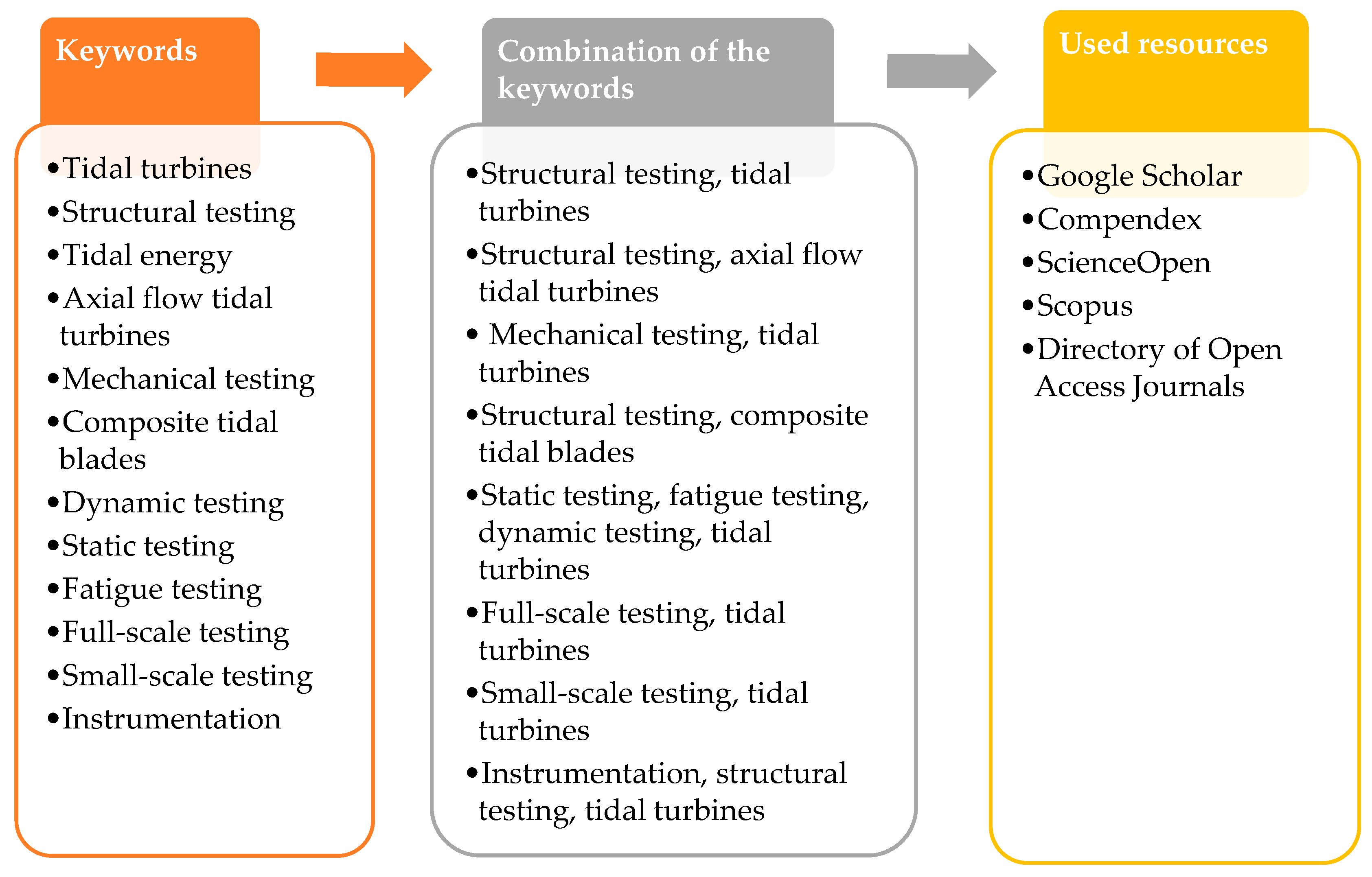
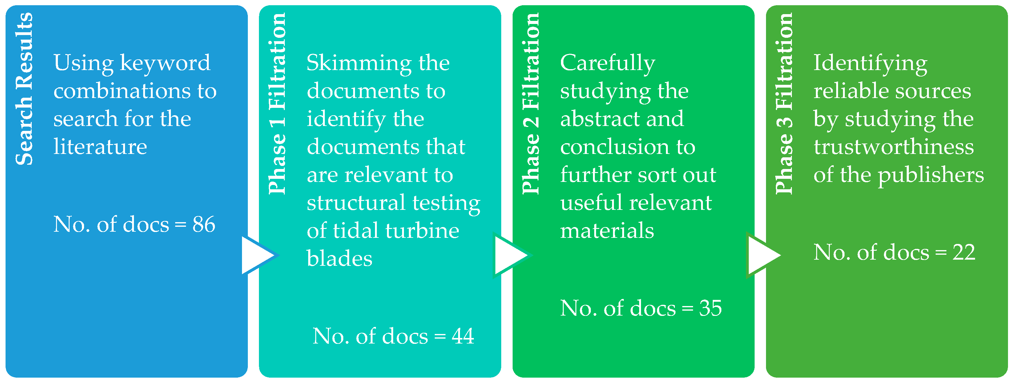
2.2. Review Methodology
3. Structural Testing Procedure
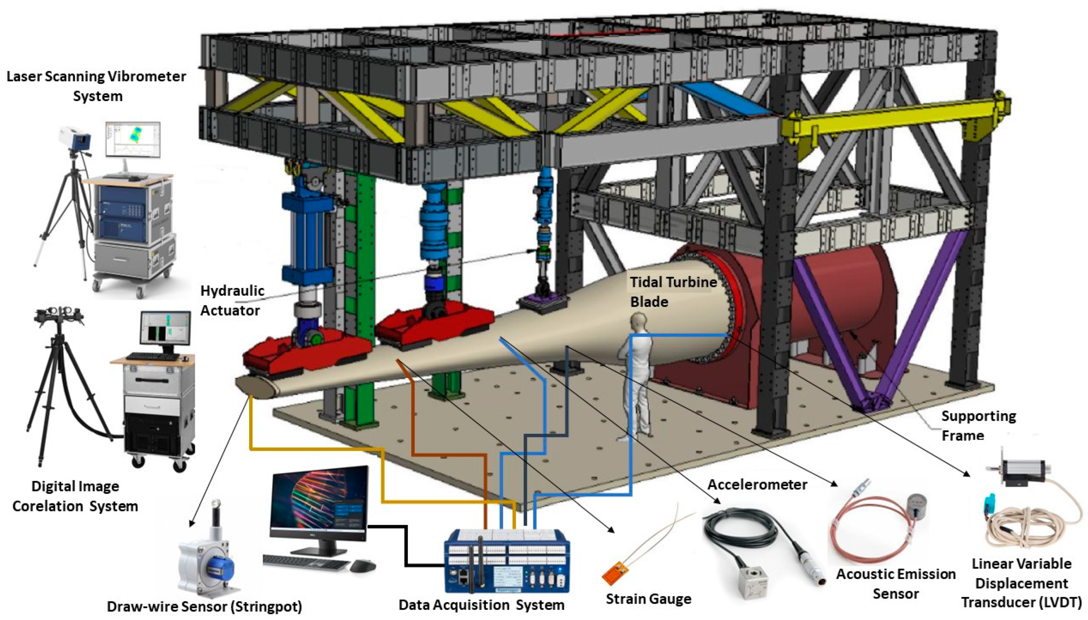
3.1. Blade Set-Up and Installation

| Equipment/Transducer | Working Principles |
|---|---|
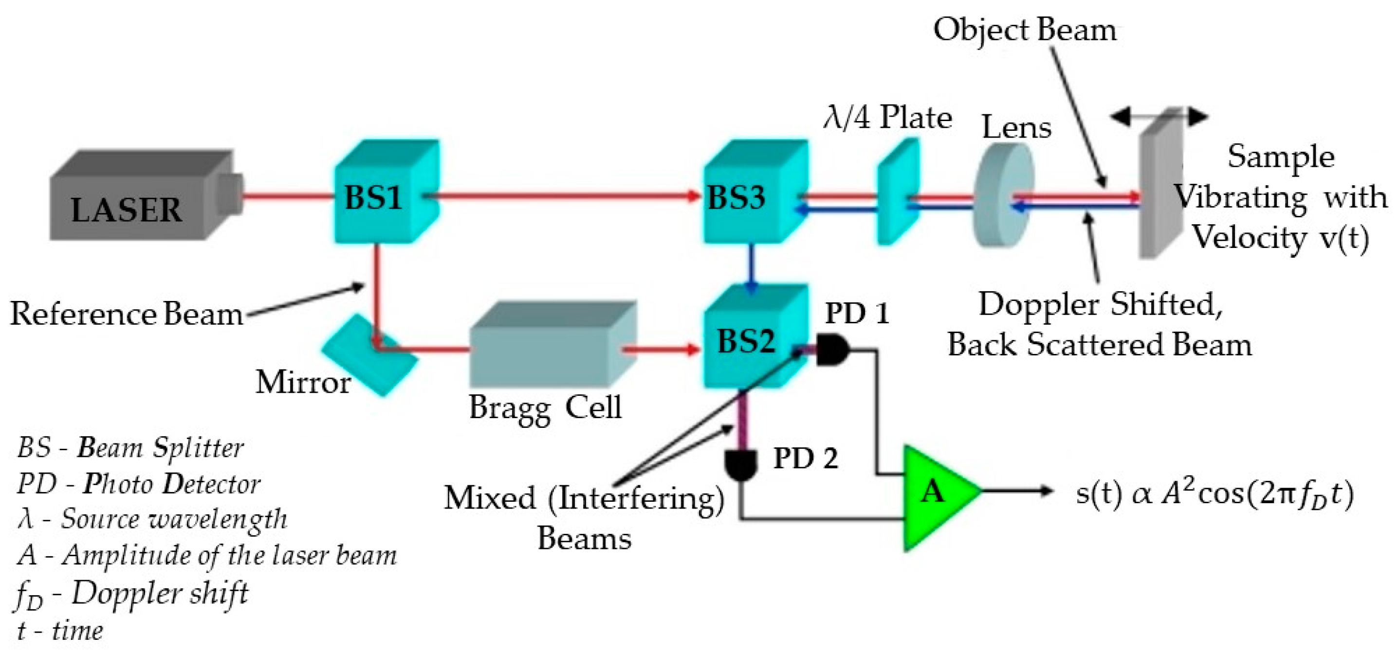
| LSV System | This noncontact velocity transducer system works based on the Doppler effect. The system measures the frequency shift of the laser-scattered beam from the vibrating surface relating to the reference beam, as shown in Figure 7 [48]. |
| DIC System | The system compares the digital images of a part or a test piece at different stages of deformation and compares these images to produce strain and deflection measurements. Measurements are limited to the area seen by the DIC cameras [49]. |
| Accelerometer | The piezoelectric materials in accelerometers generate electrical charge due to the change of motion or vibration. Then, they measure the variation of the electric charge generated as it is proportional to the acceleration of the object [50]. |
| Strain Gauge | The resistance of the strain gauge varies depending on the applied force to it, as a result of movement of the surface it is adhered to. Therefore, the change in electrical resistance is measured to identify the strain of the testing object [51]. |
| Draw-Wire Sensor | It uses a highly flexible steel wire to measure the linear movements of the objects. |
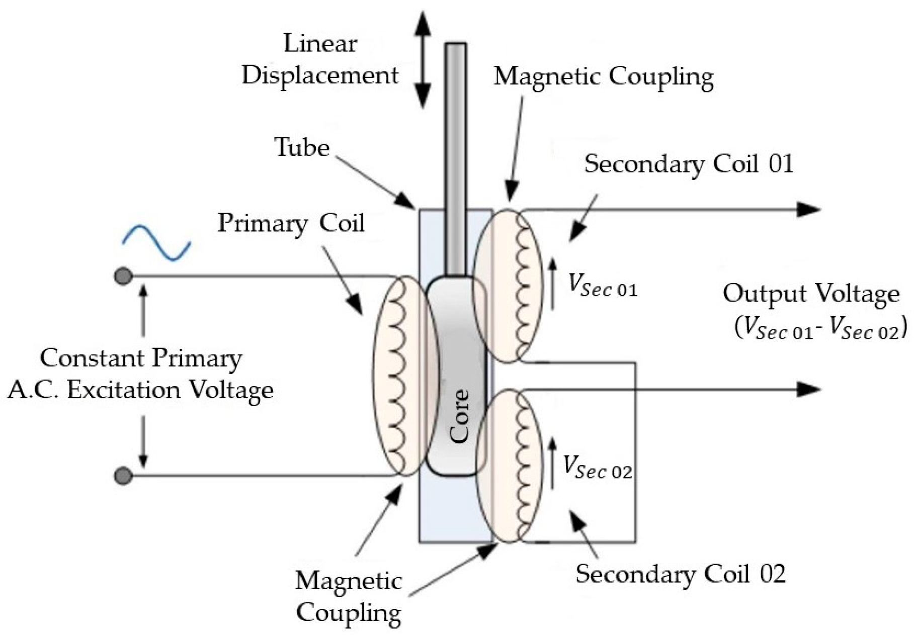
| LVDT | It measures displacement based on the mutual induction of primary and secondary windings, as represented in Figure 8. The movement of the core creates a different electromagnetic field (EMF) in both windings, and the difference is used to measure displacement [52]. |
| 3D Laser Scanner | It can be used to obtain a point cloud survey that captures the as-built geometry of the tidal blade, test fixtures and fittings, as well as full 3D geometry of the deformed blade under loading conditions. |
| Acoustic Emission Sensor | It converts high-frequency stress waves into voltage. Then, the voltages are amplified to process the acoustic emission signal data to identify defects [53]. |


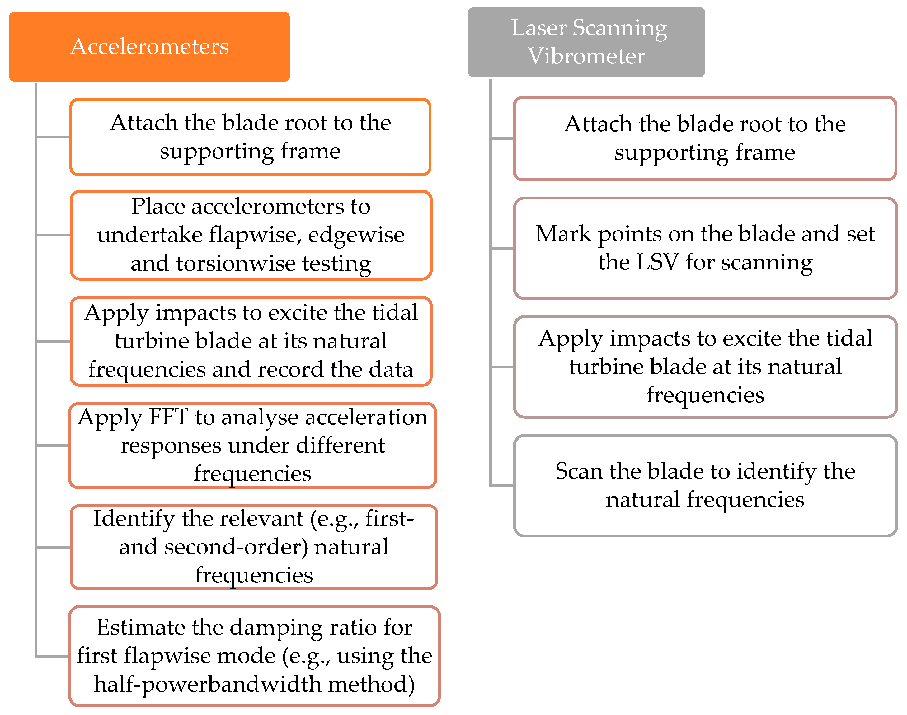
3.2. Dynamic Testing
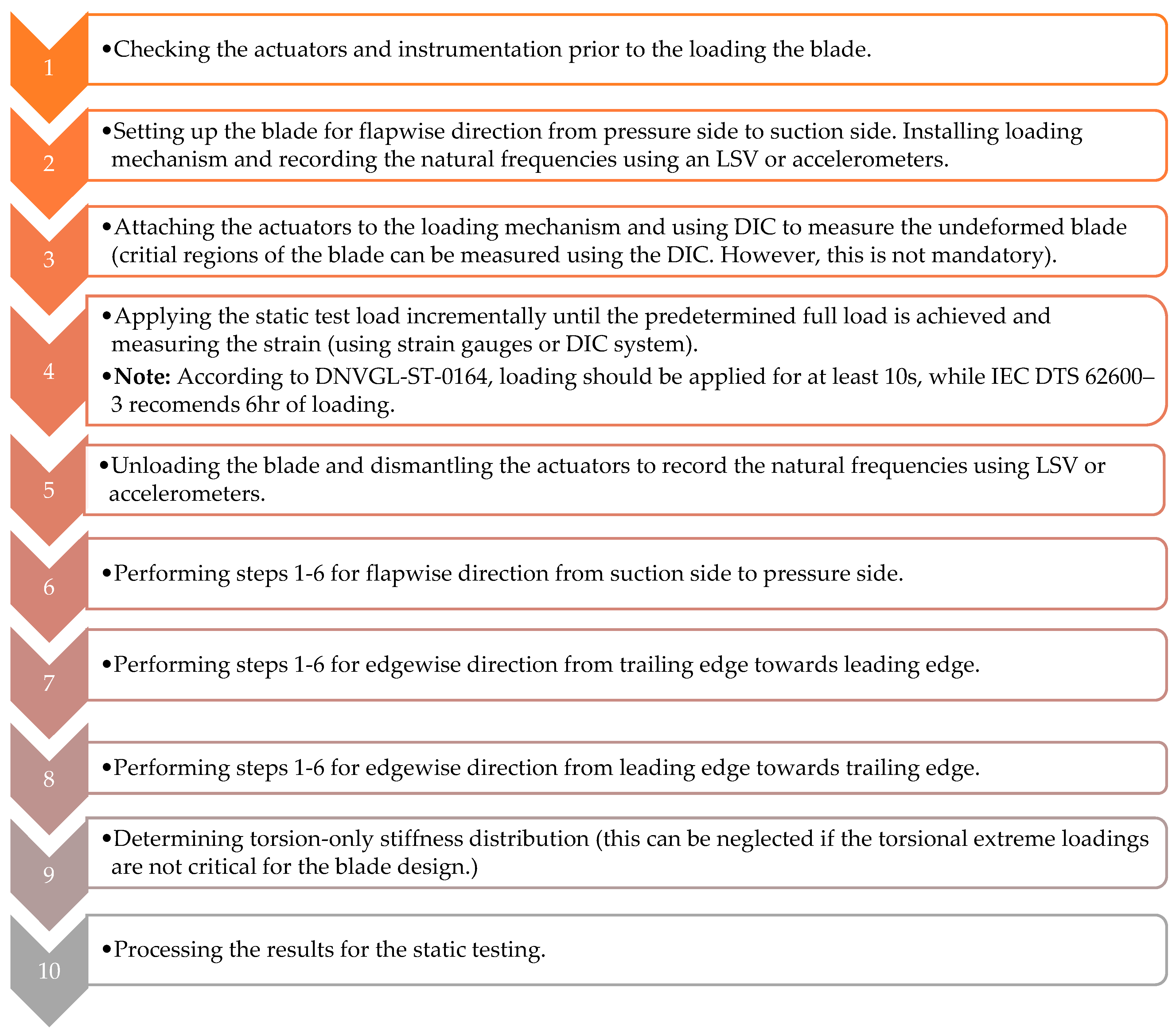
3.3. Static Testing
- Flapwise direction from pressure side to suction side;
- Flapwise direction from suction side to pressure side;
- Edgewise direction from trailing edge towards leading edge;
- Edgewise direction from leading edge towards trailing edge;
- Torsion-only stiffness distribution (this can be neglected if the torsional extreme loadings are not critical for the blade design.) [47].
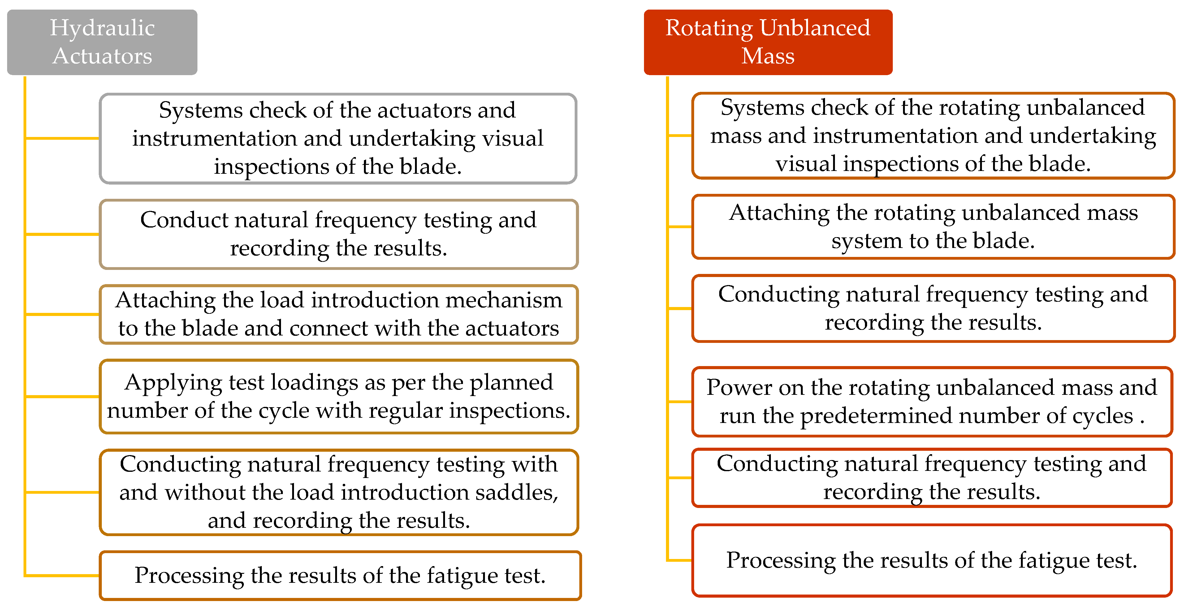
3.4. Fatigue Testing
3.5. Residual Strength Testing
4. Testing Programmes Undertaken
| No * | Specifications of the Tested Tidal Turbine Blade | University/Organization | Details of the Tests Performed | Data Acquisition and Instrumentation | Remarks |
|---|---|---|---|---|---|
| 1 | 8 m long full-scale axial flow tidal turbine blade test (1 MW tidal turbine) [11] | University of Galway (2022) Orbital Marine Power, UK EireComposites Teo, Ireland |
| 12 linear strain gauges, 18 rosette strain gauges, 7 displacement sensors, 7 accelerometers, 3 servohydraulic actuators with 5 loading points, 3 load cells, LSV and DIC systems. |
|
| 2 | 5 m long full-scale axial flow tidal turbine blade test [45] | Bureau Veritas, 1- Tech, EnerOcean, Ingeteam, Sabella, University of Edinburgh and IFREMER (2022) |
| 46 rosette strain gauges, 10 wire displacement transducers, 2 acoustic emission transducers, 2 optical fibres and a novel ultrasonic wave propagation monitoring network developed by EnerOcean, with 27 EnerOcean gages, 9 ultrasonic transducers and 2 hydraulic cylinders applying the loads through three loading points. |
|
| 3 | 3 m long full-scale axial flow tidal turbine blade test [57] | University of Galway (2021) SCHOTTEL Hydro, Germany |
| 12 linear strain gauges, 5 rosette strain gauges, 6 displacement sensors (4 LVDTs and 3 stringpots), 2 servohydraulic actuators, 2 load cells and LSV. |
|
| 4 | 3 m long small-scale hub less tidal turbine blade test (3/8 scaled 10-blade turbines with a diameter of 16 m) [62] | University of Galway (2018) OpenHydro, Ireland |
| 33 strain gauges, 8 LVDTs, 5 stringpots, 3 crack opening sensors, DIC system and 1 servohydraulic actuator. |
|
| 5 | 2.275 m long full-scale axial flow tidal turbine blade test [60] | National Renewable Energy Laboratory (NREL), (2012) |
| 29 strain gauges, 8 acoustic emission sensors, 1 servohydraulic actuator, 1 thermal imaging camera |
|
| 6 | 2 m long full-scale axial flow tidal turbine blade test [57] | University of Galway (2021) SCHOTTEL Hydro, Germany |
| 11 linear strain gauges, 4 rosette strain gauges, 7 displacement sensors (4 LVDTs and 3 stringpots), 3 accelerometers, 1 servohydraulic actuator and 1 load cell. |
|
| 7 | 1 m long small-scale axial flow tidal turbine blade test [61] | Newcastle University, UK (2021) |
| DIC system | It was focused on finding the correlation between FE model analysis and mechanical testing of the small-scaled tidal turbine blade. |
| 8 | 0.36 m long small-scale axial flow tidal turbine blade test [42] | Dalhousie University (2016) |
| 1 load cell and 1 optical displacement tracking system |
|
5. Observations from the Testing Programmes
6. Suggestions for Future Developments
- Developing a monitoring system to study the fatigue strength and residual strength of tidal turbine blades in service throughout their lifespan;
- Developing vulnerability curves to predict the remaining life of tidal turbine blades throughout their operational life;
- Identifying new testing approaches to replicate the current costly and time-consuming testing procedures more accurately and efficiently;
- Building a mechanism to distribute the predicted hydrodynamic loading across the tidal turbine blade test surface to mimic both the test shear force and bending moment distributions [11];
- A mechanism to correlate the macromechanics of composite structures and structural testing results of tidal turbine blades [61];
- Considering the harsh environmental conditions and heat-induced aging factors in seawater for structural testing [63];
- A mechanism to compare structural testing data with structural health monitoring system data to identify the gaps in laboratory testing in order to introduce safety limits for the test results;
- Developing a mechanism for repairing damaged tidal turbine blades and reinstallation for operation;
- Developing a model for selecting the most suitable internal configurations for spar caps (internal web arrangement) of tidal turbine blades and promoting the development of strong and economical tidal turbine blades.
7. Conclusions
Author Contributions
Funding
Data Availability Statement
Acknowledgments
Conflicts of Interest
Abbreviations
| DAQ | Data Acquisition |
| DIC | Digital Image Correlation |
| EMEC | European Marine Energy Centre |
| EMF | Electromagnetic Field |
| FE | Finite Element |
| FFT | Fast Fourier Transform |
| IFREMER | Institut Français de Recherche pour l’Exploitation de la Mer |
| LSV | Laser Scanning Vibrometer |
| LVDT | Linear Variable Displacement Transducer |
| NREL | National Renewable Energy Laboratory |
| TEC | Tidal Energy Converters |
References
- Lemonis, G. Wave and Tidal Energy Conversion. Encycl. Energy 2004, 7, 385–396. [Google Scholar] [CrossRef]
- Ocean Energy Europe. Ocean Energy Europe Ocean Energy Key Trends and Statistics 2021; Ocean Energy Europe: Belgium, Brussels, 2022. [Google Scholar]
- Wani, F.; Dong, J.; Polinder, H. Tidal Turbine Generators. In Advances in Modelling and Control of Wind and Hydrogenerators; IntechOpen: London, UK, 2020; Chapter 3; ISBN 978-1-83880-533-3. [Google Scholar]
- Orbital Marine Power O2-Orbital Marine. Available online: https://orbitalmarine.com/o2/# (accessed on 25 February 2023).
- Amir, G. MeyGen Sets Record with World’s First 50 GWh of Electricity Generated by Tidal Energy-Offshore Energy. Available online: https://www.offshore-energy.biz/meygen-sets-record-with-worlds-first-50gwh-of-electricity-generated-by-tidal-energy/?utm_source=marineenergy&utm_medium=email&utm_campaign=newsletter_2023-02-22 (accessed on 25 February 2023).
- SIMEC Atlantis Energy Limited SIMEC Atlantis Energy Unveils World’s Largest Single Rotor Tidal Turbine, the AR2000-SAE Renewables. Available online: https://saerenewables.com/simec-atlantis-energy-unveils-worlds-largest-single-rotor-tidal-turbine-the-ar2000/ (accessed on 25 February 2023).
- Nasab, N.M.; Kilby, J.; Bakhtiaryfard, L. The Potential for Integration of Wind and Tidal Power in New Zealand. Sustainability 2020, 12, 1807. [Google Scholar] [CrossRef]
- Walker, S.; Thies, P.R. A Review of Component and System Reliability in Tidal Turbine Deployments. Renew. Sustain. Energy Rev. 2021, 151, 111495. [Google Scholar] [CrossRef]
- Nash, S.; Phoenix, A. A Review of the Current Understanding of the Hydro-Environmental Impacts of Energy Removal by Tidal Turbines. Renew. Sustain. Energy Rev. 2017, 80, 648–662. [Google Scholar] [CrossRef]
- Ewing, F.J.; Thies, P.R.; Shek, J.; Ferreira, C.B. Probabilistic Failure Rate Model of a Tidal Turbine Pitch System. Renew Energy 2020, 160, 987–997. [Google Scholar] [CrossRef]
- Finnegan, W.; Jiang, Y.; Meier, P.; Hung, L.C.; Fagan, E.; Wallace, F.; Glennon, C.; Flanagan, M.; Flanagan, T.; Goggins, J. Numerical Modelling, Manufacture and Structural Testing of a Full-Scale 1 MW Tidal Turbine Blade. Ocean Eng. 2022, 266, 112717. [Google Scholar] [CrossRef]
- Renewable Energy from Tidal Currents; ANDRITZ HYDRO Hammerfest: Graz, Austria, 2012; pp. 6–10.
- Zhou, Z.; Scuiller, F.; Charpentier, J.-F.; Benbouzid, M.; Tang, T.; An, T.T. An Up-to-Date Review of Large Marine Tidal Current Turbine Technologies; IEEE: Piscataway, NJ, USA, 2014. [Google Scholar]
- Rajak, D.K.; Pagar, D.D.; Kumar, R.; Pruncu, C.I. Recent Progress of Reinforcement Materials: A Comprehensive Overview of Composite Materials. J. Mater. Res. Technol. 2019, 8, 6354–6374. [Google Scholar] [CrossRef]
- Hasan, M.; Zhao, J.; Jiang, Z. Micromanufacturing of Composite Materials: A Review. Int. J. Extrem. Manuf. 2019, 1, 012004. [Google Scholar] [CrossRef]
- Hsissou, R.; Seghiri, R.; Benzekri, Z.; Hilali, M.; Rafik, M.; Elharfi, A. Polymer Composite Materials: A Comprehensive Review. Compos. Struct. 2021, 262, 113640. [Google Scholar] [CrossRef]
- Davide, M.; Andreas, U.; Riccardo, M.; Joint Research Centre (European Commission). JRC Ocean Energy Status Report Technology, Market and Economic Aspects of Ocean Energy in Europe: 2016 Edition; Publications Office: Luxembourg, 2016. [Google Scholar]
- Yu, G.Q.; Ren, Y.R.; Zhang, T.T.; Xiao, W.S.; Jiang, H.Y. Hashin Failure Theory Based Damage Assessment Methodology of Composite Tidal Turbine Blades and Implications for the Blade Design. China Ocean. Eng. 2018, 32, 216–225. [Google Scholar] [CrossRef]
- Chen, L.; Lam, W.H. A Review of Survivability and Remedial Actions of Tidal Current Turbines. Renew. Sustain. Energy Rev. 2014, 43, 891–900. [Google Scholar] [CrossRef]
- Failed Tidal Turbine Explained at Symposium. Available online: https://www.cbc.ca/news/canada/nova-scotia/failed-tidal-turbine-explained-at-symposium-1.1075510 (accessed on 24 March 2023).
- Davison, A.; Mallows, T. Strangford Lough Marine Current Turbine: Environmental Statement; Royal HaskoningDHV: Amersfoort, The Netherlands, 2005. [Google Scholar]
- Savidge, G.; Ainsworth, D.; Bearhop, S.; Christen, N.; Elsaesser, B.; Fortune, F.; Inger, R.; Kennedy, R.; McRobert, A.; Plummer, K.E.; et al. Strangford Lough and the SeaGen Tidal Turbine; Springer: Berlin/Heidelberg, Germany, 2014; pp. 153–172. [Google Scholar] [CrossRef]
- Scotrenewables Tidal Power Ltd. SR250 Deployment Fall of Warness: Environmental Statement Volume I-Environmental Statement. Available online: https://tethys.pnnl.gov/publications/scotrenewables-tidal-power-ltd-sr250-deployment-fall-warness-environmental-statement-0 (accessed on 6 February 2023).
- Liu, X.; Feng, B.; Liu, D.; Wang, Y.; Zhao, H.; Si, Y.; Zhang, D.; Qian, P. Study on Two-Rotor Interaction of Counter-Rotating Horizontal Axis Tidal Turbine. Energy 2022, 241, 122839. [Google Scholar] [CrossRef]
- Qian, P.; Feng, B.; Liu, H.; Tian, X.; Si, Y.; Zhang, D. Review on Configuration and Control Methods of Tidal Current Turbines. Renew. Sustain. Energy Rev. 2019, 108, 125–139. [Google Scholar] [CrossRef]
- Voith HyTide at EMEC. Available online: https://tethys.pnnl.gov/project-sites/voith-hytide-emec (accessed on 20 February 2023).
- Gaamouche, R.; Redouane, A.; El Hasnaoui, A.; Belhorma, B.; Kchikach, M.; Jeffali, F. Review of Technologies and Direct Drive Generator Systems for a Grid Connected Marines Current Turbine. J. Mater. Environ. Sci. 2018, 9, 2631–2644. [Google Scholar]
- Paboeuf, S.; Sun, P.Y.K.; Macadré, L.M.; Malgorn, G. Power Performance Assessment of the Tidal Turbine Sabella D10 Following IEC62600-200. In Proceedings of the International Conference on Offshore Mechanics and Arctic Engineering-OMAE; American Society of Mechanical Engineers: New York, NY, USA, 2016; Volume 6. [Google Scholar] [CrossRef]
- Zainol, M.Z.; Zainol, I. A Review on the Status of Tidal Energy Technology Worldwide; Science International: Lahore, Pakistan, 2017. [Google Scholar]
- Nova Innovation-Shetland Tidal Array. Available online: https://tethys.pnnl.gov/project-sites/nova-innovation-shetland-tidal-array (accessed on 24 February 2023).
- European Case Study-Shetland Tidal Array. Available online: https://www.novainnovation.com/markets/scotland-shetland-tidal-array/ (accessed on 24 February 2023).
- Ocean Energy Europe. Ocean Energy Project Spotlight Investing in Tidal and Wave Energy; Ocean Energy Europe: Belgium, Brussels, 2017. [Google Scholar]
- Paimpol-Brehat Tidal Farm. Available online: https://www.power-technology.com/projects/paimpol-brehat-tidal-farm/ (accessed on 15 February 2023).
- World’s Largest 5-Turbine Tidal Array Installed in The Netherlands. Available online: https://maritimecyprus.com/2015/10/16/worlds-largest-5-turbine-tidal-array-installed-in-the-netherlands/ (accessed on 26 January 2023).
- MeyGen Update–AR1500 Turbine Deployed in Record Time-SAE Renewables. Available online: https://saerenewables.com/2225/ (accessed on 7 February 2023).
- Rajgor, G. Tidal Developments Power Forward. Renew. Energy Focus 2016, 17, 147–149. [Google Scholar] [CrossRef]
- Wani, F.; Polinder, H. A Review of Tidal Current Turbine Technology: Present and Future. In Proceedings of the 12th European Wave and Tidal Energy Conference, Cork, Ireland, 27 August–1 September 2020. [Google Scholar]
- Scotrenewables SR 2000 Floating Tidal Turbine. Available online: https://www.weamec.fr/en/synthesis/scotrenewables-sr-2000-floating-tidal-turbine/ (accessed on 7 February 2023).
- Díaz-Dorado, E.; Carrillo, C.; Cidras, J.; Román, D.; Grande, J. Performance Evaluation and Modelling of the Atir Marine Current Turbine. IET Renew. Power Gener. 2021, 15, 821–838. [Google Scholar] [CrossRef]
- Edward, M.F.; Finlay, W.; Yadong, J.; Afrooz, K.; Jamie, G. Design and Testing of a Full-Scale 2 MW Tidal Turbine Blade. In Proceedings of the 13th European Wave and Tidal Energy Conference, Naples, Italy, 1–6 September 2019. [Google Scholar]
- Senavirathna, G.R.U.; Galappaththi, U.I.K.; Ranjan, M.T.T. A Review of End-Life Management Options for Marine Structures: State of the Art, Industrial Voids, Research Gaps and Strategies for Sustainability. Clean. Eng. Technol. 2022, 8, 100489. [Google Scholar] [CrossRef]
- Murray, R. Passively Adaptive Tidal Turbine Blades: Design Methodology and Experimental Testing; Elsevier: Amsterdam, The Netherlands, 2016. [Google Scholar]
- FastBlade-World’s First Regenerative Fatigue Test Facility. Available online: https://www.fastblade.eng.ed.ac.uk/ (accessed on 7 March 2023).
- Test and Demonstration Facilities for Wind Energy Needed to Promote a Competitive Wind Industry in Denmark; MEGAVIND: Langebrogade, Denmark, 2016.
- Davies, P.; Dumergue, N.; Arhant, M.; Nicolas, E.; Paboeuf, S.; Mayorga, P. Material and Structural Testing to Improve Composite Tidal Turbine Blade Reliability. Int. Mar. Energy J. 2022, 5, 57–65. [Google Scholar] [CrossRef]
- IEC DTS 62600–3; Marine Energy-Wave, Tidal and Other Water Current Converters-Part 3: Measurement of Mechanical Loads. International Electrotechnical Commission: Geneva, Switzerland, 2019.
- DNVGL-ST-0164; Tidal Turbines. Det Norske Veritas Germanischer Lloyd: Oslo, Norway, 2015.
- Zipser, L.; Franke, H. Laser-Scanning Vibrometry for Ultrasonic Transducer Development. Sens. Actuators A Phys. 2004, 110, 264–268. [Google Scholar] [CrossRef]
- McCormick, N.; Lord, J. Digital Image Correlation for Structural Measurements. Proc. Inst. Civ. Eng.-Civ. Eng. 2012, 165, 185–190. [Google Scholar] [CrossRef]
- Niu, W.; Fang, L.; Xu, L.; Li, X.; Huo, R.; Guo, D.; Qi, Z.; Niu, W.; Fang, L.; Xu, L.; et al. Summary of Research Status and Application of MEMS Accelerometers. J. Comput. Commun. 2018, 6, 215–221. [Google Scholar] [CrossRef]
- Tutak, P. Application of Strain Gauges in Measurements of Strain Distribution in Complex Objects. JACSM 2014, 6, 135. [Google Scholar] [CrossRef]
- Qian, Z.; Fan, Y.; Lu, Z. Application of Draw-Wire Displacement Sensors on Structural Health Monitoring of Jiangyin Bridge. In Proceedings of the Nondestructive Evaluation and Health Monitoring of Aerospace Materials, Composites, and Civil Infrastructure V, San Diego, CA, USA, 20 March 2006; Volume 6176. [Google Scholar]
- He, Y.; Li, M.; Meng, Z.; Chen, S.; Huang, S.; Hu, Y.; Zou, X. An Overview of Acoustic Emission Inspection and Monitoring Technology in the Key Components of Renewable Energy Systems. Mech. Syst. Signal Process. 2021, 148, 107146. [Google Scholar] [CrossRef]
- Manfred, S.; Matija, S.; Renzo, S. Handbook of the Use of Lasers in Conservation and Conservation Science; COST Office: Brussels, Belgium, 2008; Chapter 3; ISBN 9738810930. [Google Scholar]
- Linear Variable Differential Transformer or LVDT. Available online: https://www.electronics-tutorials.ws/io/linear-variable-differential-transformer.html (accessed on 7 December 2022).
- Jiang, Y.; Finnegan, W.; Vanhari, A.K.; Meier, P.; Fagan, E.; Goggins, J. Natural Frequency Measurement of a 13-M Wind Turbine Blade Using Different Techniques. In Proceedings of the Civil Engineering Research in Ireland, Cork, Ireland, 27–28 August 2020; pp. 265–270. [Google Scholar]
- Glennon, C.; Finnegan, W.; Kaufmann, N.; Meier, P.; Jiang, Y.; Starzmann, R.; Goggins, J. Tidal Stream to Mainstream: Mechanical Testing of Composite Tidal Stream Blades to de-Risk Operational Design Life. J. Ocean Eng. Mar. Energy 2022, 8, 163–182. [Google Scholar] [CrossRef]
- Seablade-ÉireComposites. Available online: https://www.eirecomposites.com/seablade/ (accessed on 7 January 2023).
- Meier, P.; Finnegan, W.; Cronin, P.; Donegan, J.; Barrington, M.; Hung, L.C. Jamie Goggins Static and Fatigue Testing of a Full Scale Helical River Turbine. In Proceedings of the Civil Engineering Research in Ireland, Cork, Ireland, 27–28 August 2020. [Google Scholar]
- Verdant Composite Prototype Blade Fatigue Test Report; National Renewable Energy Laboratory: Golden, CO, USA, 2012.
- Gonabadi, H.; Oila, A.; Yadav, A.; Bull, S. Structural Performance of Composite Tidal Turbine Blades. Compos. Struct. 2021, 278, 114679. [Google Scholar] [CrossRef]
- de la Torre, O.; Moore, D.; Gavigan, D.; Goggins, J. Accelerated Life Testing Study of a Novel Tidal Turbine Blade Attachment. Int. J. Fatigue 2018, 114, 226–237. [Google Scholar] [CrossRef]
- Jiang, Y.; Finnegan, W.; Wallace, F.; Flanagan, M.; Flanagan, T.; Goggins, J. Structural Analysis of a Fibre-Reinforced Composite Blade for a 1 MW Tidal Turbine Rotor under Degradation of Seawater. J. Ocean Eng. Mar. Energy 2023, 10, 1–18. [Google Scholar] [CrossRef]


| No | Year | Project Name | Location | Number of Rotors | Number of Blades per Rotor | Rotor Diameter (m) | Capacity per Rotor (kW) | Remarks |
|---|---|---|---|---|---|---|---|---|
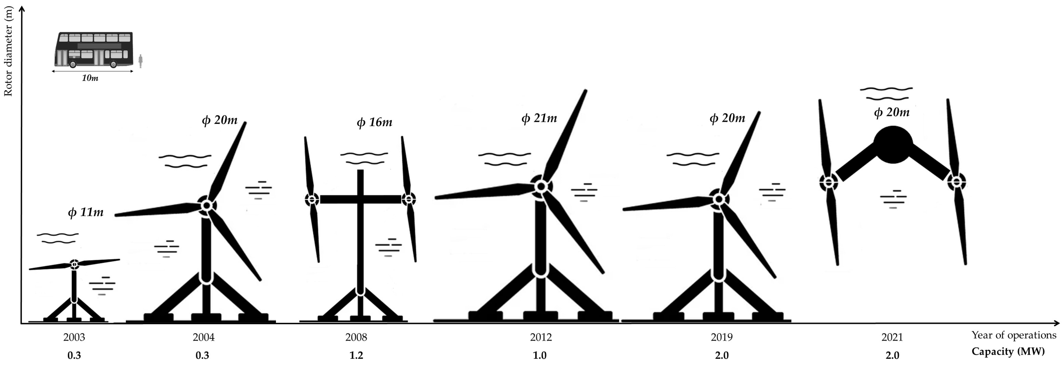
| 1 | 2003 | Seaflow | Lynmouth in Devon | 1 | 2 | 11.00 | 300 | The world’s first “full-size” tidal turbine. The turbine is installed to a structure fixed to the seabed [21] |
| 2 | 2004 | HS300 | Kvalsund, Finnmark, Norway | 1 | 3 | 20.00 | 300 | A tidal prototype connected to the grid for the first time in the world. The turbine is fixed to the seabed [12,13] |
| 3 | 2008 | SeaGen | Strangford Narrows in Northern Ireland | 2 | 2 | 16.00 | 600 | A system to generate 1.2 MW of rated power. The turbines are attached to a structure fixed to the seabed (the world’s first commercial-scale tidal energy project) [22] |
| 4 | 2011 | SR250 | European Marine Energy Centre (EMEC) tidal test site in the Fall of Warness | 2 | 2 | 8.00 | 125 | A system to generate 250 kW of rated power (the SR250 has become the world’s first floating tidal turbine) [23] |
| 5 | 2011 | AK-1000 | European Marine Energy Centre (EMEC) tidal test site in the Fall of Warness | 2 | 3 | 18.00 | 500 | The tidal turbines are attached to the same hub connection, which is fixed to the seabed and generates 1 MW rated power [24] |
| 6 | 2011 | AR1000 | European Marine Energy Centre (EMEC) tidal test site in the Fall of Warness | 1 | 3 | 18.00 | 1000 | The turbine is fixed to the seabed [25] |
| 7 | 2012 | HS1000 | European Marine Energy Centre (EMEC) tidal test site in the Fall of Warness | 1 | 3 | 21.00 | 1000 | The turbine is fixed to the seabed [12,13] |
| 8 | 2013 | HyTide 1000 | European Marine Energy Centre (EMEC) tidal test site in the Fall of Warness | 1 | 3 | 13.00 | 1000 | The turbine is fixed to the seabed [13,26,27] |
| 9 | 2015 | Sabella | Ushant island, Brittany (France) | 1 | 6 | 10.00 | 1000 | The turbine is attached to the seabed using a four-leg structure [13,27,28] |
| 10 | 2015 | Delta Stream | Placed on the seabed in Ramsey Sound off the Pembrokeshire coast | 3 | 3 | 15.00 | 400 | A tidal turbine system attached to a triangular steel base placed on the seabed to generate 1.2 MW rated power [29] |
| 11 | 2016 | Nova M100 | Bluemull Sound, Shetland, off the far-northeast coast of mainland UK | 6 | 2 | 8.50 | 100 | The world’s first offshore tidal array to generate rated capacity of 300 kW. Another three rotors were added at later stages. The turbines are fixed to the seabed [30,31] |
| 12 | 2016 | OpenHydro Turbines | Paimpol Bréhat, Brittany (France) | 2 | 10 | 16.00 | 500 | Each turbine is installed to a two-column structure fixed to the seabed. Has 1.0 MW of rated power [32,33] |
| 13 | 2016 | Tocardo T-2 Tidal Turbines | Eastern Scheldt barrier, Zeeland (The Netherlands) | 5 | 2 | 5.50 | 240 | Turbines are attached to a single structure to form the world’s largest commercial tidal array. System has 1.2 MW of rated power [32,34] |
| 14 | 2016 | AR1500 | Site in Pentland Firth, Scotland | 1 | 3 | 18.00 | 1500 | An active-pitch, full-yawing tidal turbine system fixed to the seabed [35,36,37] |
| 15 | 2016 | SR2000 | Orkney Islands, Scotland | 2 | 2 | 16.00 | 1000 | A floating tidal turbine system with 2 MW of rated power [38] |
| 16 | 2018 | Atir marine current turbine | Ria of Vigo (Northwest of Spain) | 2 | 3 | 19.00 | 750 | The tidal turbines are attached to the same hub connection and generate 1.5 MW of rated power. It is a floating system [39] |
| 17 | 2019 | OpenHydro Turbines | Naru Strait (Japan) | 1 | 10 | 16.00 | 2000 | Turbine is installed to a two-column structure fixed to the seabed [32] |
| 18 | 2019 | AR2000 | Scotland | 1 | 3 | 20.00 | 2000 | An active-pitch, full-yawing turbine attached to seabed [6,7] |
| 19 | 2021 | Orbital O2 | Orkney Islands, Scotland | 2 | 2 | 20.00 | 1000 | 2.0 MW of rated power floating tidal turbine system [40] |
| Publication Details | Finding | Remarks |
|---|---|---|
| [11,45,61,62] | Validated the FE model results with the structural testing. | Tidal energy developers will be able to conduct comprehensive FE analysis and ensure the structural integrity of tidal turbine blades in the future (with the support of further validation programs). |
| [45] | The internal damage mechanism of the blade was established by analysing the cut sections of the blade. | Manufacturers will be able to minimize the internal damage of the tidal turbine blades in the future. |
| [11] | It is not necessary to statically load the blades for 6 h during the static test program, as this does not affect the static test results. | The 6 h loading requirement of the IEC DTS 626003 standards can be neglected. Holding the load for a duration of 30 s during static testing should suffice. |
| [62] | Demonstration of a unique approach to testing new-generation TECs with different designs. | The research methodology used for novel hubless tidal turbine blades is crucial for conducting structural tests for novel TEC designs in the future. |
| [57] | A linear relationship between static loading and tip deflection of the tidal turbine blades. | Based on this research observation, the designers can roughly estimate the deflections of the tidal turbine blades at the design stage. However, the tip deflection depends on several factors, including the environmental conditions, material properties of the turbine, structural design and geometrical parameters of the turbine. |
| [61] | Conducted composite material testing, FE analysis and small-scale structural testing to assess industrial-level tidal turbine blades. | It demonstrates the possibility of undertaking structural testing for small-scale tidal turbine blades to predict the performance of full-scale blades. However, there are constraints to be considered. |
| [42] | Performed static tests on damaged and repaired tidal turbine blades and found that the deflection responses of the damaged and repaired blades were less than 1.2% for a 25 N static load. | This approach will be important for the future development of the tidal energy sector, as it needs to focus on the damage repair strategies of tidal turbine blades to achieve sustainability goals. However, the result of this exercise is highly dependent on the location, size and repair strategy of the damage. Therefore, a more detailed research study is necessary to validate the reliability of repaired blades to be reused in tidal power generation. |
Disclaimer/Publisher’s Note: The statements, opinions and data contained in all publications are solely those of the individual author(s) and contributor(s) and not of MDPI and/or the editor(s). MDPI and/or the editor(s) disclaim responsibility for any injury to people or property resulting from any ideas, methods, instructions or products referred to in the content. |
© 2023 by the authors. Licensee MDPI, Basel, Switzerland. This article is an open access article distributed under the terms and conditions of the Creative Commons Attribution (CC BY) license (https://creativecommons.org/licenses/by/4.0/).
Share and Cite
Munaweera Thanthirige, T.R.; Goggins, J.; Flanagan, M.; Finnegan, W. A State-of-the-Art Review of Structural Testing of Tidal Turbine Blades. Energies 2023, 16, 4061. https://doi.org/10.3390/en16104061
Munaweera Thanthirige TR, Goggins J, Flanagan M, Finnegan W. A State-of-the-Art Review of Structural Testing of Tidal Turbine Blades. Energies. 2023; 16(10):4061. https://doi.org/10.3390/en16104061
Chicago/Turabian StyleMunaweera Thanthirige, Tenis Ranjan, Jamie Goggins, Michael Flanagan, and William Finnegan. 2023. "A State-of-the-Art Review of Structural Testing of Tidal Turbine Blades" Energies 16, no. 10: 4061. https://doi.org/10.3390/en16104061