Article

Active Air-Source Heat Storage and Release System for Solar Greenhouses: Design and Performance

1
College of Horticulture, North West Agriculture and Forestry University, Xianyang 712100, China
2
State Grid Shaanxi Electric Power Research Institute, Xi’an 710199, China
3
Key Laboratory of Horticultural Engineering in Northwest Facilities, Ministry of Agriculture, Xianyang 712100, China
4
Facility Agriculture Engineering Technology Research Center of Shaanxi Province, Xianyang 712100, China
*
Author to whom correspondence should be addressed.
Energies 2023, 16(1), 89; https://doi.org/10.3390/en16010089
Submission received: 27 November 2022 / Revised: 18 December 2022 / Accepted: 19 December 2022 / Published: 21 December 2022

Abstract

:
The temperature difference between day and night in a solar greenhouse is large. Heat in a greenhouse is typically in excess during the day while the temperature is low and the humidity is high at night. This study designs and tests an active heat storage and release air-source heat-pump system with a thermally insulated water tank as the energy storage body. By comparing air temperature and humidity in a test greenhouse with a control greenhouse in typical weather conditions, the power consumption and performance of the system are evaluated. The results show that compared with the control greenhouse, the average daytime temperature of the test greenhouse is lowered by about 3 °C during the operation of the system in typical weather conditions. At night, the average temperature is increased by about 4 °C, and the relative humidity is decreased by about 20%. When optimized, the maximum coefficient of performance (COP) of the system can reach 4.32 in heat storage mode. The nighttime heat release from the energy storage tank accounts for 26.9% to 51.2% of the nighttime energy consumption, and the energy utilization efficiency is 59.6% to 497.0%. This study provides a new way to control environmental parameters in solar greenhouses.

1. Introduction

With the proposal of the “double carbon” goal, the concept of green development has become very topical. Among the many possible kinds of carbon sequestration measures, carbon dioxide absorption by plants through photosynthesis is an effective way to achieve carbon sequestration when used in biofuel schemes, for example. In many regions, due to the limitation of the temperature environment, plants cannot grow all year round. Greenhouse facilities have effectively solved this problem by protecting counter-season plants from extreme cold or heat [1]. Efficient environmental control and “clean” heating are essential for greenhouse systems attempting to reduce carbon emissions.
In the research on the application of clean energy, the utilization of solar energy is mainly studied. Rui et al. [2] improved the utilization of solar energy by optimizing the photovoltaic installation scheme. Sommer et al. [3] combined the porous method with a type of “active insulation” that uses the power of solar radiation to heat the walls on the façade, reducing heat loss by raising the internal surface temperature, as well as improving energy efficiency and reducing carbon emissions. Research on the efficient use of air is also increasing year by year. Air-source heat-pump (ASHP) technology has higher efficiency than direct electric heating [4] because it uses air as a heat source, and has lower use and installation costs [5,6], and it has been widely used in Europe, Australia, and other regions [7]. Keeping the annual growth rate of the new heat pump unit at a high enough level is still the world’s main challenges [8]. At present, there are three main key areas of air-source heat pump research: defrosting management, ASHP system management, and ASHPs as smart grid demand response components [9,10,11,12,13]. For example, Runan et al. [14] conducted an experimental study on improving the performance of ASHP heating, analyzed the advantages and disadvantages of the system and its influence on heating performance, and put forward measures to further improve the performance of ASHP heating, but did not analyze the feasibility of its application in the field of agriculture. Xiaohui et al. [15] discussed the application of low-temperature ASHP technology and proved that it has great potential, but they did not carry out experimental analysis for the unique heating characteristics of greenhouses. Youssef et al. [16] added heat exchange tubes with phase change materials to a solar heat pump system and found that the coefficient of performance (COP) of the combined heating system improved significantly, but they did not consider active heat storage and release.
In general, at present, ASHP technology has been mainly applied to industrial buildings and human habitation and is also used in many large pieces of dehumidification and heating equipment [17,18], but applications in greenhouses have been limited. In Europe, ASHP applications are more focused on consumer-based field trials [19,20,21,22]. In recent years, there has been more research on upgrading the ASHP system by Chinese researchers. In general, at present, ASHP technology has been mainly applied to industrial buildings and human habitation, and applications in greenhouses have been limited. Hailin [23] studied the performance of series and parallel solar ASHP systems and proved that they have good operational effects. Yan [24] conducted experimental and simulation research on solar-assisted ASHP heating and found that solar energy equipment can significantly improve the efficiency of an ASHP system. Qianru et al. [25] analyzed a solar-ASHP composite heating system in the plateau cold-region of China and proved that a composite system could maintain a high COP in the cold season. Rongjiang et al. showed that when different personnel control modes were considered, low-temperature AAHPs could meet the requirements for comfortable living and had a great potential to reduce heating energy consumption [26].
All the above studies have confirmed the performance stability of ASHP, but less consideration has been given to the application of ASHP systems in agricultural greenhouses. Bing et al. [27] conducted an experimental study on the operation and performance of solar energy combined with an ASHP heating system in greenhouses in Kunming, China. The results showed that the heating delivered by the system was stable and could effectively meet the growth demand of the associated crops. The COP of the system was shown to be up to 3.94. Xianpeng et al. [28,29] and Yuxin et al. [30] also examined solar energy combined with an ASHP system in greenhouses and showed that the system could achieve reductions in energy consumption. However, to date, there has been no research on the optimization and improvement of an ASHP system from the perspective of active heat storage and release, and hence, the systems currently lack autonomous performance regulation.
In this paper, an ASHP system with an active heat storage and release function is investigated. Through a specially designed energy storage tank, excess heat energy obtained during the day can be stored and released to avoid low temperatures at night, effectively balancing the internal heat demand of a greenhouse. This system not only provides a new way to regulate the environmental parameters of solar greenhouses, but also provides a reference for the modernization of greenhouse agricultural systems.

2. ASHP System Design and Test
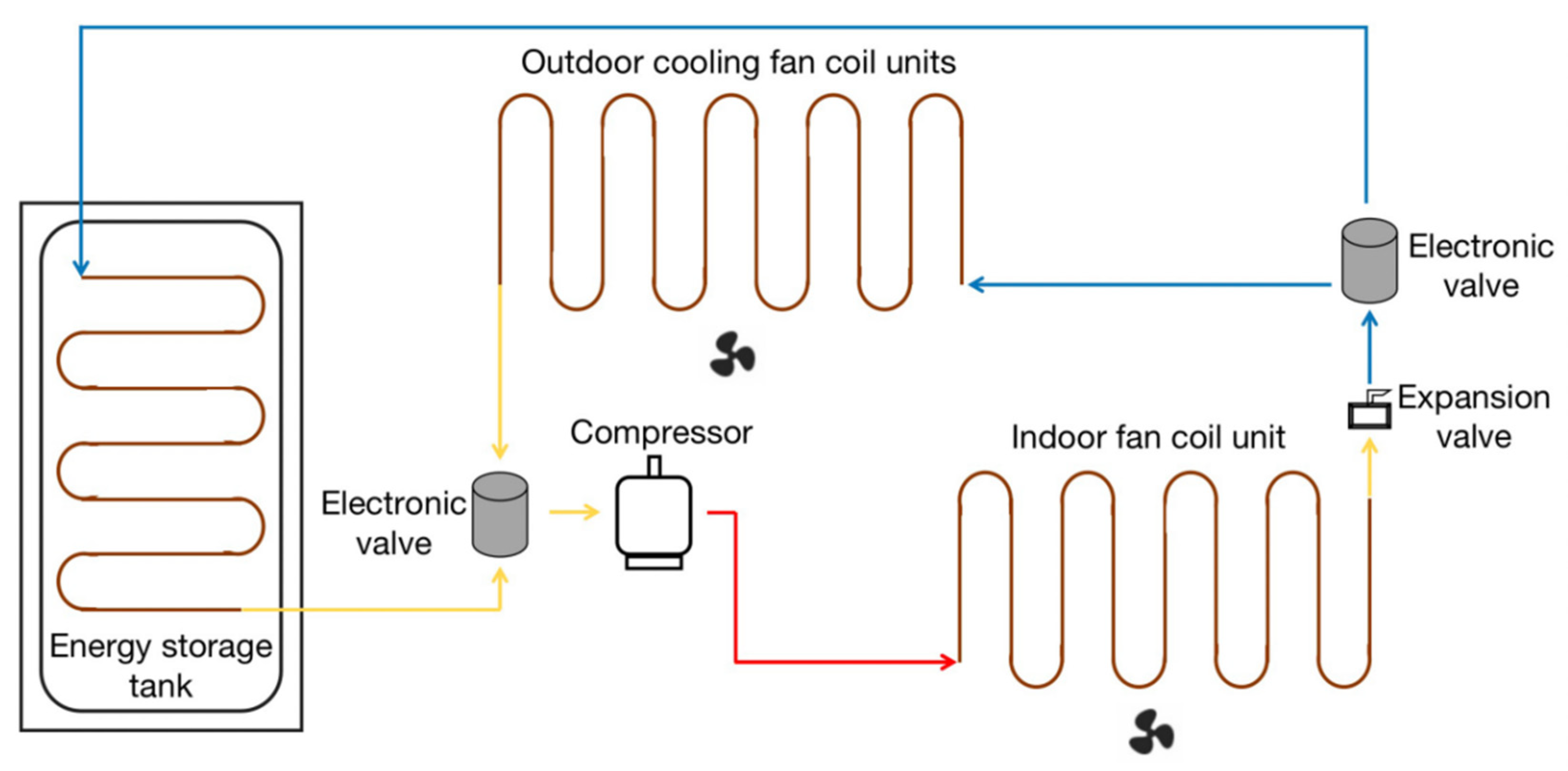
2.1. System Design

The active heat storage and release ASHP system designed in this paper is essentially a heat pump unit with a compression heat pump as the core of the system. The system is composed of an external outdoor unit, an internal indoor unit, and an energy storage tank (Figure 1). The specific parameters of the active heat storage and release ASHP system are shown in Table 1.
A compressor, solenoid directional valve and outdoor cooling fan coil units are integrated in the external unit. The solenoid directional valve controls four heating and cooling (heat storage) circuits connected to the external unit and the energy storage tank. The whole system can automatically start and stop operation according to a preset control strategy and has the capacity of heating and cooling (heat storage). The difference between an active heat storage and release ASHP system based on a compression heat pump as opposed to a conventional heat pump is that there are two additional heating and cooling loops on the electromagnetic directional valve of the system. These can be connected to the indoor condenser and the energy storage tank.
The energy storage body is an energy storage tank with a capacity of 500 L water (Figure 1b). The outer wall of the tank is equipped with a thermal insulation layer, and an annular heat exchange coil is arranged inside the tank.
The internal indoor unit (Figure 1b) consists of a fan and indoor fan coil unit with a rated input power of 0.8 kW. When the unit is running, it can not only be used as the terminal control system to regulate the temperature in the greenhouse, but also as the heat recovery system to transfer the excess heat in the greenhouse into the energy storage tank, so as to realize “peak cutting and valley filling” of the greenhouse environmental temperature.
The schematic structure of the active heat storage and release ASHP system is shown in Figure 2. A refrigerant working medium evaporates to absorb heat into the low-temperature and low-pressure gas. The gas is then compressed by the compressor into a high-temperature and high-pressure gas which enters the condenser to exchange heat with air inside the greenhouse. After the resulting heat release, the working medium reverts back to a low-temperature and low-pressure liquid and returns to the evaporator, where it enters the next cycle.

2.2. Operational Modes

The active heat storage and release ASHP system has three operational modes: cooling (with active heat storage) mode; heating (with active heat storage and release) mode; and active heating mode. The specific working mode can be selected in real time according to the weather conditions and indoor and outdoor temperatures. The target temperature range is generally set according to the temperature requirements of the greenhouse crop. The specifics of each operational mode are as follows:
Cooling (with active heat storage) mode: When the temperature in the greenhouse exceeds a set starting temperature (25 °C), the system starts a cooling mode. The indoor fan cools the greenhouse, and the heat collection system stores the excess heat from the greenhouse in the energy storage tank. When the temperature in the greenhouse is lower than a set minimum temperature (15 °C), the system stops running.
Heating (with active heat storage and release) mode: When the temperature in the greenhouse is higher than a certain temperature (25 °C), the system starts a refrigeration (heat storage) mode and collects the excess heat from the greenhouse. When the temperature in the greenhouse at night and in the early morning is lower than a set minimum temperature (10 °C), heat is released from the energy storage tank back into the greenhouse. If the release of stored heat does not increase the temperature above the set temperature (10 °C), the outdoor unit starts to absorb heat from the external air and the system releases it into the greenhouse.
Active heating mode: When the temperature in the greenhouse is lower than a set minimum temperature (10 °C), the external unit of the heat pump system is activated, heat is extracted from the external air, and the indoor unit delivers the heat into the greenhouse. In this mode, the energy storage tank does not store heat.

2.3. System Tests

2.3.1. Experimental Greenhouse

The system was tested in an east–west orientated solar greenhouse constructed from a large arch shed in the Yangling District, Shaanxi province, China. A schematic diagram of its structure and the layout of internal and external measuring points are shown in Figure 3. The total length of the greenhouse was 29 m, the span was 9.2 m, the ridge height was 3.8 m, and the rear wall was 3.6 m high. The front roof consisted of a single-layer film structure with a thermal insulation system that could be automatically rolled out. The inner surface of the gable was covered with a thermal insulation board, the back wall was made from cement-lined bricks, and the whole greenhouse had good thermal insulation performance.
The whole greenhouse space was divided into three compartments along its length by heat insulation panels. Each compartment was connected by a door made from a double-layer wind-insulation curtain. The indoor area of each compartment was about 90 m2, and the volume of each space was about 280 m3. In each compartment, except for hardening treatment adjacent to the rear wall, the ground surface consisted of soil.
An active heat storage and release ASHP system was installed through the east gable side of the compartment at that end of the experimental greenhouse. This compartment is termed Test Greenhouse (TG). No active temperature control measures were applied to the compartment adjacent to the gable on the west side of the experimental greenhouse. This compartment is termed the Control Greenhouse (CG). The measuring equipment is arranged in the same position in both compartments (Figure 3).

2.3.2. Data Collection

A temperature and humidity sensor was arranged in the center of the two compartmental greenhouses, 1 m from the ground, at point C (Figure 3). Thermocouple temperature sensors were placed in the center of the energy storage water tank. Data from these sensors were recorded by a paperless recorder every 30 s.
An external thermocouple temperature sensor was arranged at point B, 1 m above the ground. Internal thermocouple temperature sensors were arranged at points A1, A2, A3, A4, and A5, 1 m above the ground. Data from these sensors were also collected every 30 s using an Agilent temperature inspection instrument.
The power consumption of the active heat storage and release ASHP system was measured every hour, and the data were read through the cloud platform.

2.3.3. Test Setup

The heat pump system was run stably for 3 months from January to March 2022. The greenhouse insulation was applied at 9 a.m. every day, and the insulation was retracted at 5 p.m. every day. The operational mode of the heat pump system was changed according to the weather conditions. The starting temperature of the heating mode of the system was set at 10 ± 2 °C, and the stopping temperature was 15 ± 1 °C. The starting temperature of the cooling mode was set to 25 ± 2 °C, and the stopping temperature was set to 15 ± 2 °C. The threshold for using the energy storage tank ranged from 5 °C to 70 °C.
For this study, typical weather days in Yangling were selected for 5 consecutive days from 23 to 27 February 2022. During this test period, the system operated in cooling (with active heat storage) mode from 10:00 to 16:00 during the day, and heating mode from 21:00 at night to 8:00 the next day.

3. Test Data Processing

During the day, the system operated in cooling (with active heat storage) mode. The amount of heat storage was calculated by the change of air enthalpy in TG and CG, and the COP of the system was calculated by combining this with the power consumption of the system. The night system operates in heating mode. The performance of the heating mode is measured by the heat released from the storage tank and the power consumption of the system at night and the ratio of the two.

3.1. Calculation of Heat Energy

The greenhouse is a high-humidity environment. The heat energy in each greenhouse can be calculated using the enthalpy value. The calculation formula of wet air enthalpy i is [31]:
i = T i s + d h ( 2500 + 1.8 T i s )
  • dh—moisture content of air, unit: g/kg
  • Tis—temperature, unit: K
Air moisture content is given by Equation (2) [31], and Equation (3) gives the fitting formula of partial pressure of water vapor saturation in the range of 0~120 °C (error is less than 0.1%) [31]:
d h = 622 ( O P B O P )
P = exp ( 58.4 6750.4 T i s 4.9 l n T i s )
  • O—relative humidity
  • B—atmospheric pressure, the default is 101,325 Pa
  • P—partial pressure of vapor saturation at corresponding temperature
Simultaneous Equations (1)–(3) can be solved using the test data to calculate the enthalpy value formula [31] as follows:
i = T i s + 622 O e x p ( 58.4 6750.4 T i s 4.9 l n T i s ) B O e x p ( 58.4 6750.4 T i s 4.9 l n T i s ) ( 2500 + 1.8 T i s )
Hence the total heat of TG and CG can be found as follows:
E 1 = i ρ g V
  • E1—total heat of TG and CG, J
  • ρ g —dry air density, 1.29 kg/ m 3
  • V—indoor volume of test greenhouse and control greenhouse, measured as 280 m 3 .
The envelope structure of the test greenhouse was identical to that of the control greenhouse. Therefore, the heating capacity of the heat pump unit can be calculated by subtracting the air enthalpy value of the test greenhouse and the control greenhouse. Using Equations (4) and (5), the total heat difference between the test greenhouse and the control greenhouse can be calculated. The heat difference will experience several increases and decreases during the operating cycle of the system. This is because the indoor temperature reaches the threshold temperature set by the heat pump system or because the system needs to be defrosted regularly after a long time of operation, resulting in multiple starts and stops of the heat pump system within the working cycle.

3.2. Evaluation Index of the Cooling (with Active Heat Storage) Mode

During the day, when the system runs the cooling (with active heat storage) mode, a total heat difference variation chart is obtained by calculating the total heat of the control greenhouse minus the total heat of the test greenhouse. When the total heat difference starts to increase, this indicates that the system is in the heat storage mode. When the total heat difference starts to decrease, this indicates that the system has shut down. Hence, a total heat difference variation chart can reflect the start and stop operation of the active heat storage and release ASHP system, and the heat storage condition of the system during the working cycle can be calculated using the heat change in the greenhouses.
The performance coefficient COP of the daytime refrigeration (heat storage) stage of the system can be calculated as follows:
C O P = Q E a
  • Q—daytime cooling capacity of the system, unit: J
  • Ea—electric energy consumed in the cooling phase, unit: J
The formula for calculating the heat energy stored in the energy storage tank is as follows:
E b = C s M s ( T 1 T 2 )
  • Cs—specific heat capacity of water, 4200 J/(kg·°C)
  • Ms—capacity of energy storage tank, measured at 500 kg
  • T1—initial temperature of the water tank, unit: K
  • T2—final temperature of the tank, unit: K

3.3. Evaluation Index of the Nighttime Heating Mode

When the system runs the heating mode at night, the total heat of the test greenhouse is calculated and then the total heat of the control greenhouse is subtracted to obtain the total heat difference variation chart. When the total heat difference starts to decrease, this indicates that the system is in the heating mode. When the total heat difference starts to increase, this indicates that the system has shut down. Using the change in water temperature in the energy storage tank, the heat released by the energy storage tank during the whole heating cycle at night can be obtained.
During nighttime heating, the heat in the energy storage tank is first released, and the effect of the system heating mode is measured using the ratio of the heat released by the energy storage tank to the power consumption of the nighttime heating mode, i.e.,:
P 1 = E c W
  • Ec—the total heat released by the energy storage tank during the night heating mode, unit: J
  • W—total electric energy consumed in night heating mode, unit: J

4. Test Results and Analysis

4.1. The Environmental Regulation Effect of the Active Heat Storage and Release ASHP System

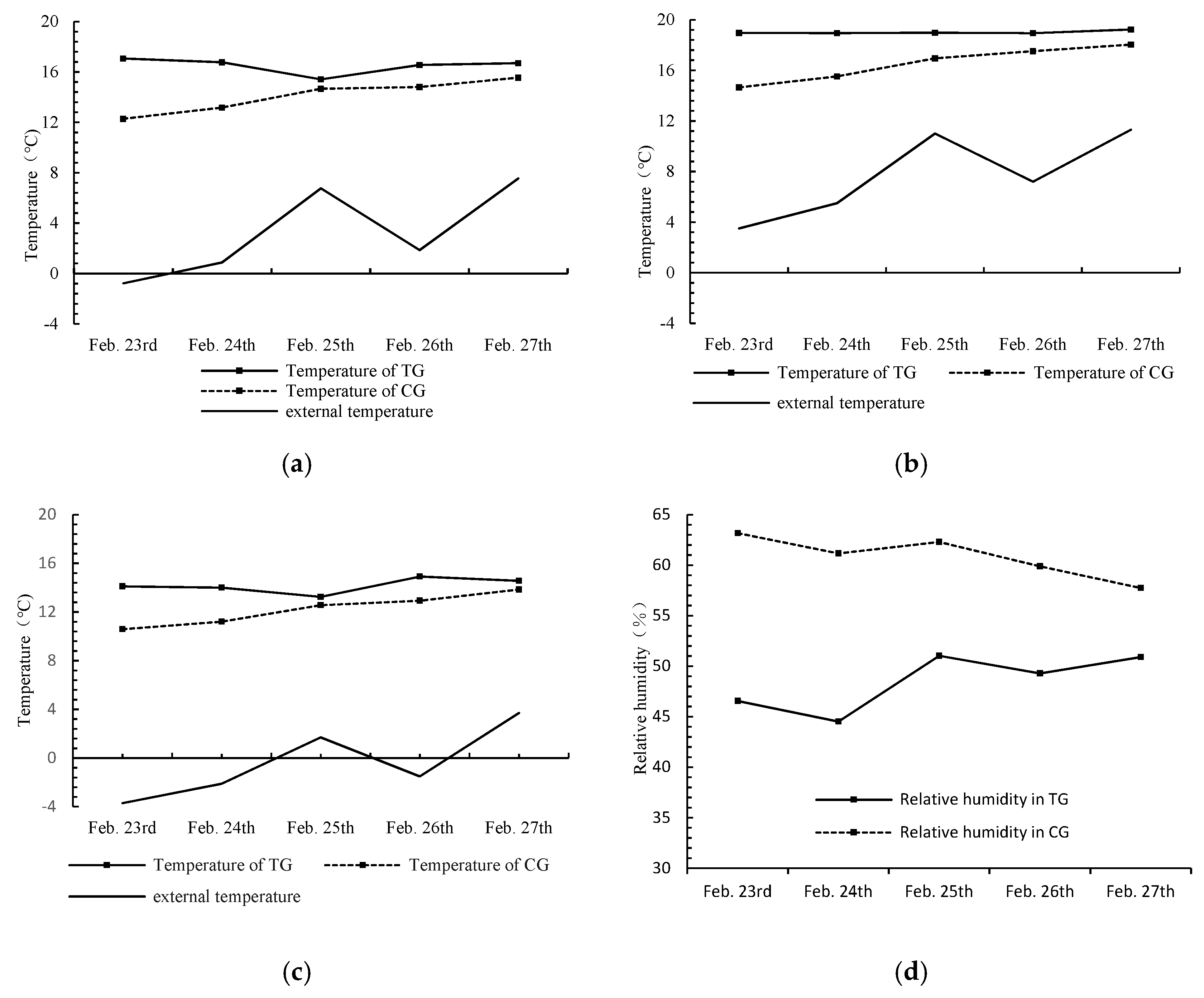
4.1.1. Daytime Operation

During the daytime (10:00 to 16:00) from 23 to 27 February 2022, the indoor and outdoor temperature changes of TG and CG are shown in Figure 4. The average daily temperature (Figure 4a) in TG varied between 28.8 °C and 35.0 °C, in CG between 30.6 °C and 38.5 °C, and externally between 14.1 °C and 21.2 °C. The average daily indoor temperatures of both TG and CG were higher than the outdoor temperature, and the average daily temperature of TG was about 3 °C lower than that of CG.
The maximum daily temperature in TG (Figure 4b) was 31.7 °C to 37.8 °C, in CG it varied between 35.9 °C and 42.5 °C, and externally it varied between 19.0 °C and 25.2 °C. The maximum indoor daily temperatures of both TG and CG were higher than the external temperature, and the maximum temperature of TG was about 4 °C lower than that of CG. This shows that the midday system works stably in the greenhouse operation scenario and has an obvious cooling effect on the greenhouse.

4.1.2. Nighttime Operation

During the night from 23 to 27 February 2022 (21:00 to 8:00 the next day), the average indoor temperatures in TG and CG, the average external temperature, and the average nighttime relative humidity in the greenhouses are presented in Figure 5.
The average night temperature in TG (Figure 4a) varied between 15.4 °C and 17.1 °C, in CG it varied between 12.3 °C and 15.5 °C, and externally it varied between −0.8 °C and 7.5 °C. The nighttime average indoor temperature of both TG and CG was higher than the external temperature, and the nighttime average temperature of TG was about 2 °C higher than that of CG.
The maximum nighttime temperature in TG (Figure 4b) varied between 19.0 °C and 19.2 °C, in CG between 14.7 °C and 18.0 °C, and externally between 3.5 °C and 11.3 °C. The maximum indoor temperature at night in both TG and CG was higher than the external temperature, and the maximum temperature at night in TG was about 2 °C higher than that in CG.
The minimum nighttime temperature in the TG (Figure 5c) varied between 13.3 °C and 14.9 °C, in CG between 10.6 °C and 13.9 °C, and externally between −3.7 °C and 3.7 °C. The night minimum indoor temperature in both greenhouses was higher than the external temperature, and the night minimum temperature in TG was about 3 °C higher than that in CG. Therefore, the results show that the system is effective for greenhouse heating at night.
The growth of greenhouse crops not only needs a suitable temperature environment, but a good environment in terms of humidity also needs to be maintained. Figure 5d shows the changes of indoor relative humidity in TG and CG at night (21:00 to 8:00 the next day) during the experimental period from 23 to 27 February 2022. As can be seen from the figure, the nighttime relative humidity in TG varied between 44.5% and 51.0%, and in CG between 57.7% and 63.2%. The average nighttime humidity of TG was about 20% lower than that of CG. It can be seen that the system has not only provided heating at night, but it has also reduced the nighttime relative humidity and can hence be used to effectively avoid the occurrence of low temperatures and high humidity inside greenhouses, thereby reducing the probability of pests and diseases.

4.2. Energy Saving

Considering the energy stability and energy consumption costs of greenhouse systems and in order to effectively measure the efficiency of clean energy utilization and equipment energy consumption reduction, this paper analyzed the energy saving effect. The associated system performance diagrams are presented in Figure 6.
Figure 6a shows the daytime power consumption of the system, the net increase in the temperature in the energy storage tank and the COP value of the system when operating under the heat storage mode. The power consumption of the system in the daytime heat storage mode between January 23 to 27 was 4.74 kW·h, 4.79 kW·h, 4.29 kW·h, 1.53 kW·h, and 1.66 kW·h, respectively. During these test days, the net increase in the water temperature in the energy storage tank was 17.5 K, 18.4 K, 19.8 K, 3.3 K, and 4.3 K, respectively. These increases can be converted into heat energy gains of 36,750 kJ, 38,640 kJ, 41,580 kJ, 6930 kJ, and 9030 kJ, respectively. Hence, it can be seen that the system consumed low amounts of electricity, significantly reduced the temperature of the greenhouse, and also stored the excess heat from inside the greenhouse. The performance of the energy storage tank in the daytime is summarized in Table 2. At this time, the COP of the system heat storage mode varied between 2.44 and 4.23, indicating that the system had good heat storage performance and energy saving performance in typical weather conditions of the study area.
During the test period from 23 to 27 February 2022 at night (21:00 to 8:00 the next day), the system power consumption and the net reduction in the water temperature in the energy storage tank are shown in Figure 6b. The nighttime power consumption on the 23rd, 24th, 25th, 26th, and 27th was 35.76 kW·h, 30.14 kW·h, 14.42 kW·h, 18.70 kW·h, and 4.90 kW·h, respectively. The net reduction in water temperature in the energy storage tank was 16.5 K, 20.1 K, 11.8 K, 16.4 K, and 4.0 K, respectively. The performance of the energy storage tank during the nighttime is summarized in Table 3. It can be seen that the heat pump system, using the energy storage tank, could not only store excess heat energy in the daytime cooling (with active heat storage) mode but also release the stored heat energy at night to improve the temperature of the greenhouse at that time and hence provide “peak cutting and valley filling” in relation to the heat in the greenhouse.

4.3. Heat Energy Utilization Efficiency of the Energy Storage Tank

In spring, a sunlit greenhouse usually has high internal temperatures in the daytime and low temperatures and high humidity at night. It can be seen from the conclusions of the previous two sections that the active heat storage and release ASHP system can effectively reduce the daytime temperature in a greenhouse, thereby achieving a more suitable environment for crops. At the same time, it can store the excess heat energy from the daytime period in an energy storage tank and subsequently release that energy in order to raise the temperature and reduce the relative humidity of the greenhouse at night. The energy utilization rate of the storage tank is presented in Table 4. During the test period, the lowest temperature of the energy storage tank was higher than the lowest threshold temperature, and the energy utilization efficiency varied between 59.6% and 497.0%. When the temperature of the water tank was higher than the outdoor temperature at night, the system automatically extracted heat from the water tank. If the temperature of the water tank remained higher than the outdoor temperature for a long time and the heat demand of the greenhouse is large, the energy utilization rate will be higher than 100%, as seen on February 24 and February 26. The stored heat energy is released at night to meet the demand for heat in the greenhouse at night. Therefore, the system not only provides a good temperature control and dehumidification function, but it also provides an obvious energy saving effect and high energy utilization rate.

5. Conclusions

In order to address the large temperature differences between day and night, and the poor energy utilization, of a typical greenhouse, this paper proposes an active heat storage and release ASHP greenhouse environmental control system. The energy saving effect of the proposed system was tested, and the stability and energy saving performance of the proposed system were demonstrated. The main research conclusions are as follows:
(1) The active heat storage and release ASHP system proposed in this paper can store the excess heat energy from a greenhouse in the daytime in an energy storage tank. This energy can be then used to avoid low temperatures in the greenhouse at night. The use of the energy storage tank can effectively balance the internal heat of the greenhouse during the day and night, achieve “peak cutting and valley filling” of the internal temperature, and hence, reduce energy consumption.
(2) The proposed system has an obvious effect on the temperature adjustment of a solar greenhouse. During the day, a greenhouse can be cooled by up to 5 °C. At night, the average temperature inside a greenhouse is increased by 2 °C to 3 °C, and the humidity is reduced by about 20%. Hence, the system can provide a stable and suitable environment for the growth of crops.
(3) The active heat storage and release ASHP system proposed in this paper has more stable performance, a greater energy saving effect, and obvious energy efficiency advantages. In the cooling mode, the COP of the system reached 4.32. The heat energy released at night accounted for 26.9% to 51.2% of the electric energy consumption, and the energy utilization efficiency of the energy storage tank varied between 59.6% and 497.0%.
This study provides a new way for the green development of solar greenhouses. The ASHP system developed here not only solves the problem of poor operation under extreme, low-temperature weather conditions, but it also broadens the application range of heat pump systems. The proposed design can be used to improve the utilization rate of clean energy in agricultural production and hence promote agricultural modernization. The proposed optimized system has a broad application prospect and can provide an effective reference for the development of smart agriculture.
Although the system ran for a long time during the test, it did not encounter a cloudy day, so the system performance under this weather condition could not be tested. At the same time, due to the operation of the system, the solar greenhouse is in a relatively closed state, and the problem of CO2 supply has not been considered in this study. Periodic ventilation may be a more ideal method.
The application of this system in a solar greenhouse is good, but there is still a lot of room for improvement. The capacity of the energy storage tank, the selection of the energy storage medium in the energy storage tank, the combination of the system with solar energy and other equipment, and the interaction with greenhouse crops are the next research objectives.

Author Contributions

Conceptualization, Y.X. and X.S.; funding acquisition, C.Z., M.S. and C.L.; data curation, Y.C. (Yifan Cao), X.G., Y.L., W.W. and M.S.; supervision, X.S.; project administration, C.Z.; methodology, Y.X.; software, Y.C. (Yangda Chen), C.Z.; writing—original draft, C.L., Y.X. and M.S.; writing—review and editing, X.S., Y.X. and C.L. All authors have read and agreed to the published version of the manuscript.

Funding

This research was funded by National Technical System of Bulk Vegetable Industry (CARS-23-C-05), Shaanxi Provincial Technology Innovation Guidance Special Fund (2021QFY08-02), and Shaanxi Science and Technology Innovation Team (2021TD-34).

Data Availability Statement

The data used to support the findings of this study are available from the corresponding author upon reasonable request.

Conflicts of Interest

The authors declare no conflict of interest.

References

  1. Abedrabboh, O.; Koç, M.; Biçer, Y. Modelling and analysis of a renewable energy-driven climate-controlled sustainable greenhouse for hot and arid climates. Energy Convers. Manag. 2022, 273, 116412. [Google Scholar] [CrossRef]
  2. Zhu, R.; Wong, M.S.; Kwan, M.-P.; Chen, M.; Santi, P.; Ratti, C. An economically feasible optimization of photovoltaic provision using real electricity demand: A case study in New York city. Sustain. Cities Soc. 2022, 78, 103614. [Google Scholar] [CrossRef]
  3. Sommer, B.; Pont, U.; Moncayo, G.; Bauer, P.; Braun, J.; Sommer-Nawara, M.; Prieler, I.; Brus, T.; Mahdavi, A. Recent progress of SPIDER: Aspects of subtractive approaches to existing building’s performance improvement. J. Phys. Conf. Ser. 2021, 2069, 012086. [Google Scholar] [CrossRef]
  4. Vorushylo, I.; Keatley, P.; Shah, N.; Green, R.; Hewitt, N. How heat pumps and thermal energy storage can be used to manage wind power: A study of Ireland. Energy 2018, 157, 539–549. [Google Scholar] [CrossRef]
  5. Aye, L.; Fuller, R.J.; Canal, A. Evaluation of a heat pump system for greenhouse heating. Int. J. Therm. Sci. 2010, 49, 202–208. [Google Scholar] [CrossRef] [Green Version]
  6. Yang, S.; Rhee, J.Y. Utilization and performance evaluation of a surplus air heat pump system for greenhouse cooling and heating. Appl. Energy 2013, 105, 244–251. [Google Scholar] [CrossRef]
  7. Ibrahim, O.; Fardoun, F.; Younes, R.; Louahlia-Gualous, H. Air source heat pump water heater: Dynamic modeling, optimal energy management and mini-tubes condensers. Energy 2014, 64, 1102–1116. [Google Scholar] [CrossRef]
  8. Rosenow, J.; Gibb, D.; Nowak, T.; Lowes, R. Heating up the global heat pump market. Nat. Energy 2022, 7, 901–904. [Google Scholar] [CrossRef]
  9. Carroll, P.; Chesser, M.; Lyons, P. Air source heat pumps field studies: A systematic literature review. Renew. Sustain. Energy Rev. 2020, 134, 110275. [Google Scholar] [CrossRef]
  10. Singh, V.; Dincer, I.; Rosen, M.A. Investigation of new mechanical heat pump systems for heat upgrading applications. Int. J. Energy Res. 2018, 42, 3078–3090. [Google Scholar] [CrossRef]
  11. Oruc, O.; Dincer, I.; Javani, N. Application of a ground source heat pump system with PCM-embedded radiant wall heating for buildings. Int. J. Energy Res. 2019, 43, 6542–6550. [Google Scholar] [CrossRef]
  12. Gerami Moghaddam, I.; Saniei, M.; Mashhour, E. Improvement of energy performance employing electrical heat pump in scheduling a residential energy hub. Int. Trans. Electr. Energy Syst. 2016, 26, 2618–2642. [Google Scholar] [CrossRef]
  13. Togashi, E. Development of heat pump model based on outlet temperature of heat medium. Jpn. Arch. Rev. 2018, 1, 129–139. [Google Scholar] [CrossRef] [Green Version]
  14. Sun, R.; Luo, H.; Li, Z.; Li, Z.; Hui, C. Research Status of Air Source Heat Pump Heating Technology. Ind. Saf. Environ. Prot. 2021, 47, 99–102. [Google Scholar]
  15. Tang, X.; Zhang, L. Discussion on Application Technology of Low Temperature Air Source Heat Pump. Sci. Technol. Innov. Appl. 2015, 144. [Google Scholar]
  16. Youssef, W.; Ge, Y.T.; Tassou, S.A. Effects of latent heat storage and controls on stability and performance of a solar assisted heat pump system for domestic hot water production. Sol. Energy 2017, 150, 394–407. [Google Scholar] [CrossRef]
  17. Chen, K.; Zuo, Y.; Li, H.; Qi, C.; Liu, H.; Ben, Z. Design and Experiment of Heat Pump Low-temperature Circulating Grain Dryer Control System. Trans. Chin. Soc. Agric. Mach. 2021, 52, 316–323. [Google Scholar] [CrossRef]
  18. Liu, Y.; Bian, Y.; Guo, X.; Liu, Y.; Wang, H. Drying Characteristics and Mathematical Model of Air-dried Chestnut by Combined Solar Energy and Heat Pump. Trans. Chin. Soc. Agric. Mach. 2020, 51, 509–516. [Google Scholar]
  19. Caird, S.; Roy, R.; Potter, S. Domestic heat pumps in the UK: User behaviour, satisfaction and performance. Energy Effic. 2012, 5, 283–301. [Google Scholar] [CrossRef] [Green Version]
  20. Kelly, N.; Cockroft, J. Analysis of retrofit air source heat pump performance: Results from detailed simulations and comparison to field trial data. Energy Build. 2011, 43, 239–245. [Google Scholar] [CrossRef] [Green Version]
  21. Le, K.X.; Huang, M.J.; Shah, N.N.; Wilson, C.; Mac Artain, P.; Byrne, R.; Hewitt, N.J. Techno-economic assessment of cascade air-to-water heat pump retrofitted into residential buildings using experimentally validated simulations. Appl. Energy 2019, 250, 633–652. [Google Scholar] [CrossRef]
  22. Allison, J.; Cowie, A.; Galloway, S.; Hand, J.; Kelly, N.J.; Stephen, B. Simulation, implementation and monitoring of heat pump load shifting using a predictive controller. Energy Convers. Manag. 2017, 150, 890–903. [Google Scholar] [CrossRef] [Green Version]
  23. Hailin, L. Numerical Study and Analysis on the Performance of the Series-type and Parallel-type Heating Systems of Solar Assisted Air Source Heat Pump in Lanzhou Region; Lanzhou University of Technology: Lanzhou, China, 2019. [Google Scholar]
  24. Yan, C. Experiment and Simulation Study on Solar-Assisted Air Source Heat Pump for Space Heating; Tianjin University: Tianjin, China, 2006. [Google Scholar]
  25. Qianru, L. Study on the Application of Solar-Air Source Combined Heating System in Plateau Cold Regions; Chongqing University: Chongqing, China, 2018. [Google Scholar]
  26. Ma, R.; Mao, C.; Shan, M.; Zhang, L.; Yang, X. Occupant control patterns of low temperature air-to-air heat pumps in Chinese rural households based on field measurements. Energy Build. 2017, 154, 157–165. [Google Scholar] [CrossRef]
  27. Bing, C.; Xiao-lin, L.; Fang-lin, B.; Jie, L. Experiment on greenhouse solar energy associated with air-source heat pump heating system. J. Agric. Sci. Technol. 2011, 13, 55–59. [Google Scholar]
  28. Xianpeng, S.; Kangquan, G.; Zhirong, Z.; Yue, Z. System investigation of a solar combined with air-source heat pump system for greenhouse heating. J. Sol. Energy 2016, 37, 658–665. [Google Scholar]
  29. Xianpeng, S.; Zhirong, Z.; Kang, Z.; Shengshan, B.; Kang-quan, G. Experiment on heating effect in greenhouse by solar combined with air-source heat pump. Trans. Chin. Soc. Agric. Eng. 2015, 31, 215–221. [Google Scholar]
  30. Yuxin, Z.; Shuai, Z.; Jie, L. Characteristic analysis and evaluation of solar and air source heat pump compound heating system applied in Xi ’an area. Sol. Energy J. 2021, 36–43. [Google Scholar] [CrossRef]
  31. Xingran, L. Preliminary Study on Mechanism and Greenhouse Application Experiment of Wind Stirring Heating Technology; North West Agriculture and Forestry University: Xianyang, China, 2022. [Google Scholar]
Figure 1. The active heat storage and release ASHP system as developed in this study. (a) External unit, and (b) energy storage tank (left) and internal unit (right).
Energies 16 00089 g001
Figure 2. Schematic diagram of active storage and release ASHP system.
Energies 16 00089 g002
Figure 3. Schematic diagram of the experimental solar greenhouse and the layout of internal (A1 to A5 and C) and external (B) measuring points.
Energies 16 00089 g003
Figure 4. Comparison of daytime temperatures in TG, CG, and externally. (a) Comparison of average daytime temperatures, and (b) comparison of daytime maximum temperatures.
Energies 16 00089 g004
Figure 5. Comparison of temperature and humidity in TG, CG, and externally at night. (a) Comparison of nighttime average temperature, (b) comparison of maximum temperature at night, (c) comparison of minimum temperature at night, and (d) comparison of average relative humidity at night.
Energies 16 00089 g005
Figure 6. Performance diagrams of the active heat storage and release ASHP system. (a) Daytime system performance diagram, and (b) nighttime system performance diagram.
Energies 16 00089 g006
Table 1. Performance parameters of the active heat storage and release ASHP system.
ParameterNumerical ValueParameterNumerical ValueParameterNumerical Value
Unit cooling capacity15.6 kWUnit heat production20.5 kWRefrigerant modelR22
Rated refrigeration input power5.6 kWRated heating input power5.3 kWThe circulation principleInverse Carnot cycle
Coefficient of refrigeration performance2.7Coefficient of heating performance3.0
Table 2. Performance of the energy storage tank in the daytime from 23 February to 27 February 2022.
Date (Day)Feb. 23rdFeb. 24thFeb. 25thFeb. 26thFeb. 27th
Energy storage tank for daytime heat (kJ)36,75038,64041,58069309030
Conversion of heat energy to electric energy (kW·h)10.2110.7311.551.932.51
The proportion of the heat stored in the daytime energy storage tank to the electricity consumed during the day215.4%224.0%269.2%126.1%151.2%
Table 3. Performance of the energy storage tank at night from 23 February to 27 February 2022.
Date (Day)Feb. 23rdFeb. 24thFeb. 25thFeb. 26thFeb. 27th
Energy storage tank releases heat energy at night (kJ)34,65042,21024,78034,4408400
Conversion of heat energy to electric energy (kW·h)9.6311.736.839.572.33
The proportion of the heat energy released by the nighttime energy storage tank to the electric energy consumed at night26.9%38.9%47.7%51.2%47.6%
Table 4. Energy utilization rate of energy storage water tank from 23 February to 27 February 2022.
Date (Day)Feb. 23rdFeb. 24thFeb. 25thFeb. 26thFeb. 27th
Energy storage tank for daytime heat (kJ)36,75038,64041,58069309030
Energy storage tank releases heat energy at night (kJ)34,65042,21024,78034,4408400
Energy utilization efficiency94.3%109.2%59.6%497.0%93.0%
Disclaimer/Publisher’s Note: The statements, opinions and data contained in all publications are solely those of the individual author(s) and contributor(s) and not of MDPI and/or the editor(s). MDPI and/or the editor(s) disclaim responsibility for any injury to people or property resulting from any ideas, methods, instructions or products referred to in the content.

