


Gel Fuels: Preparing, Rheology, Atomization, Combustion

Abstract
:1. Introduction
2. Fuel Preparation
3. Rheology
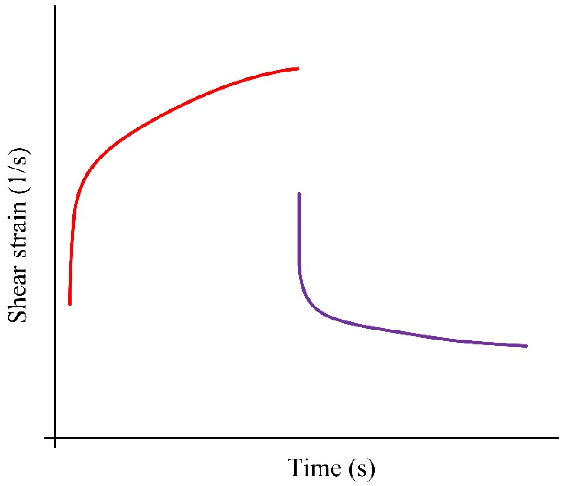
3.1. Shear Strain
3.2. Rheological and Physical–Mechanical Characteristics
3.2.1. Viscosity
- Low (less than 1 s−1);
- Medium (from 1 to 105 s−1);
- High (more than 105 s−1).
3.2.2. Tensile Strength
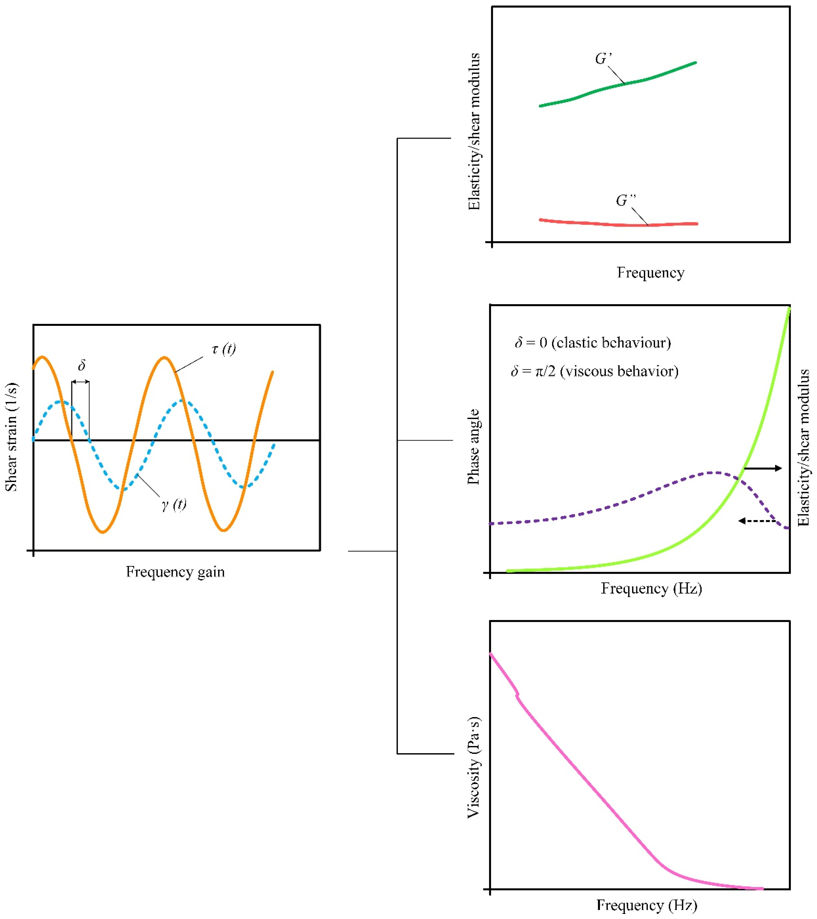
3.2.3. Viscoelastic Properties
3.2.4. Thixotropy
4. Atomization
4.1. Main Characteristics of Atomization
4.1.1. Breakup Length
4.1.2. Spray Angle
4.1.3. Droplet Size Distribution
5. Combustion
5.1. Experimental Investigation of Ignition and Combustion of Gel Fuel
- Formation of a large number of bubbles in the near-surface layer of the droplet;
- An increase in the number and size of the bubbles, accompanied by a significant change in the shape of the drop;
- Collapse of bubbles and dispersion of the initial droplet with the separation of a group of droplets of a significantly smaller size (1–2 orders smaller than the initial size of the fuel particle);
- The previous process is accompanied by the release of combustible liquid vapor into the oxidizer medium through the thickener layer (outer shell) when the droplet is destroyed;
- When the limiting conditions are reached, gas-phase ignition occurs in the vicinity of the droplet.
5.2. Mathematical Models of Ignition Processes
6. Conclusions
6.1. Fuel Composition
6.2. Rheology
6.3. Atomization
6.4. Combustion
Author Contributions
Funding
Conflicts of Interest
References
- Carasillo, D.A. Liquid Fuels: Types, Properties and Production; Nova Science: New York, NY, USA, 2012; ISBN 9781614704355. [Google Scholar]
- Houghton-Alico, D. Alcohol Fuels: Policies, Production, and Potential; Taylor & Francis: Abingdon, UK, 2019; ISBN 9780429704642. [Google Scholar]
- De Souza-Santos, M.L. Solid Fuels Combustion and Gasification: Modeling, Simulation, and Equipment Operations, 2nd ed.; CRC Press: Boca Raton, FL, USA, 2010; ISBN 9781420047509. [Google Scholar]
- Tillman, D.; Duong, D.; Harding, N.S. Solid Fuel Blending; Butterworth-Heinemann: Oxford, UK, 2012; ISBN 9780123809322. [Google Scholar]
- Müller, H.; Kiefer, J. Fuels|Gaseous. In Encyclopedia of Analytical Science; Elsevier: Amsterdam, The Netherlands, 2019; ISBN 9780081019832. [Google Scholar]
- Shah, Y.T. Chemical Energy from Natural and Synthetic Gas; CRC Press: Boca Raton, FL, USA, 2017; ISBN 9781315302348. [Google Scholar]
- Verhelst, S.; Turner, J.W.; Sileghem, L.; Vancoillie, J. Methanol as a Fuel for Internal Combustion Engines. Prog. Energy Combust. Sci. 2019, 70, 43–88. [Google Scholar] [CrossRef] [Green Version]
- Li, X.; Qin, S.; Huang, X.; Liu, H. Multi-Component Effect and Reaction Mechanism for Low-Temperature Ignition of Kerosene with Composite Enhancer. Combust. Flame 2019, 199, 401–410. [Google Scholar] [CrossRef]
- Sakaki, K.; Kakudo, H.; Nakaya, S.; Tsue, M.; Suzuki, K.; Kanai, R.; Inagawa, T.; Hiraiwa, T. Combustion Characteristics of Ethanol/Liquid-Oxygen Rocket-Engine Combustor with Planar Pintle Injector. J. Propuls. Power 2017, 33, 514–521. [Google Scholar] [CrossRef]
- García-Contreras, R.; Martínez, J.D.; Armas, O.; Murillo, R.; García, T. Study of a Residential Boiler under Start-Transient Conditions Using a Tire Pyrolysis Liquid (TPL)/Diesel Fuel Blend. Fuel 2015, 158, 744–752. [Google Scholar] [CrossRef]
- Glushkov, D.O.; Kuznetsov, G.V.; Chebochakova, D.A.; Lyakhovskaya, O.E.; Shlegel, N.E.; Anufriev, I.S.; Shadrin, E.Y. Experimental Study of Coal Dust Ignition Characteristics at Oil-Free Start-up of Coal-Fired Boilers. Appl. Therm. Eng. 2018, 142, 371–379. [Google Scholar] [CrossRef]
- Li, Y.; Zhang, X.; Zhang, J.; Zhou, J.; Yan, H. Numerical Simulation and Optimization of Pulverized Coal Injection with Enriched Oxygen into Blast Furnace. Appl. Therm. Eng. 2014, 67, 72–79. [Google Scholar] [CrossRef]
- Padwal, M.B.; Varma, M. Thermal Decomposition and Combustion Characteristics of HTPB-Coarse AP Composite Solid Propellants Catalyzed with Fe2O3. Combust. Sci. Technol. 2018, 190, 1614–1629. [Google Scholar] [CrossRef]
- Emami, M.D.; Shahbazian, H.; Sunden, B. Effect of Operational Parameters on Combustion and Emissions in an Industrial Gas Turbine Combustor. J. Energy Resour. Technol. Trans. ASME 2019, 141, 012202. [Google Scholar] [CrossRef]
- Dubinin, A.M.; Shcheklein, S.E. Mini Coal-Fired CHP Plant on the Basis of Synthesis Gas Generator (CO + H2) and Electrochemical Current Generator. Int. J. Hydrogen Energy 2017, 42, 26048–26058. [Google Scholar] [CrossRef]
- Vershinina, K.Y.; Glushkov, D.O.; Kuznetsov, G.V.; Strizhak, P.A. Differences in the Ignition Characteristics of Coal–Water Slurries and Composite Liquid Fuel. Solid Fuel Chem. 2016, 50, 88–101. [Google Scholar] [CrossRef]
- Miccio, F.; Raganati, F.; Ammendola, P.; Okasha, F.; Miccio, M. Fluidized Bed Combustion and Gasification of Fossil and Renewable Slurry Fuels. Energies 2021, 14, 7766. [Google Scholar] [CrossRef]
- Strizhak, P.A.; Piskunov, M.V.; Volkov, R.S.; Legros, J.C. Evaporation, Boiling and Explosive Breakup of Oil–Water Emulsion Drops under Intense Radiant Heating. Chem. Eng. Res. Des. 2017, 127, 72–80. [Google Scholar] [CrossRef]
- Glushkov, D.O.; Kuznetsov, G.V.; Nigay, A.G.; Yashutina, O.S. Heat and Mass Transfer Induced by the Ignition of Single Gel Propellant Droplets. J. Energy Inst. 2019, 92, 1944–1955. [Google Scholar] [CrossRef]
- Padwal, M.B.; Natan, B.; Mishra, D.P. Gel Propellants. Prog. Energy Combust. Sci. 2021, 83, 100885. [Google Scholar] [CrossRef]
- Tabakaev, R.; Shanenkov, I.; Kazakov, A.; Zavorin, A. Thermal Processing of Biomass into High-Calorific Solid Composite Fuel. J. Anal. Appl. Pyrolysis 2017, 124, 94–102. [Google Scholar] [CrossRef]
- Feng, S.; He, B.; He, H.; Su, L.; Hou, Z.; Nie, W.; Guo, X. Experimental Studies the Burning Process of Gelled Unsymmetrical Dimethylhydrazine Droplets under Oxidant Convective Conditions. Fuel 2013, 111, 367–373. [Google Scholar] [CrossRef]
- Mishra, D.P.; Patyal, A.; Padhwal, M. Effects of Gellant Concentration on the Burning and Flame Structure of Organic Gel Propellant Droplets. Fuel 2011, 90, 1805–1810. [Google Scholar] [CrossRef]
- Natan, B.; Rahimi, S. The Status of Gel Propellants in Year 2000. Int. J. Energetic Mater. Chem. Propuls. 2001, 5, 172–194. [Google Scholar] [CrossRef]
- Tsutsuran, V.I.; Petrukhin, N.V.; Gusev, S.A. Military and Technical Analysis of a State and Prospect of Development of Rocket Fuels; MO RF: Moscow, Russia, 1999. [Google Scholar]
- Klapötke, T.M. Chemistry of High-Energy Materials; Walter de Gruyter GmbH: Berlin, Germany, 2015. [Google Scholar]
- Zeldovich, Y.B.; Barenblatt, G.I.; Librovich, V.B.; Makhviladze, G.M. Mathematical Theory of Combustion and Explosions; Plenum: New York, NY, USA, 1985. [Google Scholar]
- Williams, F.A. Combustion Theory; Westview Press: Boulder, CO, USA, 1985. [Google Scholar]
- Merzhanov, A.G.; Khaikin, B.I. Theory of Combustion Waves in Homogeneous Media. Prog. Energy Combust. Sci. 1988, 14, 1–98. [Google Scholar] [CrossRef]
- Vilyunov, V.N.; Zarko, V.E. Ignition of Solids; Elsevier: Amsterdam, The Netherlands, 1989. [Google Scholar]
- Okajima, S.; Kumagai, S. Further Investigations of Combustion of Free Droplets in a Freely Falling Chamber Including Moving Droplets. Symp. Combust. 1975, 15, 401–407. [Google Scholar] [CrossRef]
- Manzhai, V.N.; Fufaeva, M.S. Polyvinyl Alcohol Cryogels as an Efficient Spent-Oil Utilization Method. Chem. Technol. Fuels Oils 2015, 51, 487–492. [Google Scholar] [CrossRef]
- Dove, M.F.A.; Logan, N.; Mauger, J.P.; Allan, B.D.; Arndt, R.E.; Hawk, C.W. Aluminum Alloy Compatibility with Gelled Inhibited Red Fuming Nitric Acid. J. Propuls. Power 1996, 12, 585–590. [Google Scholar] [CrossRef]
- Padwal, M.B.; Mishra, D.P. Synthesis of Jet A1 Gel Fuel and Its Characterization for Propulsion Applications. Fuel Process. Technol. 2013, 106, 359–365. [Google Scholar] [CrossRef]
- Gupta, B.L.; Varma, M.; Munjal, N.L. Rheological Studies on Virgin and Metallized Unsymmetrical Dimethyl Hydrazine Gelled Systems. Propellants, Explos. Pyrotech. 1986, 11, 45–52. [Google Scholar] [CrossRef]
- Verma, M.; Gupta, B.L.; Pandey, M. Formulation & Storage Studies on Hydrazine-Based Gelled Propellants. Def. Sci. J. 1996, 46, 435–442. [Google Scholar] [CrossRef] [Green Version]
- Varghese, T.L.; Gaindhar, S.C.; David, J.; Jose, J.; Muthiah, R.; Rao, S.S.; Ninan, K.N.; Krishnamurthy, V.N. Developmental Studies on Metallised UDMH and Kerosene Gels. Def. Sci. J. 1995, 45, 25–30. [Google Scholar] [CrossRef] [Green Version]
- Arnold, R.; Santos, P.H.S.; Campanella, O.H.; Anderson, W.E. Rheological and Thermal Behavior of Gelled Hydrocarbon Fuels. J. Propuls. Power 2011, 27, 151–161. [Google Scholar] [CrossRef]
- Martinez-Pastor, J.; Franco, P.; Oton-Martinez, R.A. Rheology of Double-Base Gelled Propellants as the Basis for Extrusion Process Modelling: Influence of Normal Force on Slip Layer and Flow Curves. Int. J. Mater. Form. 2020, 13, 219–233. [Google Scholar] [CrossRef]
- Jyoti, B.V.S.; Baek, S.W. Rheological Characterization of Metalized and Non-Metalized Ethanol Gel Propellants. Propellants, Explos. Pyrotech. 2014, 39, 866–873. [Google Scholar] [CrossRef]
- Rahimi, S.; Natan, B. The Flow of Gel Fuels in Tapered Injectors. J. Propuls. Power 2000, 16, 458–464. [Google Scholar] [CrossRef]
- Mansour, A.; Chigier, N. Air-Blast Atomization of Non-Newtonian Liquids. J. Non-Newton. Fluid Mech. 1995, 58, 161–194. [Google Scholar] [CrossRef]
- Guan, H.-S.; Li, G.-X.; Zhang, N.-Y. Experimental Investigation of Atomization Characteristics of Swirling Spray by ADN Gelled Propellant. Acta Astronaut. 2018, 144, 119–125. [Google Scholar] [CrossRef]
- Fu, Q.-F.; Duan, R.-Z.; Cui, K.-D.; Yang, L.-J. Spray of Gelled Propellants from an Impinging-Jet Injector under Different Temperatures. Aerosp. Sci. Technol. 2014, 39, 552–558. [Google Scholar] [CrossRef]
- Nachmoni, G.; Natan, B. Combustion Characteristics of Gel Fuels. Combust. Sci. Technol. 2000, 156, 139–157. [Google Scholar] [CrossRef]
- Galecki, D.L. Ignition and Combustion of Metallized Propellants. In Proceedings of the 25th Joint Propulsion Conference, Monterey, CA, USA, 12–16 July 1989; p. AIAA 1989-2883. [Google Scholar]
- He, B.; Nie, W.; He, H. Unsteady Combustion Model of Nonmetalized Organic Gel Fuel Droplet. Energy Fuels 2012, 26, 6627–6639. [Google Scholar] [CrossRef]
- Mishra, D.P.; Patyal, A. Effects of Initial Droplet Diameter and Pressure on Burning of ATF Gel Propellant Droplets. Fuel 2012, 95, 226–233. [Google Scholar] [CrossRef]
- Manzhai, V.N.; Fufaeva, M.S.; Egorova, L.A. Fuel Briquettes Based on Finely Dispersed Coke Particles and Polyvinyl Alcohol Cryogels. Solid Fuel Chem. 2013, 47, 43–46. [Google Scholar] [CrossRef]
- Ciezki, H.K.; Naumann, K.W. Some Aspects on Safety and Environmental Impact of the German Green Gel Propulsion Technology. Propellants Explos. Pyrotech. 2016, 41, 539–547. [Google Scholar] [CrossRef]
- Kukushkin, V.; Ivanchenko, A. The Pasty Propellant Rocket Engines Development. In Proceedings of the 29th Joint Propulsion Conference and Exhibit, Monterey, CA, USA, 28–30 June 1993; p. AIAA 1993-1754. [Google Scholar]
- Palaszewski, B.; Powell, R. Launch Vehicle Performance Using Metallized Propellants. J. Propuls. Power 1994, 10, 828–833. [Google Scholar] [CrossRef] [Green Version]
- Moghaddam, A.S.; Rezaei, M.R.; Tavangar, S. Experimental Investigation of Characteristic Length Influence on a Combustion Chamber Performance with Liquid and Gelled UDMH/IRFNA Bi-Propellants. Propellants Explos. Pyrotech. 2019, 44, 1154–1159. [Google Scholar] [CrossRef]
- Rapp, D.C.; Zurawski, R.L. Characterization of Aluminum/RP-1 Gel Propellant Properties. In Proceedings of the 24th Joint Propulsion Conference, Boston, MA, USA, 11–13 July 1988; American Institute of Aeronautics and Astronautics: Reston, VA, USA; p. 25. [Google Scholar]
- Kajiwara, K. Structure of Gels. In Gels Handbook; Osada, Y., Kajiwara, K., Fushimi, T., Irasa, O., Hirokawa, Y., Matsunaga, T., Shimomura, T., Wang, L., Ishida, H., Eds.; Academic Press: London, UK, 2001; Volume 1, pp. 122–171. [Google Scholar]
- Tepper, F.; Lerner, M.I.; Ginley, D.S. Metallic Nanopowders: An Overview. In Dekker Encyclopedia of Nanoscience and Nanotechnology; CRC Press: Boca Raton, FL, USA, 2004; pp. 1921–1934. [Google Scholar]
- Kaledin, L.; Tepper, F. Metallic Nanopowders: Rocket Propulsion. In Dekker Encyclopedia of Nanoscience and Nanotechnology; CRC Press: Boca Raton, FL, USA, 2011; pp. 2165–2175. [Google Scholar]
- Ray, A.B. Process of Producing Solidified Fuel. U.S. Patent 2,046,209, 30 June 1936. [Google Scholar]
- Long, C.G. Reinforced Gelled Propellants. U.S. Patent 3,035,950, 22 May 1962. [Google Scholar]
- Longwell, J.P.; Bieber, H. Gelled Solid Rocket Propellant Reinforced with Unoriented Microfibers. U.S. Patent 3,369,943, 20 February 1968. [Google Scholar]
- Tarpley, W.B. Thixotropic Gel Fuels. U.S. Patent 4,156,594, 29 May 1979. [Google Scholar]
- Tarpley, W.B. Thixotropic Oxidizer Propellant Mixtures. U.S. Patent 3,449,178, 10 June 1969. [Google Scholar]
- Tarpley, W.B. Thixotropic Organic Liquid Propellant Compositions with Solid Storage Characteristics. U.S. Patent 3,471,344, 7 October 1969. [Google Scholar]
- Hodge, K.F.; Crofoot, T.A.; Nelson, S. Gelled Propellants for Tactical Missile Applications. In Proceedings of the 35th Joint Propulsion Conference and Exhibit, Los Angeles, CA, USA, 20–24 June 1999; American Institute of Aeronautics and Astronautics: Reston, Virigina, 1999; pp. 1–7. [Google Scholar]
- Ramasubramanian, C.; Notaro, V.; Lee, J.G. Characterization of Near-Field Spray of Nongelled- and Gelled-Impinging Doublets at High Pressure. J. Propuls. Power 2015, 31, 1642–1652. [Google Scholar] [CrossRef]
- Rahimi, S.; Natan, B. Thixotropic Effect of Inorganic Gel Fuels. J. Propuls. Power 2000, 16, 1182–1184. [Google Scholar] [CrossRef]
- Yoon, C.; Heister, S.D.; Campanella, O.E. Plain-Orifice Gelled Propellant Flow Characteristics with Rheological Hysteresis. In Proceedings of the 48th AIAA/ASME/SAE/ASEE Joint Propulsion Conference and Exhibit, Atlanta, GA, USA, 30 July–1 August 2012; p. AIAA-2012-4135. [Google Scholar]
- Lee, I.; Koo, J. Break-up Characteristics of Gelled Propellant Simulants with Various Gelling Agent Contents. J. Therm. Sci. 2010, 19, 545–552. [Google Scholar] [CrossRef]
- Jejurkar, S.Y.; Yadav, G.; Mishra, D.P. Characterization of Impinging Jet Sprays of Gelled Propellants Loaded with Nanoparticles in the Impact Wave Regime. Fuel 2018, 228, 10–22. [Google Scholar] [CrossRef]
- Jejurkar, S.Y.; Yadav, G.; Mishra, D.P. Visualizations of Sheet Breakup of Non-Newtonian Gels Loaded with Nanoparticles. Int. J. Multiph. Flow 2018, 100, 57–76. [Google Scholar] [CrossRef]
- Mordosky, J.W.; Zhang, B.Q.; Kuo, K.K.; Tepper, F.; Kaledin, L.A. Spray Combustion of Gelled RP-1 Propellants Containing Nano-Sized Aluminum Particles in Rocket Engine Conditions. In Proceedings of the 37th Joint Propulsion Conference and Exhibit, Salt Lake City, UT, USA, 8–11 July 2001; p. AIAA-2001-3274. [Google Scholar]
- McKinney, C.D.; Tarpley, W.B. Gelling of Liquid Hydrogen; NASA-CR-54967; NASA: Washington, DC, USA, 1966. [Google Scholar]
- Staikovich, J.; Adams, S.; Palaszewski, B. Nanoparticulate Gellants for Metallized Gelled Liquid Hydrogen with Aluminum. In Proceedings of the 32nd Joint Propulsion Conference and Exhibit, Lake Buena Vista, FL, USA, 1–3 July 1996; p. AIAA-96-3234. [Google Scholar]
- Wong, W.; Starkovich, J.; Adams, S.; Palaszewski, B. Cryogenic Gellant and Fuel Formulation for Metallized Gelled Propellants: Hydrocarbons and Hydrogen with Aluminum. In Proceedings of the 30th Joint Propulsion Conference cosponsored by AIAA, ASME, SAE, and ASEE, Indianapolis, IN, USA, 27–29 June 1994; p. AIAA-94-3175. [Google Scholar]
- Rahimi, S.; Hasan, D.; Peretz, A. Development of Laboratory-Scale Gel-Propulsion Technology. J. Propuls. Power 2004, 20, 93–100. [Google Scholar] [CrossRef]
- Rahimi, S.; Peretz, A.; Natan, B. Rheological Matching of Gel Propellants. J. Propuls. Power 2010, 26, 376–378. [Google Scholar] [CrossRef]
- Rahimi, S.; Peretz, A.; Natan, B. On Shear Rheology of Gel Propellants. Propellants, Explos. Pyrotech. 2007, 32, 165–174. [Google Scholar] [CrossRef]
- Solomon, Y.; DeFini, S.J.; Pourpoint, T.L.; Anderson, W.E. Gelled Monomethyl Hydrazine Hypergolic Droplet Investigation. J. Propuls. Power 2013, 29, 79–86. [Google Scholar] [CrossRef]
- Cho, K.Y.; Pourpoint, T.L.; Son, S.F.; Lucht, R.P. Microexplosion Investigation of Monomethylhydrazine Gelled Droplet with OH Planar Laser-Induced Fluorescence. J. Propuls. Power 2013, 29, 1303–1310. [Google Scholar] [CrossRef]
- Thynell, S.T.; Adair, J.H.; Goddard, I.W.A.; Hanson, R.K.; Law, C.K.; Lee, J.; Rabitz, H.A.; Risha, G.A.; Williams, F.A.; Yang, V.; et al. Spray and Combustion of Gelled Hypergolic Propellants (Final Report); Pennsylvania State University: University Park, PA, USA, 2014; pp. 1–347. [Google Scholar]
- Padwal, M.B.; Mishra, D.P. Effect of Air Injection Configuration on the Atomization of Gelled Jet A1 Fuel in an Air-Assist Internally Mixed Atomizer. At. Sprays 2013, 23, 327–341. [Google Scholar] [CrossRef]
- Padwal, M.B.; Mishra, D.P. Experimental Characterization of Gelled Jet A1 Spray Flames. Flow Turbul. Combust. 2016, 97, 295–337. [Google Scholar] [CrossRef]
- Jyoti, B.V.S.; Baek, S.W. Formulation and Comparative Study of Rheological Properties of Loaded and Unloaded Ethanol-Based Gel Propellants. J. Energ. Mater. 2015, 33, 125–139. [Google Scholar] [CrossRef]
- Jyoti, B.V.S.; Naseem, M.S.; Baek, S.W. Hypergolicity and Ignition Delay Study of Pure and Energized Ethanol Gel Fuel with Hydrogen Peroxide. Combust. Flame 2017, 176, 318–325. [Google Scholar] [CrossRef]
- Von Kampen, J.; Madlener, K.; Ciezki, H.K. Characteristic Flow and Spray Properties of Gelled Fuels with Regard to the Impinging Jet Injector Type. In Proceedings of the Collection of Technical Papers—AIAA/ASME/SAE/ASEE 42nd Joint Propulsion Conference, Sacramento, CA, USA, 9–12 July 2006; Volume 4, pp. 2639–2650. [Google Scholar]
- Jyoti, B.V.S.; Naseem, M.S.; Baek, S.W.; Lee, H.J.; Cho, S.J. Hypergolicity and Ignition Delay Study of Gelled Ethanolamine Fuel. Combust. Flame 2017, 183, 102–112. [Google Scholar] [CrossRef]
- Weiser, V.; Gläser, S.; Kelzenberg, S.; Eisenreich, N.; Roth, E. Investigations on the Droplet Combustion of Gelled Mono-and Bipropellants. In Proceedings of the 41st AIAA/ASME/SAE/ASEE Joint Propulsion Conference and Exhibit, Tucson, AZ, USA, 10–13 July 2005; p. AIAA-2005-4474. [Google Scholar]
- Boyer, E.; Risha, G.A.; Kuo, K.K.; Devendorf, T.E. Combustion Characteristics of Non-Toxic Non-Hypergolic Bipropellants. In Proceedings of the 38th AIAA/ASME/SAE/ASEE Joint Propulsion Conference and Exhibit, Indianapolis, IN, USA, 7–10 July 2002; p. AIAA-2002-4297. [Google Scholar]
- Tarpley, W.B., Jr. Thixotropic Liquid Propellant Compositions with Solid Storage Characteristics. U.S. Patent 3,470,040, 30 September 1969. [Google Scholar]
- Coguill, S.L. Synthesis of Highly Loaded Gelled Propellants; Technical Report; Resodyn Corp.: Butte, MT, USA, 2009. [Google Scholar]
- Baek, G.; Kim, C. Rheological Properties of Carbopol Containing Nanoparticles. J. Rheol. 2011, 55, 313–330. [Google Scholar] [CrossRef] [Green Version]
- Green, J.; Rapp, D.; Roncace, J. Flow Visualization of a Rocket Injector Spray Using Gelled Propellant Simulants. In Proceedings of the 27th Joint Propulsion Conference, Sacramento, CA, USA, 24–26 June 1991; pp. 1–16. [Google Scholar]
- Terech, P.; Weiss, R.G. Low Molecular Mass Gelators of Organic Liquids and the Properties of Their Gels. Chem. Rev. 1997, 97, 3133–3160. [Google Scholar] [CrossRef]
- Varma, M.; Pein, R. Optimisation of Processing Conditions for Gel Propellant Production. Int. J. Energ. Mater. Chem. Propuls. 2009, 8, 501–513. [Google Scholar] [CrossRef]
- Padwal, M.B.; Mishra, D.P. Characteristics of Gelled Jet A1 Sprays Formed by Internal Impingement of Micro Air Jets. Fuel 2016, 185, 599–611. [Google Scholar] [CrossRef]
- Goldin, M.; Pfeffer, R.; Shinnar, R. Break-up of a Capillary Jet of a Non-Newtonian Fluid Having a Yield Stress. Chem. Eng. J. 1972, 4, 8–20. [Google Scholar] [CrossRef]
- Chernov, V.; Natan, B. Effect of Periodic Disturbances on Non-Newtonian Fluid Sprays. At. Sprays 2008, 18, 723–738. [Google Scholar]
- Arnold, R.; Anderson, W.E. Droplet Burning of JP-8/Silica Gels. In Proceedings of the 48th AIAA Aerospace Sciences Meeting Including the New Horizons Forum and Aerospace Exposition, Orlando, FL, USA, 4–7 January 2010. [Google Scholar] [CrossRef] [Green Version]
- Ciezki, H.K.; Robers, A.; Schneider, G. Investigation of the Spray Behavior of Gelled Jet A-1 Fuels Using an Air Blast and an Impinging Jet Atomizer. In Proceedings of the 38th AIAA/ASME/SAE/ASEE Joint Propulsion Conference and Exhibit, Indianapolis, IN, USA, 7–10 July 2002. [Google Scholar]
- Negri, M.; Ciezki, H.K. Combustion of Gelled Propellants Containing Microsized and Nanosized Aluminum Particles. J. Propuls. Power 2015, 31, 400–407. [Google Scholar] [CrossRef]
- Olson, W.T.; Breitwieser, R. NACA Research on Slurry Fuels through 1954; NACA-RM-E55B14 (21 April 1955); NACA: Washington, DC, USA, 1955; pp. 1–31. [Google Scholar]
- Gany, A. Comprehensive Consideration of Boron Combustion in Air Breathing Combustion. In Proceedings of the 42nd AIAA/ASME/SAE/ASEE Joint Propulsion Conference & Exhibit, Sacramento, CA, USA, 9–12 July 2006; p. AIAA-2006-4567. [Google Scholar]
- Haddad, A.; Natan, B.; Arieli, R. The Performance of a Boron-Loaded Gel-Fuel Ramjet. Prog. Propuls. Phys. 2011, 2, 499–518. [Google Scholar] [CrossRef] [Green Version]
- Natan, B.; Gany, A. Combustion Characteristics of a Boron-Fueled Solid Fuel Ramjet with Aft-Burner. J. Propuls. Power 1993, 9, 694–701. [Google Scholar] [CrossRef]
- Munjal, N.L.; Gupta, B.L.; Varma, M. Preparative and Mechanistic Studies on Unsymmetrical Dimethyl Hydrazine-Red Fuming Nitric Acid Liquid Propellant Gels. Propellants, Explos. Pyrotech. 1985, 10, 111–117. [Google Scholar] [CrossRef]
- Santos, P.H.S.; Arnold, R.; Anderson, W.E.; Carignano, M.A.; Campanella, O.H. Characterization of JP-8/SiO 2 and RP-1/SiO 2 Gels. Eng. Lett. 2010, 18, 41–48. [Google Scholar]
- Brändle, R.; Liebl, J.; Pein, R. Preparation and Characterization of Gelled Fuels. Int. J. Energ. Mater. Chem. Propuls. 2007, 6, 307–321. [Google Scholar] [CrossRef]
- Kim, H.; Ko, T.; Kim, S.; Yoon, W. Spray Characteristics of Aluminized-Gel Fuels Sprayed Using Pressure-Swirl Atomizer. J. Non-Newton. Fluid Mech. 2017, 249, 36–47. [Google Scholar] [CrossRef]
- Vershinina, K.Y.; Glushkov, D.O.; Nigay, A.G.; Yanovsky, V.A.; Yashutina, O.S. Oil-Filled Cryogels: New Approach for Storage and Utilization of Liquid Combustible Wastes. Ind. Eng. Chem. Res. 2019, 58, 6830–6840. [Google Scholar] [CrossRef]
- Glushkov, D.O.; Kuznetsov, G.V.; Nigay, A.G.; Yanovsky, V.A.; Yashutina, O.S. Ignition Mechanism and Characteristics of Gel Fuels Based on Oil-Free and Oil-Filled Cryogels with Fine Coal Particles. Powder Technol. 2020, 360, 65–79. [Google Scholar] [CrossRef]
- Kirsanov, E.A.; Matveenko, V.N. Non-Newtonian Flow of Dispersed, Polymer and Liquid Crystal Systems. Structural Approach; Technosphere: Moscow, Russia, 2016. [Google Scholar]
- Solomon, Y.; Natan, B. Experimental Investigation of the Combustion of Organic-Gellant-Based Gel Fuel Droplets. Combust. Sci. Technol. 2006, 178, 1185–1199. [Google Scholar] [CrossRef]
- Padwal, M.B.; Mishra, D.P. Interactions among Synthesis, Rheology, and Atomization of a Gelled Propellant. Rheol. Acta 2016, 55, 177–186. [Google Scholar] [CrossRef]
- Rahimi, S.; Natan, B. Atomization of Gel Propellants through an Air-Blast Triplet Atomizer. At. Sprays 2006, 16, 379–400. [Google Scholar] [CrossRef] [Green Version]
- Solomon, Y.; Natan, B.; Cohen, Y. Combustion of Gel Fuels Based on Organic Gellants. Combust. Flame 2009, 156, 261–268. [Google Scholar] [CrossRef]
- Herschel, W.H.; Bulkley, R. Konsistenzmessungen von Gummi-Benzollösungen. Kolloid-Zeitschrift 1926, 39, 291–300. [Google Scholar] [CrossRef]
- Casson, N. A Flow Equation for Pigment-Oil Suspensions of the Printing Ink Type. In Rheology of Disperse Systems; Mill, C.C., Ed.; Pergamon Press: London, UK, 1959; pp. 84–104. [Google Scholar]
- Bingham, E.C. Fluidity and Plasticity; McGraw-Hill: New York, NY, USA, 1922; 503p. [Google Scholar]
- Ostwald, W.; Aueibach, R. Ueber Die Viscositat Kolloider Losungen Im Struktur-, Laminar- Und Turbulenz-Gebiet. Kolloid Zeitschrift 1926, 38, 261–264. [Google Scholar] [CrossRef]
- Carreau, P.J. Rheological Equations from Molecular Network Theories. Trans. Soc. Rheol. 1972, 16, 99–127. [Google Scholar] [CrossRef]
- Yasuda, K.; Armstrong, R.C.; Cohen, R.E. Shear Flow Properties of Concentrated Solutions of Linear and Star Branched Polystyrenes. Rheol. Acta 1981, 20, 163–178. [Google Scholar] [CrossRef]
- Yang, L.J.; Fu, Q.F.; Zhang, W.; Du, M.L.; Tong, M.X. Spray Characteristics of Gelled Propellants in Novel Impinging Jet Injector. J. Propuls. Power 2013, 29, 104–113. [Google Scholar] [CrossRef]
- Madlener, K.; Frey, B.; Ciezki, H.K. Generalized Reynolds Number for Non-Newtonian Fluids. Prog. Propuls. Phys. 2009, 1, 237–250. [Google Scholar] [CrossRef] [Green Version]
- Yarin, A.L.; Zussman, E.; Theron, A.; Rahimi, S.; Sobe, Z.; Hasan, D. Elongational Behavior of Gelled Propellant Simulants. J. Rheol. 2004, 48, 101–116. [Google Scholar] [CrossRef]
- Macosko, C.W. Rheology: Principles, Measurements and Applications; Willey-VCH, Inc.: New York, NY, USA, 1994. [Google Scholar]
- Nijenhuis, K.; McKinley, G.; Spiegelberg, S.; Barnes, H.; Aksel, N.; Heymann, L.; Odell, J. Non-Newtonian Flows. In Springer Handbook of Experimental Fluid Mechanics; Springer: Berlin/Heidelberg, Germany, 2007; pp. 619–743. [Google Scholar] [CrossRef]
- Dzuy, N.Q.; Boger, D.V. Yield Stress Measurements for Concentrated Suspension. J. Rheol. 1983, 27, 321–349. [Google Scholar] [CrossRef]
- Schram, G. Fundamentals of Practical Rheology and Rheometry; KolosS: Moscow, Russia, 2003. [Google Scholar]
- Cheng, D.C.H. Yield Stress: A Time-Dependent Property and How to Measure It. Rheol. Acta 1986, 25, 542–554. [Google Scholar] [CrossRef]
- Office of Advanced Research and Technology. System Analysis of Gelled Space-Storable Propellants; Aerojet Liquid Rocket Company: Washington, DC, USA, Contract NAS7-473 SA-1. Summ. Rep. 1038-04F, July 1970.
- Kim, J.Y.; Song, J.Y.; Lee, E.J.; Park, S.K. Rheological Properties and Microstructures of Carbopol Gel Network System. Colloid Polym. Sci. 2003, 281, 614–623. [Google Scholar] [CrossRef]
- Gupta, B.L.; Varma, M.; Goel, S.B. Rheological Characterization of Fuming Nitric Acid Gel. Propellants, Explos. Pyrotech. 1986, 11, 85–90. [Google Scholar] [CrossRef]
- Dennis, J.D.; Kubal, T.D.; Campanella, O.; Son, S.F.; Pourpoint, T.L. Rheological Characterization of Monomethylhydrazine Gels. J. Propuls. Power 2013, 29, 313–320. [Google Scholar] [CrossRef]
- Jyoti, B.V.S.; Baek, S.W. Rheological Characterization of Ethanolamine Gel Propellants. J. Energ. Mater. 2016, 34, 260–278. [Google Scholar] [CrossRef]
- Teipel, U.; Forter-Barth, U. Rheological Behavior of Nitromethane Gelled with Nanoparticles. J. Propuls. Power 2005, 21, 40–43. [Google Scholar] [CrossRef]
- Mallory, J.; DeFini, S.J.; Sojka, P. Formulation of Gelled Propellant Simulants. In Proceedings of the 46th AIAA/ASME/SAE/ASEE Joint Propulsion Conference & Exhibit, Nashville, TN, USA, 25–28 July 2010. [Google Scholar]
- Mallory, J.A.; Sojka, P.E. Impinging JET Structure and Breakup Using Gelled Propellant Simulant. In Proceedings of the 24th European Conference on Liquid Atomization and Spray Systems (ILASS-Europe 2011), Estoril, Portugal, 5–7 September 2011. [Google Scholar]
- Altunina, L.K.; Manzhai, V.N.; Fufaeva, M.S. Mechanical, Thermal, and Physical Properties of Cryogels and Foamed Cryogels Produced from Aqueous Solutions of Polyvinyl Alcohol. J. Appl. Chem. 2006, 79, 1689–1692. [Google Scholar]
- Santos, P.H.S.; Carignano, M.A.; Campanella, O.H. Investigation of Thixotropy in Gelled Jet Propellan. In Proceedings of the World Congress on Engineering and Computer Science, San Francisco, CA, USA, 20–22 October2010. [Google Scholar]
- Santos, P.H.S.; Carignano, M.A.; Campanella, O.H. Qualitative Study of Thixotropy in Gelled Hydrocarbon Fuels. Eng. Lett. 2011, 19, 13–19. [Google Scholar]
- Benmouffok-Benbelkacem, G.; Caton, F.; Baravian, C.; Skali-Lami, S. Non-Linear Viscoelasticity and Temporal Behavior of Typical Yield Stress Fluids: Carbopol, Xanthan and Ketchup. Rheol. Acta 2010, 49, 305–314. [Google Scholar] [CrossRef]
- Chen, A.; Guan, X.; Li, X.; Zhang, B.; Zhang, B.; Song, J. Preparation and Characterization of Metalized JP-10 Gel Propellants with Excellent Thixotropic Performance. Propellants, Explos. Pyrotech. 2017, 42, 1007–1013. [Google Scholar] [CrossRef]
- von Kampen, J.; Alberio, F.; Ciezki, H.K. Spray and Combustion Characteristics of Aluminized Gelled Fuels with an Impinging Jet Injector. Aerosp. Sci. Technol. 2007, 11, 77–83. [Google Scholar] [CrossRef]
- Caldas Pinto, P.; Hopfe, N.; Ramsel, J.; Naumann, W.; Thumann, A.; Kurth, G. Scalability of Gelled Propellant Rocket Motors. In Proceedings of the 7th European Conference for Aeronautics and Space Sciences (EUCASS), Milano, Italy, 3–7 July 2017; p. 9. [Google Scholar]
- Natan, B.; Solomon, Y.; Perteghella, V. Hypergolic Ignition by Fuel Gellation and Suspension of Reactive or Catalyst Particles. J. Propuls. Power 2011, 27, 1145–1148. [Google Scholar] [CrossRef]
- Fakhri, S.; Lee, J.G.; Yetter, R.A. Effect of Nozzle Geometry on the Atomization and Spray Characteristics of Gelled-Propellant Simulants Formed by Two Impinging Jets. At. Sprays 2010, 20, 1033–1046. [Google Scholar] [CrossRef]
- Dennis, J.D.; Yoon, C.; Santos, P.H.; Mallory, J.A.; Fineman, C.N.; Pourpoint, T.L.; Son, S.F.; Heister, S.D.; Sojka, P.E.; Campanella, O.H. Characterization of Gelling Systems for Development of Hypergolic Gels. In Proceedings of the 4th European Conference for Aerospace Sciences (EUCASS), Saint Petersburg, Russia, 4–8 July 2011; pp. 1–15. [Google Scholar]
- Jayaprakash, N.; Chakravarthy, S.R. Impingement Atomization of Gel Fuels. In Proceedings of the 41st Aerospace Sciences Meeting and Exhibit, Reno, NV, USA, 6–9 January 2003. [Google Scholar]
- Baek, G.; Kim, S.; Han, J.; Kim, C. Atomization Characteristics of Impinging Jets of Gel Material Containing Nanoparticles. J. Non-Newton. Fluid Mech. 2011, 166, 1272–1285. [Google Scholar] [CrossRef]
- Yang, L.J.; Fu, Q.F.; Qu, Y.Y.; Gu, B.; Zhang, M.Z. Breakup of a Power-Law Liquid Sheet Formed by an Impinging Jet Injector. Int. J. Multiph. Flow 2012, 39, 37–44. [Google Scholar] [CrossRef]
- Ma, Y.C.; Bai, F.Q.; Chang, Q.; Yi, J.M.; Jiao, K.; Du, Q. An Experimental Study on the Atomization Characteristics of Impinging Jets of Power Law Fluid. J. Non-Newton. Fluid Mech. 2015, 217, 49–57. [Google Scholar] [CrossRef]
- Ma, D.J.; Chen, X.D.; Khare, P.; Yang, V. Atomization Patterns and Breakup Characteristics of Liquid Sheets Formed by Two Impinging Jets. In Proceedings of the 49th AIAA Aerospace Sciences Meeting including the New Horizons Forum and Aerospace Exposition, Orlando, FL, USA, 4–7 January 2011. [Google Scholar] [CrossRef]
- Desyatkov, A.; Madlener, K.; Ciezki, H.K.; Natan, B. Experimental Investigation of Gelled Fuel with High Vapor Pressure Species and Metal Additives. In Proceedings of the 44th AIAA/ASME/SAE/ASEE Joint Propulsion Conference & Exhibit, Hartford, CT, USA, 21–23 July 2008. [Google Scholar] [CrossRef]
- Dennis, J.D.; Pourpoint, T.L.; Son, S.F. Ignition of Gelled Monomethylhydrazine and Red Fuming Nitric Acid in an Impinging Jet Apparatus. In Proceedings of the 47th AIAA/ASME/SAE/ASEE Joint Propulsion Conference & Exhibit, San Diego, CA, USA, 31 July–3 August 2011. [Google Scholar] [CrossRef]
- James, M.D.; Kubal, T.D.; Son, S.F.; Anderson, W.E.; Pourpoint, T.L. Calibration of an Impinging Jet Injector Suitable for Liquid and Gelled Hypergolic Propellants. In Proceedings of the 45th AIAA/ASME/SAE/ASEE Joint Propulsion Conference & Exhibit, Denver, CO, USA, 2–5 August 2009. [Google Scholar] [CrossRef]
- Kampen, J.; Ciezki, H.K.; Tiedt, T.; Madlener, K. Some Aspects of the Atomization Behavior of Newtonian and of Shear-Thinning Gelled Non-Newtonian Fluids with an Impinging Jet Injector. In Proceedings of the 42nd AIAA Joint Propulsion Conference and Exhibition, Sacramento, CA, USA, 9–12 July 2006. [Google Scholar]
- Palaszewski, B.; Zakany, J.S. Metallized Gelled Propellants: Oxygen /RP-1 /Aluminum Rocket Combustion Experiments. In Proceedings of the 31st Joint Propulsion Conference and Exhibit, San Diego, CA, USA, 10–12 July 1995. [Google Scholar]
- Negri, M.; Redaelli, M.; Ciezki, H. Recent Results on Thread Formation with an Impinging Jet Injector. In Proceedings of the 48th AIAA/ASME/SAE/ASEE Joint Propulsion Conference & Exhibit, Atlanta, GA, USA, 30 July–1 August 2012. [Google Scholar]
- Connell, T.L.; Risha, G.A.; Yetter, R.A.; Natan, B. Hypergolic Ignition of Hydrogen Peroxide/Gel Fuel Impinging Jets. J. Propuls. Power 2018, 34, 182–188. [Google Scholar] [CrossRef]
- Bailardi, G.; Negri, M.; Ciezki, H.K. Several Aspects of the Atomization Behavior of Various Newtonian Fluids with a Like-on-like Impinging Jet Injector. In Proceedings of the 23rd Annual Conference on Liquid atomization and Spray Systems (ILASS-Europe 2010), Brno, Czech Republic, 6–9 September 2010; pp. 1–9. [Google Scholar]
- James, M.D. Liquid and Gelled Sprays for Mixing Hypergolic Propellants Using an Impinging Jet Injection System. Master’s Thesis, Purdue University, West Lafayette, IN, USA, 2010. [Google Scholar]
- Ryan, H.M.; Anderson, W.E.; Pal, S.; Santoro, R.J. Atomization Characteristics of Impinging Liquid Jets. J. Propuls. Power 1995, 11, 135–145. [Google Scholar] [CrossRef]
- Rodrigues, N.S.; Sojka, P.E. Spatially Resolved Gelled Propellant Spray Characteristics of Impinging Jets. In Proceedings of the Proceedings of the ASME 2015 International Mechanical Engineering Congress and Exposition. Volume 1: Advances in Aerospace Technology, Houston, TX, USA, 13–19 November 2015; American Society of Mechanical Engineers: New York, NY, USA, 2015; p. V001T01A036. [Google Scholar]
- Rahimi, S.; Natan, B. Atomization Characteristics of Gel Fuels. In Proceedings of the 34th AIAA/ASME/SAE/ASEE Joint Propulsion Conference and Exhibit, Cleveland, OH, USA, 3–15 July 1998; p. 3830. [Google Scholar]
- Connell, T.L.; Risha, G.A.; Yetter, R.A.; Natan, B. Ignition of Hydrogen Peroxide with Gel Hydrocarbon Fuels. J. Propuls. Power 2018, 34, 170–181. [Google Scholar] [CrossRef]
- Sutherland, J.J.; Sojka, P.E.; Plesniak, M.W. Ligament-Controlled Effervescent Atomization. At. Sprays 1997, 7, 383–406. [Google Scholar] [CrossRef]
- Zhao, F.; Qin, L.Z.; Fu, Q.F.; Mo, C.J.; Yang, L.J. Spray Characteristics of Elliptical Power-Law Fluid-Impinging Jets. J. Fluids Eng. Trans. ASME 2017, 139, 40. [Google Scholar] [CrossRef]
- Fakhri, S.; Lee, J.G.; Yetter, R.A. Atomization and Spray Characteristics of Gelled-Propellant Simulants Formed by Two Impinging Jets. In Proceedings of the 45th AIAA/ASME/SAE/ASEE Joint Propulsion Conference and Exhibit, Denver, CL, USA, 2–5 August 2009; pp. 1–11. [Google Scholar]
- Yang, L.-J.; Fu, Q.-F.; Zhang, W.; Du, M.-L.; Tong, M.-X. Atomization of Gelled Propellants from Swirl Injectors with Leaf Spring in Swirl Chamber. At. Sprays 2011, 21, 949–969. [Google Scholar] [CrossRef]
- Chojnacki, K.; Feikema, D.; Chojnacki, K.; Feikema, D. Study of Non-Newtonian Liquid Sheets Formed by Impinging Jets. In Proceedings of the 33rd Joint Propulsion Conference and Exhibit, Seattle, WA, USA, 6–9 July 1997; pp. 1–11. [Google Scholar]
- Mallory, J.A.; Sojka, P.E. A Study of Gelled Propellant Simulants Using Impinging Jet Injectors. In Proceedings of the 12th Triennial International Conference on Liquid Atomization and Spray Systems (ICLASS 2012), Heidelberg, Germany, 2–6 September 2012; pp. 1–8. [Google Scholar]
- Yang, L.J.; Fu, Q.F.; Qu, Y.Y.; Zhang, W.; Du, M.L.; Xu, B.R. Spray Characteristics of Gelled Propellants in Swirl Injectors. Fuel 2012, 97, 253–261. [Google Scholar] [CrossRef]
- Thompson, J.C.; Rothstein, J.P. The Atomization of Viscoelastic Fluids in Flat-Fan and Hollow-Cone Spray Nozzles. J. Non-Newton. Fluid Mech. 2007, 147, 11–22. [Google Scholar] [CrossRef]
- McCabe, J.D.; Coil, M.A. A Graphical Spray Analysis Method for Gel Spray Characterization. In Proceedings of the 46th AIAA/ASME/SAE/ASEE Joint Propulsion Conference & Exhibit, Nashville, TN, USA, 25–28 July 2010. [Google Scholar] [CrossRef]
- Buckner, H.N.; Sojka, P.E. Effervescent Atomization of High Viscosity Fluids: Part I. Newtonian Liquids. At. Sprays 1991, 1, 239–252. [Google Scholar] [CrossRef]
- Sutherland, J.J.; Sojka, P.E.; Plesniak, M.W. Entrainment by Ligament-Controlled Effervescent Atomizer-Produced Sprays. Int. J. Multiph. Flow 1997, 23, 865–884. [Google Scholar] [CrossRef]
- Mallory, J.A. Jet Impingement and Primary Atomization of Non-Newtonian Liquids. Ph.D. Thesis, Purdue University, West Lafayette, IN, USA, 2012. [Google Scholar]
- Santangelo, P.J.; Sojka, P.E. A Holographic Investigation of the Near-Nozzle Structure of an Effervescent Atomizer-Produced Spray. At. Sprays 1995, 5, 137–155. [Google Scholar] [CrossRef]
- Padwal, M.B.; Mishra, D.P. Severity of Operating Parameters and Breakup Modes in the Internally Impinging Atomizer. In Proceedings of the 27th European Conference on Liquid Atomization and Spray Systems (ILASS-Europe 2016), Brighton, UK, 4–7 September 2016; p. AA-07. [Google Scholar]
- Glushkov, D.O.; Nigay, A.G.; Yashutina, O.S. The Gel Fuel Ignition at Local Conductive Heating. Int. J. Heat Mass Transf. 2018, 127, 1203–1214. [Google Scholar] [CrossRef]
- Gallier, S.; Ferrand, A.; Plaud, M. Three-Dimensional Simulations of Ignition of Composite Solid Propellants. Combust. Flame 2016, 173, 2–15. [Google Scholar] [CrossRef]
- Sazhin, S.S.; Shchepakina, E.; Sobolev, V. Order Reduction in Models of Spray Ignition and Combustion. Combust. Flame 2018, 187, 122–128. [Google Scholar] [CrossRef]
- Yang, D.; Xia, Z.; Huang, L.; Ma, L.; Feng, Y.; Xiao, Y. Exprimental Study on the Evaporation Characteristics of the Kerosene Gel Droplet. Exp. Therm. Fluid Sci. 2018, 93, 171–177. [Google Scholar] [CrossRef]
- Ojha, P.K.; Prabhudeva, P.; Karmakar, S.; Maurya, D.; Sivaramakrishna, G. Combustion Characteristics of JP-10 Droplet Loaded with Sub-Micron Boron Particles. Exp. Therm. Fluid Sci. 2019, 109, 109900. [Google Scholar] [CrossRef]
- Javed, I.; Baek, S.W.; Waheed, K. Effects of Dense Concentrations of Aluminum Nanoparticles on the Evaporation Behavior of Kerosene Droplet at Elevated Temperatures: The Phenomenon of Microexplosion. Exp. Therm. Fluid Sci. 2014, 56, 33–44. [Google Scholar] [CrossRef]
- Glushkov, D.O.; Paushkina, K.K.; Pleshko, A.O.; Vysokomorny, V.S. Characteristics of Micro-Explosive Dispersion of Gel Fuel Particles Ignited in a High-Temperature Air Medium. Fuel 2022, 313, 123024. [Google Scholar] [CrossRef]
- Glushkov, D.O.; Paushkina, K.K.; Pleshko, A.O.; Yanovsky, V.A. Ignition and Combustion Behavior of Gel Fuel Particles with Metal and Non-Metal Additives. Acta Astronaut. 2023, 202, 637–652. [Google Scholar] [CrossRef]
- Glushkov, D.O.; Kosintsev, A.G.; Kuznetsov, G.V.; Vysokomorny, V.S. Experimental Research and Numerical Simulation of Gel Fuel Ignition by a Hot Particle. Fuel 2021, 291, 120172. [Google Scholar] [CrossRef]
- Glushkov, D.O.; Kosintsev, A.G.; Kuznetsov, G.V.; Vysokomorny, V.S. Numerical Simulation of Ignition of a Typical Gel Fuel Particle, Based on Organic Polymer Thickener, in a High-Temperature Air Medium. Acta Astronaut. 2021, 178, 272–284. [Google Scholar] [CrossRef]
- Tepper, F.; Lerner, M.I.; Ginley, D.S. Metallic Nanopowders. In Dekker Encyclopedia of Nanoscience and Nanotechnology, 3rd ed.; CRC Press: Boca Raton, FL, USA, 2014; pp. 2491–2502. ISBN 9781351238175. [Google Scholar]
- Bulushev, D.A.; Yuranov, I.; Lieber, C.M. Metallic Nanopowders: Rocket Propulsion. In Dekker Encyclopedia of Nanoscience and Nanotechnology, 3rd ed.; Putyera, K., Schwarz, J.A., Eds.; CRC Press: Boca Raton, FL, USA, 2014; Volume 7, pp. 2503–2512. ISBN 9781351238175. [Google Scholar]
- Haddad, B.; Liazid, A.; Ferreira, P. A Multi-Criteria Approach to Rank Renewables for the Algerian Electricity System. Renew. Energy 2017, 107, 462–472. [Google Scholar] [CrossRef]


| Rocket Fuel | Thickener a | Additives a,b,c | Notes | Ref. |
|---|---|---|---|---|
| Water (98.5%) | Carbopol 941 (0.5%) (2–7 µm) | NaOH (1%) | Mechanical mixing | [23] |
| JP-5 JP-8 IRFNA HP | AO (2–5%) SiO2 (4–8%) SiO2 (3–5%) SiO2 (5–7%) | – | Mechanical mixing | [65] |
| Jet A1 (85%) | Thixatrol 289 (7.5%) | MIAK (7.5%) | Mechanical mixing | [66] |
| Jet A1 (NA) | Thixcin R (4–7%) | NA | Mixing at 40–60 °C for 2.5 h at 1000 rpm. | [67] |
| MMH | HPC (3%) Aerosil (6%) Hybrid Gel (2–3%) | – | Mechanical/acoustic mixing at 60 °C | [68] |
| Jet A1 (85%) | Thixatrol ST (7.5%) (23 µm) | Xylene (7.5%) | Mixing at 63 °C for 1 h at 1200 rpm. | [34] |
| ISROsene (85–65%) | Thixatrol ST (7.5%) (23 µm) | Xylene (7.5%) Nano aluminum oxide (50–150 nm) Oleic acid (10%) | Mixing at 63 °C for 1 h at 1200 rpm. | [69,70] |
| RP-1 | Carbosil (5%) (44 µm) | 0–55% Alex (100 nm) Tween 85 (0–1.3%) | – | [71] |
| Gel | Method | Notes | Ref. |
|---|---|---|---|
| 0.25–0.35% aqueous solution of Carbopol 934, stainless steel particles SUS304 (0–3 vol%) | resilience test after unloading; vibration shear test | similar viscoelastic properties of non-metallized and metallized gels; highly metallized gels are brittle | [91] |
| Liquid fuel Jet A1, organic thickener Thixatrol ST, xylene (85:7.5:7.5) | vibration shear test | dynamic modulus depends on frequency | [113] |
| Jet fuel JP-5, aluminum octoate (2–5%) | resilience test after unloading | viscoelastic solids; yield strength was not used | [77] |
| Nitromethane, 4–8% nanosized silica particles | vibration shear test | modulus of elasticity does not depend on frequency; the modulus of elasticity increases with increasing thickener content | [135] |
| 2% aqueous solution of polysaccharide | resilience test after unloading; vibration shear test | δ = 15–33° (ω = 0.1–10 Hz); verification of the Cox–Mertz relation was performed | [122] |
| Water, 4–6% hydroxypropylcellulose solution (monomethylhydrazine + hydroxypropylcellulose simulant) | vibration shear test | physical function does not depend on frequency; significant difference between G′ and G″ at ω = 0.2–10 Hz; the concentration of hydroxypropylcellulose does not affect G′ | [136] |
| 0.1–4% aqueous solution of Carbopol 941, triethanolamine | vibration shear test | compliance of microstructures with the frequency and range of voltage; triethanolamine contributes to the formation of fragile and rigid structures; the resulting gel (without triethanolamine) is Maxwell’s fluid | [131] |
| Monomethylhydrazine, 6% aerosil; Monomethylhydrazine, 3% hydroxypropyl cellulose; Monomethylhydrazine, 2% hydroxypropyl cellulose + 3% aerosil | vibration shear test | hydroxypropylcellulose and hybrid gels are viscoelastic liquids and perfectly elastic substances; Aerosil based gels are viscoelastic solids | [133] |
| Water, 1% polysaccharide; water, 3% hydroxypropyl cellulose; water, Cekol 2000; water, Cekol 3000 | vibration shear test | type and concentration of the thickener do not affect G′; physical function dependent on frequency for hydroxypropyl cellulose and Cekol | [137] |
Disclaimer/Publisher’s Note: The statements, opinions and data contained in all publications are solely those of the individual author(s) and contributor(s) and not of MDPI and/or the editor(s). MDPI and/or the editor(s) disclaim responsibility for any injury to people or property resulting from any ideas, methods, instructions or products referred to in the content. |
© 2022 by the authors. Licensee MDPI, Basel, Switzerland. This article is an open access article distributed under the terms and conditions of the Creative Commons Attribution (CC BY) license (https://creativecommons.org/licenses/by/4.0/).
Share and Cite
Glushkov, D.; Paushkina, K.; Pleshko, A. Gel Fuels: Preparing, Rheology, Atomization, Combustion. Energies 2023, 16, 298. https://doi.org/10.3390/en16010298
Glushkov D, Paushkina K, Pleshko A. Gel Fuels: Preparing, Rheology, Atomization, Combustion. Energies. 2023; 16(1):298. https://doi.org/10.3390/en16010298
Chicago/Turabian StyleGlushkov, Dmitrii, Kristina Paushkina, and Andrei Pleshko. 2023. "Gel Fuels: Preparing, Rheology, Atomization, Combustion" Energies 16, no. 1: 298. https://doi.org/10.3390/en16010298