Review

A Comprehensive Review of Machine-Integrated Electric Vehicle Chargers

1
PEMC Lab, School of Electrical and Electronics Engineering, University of Nottingham, Nottingham NG7 2GT, UK
2
School of Electrical and Electronics Engineering, University of Nottingham, Nottingham NG7 2RD, UK
3
GKN Automotive, Birmingham B37 7YE, UK
*
Authors to whom correspondence should be addressed.
Energies 2023, 16(1), 129; https://doi.org/10.3390/en16010129
Submission received: 14 November 2022 / Revised: 18 December 2022 / Accepted: 19 December 2022 / Published: 22 December 2022
(This article belongs to the Topic Advanced Electric Vehicle Technology)

Abstract

:
Electric Vehicles are becoming increasingly popular due to their environment friendly operation. As the demand for electric vehicles increases, it has become quite important to explore their charging strategies. Since charging and traction do not normally occur simultaneously and the power electronics converters for both operations have some similarities, the practice of integrating both charging and traction systems is becoming popular. These types of chargers are termed ‘Integrated Chargers’. The aim of this paper is to review the available literature on the integrated chargers and present a critical analysis of the pros and cons of different integrated charging architectures. Integrated chargers for electric vehicles with three-phase permanent magnet synchronous machines, multi-phase machines and switched reluctance machines were compared. The challenges with the published integrated chargers and the future aspect of the work were been discussed.

1. Introduction

Increased demand for more environment friendly transportation systems has accelerated research and development for the electric vehicle (EV) in recent years. Their counter parts, internal combustion engine (ICE)-based vehicles, are one of the major reasons for global warming and increased pollution [1]. Moreover, the lower efficiency of these ICE vehicles and recent high oil prices add to their increased operating costs. Thus, EVs are gaining more and more attraction from the automotive industry as well as the research community. EVs produce zero emissions and the high efficiency and the regenerative breaking capability of their electric motors makes them more feasible. Moreover, to achieve the European Union (EU) green deal targets, European automotive industries aim to sell only new cars with zero carbon emissions from 2030 onwards [2,3,4,5]. Worldwide EV unit sales, within all light vehicle sectors, have jumped from 315,000 in 2014 to nearly 6.5 million in 2021, which corresponds to a market share that has grown from 0.44% to 9.49% in that eight-year period [6]. These figures highlight the rapid rate of growth of EVs worldwide and suggest that EVs are on track to become the future of transportation systems, as such, their architecture and their standards need to be studied to optimize their performance and to get the best out of the available technologies.
In an EV, a rotating electric machine replaces the ICE, which provides the traction torque for driving purposes [7,8]. A traction converter is required to interface a Li-ion battery pack with the electric machine, which regulates the power flow from the battery to the machine.
The traction converter is bidirectional, meaning it can provide power to the machine from the battery by acting as a DC to AC inverter during traction, as well as be able to provide power back to the battery during braking, where in this case it acts as an AC to DC converter.
Based on the type of electric machine, the structure of the traction converter can be different, e.g., a three-leg-three-phase converter for three-phase machines and a five-leg-five-phase converter for five-phase machines [9,10,11]. A simplified structure of the EV is depicted in Figure 1.
Charging the battery requires a state of the art and sophisticated charger that can abide by the different standards set by the IEEE as well as other automotive societies of the world [13,14,15]. EV chargers follow the standards set by the IEEE and other automotive societies to ensure safe charging and grid operation. Based on these standards, three different charging levels are defined in the literature, which are summarized in Table 1 [16].
Based on the placement of the charging circuitry, EV chargers are classified into two broad categories—off-board and on-board chargers. Off-board chargers have very high-power capabilities (>50 kW) and can charge the battery in one hour or less. They are generally big and heavy in size, and thus cannot be placed in the vehicle. They are usually located in commercial charging stations—the larger ones, with around 100 kW capability, can charge the battery in 30 min or less [17,18]. The limited number of charging stations as well as the size, weight, and cost limitation of the off-board charger makes it a less feasible option. Thus, to make charging more accessible and friendly, on-board chargers were introduced, which are placed on the vehicle and can be supplied by any single phase or three phase utility-grid [19]. Though they are not as fast as their off-board counterparts, recent advancements in semiconductor technologies is bringing them up to speed [20,21]. Figure 2 depicts the broad classification of the chargers.
Based on Figure 2, an on-board charger (OBC) can be a separate converter, or it can be integrated with the traction drive. The separate OBCs conventionally have a two -stage architecture [22,23,24]. The first stage is the front-end AC to DC conversion along with the power factor correction (PFC) stage. Three different structures are mainly used for this stage: a diode bridge, an active rectifier (totem-pole), or a hybrid bridge where only one leg is active and the other is essentially a diode leg [22,23,25]. If the charger configuration utilizes a diode bridge, then it cannot perform the PFC, and it will increase the control complexity of the DC–DC conversion stage, since the latter would then have to do the PFC as well as control the charging of the battery.
The second stage of the separate OBC involves a DC–DC conversion. This stage is responsible for converting the DC voltage from the front-end rectifier stage to a suitable DC voltage for the battery [26,27,28]. It regulates the power flow to and from the battery. It is also responsible for creating a galvanic isolation in the charging system. For the non-isolated chargers i.e., when isolation is created off-board by a transformer, a conventional buck/boost DC–DC converter can be used. It provides buck-operation in one direction and boost in the other [22,23,24]. Interleaved buck/boost converters might also be employed, which can perform both operations in both the directions [29]. For the isolated chargers, the dual active bridge (DAB) is one of the most common DC–DC converter topologies [25,27]. In order to improve its performance in terms of losses, voltage stresses, and reverse gain, the basic DAB topology can be modified to other different converter topologies, such as SRC, LLC, CLLC [30,31,32,33,34,35,36,37,38] resonant converters, in order to operate them with soft switching. The architecture of both AC–DC and DC–DC stages determines whether the bidirectional power flow between the vehicle and any other load or grid is possible or not.
The second type of OBCs are the integrated OBCs. Given that charging and traction are two mutually exclusive events and the semiconductor devices utilized for both traction and charging can be similar, in order to reduce the cost and improve the performance of the charging structure, integrated chargers were introduced. They make use of the motor windings as the input filters and the traction inverter as the power factor correction converter during charging [39,40,41].
Based on the charger location and the different standards set for the chargers, this paper reviews the latest trends and state-of-the-art technologies available for integrated chargers. Different charger topologies presented in the recent literature are analysed to highlight their pros and cons. The rest of the paper is structured as follows. The next section reviews the various standards for chargers published by various authorities. Some of the recent chargers and their specifications in light of the standards are also presented. Section 3 describes the operation of available integrated chargers. Section 4 highlights the challenges and the research gaps for integrated chargers. Section 5 presents a conclusion and also summarizes the future direction of research in this area.

2. Charging Standards and Commercially Available Chargers

EV chargers have to follow standards set by different authorities such as the SAE, NFPA, IEEE, IEC, ISO etc. These standards are set to have secure and safe charging operation. The safety of the vehicle’s circuitry as well as the individual are kept in mind while designing these standards. Moreover, since the charging involves interaction with the utility grid, it therefore must consider the power quality of the grid as well. Table 2 discusses various standards related to EV chargers set by different regulatory authorities [14,42,43,44,45,46,47].
The standards set up by different agencies are taken into account when designing a charger for an electric vehicle. Some of the latest electric vehicles and their on-board charger specifications are given below in Table 3. Off-board chargers are added in the table for clarity.

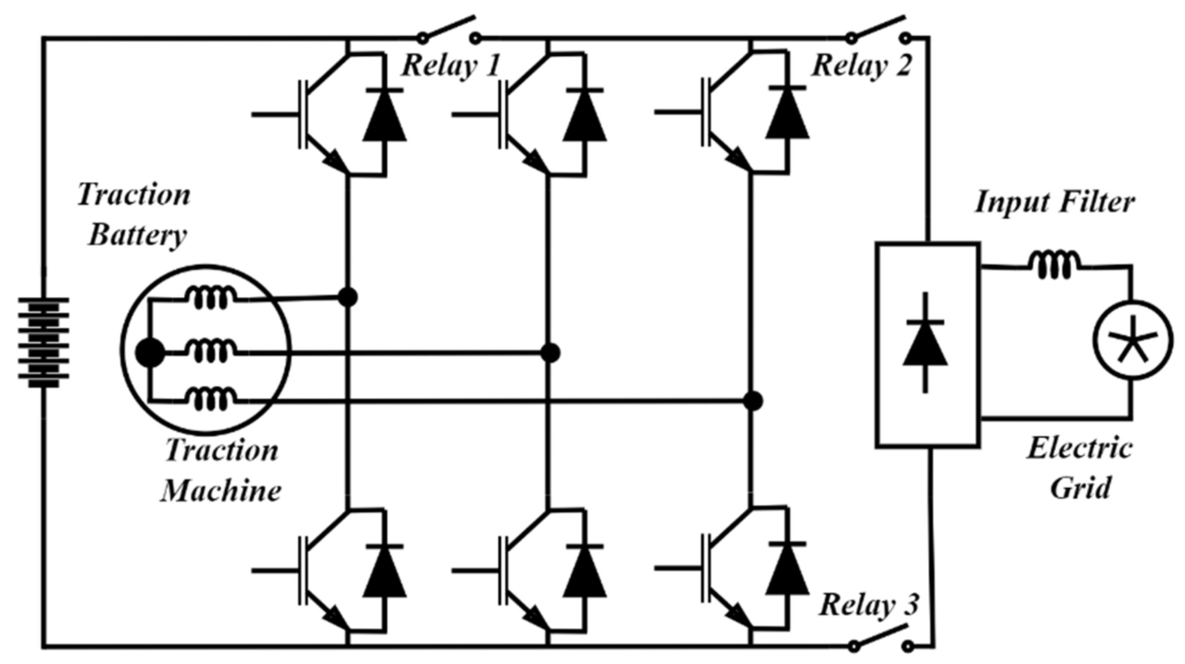
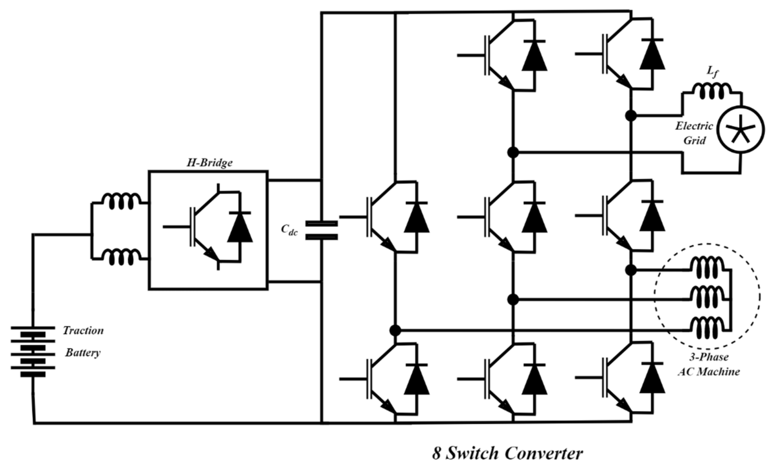
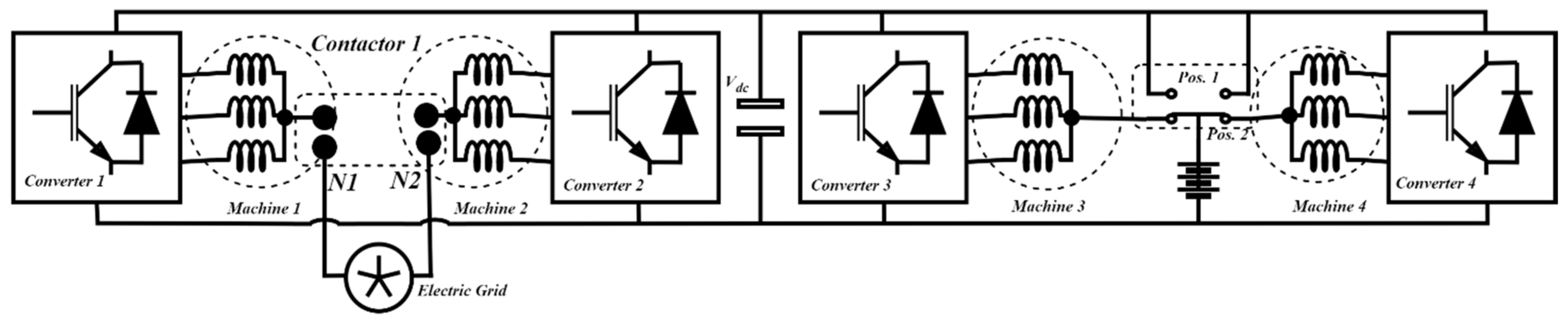
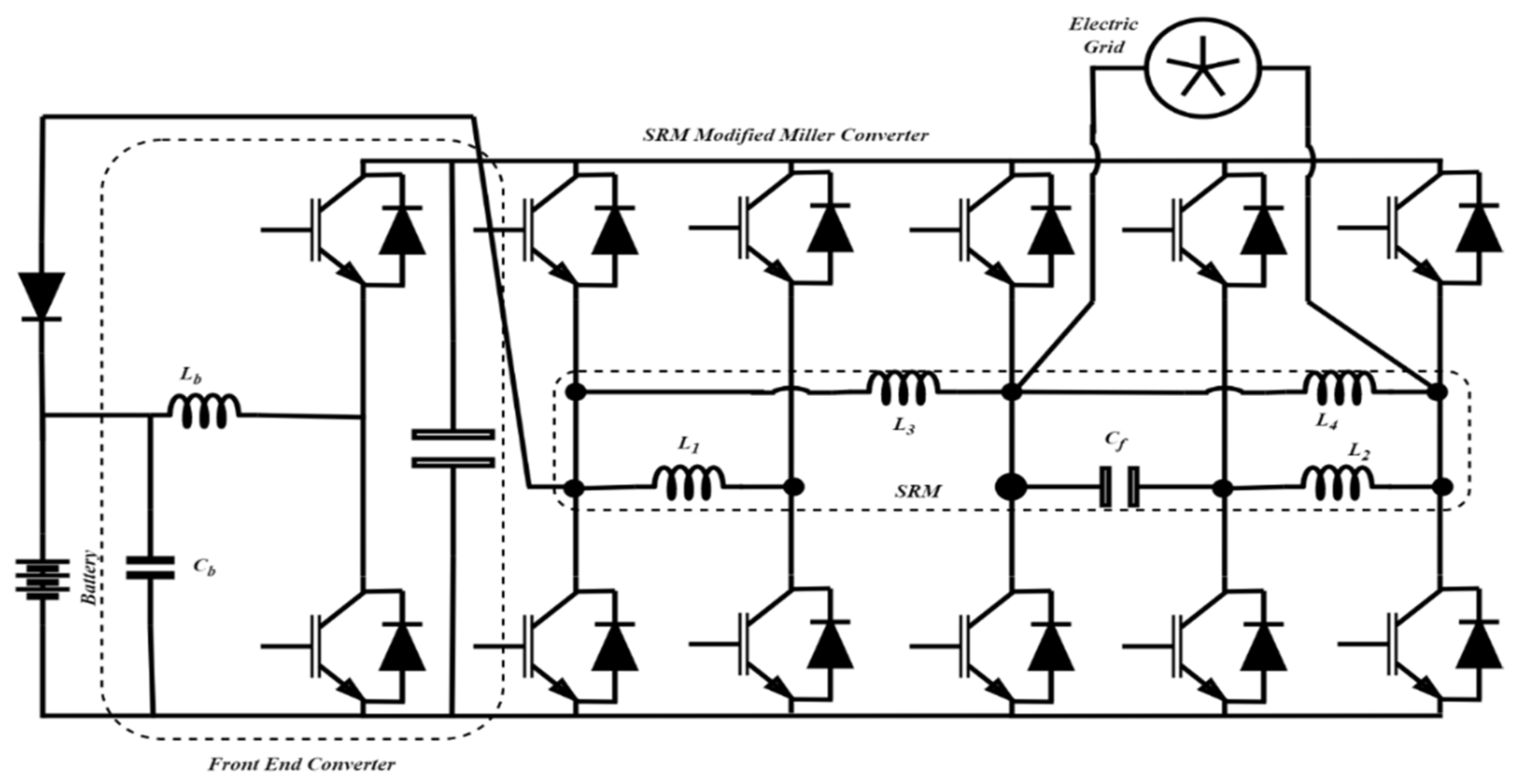
3. Integrated Chargers

The architecture of on-board chargers (OBCs) has been discussed in Section I. The OBC requires at least two power electronics converters for its two different power conversion stages. A separate power electronics converter provides power to the electric drive for propulsion. Separate power electronics increase the size, weight and cost of the overall EV powertrain system. One solution is the integrated onboard charger. Since both propulsion drive and the OBC are connected with the EV battery through power converters, and charging and propulsion are mostly mutually exclusive events, the charger converter can be modified for propulsion. This can reduce both the cost and size of the powertrain system. Thus, in an integrated OBC, the electrical components for charging/discharging and propulsion are shared. Integrated chargers can have single stage architecture or the conventional dual-stage architecture. Figure 3 below depicts both the architectures.
Integrated chargers can be classified as machine-integrated or converter-integrated. Machine-integrated chargers have the charging power injected into the machine windings that are utilizing them as the filter inductors. They can be either single stage or dual stage, as is depicted in Figure 3a, b. Converter integrated chargers are the ones where the charging current/power is injected through the traction converter and machine windings are left untouched. These types can also be classified into single stage or dual stage architectures. Figure 3 below depicts the different configurations of machine-integrated chargers.
In the single stage architecture, the electric grid is connected to the traction inverter via machine windings that act as an input filter; thus, no extra bulky filter is needed for the charger. The traction inverter acts as the AC to DC converter, and output is directly connected to the traction battery. In the two-stage architecture, an AC–DC rectifier is connected with the grid, and the power factor correction circuit is implemented first before the DC link is connected to the traction inverter, which essentially acts as a DC–DC converter during charging. During traction, a grid-side relay is opened, and the traction machine is powered via a traction inverter by the traction battery.
A three-phase integrated charger was proposed in [68], as is shown in Figure 4a. It has the two-stage architecture with an input three-phase AC–DC rectifying stage and a DC–DC stage utilising the inverter. The front-end converter is a traditional three switch AC–DC buck converter. During charging, the propulsion inverter acts as a DC–DC interleaved boost converter using the motor windings. The modulation index of the input stage and the duty cycle of the semiconductor devices in the propulsion converter are the two control parameters which govern the charging operation. A level 2 charger prototype was developed and an efficiency of 95.3% has been reported. The use of only three switches for the input converter and the reuse of the traction inverter reduces the size and increases the power density of the charger. Moreover, unlike most other topologies for integrated chargers, the proposed topology does not require modification in the motor construction. The main limitation of the topology is that it does not support bidirectional power flow, and the charging control is complex.
Same authors from [68] also proposed a similar structure for the single-phase charging operation investigated in [69], as is depicted in Figure 4b. The topology uses a diode bridge at the input. The positive terminal is connected with one of the phase terminals of the machine winding. The negative terminal of the diode bridge is connected with the negative terminal of the propulsion inverter/battery. During charging, the propulsion inverter, along with the machine windings, act as an interleaved boost converter and help with the PFC. The charging current flowing through the machine windings does not produce any torque. During propulsion, the diode bridge is reverse biased, and the inverter supplies power to the propulsion machine. This topology does not require any additional component and does not require modification of the propulsion machine. The size of the powertrain is reduced due to integration. A level 1 charger prototype was presented with a maximum power of 3 kW and a maximum efficiency of 93.1%. Detailed modelling of the permanent magnet synchronous motor/machine (PMSM) winding working as an inductor was also presented. The use of the bridge diode at the input end makes the charger suitable for unidirectional operation only.
In [70], the authors proposed another methodology to combine the propulsion converter with the charging converter as depicted in Figure 5. With the use of three relays, the proposed circuit works either in propulsion mode or in charging mode. Moreover, the DC–DC converter of the conventional charger is eliminated, as the propulsion inverter can be used as a buck/boost converter with the help of machine windings. It can be used either to charge a 48 V battery in buck mode, or a 192 V battery in boost mode. A control strategy was also presented to maintain unity power factor operation and reduce current harmonics. The motor stays at standstill during the charging period, although the charging current flows through the motor windings. A maximum efficiency of 88.3% was reported for the converter while working as a boost charger. The main limitation of the topology is that it is not a bi-directional topology, so it does not support vehicle to grid (V2G) operation. The efficiency is also on the lower band, and there is no galvanic isolation between the charger and the grid.
Three-phase machines in the integrated chargers tend to rotate during charging mode due to the developed torque, so they require either mechanical braking during charging, which makes them less efficient and wear-and-tear prone, or require complex control algorithms in order to have the resultant torque as zero. Six-phase machines, on the other hand, require no such mechanism. Two different sets of three phases can cancel out the torque produced during charging by the simple arrangement of windings. The authors in [71] proposed an integrated charger topology using a six-phase machine. It required a nine-switch-converter (NSC) to control the six-phase machine. The NSC has the advantage over two different conventional converters to supply and control the two different sets of three-phase voltages, as it only needs nine switches instead of twelve. It can also supply two different loads by controlling the switching frequency of the upper switches and lower switches differently. At the battery side, there is a boost converter. During the charging, the NSC acts as the conventional PWM converter, and the machine windings are utilized as the filter inductors. It can be noticed from Figure 6 that the sequence of the lower windings is reversed; this is to make sure that the total torque produced due to the battery charging current is zero. During traction operation, relay S3 is open, while S1 and S2 are closed. This disconnects the converter from the grid, and the NSC works as a drive inverter for the six-phase machine. The control algorithm is simple and can be applied without any complications. However, this system requires a specially modified six-phase machine, which can be costly.
In [72], the authors introduced a winding-midpoint current injection technique for charging an EV battery, as is shown in Figure 7. This is done to cancel out any torque produced due to the charging current. The topology utilizes three h-bridge converters, which also work as a boost PFC and a DC–DC buck/boost converter at the battery side. During charging, the three h-bridges act as active rectifiers, and machine windings are used as filter inductors. A current controller makes sure that the flux produced in each winding cancels each other, so there is no resultant torque during the charging mode. During traction mode, the three h-bridge converters act as single-phase drives for each winding. The topology requires access to the midpoints of the stator windings, which requires a specially designed machine for this charger. Moreover, the use of three h-bridges increases the number of switches, which means increased losses and decreased reliability of the integrated charger.
Similar to [71,73] also exploits the benefit of multi-phase machines for integrated charger operation, since they have an extra degree of control, which allows precise flux control in the traction machine during charging to produce zero torque. The authors presented the scheme for a five-phase machine, but it can be extended to any prime number of phases with at least one neutral point. For the proposed scheme, only two extra switches are needed apart from the traction drive, as is shown in Figure 8. During charging mode, the extra switches S1 and S2 are open, and the three-phase input is connected to the two neutral points and a phase outlet of the machine. The machine windings are utilized as filter inductors. The PFC operation is performed by a five-phase converter, which is used as a traction inverter during traction mode. A bidirectional DC–DC converter is required at the battery side if the battery voltage is lower than the grid voltage. During charging, a pulsating field is produced, due to the odd number of phases. This pulsating field is not enough to generate the starting torque of the machine. Current flowing in the five windings causes core losses in the machine and reduces the efficiency of the system. Moreover, to access the midpoints of the windings of the machine, a specially constructed machine is required.
A fast charger for level 2 charging was proposed in [74], as is shown in Figure 9. A surface mount permanent magnet (SPM) machine is used in this integrated charger. An off-board, three-phase transformer is used to isolate the grid from the charger. An additional contactor is used for the three phases. The secondary side of the transformer is connected to the three phases of the motor windings. During charging, the contactor connects the motor winding to the grid, and the windings act as an input filter. Power factor correction is done with a control strategy by controlling the duty cycle of the traction converter. During traction, the contactor connects the motor windings in star connection, and the traction inverter provides the required power. The proposed system supports up to 30 kW of charging with a maximum efficiency of 97%. The motor produces around 70 Newton meters of torque during charging when 80 A of charging current flows through the motor windings. This torque is not enough to rotate the machine, but some vibrations are produced. Thus, the system is prone to wear-and-tear. Moreover, if the system is to work in bidirectional mode, an additional DC–DC converter is required at the battery side in case the DC link voltage is lower than the peak line-to-line grid voltage.
The authors in [75] also presented a somewhat similar structure for the integrated charger as [72]. In [75], the authors modified the interior PMSM (IPMSM) machine’s rotor to have some damping bars, as is shown in Figure 10. This was to dampen any torque produced due to the charging currents. The proposed topology can work in bidirectional mode and, thus, can support both grid to vehicle (G2V) and vehicle to grid (V2G) operations. An off-board three phase transformer is required for ensuring isolation. The specially modified machine with the damping bars increases the cost. Also, the core losses increase due to the damping bars, which reduces the efficiency of the system.
Renault proposed an integrated charging scheme where the motor windings were utilized as an input filter, as is shown in Figure 11. The charger can be used for fast charging, as well as for level 1 or 2 charging [76]. The input rectifier stage was controllable, as unidirectional IGBTs were connected in series with the rectifying diodes. The duty cycle of the IGBTs governs the output current. The PFC operation can be performed either by the three-phase inverter stage or even by the input rectifier stage. A constant current–constant voltage (CC–CV) charging scheme is utilized, due to its simplicity and effectiveness. The rectified input current is connected to the neutral point of the star-connected motor windings. Therefore, the motor needs to be especially constructed according to the needs of the charger to provide access to the neutral point of the windings.
Hyundai patented an integrated charger for plug-in hybrid vehicles [49]. It utilizes two machines that can be used in both motoring and generating modes. The generating mode was used to recharge the battery during the braking period. It also facilitates the idle stop and go (ISG) feature, as the motor can be used to start and stop the engine during the start and stop of the vehicle to reduce the emissions. The proposed charger enables both level 1 and 2 charging. The two motors are connected to the grid using two relays, as is shown in Figure 12. The input AC is connected between the neutral points, and the PFC operation is done by the duty cycle control of the traction inverters, which work as active rectifiers in charging mode. A DC–DC converter is also connected at the battery end to regulate the DC link voltage. The access to the neutral point and the utilization of two motors are the main limitations, as they increase the cost and size of the charger.
The authors in [59] modified the traction inverter by adding two more switches, as is shown in Figure 13. The new topology can perform bidirectional, single-phase AC–DC operation, along with the traditional three-phase, bidirectional AC–DC operation. An interleaved DC–DC converter is also used at the battery end to control the DC link voltage for traction. It can act as a forward buck or reverse boost converter, depending on whether it is used for charging or traction. The proposed converter can also supply power back to the grid (V2G) by controlling the eight-switch converter as a single-phase DC to AC converter. The PFC operation is maintained using a control algorithm. Since motor windings are not used for the charging operation, there is no risk of torque production in the motor during charging. Also, no special construction for the traction machine is required. However, there is no galvanic isolation, and the added DC–DC converter, along with the two inductors, increases the charger weight and volume.
Most of the published topologies for integrated chargers are high voltage topologies. In order to apply the integrated charging theory for low voltage battery applications, the authors in [77] proposed a reconfigurable converter-based topology, as is shown in Figure 14. The topology works as a traditional two-stage OBC during the charging mode while all the contactors are in the normally open (NO) state. The traction inverter is reconfigured to work as a single-phase boost rectifier performing the PFC, and the third leg of the inverter is used for a DC–DC LLC converter. The LLC converter is utilized to provide the galvanic isolation. During charging, the two-phase windings of the motor are reconfigured to act in series, since the winding inductances are low, and the drive is basically designed to act for a low voltage machine. Thus, to ensure lower input current ripple during charging, the two windings are reconfigured to act in series to increase the inductance. The reconfiguration also ensures no torque is produced during the charging operation because of current in the windings. During propulsion, the system is reconfigured as a traditional three-phase voltage source inverter (VSI), i.e., all of the relays’ contacts are in the normally closed (NC) state. The use of 5 electromechanical relays in the topology increases the cost and reduces the system reliability.
In [78], an integrated charging strategy was proposed for four-wheel drive applications. The traction inverters for the four different wheels are the only power electronics needed in this charger. Only two additional relay contact sets are required apart from the traction inverters, as is shown in Figure 15. During charging, the contact set 1 connects the input supply between motors N1 and N2, while the contact set 2 is in position 2. The motor’s windings are utilized as the input current filter. A simple control strategy is applied. Since the input power is delivered through the neutral point of the windings, equal current flows in the windings and no torque are produced during the charging. The grid supply is disconnected during traction, and the contact set 2 position is moved to position 1. Custom designed motors are needed to get access to the neutral point of the windings.
The authors in [79] proposed the integrated low voltage charger for electric scooter applications. It used the traction inverter as the front-end rectifier and PFC during charging, while a bidirectional DC–DC converter was used at the battery end, as is shown in Figure 16. The proposed structure is capable of bidirectional power flow and thus can support V2G or V2H modes. During traction, the single-phase utility grid is disconnected by the relay contactor, and the traction inverter works as a traditional motor drive. Motor windings are utilized as the input filters during charging. The front-end of the charger is connected to the neutral point of the windings to make sure that there is no torque during charging. Moreover, in order to eliminate the 100 Hz power ripples introduced by the front-end rectifier, the DC–DC converter is tuned to provide sufficient gain at 100 Hz to eliminate the low frequency ripple. The charger needs access to the neutral point of the windings, which can make it costly, as special care needs to be taken while constructing the motor.
The benefits of a switched reluctance motor (SRM) were exploited in [80], (Figure 17) where a low speed SRM drive and integrated charger was proposed. A four-phase, eight pole SRM was utilized in the proposed application, which makes use of the modified Miller converter for the traction purpose. The modified Miller converter is made by two intelligent power modules (IPM) that essentially contain two three phase converters. While the five legs of the two IPMs are used as the modified Miller converter, the sixth leg is utilized to realise a DC–DC buck/boost converter. During charging, one of the phase windings acts as the input filter, while another winding acts as a DC–DC converter filter. The drive is suitable for low-speed applications, such as golf carts, commuter cars, electric scooters etc. The charging is only available at the level 1 charging level.
One of the major problems for any OBC is the existence of a low frequency ripple at the rectifier side which is then passed on to the battery through a charging current if a bulky DC link capacitor is not employed. One of the solutions is to utilize an auxiliary power filter (APF) circuit to absorb the lower frequency power, as is presented in [81]. The authors have utilized the motor windings as the input buffer filter during charging with an extra APF circuit to absorb the double line frequency power ripple. The traction inverter is utilized for PFC operation. A quasi-z-source DC–DC converter is utilized at the battery end to minimize the losses and control the power to and from the battery. The introduction of the extra APF adds to the cost, weight, and size of the charger. Figure 18 below depicts the circuit configuration.
One of the main problems of using the motor windings for charging is the developed stray torque. The authors of [82] used a split-phase motor design approach to avoid the development of torque during charging. During the charging operation, the three phase windings are split so that equal and opposite currents flow in all the phase windings, which leads to zero torque generation, as is shown in Figure 19. During traction, the windings are connected in series and they act as the normal three-phase machine driven by the traction converter. Construction of a split phase motor is the major issue for this topology, as it will require a specially constructed machine, which would increase the cost and effort. Moreover, the iron and core losses will also increase in the machine leading to add additional loss in efficiency. The charger is suitable for level 2 and level 1 charging and can also accommodate bidirectional power flow; thus, V2G is also supported. To provide extra protection, the authors advised using the external transformer for isolation.
An on-board integrated DC charger was proposed in [83]. The charger enables charging operation even during traction mode, which is suitable for vehicles with mobile charging sources, like solar PVs. The charger also provides fault protection. The charger can work in both buck and boost mode in both directions. However, it can only work with DC inputs. The front-end DC–DC converter is connected to the neutral of the three-phase winding during charging and injects the DC current, as is shown in Figure 20. Since the current responsible for torque generation is the iq current (q-axis charging current component), and the DC and iq currents are totally unrelated, there is no chance of torque generation during charging. The main limitation of the charger is that it only operates with DC supplies; thus, an off-board arrangement for AC to DC conversion is required if there is no solar PV. Thus, that would limit vehicle charging options, including at night time when there’s no sunlight.
In order to have zero torque during charging, a split-phase three-phase machine was proposed in [84]. The three phase windings of the machines are split into two equal parts, and the utility grid is connected to their mid-points, as is shown in Figure 21. This approach makes sure that the torque produced by one half-phase cancels out the torque produced by another half-phase. A dual inverter approach is considered in order to provide a path for the zero-sequence current. A modified new modulation strategy was also discussed, which minimizes the common-mode current during charging. The main limitation of the topology is that it requires special construction of the machine for splitting the phase-windings. Moreover, utilizing the dual inverter increases the cost and reduces the power density of the charger.
The simplest structure that could be found for the integrated chargers is that of utilizing the three-phase traction VSI as the AC–DC converter when charging and supplying the power to the battery [85,86]. The said technology has been present for a long time and has been applied in various arrangements to optimize its performance. It has the advantage of utilizing the lowest semiconductor devices and also can be controlled with zero torque during charging. In [85], an open neutral structure was proposed that could be supplied by a three-phase supply, as is depicted in Figure 22. For the three-phase supply, it required a special control strategy for torque control that essentially included d and q axis current control. In [86], a slightly improved configuration for the three-phase VSI was achieved via a single-pole-double-throw switch which made it possible to reconfigure the topology into a single-phase boost rectifier and a buck DC–DC converter during charging operation by utilizing the machine windings as smoothening inductors, as is depicted in Figure 23. The topology can be supplied by either three phase or single-phase supply. Apart from this, another approach is present in [81], where the authors reconfigured the three-phase machine windings into a split-six-phase machine during charging, which helps to cancel any torque that might cause the machine to vibrate or rotate.
Based on the literature survey done, a comparison table is drawn as depicted below in Table 4. Based on the comparison table, the main challenges with the machine-integrated OBCs are highlighted in the next section.

4. Challenges with Machine-Integrated OBCs

From Section 2, it is clear that integrated OBCs utilize motor windings in one way or another. Different methods utilizing the motor windings pose various challenges. Some of the major challenges for the integrated OBCs are highlighted below.
Most of the integrated chargers inject power directly into the windings of the machine to use them as a power buffer or filter. This rates the system at higher power ratings. This doesn’t pose a problem, as the machine and the converter are designed for high power traction. Nevertheless, this direct connection between the grid and the machine can cause problems, due to the lack of galvanic isolation. Leakage current due to no isolation in the integrated chargers can cause serious harm to the users, as well as to the control circuitry. A generalized modelling approach for the common mode current has been discussed in [87]. In order to avoid the common mode current, the main solution is to use an off-board transformer, as was proposed in [75]. But this makes the integrated chargers less useful, since they can’t be directly connected to the utility grid. Tesla has patented another solution in order to reduce the leakage current in the integrated system [88] by utilizing an interrupter circuit in case the leakage current exceeds the standard limit. Thus, having no electrical isolation with the utility grid is one of the major issues for the integrated chargers.
Another main issue with the integrated chargers is that, since they utilize the machine windings as filters, the charging current, as it flows through the windings, can produce torque in the machine and possibly give rise to vibrations or even rotation. To avoid this issue, many different solutions have been adopted in the literature. Multi-phase machines [71,73] have been utilized to use their windings in such a way that the electromagnetic torque produced by the different windings because of the charging current cancel out each other. Splitting the three-phase machine windings to access the middle point of each phase windings, as shown in [72], also cancels the electromagnetic torque produced. Apart from the multi-phase approach, the torque production can also be avoided by implementing a decoupled control algorithm that controls the individual d and q axis charging current components (id and iq) during charging operation. This does add to the complexity of the control system, and, in comparison to other solutions, it costs less.
Splitting the three-phase into six-phase, or the use of higher phase (>3) machines, can reduce the control complexity. But this approach requires access to the inaccessible points of the machine windings. The special construction of the machines for this purpose adds to the cost and design effort.
Using the same converter for traction, as well as for charging, increases the stress on the switches of the traction converter, which might decrease the long-term reliability of the semiconductor switches and capacitor. Since the number of power-cycles the converter has to go through increases, the mean time to failure (MTTF) decreases, which can reduce the lifetime of the traction inverter. A proper investigation into the decrease in reliability of the semiconductor switches in integrated chargers is needed to shed more light on this issue.

5. Conclusions and Future Aspects

A comprehensive review of the latest available literature on machine-integrated chargers is the key focus of this work. The main concept of the integrated charger is that the traction system and the charging converters are integrated since the two operations, i.e., EV battery charging and traction, are mutually exclusive events. The integration of the charging circuitry into the traction system is done by utilizing the machine windings as the input filters and by modifying the traction inverter through relays or switches. The first operation smooths the input current, and the second operation ensures a safe transition between the charging mode and the traction mode. Higher phase (>3) machines are used in several integrated chargers because of their higher torque density. Moreover, higher phases give more flexibility in designing the control system for the integrated charger. However, higher phase machines require modifications in the traction inverter. This paper presents different topologies that uss all the available options of integration, and the challenges for different topologies are also discussed.
In light of the paper, the future aspects of the integrated chargers involve working on the following problems:
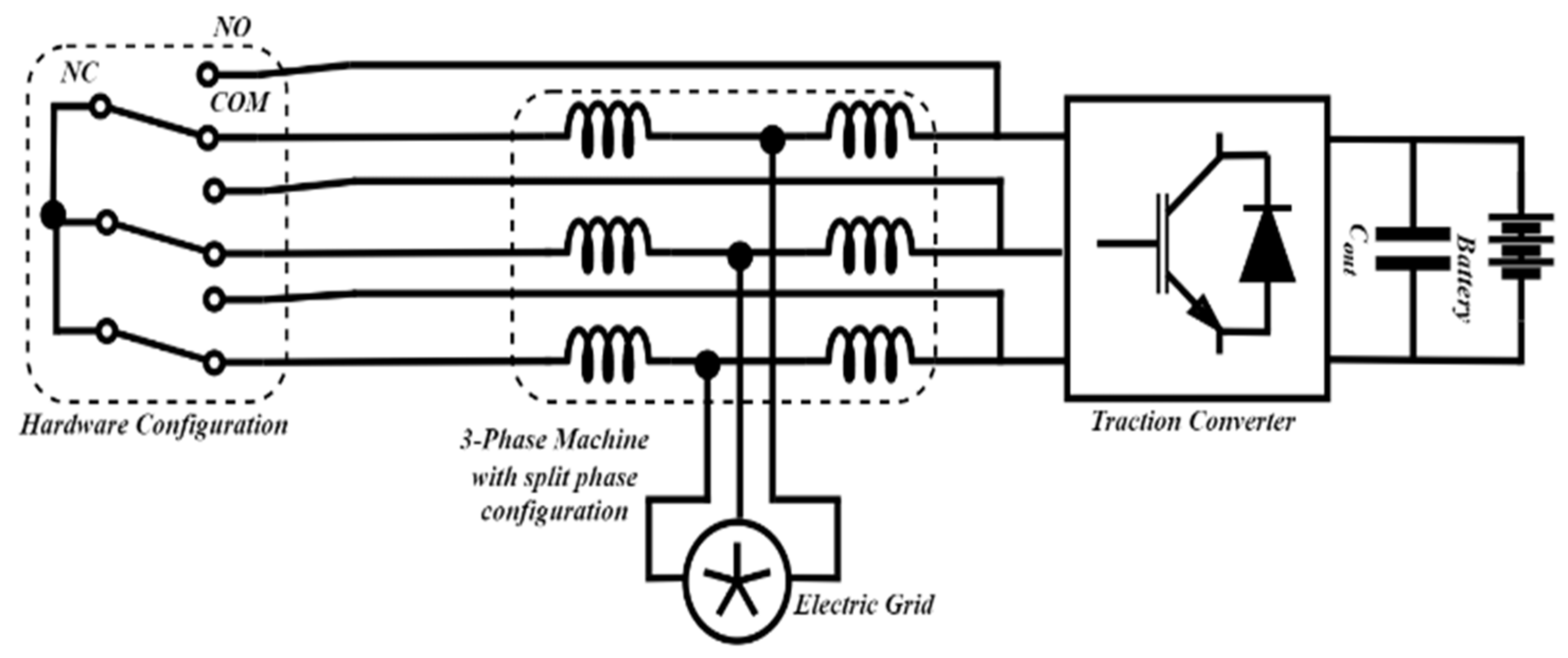
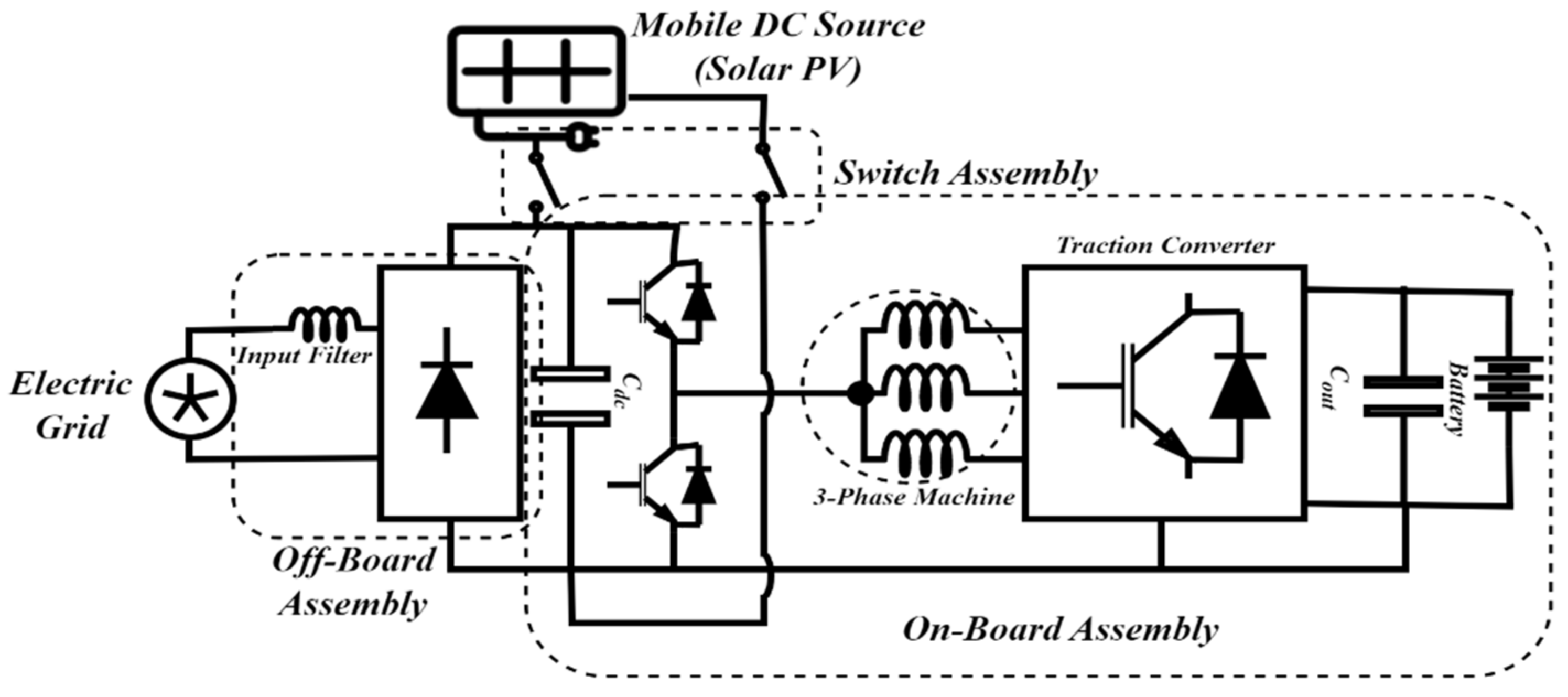
  • Most of the integrated chargers are non-isolated, and authors suggested using an off-board isolation transformer. This makes the whole concept of the OBC and integrated OBC less useful, as it will limit the use of OBCs to only be used in charging stations; thus, integrated chargers with on-board isolation need to be explored.
  • Since the same power electronics components will be utilized for traction and charging purposes, their utilization time is increased. This will have impact on their reliability. A study of the power electronics components with enhanced utilization rates is needed in order to determine the adverse effect on reliability.
  • The cost effectiveness of integrated chargers needs to be investigated when considering reliability and maintenance issues.
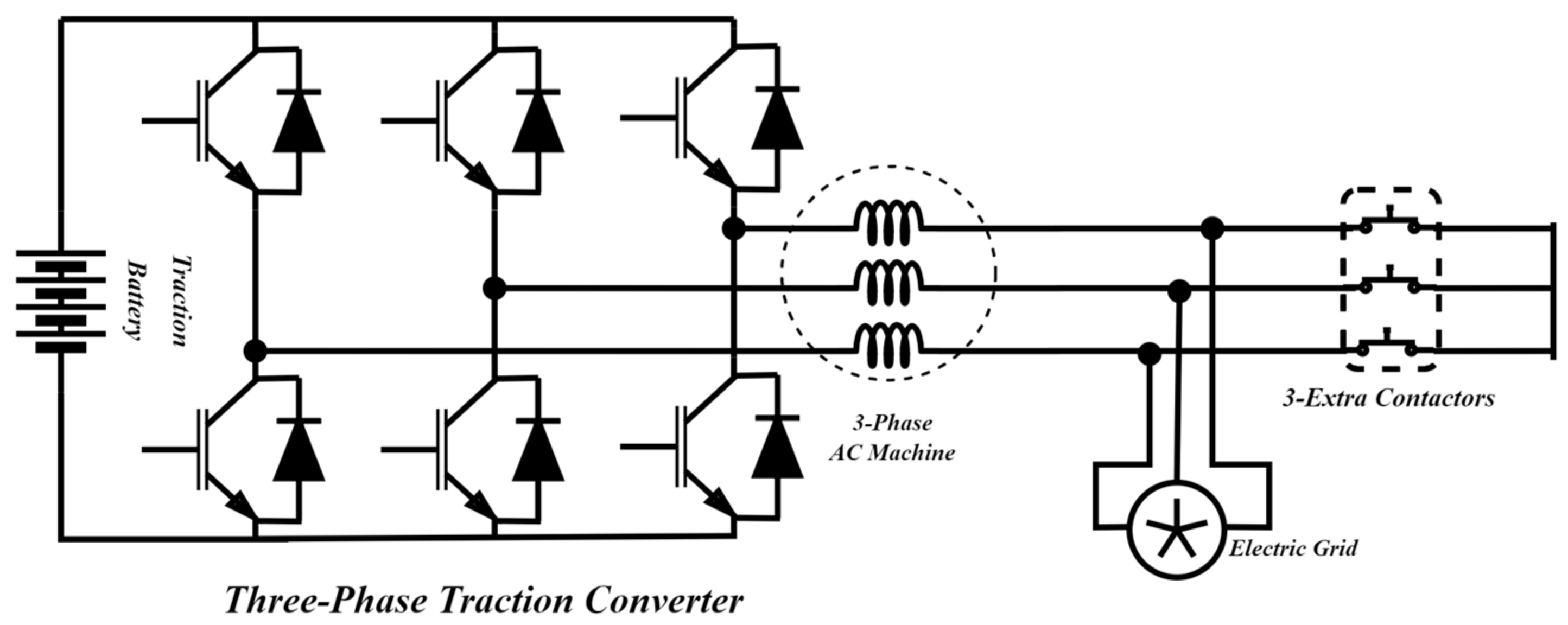
  • When utilizing the machine inductance as a filter, charging current through them may produce torque; higher-phase machines provide extra flexibility in terms of control and may present a good option to overcome this issue. Accordingly, their utilization needs to be investigated along with an effective comparison, in terms of their performance and cost, with the conventional three-phase machines.
  • The low-speed drives for applications like golf-carts utilize the switched reluctance motor. Integrated charger configuration for SRM-based drives needs to be investigated in order to reduce their cost and improve effectiveness.

Funding

This paper draws on research developed at the GKN Automotive Advance Research Centre.

Conflicts of Interest

The authors declare no conflict of interest.

References

  1. Element Energy Limited. Electric Cars: Calculating the Total Cost of Ownership for Consumers; Element Energy Limited: Cambridge, UK, 2021; p. 44. [Google Scholar]
  2. Habib, S.; Khan, M.M.; Abbas, F.; Sang, L.; Shahid, M.U.; Tang, H. A comprehensive study of implemented international standards, technical challenges, impacts and prospects for electric vehicles. IEEE Access 2018, 6, 13866–13890. [Google Scholar] [CrossRef]
  3. Ahmad, A.; Alam, M.S.; Chabaan, R. A comprehensive review of wireless charging technologies for electric vehicles. IEEE Trans. Transp. Electrif. 2017, 4, 38–63. [Google Scholar] [CrossRef]
  4. Trends and Developments in Electric Vehicle Markets—Global EV Outlook 2021—Analysis—IEA. Available online: https://www.iea.org/reports/global-ev-outlook-2021/trends-and-developments-in-electric-vehicle-markets (accessed on 17 September 2022).
  5. Chakraborty, S.; Vu, H.N.; Hasan, M.M.; Tran, D.D.; Baghdadi, M.E.; Hegazy, O. DC-DC converter topologies for electric vehicles, plug-in hybrid electric vehicles and fast charging stations: State of the art and future trends. Energies 2019, 12, 1569. [Google Scholar] [CrossRef] [Green Version]
  6. Global EV Market Outlook. Available online: https://www.eetasia.com/global-ev-market-outlook/ (accessed on 9 November 2022).
  7. Ashique, R.H.; Salam, Z.; Aziz, M.J.B.A.; Bhatti, A.R. Integrated photovoltaic-grid dc fast charging system for electric vehicle: A review of the architecture and control. Renew. Sustain. Energy Rev. 2017, 69, 1243–1257. [Google Scholar] [CrossRef]
  8. Ehsani, M.; Gao, Y.; Miller, J.M. Hybrid electric vehicles: Architecture and motor drives. Proc. IEEE 2007, 95, 719–728. [Google Scholar] [CrossRef]
  9. Benevieri, A.; Carbone, L.; Cosso, S.; Kumar, K.; Marchesoni, M.; Passalacqua, M.; Vaccaro, L. Series Architecture on Hybrid Electric Vehicles: A Review. Energies 2021, 14, 7672. [Google Scholar] [CrossRef]
  10. Sabri, M.F.M.; Danapalasingam, K.A.; Rahmat, M.F. A review on hybrid electric vehicles architecture and energy management strategies. Renew. Sustain. Energy Rev. 2016, 53, 1433–1442. [Google Scholar] [CrossRef]
  11. Singh, K.V.; Bansal, H.O.; Singh, D. A comprehensive review on hybrid electric vehicles: Architectures and components. J. Mod. Transp. 2019, 27, 77–107. [Google Scholar] [CrossRef] [Green Version]
  12. Yilmaz, M.; Krein, P.T. Review of battery charger topologies, charging power levels, and infrastructure for plug-in electric and hybrid vehicles. IEEE Trans. Power Electron. 2012, 28, 2151–2169. [Google Scholar] [CrossRef]
  13. Das, H.S.; Rahman, M.M.; Li, S.; Tan, C.W. Electric vehicles standards, charging infrastructure, and impact on grid integration: A technological review. Renew. Sustain. Energy Rev. 2020, 120, 109618. [Google Scholar] [CrossRef]
  14. Khalid, M.R.; Khan, I.A.; Hameed, S.; Asghar, M.S.J.; Ro, J.S. A comprehensive review on structural topologies, power levels, energy storage systems, and standards for electric vehicle charging stations and their impacts on grid. IEEE Access 2021, 9, 128069–128094. [Google Scholar] [CrossRef]
  15. Ruiz, V.; Pfrang, A.; Kriston, A.; Omar, N.; Van den Bossche, P.; Boon-Brett, L. A review of international abuse testing standards and regulations for lithium-ion batteries in electric and hybrid electric vehicles. Renew. Sustain. Energy Rev. 2018, 81, 1427–1452. [Google Scholar] [CrossRef]
  16. Sam, C.A.; Jegathesan, V. Bidirectional integrated on-board chargers for electric vehicles—A review. Sādhanā 2021, 46, 1–14. [Google Scholar] [CrossRef]
  17. Yan, X.; Li, J.; Zhang, B.; Jia, Z.; Tian, Y.; Zeng, H.; Lv, Z. Virtual synchronous motor based-control of a three-phase electric vehicle off-board charger for providing fast-charging service. Appl. Sci. 2018, 8, 856. [Google Scholar] [CrossRef] [Green Version]
  18. Yildirim, D.; Öztürk, S.; Çadirci, I.; Ermiş, M. All SiC PWM rectifier-based off-board ultrafast charger for heavy electric vehicles. IET Power Electron. 2020, 13, 483–494. [Google Scholar] [CrossRef]
  19. Solero, L. Nonconventional on-board charger for electric vehicle propulsion batteries. IEEE Trans. Veh. Technol. 2001, 50, 144–149. [Google Scholar] [CrossRef]
  20. Raj, J.S.S.; Sivaraman, P.; Prem, P.; Matheswaran, A. Wide Band Gap semiconductor material for electric vehicle charger. Mater. Today Proc. 2021, 45, 852–856. [Google Scholar]
  21. Abdelrahman, A.S.; Erdem, Z.; Attia, Y.; Youssef, M.Z. Wide bandgap devices in electric vehicle converters: A performance survey. Can. J. Electr. Comput. Eng. 2018, 41, 45–54. [Google Scholar] [CrossRef]
  22. Oh, C.Y.; Kim, D.H.; Woo, D.G.; Sung, W.Y.; Kim, Y.S.; Lee, B.K. A high-efficient non-isolated single-stage on-board battery charger for electric vehicles. IEEE Trans. Power Electron. 2013, 28, 5746–5757. [Google Scholar] [CrossRef]
  23. Monteiro, V.; Pinto, J.G.; Afonso, J.L. Operation modes for the electric vehicle in smart grids and smart homes: Present and proposed modes. IEEE Trans. Veh. Technol. 2015, 65, 1007–1020. [Google Scholar] [CrossRef] [Green Version]
  24. Tashakor, N.; Farjah, E.; Ghanbari, T. A bidirectional battery charger with modular integrated charge equalization circuit. IEEE Trans. Power Electron. 2016, 32, 2133–2145. [Google Scholar] [CrossRef]
  25. Gohari, H.S.; Abbaszadeh, K. A novel controllable bidirectional switching-capacitor based Buck-Boost charger for EVs. In Proceedings of the 2020 11th Power Electronics, Drive Systems, and Technologies Conference (PEDSTC 2020), Tehran, Iran, 4–6 February 2020; pp. 1–6. [Google Scholar]
  26. Liao, Y.H. A novel reduced switching loss bidirectional AC/DC converter PWM strategy with feedforward control for grid-tied microgrid systems. IEEE Trans. Power Electron. 2013, 29, 1500–1513. [Google Scholar] [CrossRef]
  27. Kwon, M.; Choi, S. An electrolytic capacitorless bidirectional EV charger for V2G and V2H applications. IEEE Trans. Power Electron. 2016, 32, 6792–6799. [Google Scholar] [CrossRef]
  28. Xue, L.; Shen, Z.; Boroyevich, D.; Mattavelli, P.; Diaz, D. Dual active bridge-based battery charger for plug-in hybrid electric vehicle with charging current containing low frequency ripple. IEEE Trans. Power Electron. 2015, 30, 7299–7307. [Google Scholar] [CrossRef] [Green Version]
  29. Lee, B.K.; Kim, J.P.; Kim, S.G.; Lee, J.Y. An isolated/bidirectional PWM resonant converter for V2G (H) EV on-board charger. IEEE Trans. Veh. Technol. 2017, 66, 7741–7750. [Google Scholar] [CrossRef]
  30. Texas Instruments Inc. Designing 6.6 kw Bidirectional hev/ev on-Board Charger with SiC and Embedded Technologies; Texas Instruments Inc.: Dallas, TX, USA, 2019. [Google Scholar]
  31. Tang, Y.; Ding, W.; Khaligh, A. A bridgeless totem-pole interleaved PFC converter for plug-in electric vehicles. In Proceedings of the 2016 IEEE Applied Power Electronics Conference and Exposition (APEC 2016), Long Beach, CA, USA, 20–24 March 2016; pp. 440–445. [Google Scholar]
  32. Liu, Z.; Li, B.; Lee, F.C.; Li, Q. High-efficiency high-density critical mode rectifier/inverter for WBG-device-based on-board charger. IEEE Trans. Ind. Electron. 2017, 64, 9114–9123. [Google Scholar] [CrossRef]
  33. Lee, J.Y.; Han, B.M. A bidirectional wireless power transfer EV charger using self-resonant PWM. IEEE Trans. Power Electron. 2014, 30, 1784–1787. [Google Scholar] [CrossRef]
  34. Wolfspeed. 6.6 kw High Power Density Bi-Directional EV on-Board Charger; Cree Power Applications; Wolfspeed: Durham, CA, USA, 2020. [Google Scholar]
  35. Bai, K. Applying Wide-Bandgap Devices to EV Battery Chargers. 2019. Available online: https://docplayer.net/164256141-Applying-wide-bandgap-devices-to-ev-battery-chargers.html (accessed on 13 November 2022).
  36. Li, H.; Bai, L.; Zhang, Z.; Wang, S.; Tang, J.; Ren, X.; Li, J. A.6.6 kW SiC bidirectional on-board charger. In Proceedings of the 2018 IEEE Applied Power Electronics Conference and Exposition (APEC 2018), San Antonio, TX, USA, 4–8 March 2018; pp. 1171–1178.
  37. Lai, J.S.; Zhang, L.; Zahid, Z.; Tseng, N.H.; Lee, C.S.; Lin, C.H. A high-efficiency 3.3-kW bidirectional on-board charger. In Proceedings of the 2015 IEEE 2nd International Future Energy Electronics Conference (IFEEC 2015), Taipei, Taiwan, 1–4 November 2015; pp. 1–5. [Google Scholar]
  38. Li, H.; Wang, S.; Zhang, Z.; Tang, J.; Ren, X.; Chen, Q. A SiC bidirectional LLC on-board charger. In Proceedings of the 2019 IEEE Applied Power Electronics Conference and Exposition (APEC 2019), Anaheim, CA, USA, 17–21 March 2019; pp. 3353–3360. [Google Scholar]
  39. Anderson, W.M.; Cambier, C.S. Integrated electric vehicle drive. SAE Spec. Publ. 1991, 862, 63–68. [Google Scholar]
  40. Chan, C.C. An overview of electric vehicle technology. Proc. IEEE 1993, 81, 1202–1213. [Google Scholar] [CrossRef]
  41. Lee, Y.J.; Khaligh, A.; Emadi, A. Advanced integrated bidirectional AC/DC and DC/DC converter for plug-in hybrid electric vehicles. IEEE Trans. Veh. Technol. 2009, 58, 3970–3980. [Google Scholar]
  42. Falvo, M.C.; Sbordone, D.; Bayram, I.S.; Devetsikiotis, M. EV charging stations and modes: International standards. In Proceedings of the 2014 International Symposium on Power Electronics, Electrical Drives, Automation and Motion, Ischia, Italy, 18–20 June 2014; pp. 1134–1139. [Google Scholar]
  43. Foley, A.M.; Winning, I.J.; Gallachóir, B.P.Ó. State-of-the-art in electric vehicle charging infrastructure. In Proceedings of the 2010 IEEE Vehicle Power and Propulsion Conference, Lille, France, 1–3 September 2010; pp. 1–6. [Google Scholar]
  44. Lu, M.H.; Jen, M.U. Safety design of electric vehicle charging equipment. World Electr. Veh. J. 2012, 5, 1017–1024. [Google Scholar] [CrossRef] [Green Version]
  45. International Electrotechnical Commission (IEC). IEC 60990:2016 RLV. In Methods of Measurement of Touch Current and Protective Conductor Current, 3rd ed.; International Electrotechnical Commission (IEC): Geneva, Switzerland, 2016; Available online: https://webstore.iec.ch/publication/24974 (accessed on 18 September 2022).
  46. Zhang, Y.; Perdikakis, W.; Cong, Y.; Li, X.; Elshaer, M.; Abdullah, Y.; Chen, C. Leakage current mitigation of non-isolated integrated chargers for electric vehicles. In Proceedings of the 2019 IEEE Energy Conversion Congress and Exposition (ECCE 2019), Baltimore, MD, USA, 29 September–3 October 2019; pp. 1195–1201. [Google Scholar]
  47. ISO 20200:2004; International Standard 61010-1 © Iec2001. ISO: Geneva, Switzerland, 2003.
  48. Hyundai Reveals IONIQ 5 EV for North America—Green Car Congress. Available online: https://www.greencarcongress.com/2021/05/20210525-ioniq5.html (accessed on 22 September 2022).
  49. Song, H.S.; Jang, K.Y. System for Recharging Plug-In Hybrid Vehicle by Controlling Pre-Charge of a DC link. U.S. Patent US8872473B2, 2010. [Google Scholar]
  50. Burress, T. Benchmarking Competitive Technologies, presentation at the 2013 and 2014 U.S. Department of Energy Hydrogen and Fuel Cells Program and Vehicle Technologies Program Annual Merit Review and Peer Evaluation Meeting, Washington D.C., June 2013 and 2015. Available online: https://www.energy.gov/sites/default/files/2014/03/f10/ape006_burress_2012_p.pdf (accessed on 13 November 2022).
  51. 2021 Nissan Leaf S Hatchback Features and Specs. Available online: https://www.caranddriver.com/nissan/leaf/specs/2021/nissan_leaf_nissan-leaf_2021 (accessed on 22 September 2022).
  52. Finnegworth, R.; Busey, C.; Lowald, K. Device for Charging a Battery of an Electrically Driven Motor Vehicle—CN111169300A. 2018. Available online: https://patents.google.com/patent/CN111169300A/en?oq=CN111169300A (accessed on 13 November 2022).
  53. 2021 Volkswagen ID 4 Pro S review: A Good EV Let Down by the Details. Available online: https://www.cnet.com/roadshow/reviews/2021-volkswagen-id-4-pro-s-rwd-review/ (accessed on 22 September 2022).
  54. BMWM. Information, Specifications; BMW X3. X3 xDrive30e; BMW: Munich, Germany, 2019; pp. 1–2. [Google Scholar]
  55. Weber, R.; Herzog, T. Charging Device for an Electric Energy Storage in a Motor Vehicle. European Patent Office EP2670624B1, 11 December 2013. [Google Scholar]
  56. Audi e-Tron Sportback 50 Quattro Specs. Available online: https://www.ultimatespecs.com/car-specs/Audi/119216/2021-Audi-e-tron-Sportback-50-quattro.html (accessed on 22 September 2022).
  57. Ruppert, D. Charging Device for a Motor Vehicle. German Patent Office DE102018203263A1, 6 March 2018. [Google Scholar]
  58. 2020 Renault Zoe-Specifications. Available online: https://www.evspecifications.com/en/model/d323ad (accessed on 22 September 2022).
  59. Hegazy, O.; Van Mierlo, J.; Lataire, P. Control and analysis of an integrated bidirectional DC/AC and DC/DC converters for plug-in hybrid electric vehicle applications. J. Power Electron. 2011, 11, 408–417. [Google Scholar] [CrossRef] [Green Version]
  60. Car Review-Mercedes-Benz EQA 250. Available online: https://www.leaseplan.com/en-be/get-inspired/car-review/mercedes-eqa-2021-review/ (accessed on 22 September 2022).
  61. Boehme, U.; Candir, A.; Haspel, A. On-Board Charger and Method for Charging a High-Voltage Battery of a High-Voltage on-Board Power Supply or a Low-Voltage Battery of a Low-Voltage On-Board Power Supply. Chinese Patent Office CN113874244A, 2019. [Google Scholar]
  62. Tesla Model Y Long Range Dual Motor. Available online: https://ev-database.org/car/1182/Tesla-Model-Y-Long-Range-Dual-Motor (accessed on 22 September 2022).
  63. Krauer, J.P. Bidirectional Polyphase Multimode Converter Including Boost and Buck Boost Mode. U.S. Patent US8638069B2, 2014. [Google Scholar]
  64. The Charging Process: Quick, Comfortable, Intelligent and Universal. Available online: https://newsroom.porsche.com/en/products/taycan/charging-18558.html (accessed on 22 September 2022).
  65. Gotz, S.; Reber, V. Modular Power Electronics Unit for Charging an Electrically Powered Vehicle. European Patent Office EP3333005B1, 2017. [Google Scholar]
  66. BAIC EC 180. Available online: https://wattev2buy.com/electric-vehicles/baic/baic-ec180-ev/ (accessed on 23 September 2022).
  67. Wang, H.; Yun, P.; Gao, Q.; Li, M. A Kind of Power-Driven System and Vehicle. Chinese Patent Office CN205818957U, 2016. [Google Scholar]
  68. Shi, C.; Khaligh, A. A two-stage three-phase integrated charger for electric vehicles with dual cascaded control strategy. IEEE J. Emerg. Sel. Top. Power Electron. 2018, 6, 898–909. [Google Scholar] [CrossRef]
  69. Shi, C.; Tang, Y.; Khaligh, A. A single-phase integrated onboard battery charger using propulsion system for plug-in electric vehicles. IEEE Trans. Veh. Technol. 2017, 66, 10899–10910. [Google Scholar] [CrossRef]
  70. Liu, T.H.; Chen, Y.; Yi, P.H.; Chen, J.L. Integrated battery charger with power factor correction for electric-propulsion systems. IET Electr. Power Appl. 2015, 9, 229–238. [Google Scholar] [CrossRef]
  71. Diab, M.S.; Elserougi, A.A.; Abdel-Khalik, A.S.; Massoud, A.M.; Ahmed, S. A nine-switch-converter-based integrated motor drive and battery charger system for EVs using symmetrical six-phase machines. IEEE Trans. Ind. Electron. 2016, 63, 5326–5335. [Google Scholar] [CrossRef]
  72. Lacroix, S.; Labouré, E.; Hilairet, M. An integrated fast battery charger for electric vehicle. In Proceedings of the 2010 IEEE Vehicle Power and Propulsion Conference (VPPC 2010); Lille, France, 1–3 September 2010; pp. 1–6. [Google Scholar]
  73. Subotic, I.; Bodo, N.; Levi, E. An EV drive-train with integrated fast charging capability. IEEE Trans. Power Electron. 2015, 31, 1461–1471. [Google Scholar] [CrossRef] [Green Version]
  74. Ali, S.Q.; Mascarella, D.; Joos, G.; Coulombe, T.; Cyr, J.M. Three phase high power integrated battery charger for plugin electric vehicles. In Proceedings of the 2015 IEEE Vehicle Power and Propulsion Conference (VPPC 2015), Montreal, QC, Canada, 19–22 October 2015; pp. 1–6. [Google Scholar]
  75. Lu, X.; Iyer, K.L.V.; Mukherjee, K.; Kar, N.C. Investigation of integrated charging and discharging incorporating interior permanent magnet machine with damper bars for electric vehicles. IEEE Trans. Energy Convers. 2015, 31, 260–269. [Google Scholar] [CrossRef]
  76. Loudot, S.; Briane, B.; Ploix, O.; Villeneuve, A. Fast Charging Device for an Electric Vehicle. U.S. Patent US2012/0286740 A1, 2013. [Google Scholar]
  77. Meher, S.R.; Banerjee, S.; Vankayalapati, B.T.; Singh, R.K. A reconfigurable on-board power converter for electric vehicle with reduced switch count. IEEE Trans. Veh. Technol. 2020, 69, 3760–3772. [Google Scholar] [CrossRef]
  78. Sul, S.K.; Lee, S.J. An integral battery charger for four-wheel drive electric vehicle. IEEE Trans. Ind. Appl. 1995, 31, 1096–1099. [Google Scholar] [CrossRef]
  79. Pellegrino, G.; Armando, E.; Guglielmi, P. An integral battery charger with power factor correction for electric scooter. IEEE Trans. Power Electron. 2009, 25, 751–759. [Google Scholar] [CrossRef] [Green Version]
  80. Chang, H.C.; Liaw, C.M. An integrated driving/charging switched reluctance motor drive using three-phase power module. IEEE Trans. Ind. Electron. 2010, 58, 1763–1775. [Google Scholar] [CrossRef]
  81. Na, T.; Yuan, X.; Tang, J.; Zhang, Q. A review of on-board integrated electric vehicles charger and a new single-phase integrated charger. CPSS Trans. Power Electron. Appl. 2019, 4, 288–298. [Google Scholar] [CrossRef]
  82. Haghbin, S.; Guillen, I.S. Integrated motor drive and non-isolated battery charger based on the torque cancelation in the motor. In Proceedings of the 2013 IEEE 10th International Conference on Power Electronics and Drive Systems (PEDS 2013), Kitakyushu, Japan, 22–25 April 2013; pp. 824–829. [Google Scholar]
  83. Viana, C.; Lehn, P.W. A drivetrain integrated DC fast charger with buck and boost functionality and simultaneous drive/charge capability. IEEE Trans. Transp. Electrif. 2019, 5, 903–911. [Google Scholar] [CrossRef]
  84. Viana, C.; Pathmanathan, M.; Lehn, P.W. Dual Inverter Integrated Three-Phase EV Charger Based on Split-Phase Machine. IEEE Trans. Power Electron. 2022, 37, 15175–15185. [Google Scholar] [CrossRef]
  85. Cocconi, A.G. Combined Motor Drive and Battery Recharge System. U.S. Patent 5,341,075, 23 August 1994. [Google Scholar]
  86. Serge, L.; Briane, B.; Ploix, O. Electric Motor Assembly Rechargeable from an Electrical Mains System, and Dedicated Connection Housing. U.S. Patent 9,035,608, 19 May 2015. [Google Scholar]
  87. Zhang, Y.; Yang, G.; He, X.; Elshaer, M.; Perdikakis, W.; Li, H.; Chen, C. Leakage current issue of non-isolated integrated chargers for electric vehicles. In Proceedings of the 2018 IEEE Energy Conversion Congress and Exposition (ECCE 2018), Portland, OR, USA, 23–27 September 2018; pp. 1221–1227. [Google Scholar]
  88. Krauer, J.P.; Kalayjian, N. Leakage Current Reduction in Combined Motor Drive Energy Storage Recharge System. U.S. Patent US20120019194A1, 14 August 2012. [Google Scholar]
Figure 1. Typical on-board charger configuration [12].
Energies 16 00129 g001
Figure 2. Broad classification of the available literature on EV chargers.
Energies 16 00129 g002
Figure 3. Two types of integrated chargers configurations: (a) machine-integrated single stage architecture; (b) machine-integrated two stage architecture; (c) inverter-integrated single stage architecture; (d) inverter-integrated two stage architecture.
Energies 16 00129 g003
Figure 4. Two types of integrated charger configurations: (a) three-phase integrated charger [68]; (b) single-phase integrated charger [69].
Energies 16 00129 g004
Figure 5. Single phase integrated charger using machine windings [70].
Energies 16 00129 g005
Figure 6. Integrated charger using six-phase machine [71].
Energies 16 00129 g006
Figure 7. Integrated charger for split-three phase machine proposed in [72].
Energies 16 00129 g007
Figure 8. Three-phase fast charger for polyphase machine proposed in [73].
Energies 16 00129 g008
Figure 9. Three-phase fast integrated charger proposed in [74].
Energies 16 00129 g009
Figure 10. Three-phase integrated charger with hardware reconfiguration proposed in [75].
Energies 16 00129 g010
Figure 11. Three-phase integrated fast charger by Renault [76].
Energies 16 00129 g011
Figure 12. Integrated charger by Hyundai [49].
Energies 16 00129 g012
Figure 13. Eight-switch inverter (ESI)-based integrated charger [59].
Energies 16 00129 g013
Figure 14. Reconfigurable VSI-based integrated charger [77].
Energies 16 00129 g014
Figure 15. A four-wheel drive-based integrated charger [78].
Energies 16 00129 g015
Figure 16. Single-phase integrated charger for electric scooter [79].
Energies 16 00129 g016
Figure 17. Integrated charger for an SRM-based EV [80].
Energies 16 00129 g017
Figure 18. Integrated charger with APF [81].
Energies 16 00129 g018
Figure 19. Split-phase integrated charger [82].
Energies 16 00129 g019
Figure 20. Integrated DC Charger with Solar PV as mobile DC source [83].
Energies 16 00129 g020
Figure 21. Split-phase integrated charger [84].
Energies 16 00129 g021
Figure 22. Three-phase integrated charger topology [85].
Energies 16 00129 g022
Figure 23. Reconfigurable VSI-based integrated charger [86].
Energies 16 00129 g023
Table 1. Charging levels and outlets.
Charger TypeCharger
Location
Voltage LevelPower LevelApprox. Charging Time (40kWh
Battery Capacity)
Charger Outlet
Connector
Europe/UKUSA
Level 1On-board
1 Phase
120 V ac1.4 kW (12 A)
1.9 kW (20 A)
11–36 h
4–11 h
SAEJ1772 T1SAEJ1772 T1
Level 2On-board
1 Phase/3 Phase
220 V ac/400 Vac4kW (17 A)
8 kW (32 A)
19. 2 kW (80 A)
2–6 h
1–4 h
2–3 h
IEC62196 T2SAEJ1772 T1
Level 3Off-board480 V ac (US)
400 V ac (EU)/
200-600 V dc
50 kW100 kW0.4–1 h
0.2–0.5 h
IEC 62196 T2/
CCS Combo 2
SAE J3068
CCS/Combo 1
Table 2. Standards to be followed by electric vehicles and their charging apparatuses.
Standard CodeDescription
Society for Automobile Engineers (SAE)
J1772Conductive charging standard. Defines the four main types of charging: AC level 1, AC level 2, DC level 1, and DC level 2
J1773Inductive charging standards combined with the level defined in the SAE J1772.
J2293All the protocols to be followed for transferring the energy from the utility to the EV battery system for the electric vehicle supple equipment (EVSE)
J2894This document essentially deals with laying down the power quality requirements for off-board or on-board chargers while interacting with the utility grid. According to it, the grid current total harmonic distortion (THD) should be less than 10%.
J2836/2847/2931This document is predominantly for off-board fast DC chargers which use the J1772 coupler. It lays out the foundation and communication standards via the SAE J1772 pilot line.
J2929This document defines the standards for battery propulsion systems.
J2910Primarily details the safety standards for heavy electric vehicles, such as electric trucks and buses.
J2344This document defines the safety standards of the electric vehicles.
J2464This is regarding the safety standards of the Rechargeable Energy Storage System (RESS).
National Fire Protection Association (NFPA)
NFPA 70Safety standards for the individuals who work near exposed energized electrical systems.
NFPA 70 EDeals with the safety standards for the individuals.
NFPA 70 BDeals with the design standards for electrical equipment in order to ensure their safe operation.
NEC 625/626This document defines the standards and the requirements for electric vehicle charging and supply equipment.
Institute for Electrical and Electronics Engineers (IEEE)
IEEE 519-2014This document defines the power quality standards for any interaction with the utility grid. The THD specified for the grid current is less than 8% for low and medium voltage.
IEEE P2030Standards for the interoperability of smart grid and charging stations.
IEEE 2030.1.1This document specifies the design standards for the DC fast charger and also specifies the communication standards for the controlling signals between the charging infrastructure and the CHAdeMO coupler interface.
IEEE 1901This document deals with the data rate for the overnight charging of the vehicles.
IEEE P2690These standards set the charging network management along with the vehicle authorization.
IEEE 1547These standards are essentially for any interaction between the grid and any distributed energy source.
IEEE P1809This document standardises the sustainable operation of the electric vehicle.
International Electrotechnical Commission (IEC)
IEC TC 64Standards for practicing safe practice with any electrical installation and electric shock protection.
IEC TC 69This document specifies the standards to be followed for the safe operation of any charging infrastructure.
IEC 1000-3-6This document defines the power quality standards for the interaction with the utility grid. According to it, the THD in the grid current should be less than 8% for medium and low voltages.
IEC TC 21This document deals with the battery management system.
International Organization of Standardizations (ISO)
ISO 15118-1 & 2These are the standards for the road vehicles for communication between the grid and the EVSE.
ISO 6469Standards for the safety of the Battery Management System
ISO 6469-1:2009Safety specifications for the RESS
ISO 6469-2:2009Safety specifications for electric vehicle operation and failure protection
ISO 6469-3:2009Safety specification for individuals against electric shock and hazard
Underwriters Laboratory (UL)
UL 2594/2251/2201/2231This document standardises the safety requirements for the EV OBC system, especially for the components operating at or lower than 600 V.
UL 225aSafety requirement for the design of electric couplers, plugs and receptacles.
UL 1741Standards for the any converter, inverter, or distributed energy system interacting with each other or with the grid. V2X communication.
Verband Deutscher Elektrotechniker (VDE)
DIN V VDE 0510-11Safety requirements for secondary battery installations and management systems.
DIN VDE 0126-1-1Safety standards for the common mode leakage current between the utility grid and any other connected electrical system.
Table 3. Commercially Available EVs and their Charger Specifications.
VehicleRef. No.YearCharger TypeOBC
Specifications
Battery
Capacity (kWh)
Max. Charging Power (kW)Charging Time
Hyundai Ioniq 5[48,49]2021
  • Integrated
  • Off-board
Non-Isolated, Bidirectional73
  • 10.9
  • 350
  • 6 h
  • 15–20 min
Nissan Leaf[50,51]2021
  • Separate
  • Off-board
Isolated, Unidirectional40
  • 6.6
  • 100
  • 4–5 h
  • 25 min
Volkswagen ID4[52,53]2021
  • Separate
  • Off-board
Isolated82
  • 11
  • 150
  • 7.5 h
  • 38 min
BMW X3[54,55]2021
  • Separate
  • Off-board
Non-Isolated43
  • 11
  • 150
  • 3 h
  • 25 min
Audi e-Tron[56,57]2021
  • Separate
  • Off-board
Isolated, Unidirectional71
  • 22
  • 120
  • 7 h
  • 28 min
Renault Zoe R135[58,59]2020
  • Integrated
  • Off-board
Non-isolated, Unidirectional55
  • 22
  • 50
  • 3 h
  • 1 h
Mercedes Benz EQA 250[60,61]2021
  • Separate
  • Off-board
Isolated, Bidirectional66
  • 11
  • 100
  • 5.8 h
  • 30 min
Tesla Model Y[62,63]2021
  • Separate
  • Off-board
Non-isolated, Bidirectional75
  • 22
  • 250
  • 4 h
  • 20–30 min
Porsche Turbo Taycan[64,65]2021
  • Separate
  • Off-B=board
Non-Isolated, Unidirectional93
  • 11
  • 50
  • 9 h
  • 2 h
BAIC EC180[66,67]2017SeparateNon-Isolated, Unidirectional226.63.5 h
Table 4. Comparison of the all the chargers presented in the literature. * Number of diodes, ** Number of active switches (IGBT/Mosfets).
Ref.Input PowerCharger Struct.Charger Arch.AC–DC StageDC–DC StagePower Flow Cap.Eff. (%)Nd *Ns **ProsCons
[67]3-PhaseMachine-integrated2-Stage3-switch buck rectifierInterleaved
boost using machine winding
Unidirectional95.3129
(i)
Zero torque generation
(ii)
No modified machine requirement
(iii)
Reduced active switch
(i)
Unidirectional
(ii)
Non-isolated
[68]1-PhaseTraction VSI-integrated2-StageDiode rectifierTraction VSI acting as buck/boostUnidirectional88.346
(i)
Zero torque generation
(ii)
Both buck and boost operation
(iii)
Reduced size due to low active switches count
(i)
Unidirectional
(ii)
Non-isolated
(iii)
Extra relays are required
[70]1-PhaseMachine-integrated2-StageDiode rectifierInterleaved boost using machine windingsUnidirectional93.146
(i)
Zero torque generation
(ii)
Low control complexity
(iii)
Reduced size
(iv)
No modified machine requirement
(i)
Unidirectional
(ii)
Non-isolated
[69]3-PhaseMachine-integrated2-Stage9-switch converter for 6-phase machineBidirectional DC–DC buck/boost converterBidirectional76.2011
(i)
Inherent zero torque generated
(ii)
Reduced size due to low active switch count
(iii)
Bidirectional power flow
(i)
Specially constructed machine
(ii)
Non-isolated
(iii)
Poor efficiency
[71]3-PhaseMachine-integrated2-Stage3 parallel h-bridgesBidirectional DC–DC buck/boost converterBidirectional--014
(i)
Inherent torque cancellation
(ii)
Bidirectional
(i)
Higher number of active switches
(ii)
Special construction of machine
(iii)
Non-isolated
[72]3-PhaseMachine-integrated1-Stage5-leg traction VSI for 5-phase machine--Bidirectional--010
(i)
Inherent torque cancellation
(ii)
Low number of active switches
(iii)
Bidirectional
(i)
2 extra relays are required
(ii)
Special construction of 5-phase machine
(iii)
Non-isolated
[73]3-PhaseMachine-integrated1-Stage3-phase traction VSI acting as rectifier--Bidirectional9706
(i)
Low number of active switches
(ii)
Bidirectional
(iii)
High efficiency
(i)
Vibrating torque in machine during charging
(ii)
Off-board isolation is required
(iii)
Extra contactors are required
[74]3-PhaseMachine-integrated2-Stage3-phase traction VSI acting as rectifierBidirectional DC–DC buck/boost converterBidirectional--08
(i)
Low number of active switches
(ii)
Bidirectional
(iii)
Zero toque generation
(i)
Non-isolated
(ii)
Special construction of machine with damping bars
(iii)
5 extra relays
[75]3-PhaseMachine-integrated2-StageCurrent source rectifier3-phase VSI acting as boost converterUnidirectional--612
(i)
Inherent zero torque
(ii)
Low control complexity
(ii)
(iii)
(i)
Non-isolated
(ii)
Specially constructed machine is required
(iii)
Unidirectional
[48]1/3-PhaseMachine-integrated2-Stage3-phase VSI acting as rectifierBidirectional DC–DC buck/boost conv.Bidirectional--014
(i)
Inherent torque cancellation
(ii)
Bidirectional
(i)
Non-isolated
(ii)
Specially constructed machine is required
(iii)
4 extra relays
[76]1-PhaseVSI-integrated2-Stage8-switch converterH-bridge acting as interleaved bidirectional DC–DC converterBidirectional--012
(i)
No torque generated
(ii)
No special construction of machine
(iii)
Bidirectional
(i)
Non-isolated
(ii)
Increased number of active switches
[59]1-PhaseMachine-integrated2-Stage3-phase VSI acting as rectifierLLCBidirectional97.626
(i)
Isolated
(ii)
Bidirectional
(iii)
No special construction of machine
(iv)
High efficiency
(i)
5 extra relays are required
(ii)
Low voltage charging
[77]1-PhaseMachine-integrated1-Stage3-phase VSI acting as rectifier--Bidirectional--024
(i)
Zero torque generated
(ii)
No special construction of machine
(iii)
Bidirectional
(i)
Non-isolated
(ii)
2 extra contactors are required
[78]1-PhaseMachine-integrated2-Stage3-phase VSI acting as rectifierBidirectional DC–DC buck/boost converterBidirectional87.508
(i)
Zero torque generated
(ii)
Lower number of active switches
(iii)
Bidirectional
(i)
Non-isolated
(ii)
Extra relay is required
(iii)
Specially constructed machine
[79]1-PhaseMachine-integrated2-StageModified miller converter for 4-phase SRMBidirectional DC–DC buck/boost converterBidirectional--112
(i)
Zero torque generated
(ii)
Bidirectional
(i)
Non-isolated
(ii)
Low voltage and low power charging
[80]1-PhaseVSI-integrated2-Stage3-phase VSI acting as rectifierQuasi z-source DC–DC converterBidirectional--07
(i)
APF circuit to remove low frequency harmonics
(ii)
No special construction of machine
(iii)
Bidirectional
(i)
Non-isolated
(ii)
Increased size due to APF
[81]3-PhaseMachine-integrated1-Stage3-phase VSI acting as rectifier--Bidirectional--06
(i)
Inherent zero torque generation
(ii)
Bidirectional
(iii)
Low number of active switches
(i)
3 extra relays are required
(ii)
Non-isolated
(iii)
Special construction of machine is required
[82]1-PhaseMachine-integrated2-StageDiode rectifier (off-board)3-phase VSI acting as DC–DC converterBidirectional--48
(i)
Can perform charging while mobile
(ii)
No special construction of machine
(iii)
Bidirectional
(i)
Off-board rectifier is needed
(ii)
Non-isolated
[83]3-PhaseMachine-integrated1-Stage3-phase VSI acting as rectifier--Bidirectional--012
(i)
No extra component is required
(ii)
Torque cancellation
(iii)
Bidirectional
(i)
Non-isolated
(ii)
Special construction of machine is required
[85]3-PhaseMachine-integrated1-Stage3-phase VSI acting as rectifier--Bidirectional--06
(i)
Bidirectional
(ii)
Zero torque operation
(iii)
No special construction of machine is required
(i)
3 extra contactors are required
(ii)
Non-isolated
[86]1/3-PhaseMachine-integrated1-stage3-phase VSI acting as rectifier--Bidirectional--06
(i)
Bidirectional
(ii)
Zero torque operation
(iii)
No special construction for machine
(i)
4 extra contactors are required
(ii)
Non-isolated
Disclaimer/Publisher’s Note: The statements, opinions and data contained in all publications are solely those of the individual author(s) and contributor(s) and not of MDPI and/or the editor(s). MDPI and/or the editor(s) disclaim responsibility for any injury to people or property resulting from any ideas, methods, instructions or products referred to in the content.

