Article

Effect of Non-Uniformity of Rotor Stagger Angle on the Stability of a Low-Speed Axial Compressor

Jiangsu Province Key Laboratory of Aerospace Power Systems, College of Energy and Power Engineering, Nanjing University of Aeronautics and Astronautics, Nanjing 210016, China
*
Author to whom correspondence should be addressed.
Energies 2022, 15(8), 2714; https://doi.org/10.3390/en15082714
Submission received: 22 March 2022 / Revised: 31 March 2022 / Accepted: 6 April 2022 / Published: 7 April 2022

Abstract

:
It is well known that variations in stagger angle between rotor blades affect compressor performance. In this paper, the stagger angle of blade No. 8 is increased or decreased by six degrees for non-uniformity, and the influence of rotor non-uniformity caused by the change in only one blade stagger angle on the performance and stability of the compressor is investigated. The experimental results show that whether the local rotor stagger angle increases or decreases, the compressor stability will deteriorate. If the stagger angle of blade No. 8 is reduced by six degrees, the flow coefficient at the stall point increases by 8.5%. If the stagger angle of blade No. 8 is increased by six degrees, the flow coefficient at the stall point increases by 1.5%. The reason for the deterioration of compressor stability caused by the local non-uniform rotor stagger angle is explored. When the stagger angle of rotor blade No. 8 deviates from the designed state, the load of blade No. 8 and the surrounding blades will change. The load on rotor blade No. 8 increases when the stagger angle decreases. In the near-stall condition, blade No. 8 becomes the “dangerous blade” that triggers the stall. As the stagger angle of rotor blade No. 8 increases, the load on blade No. 8 decreases. However, the load on blade No. 9 increases due to flow redistribution and blade No. 9 becomes a “dangerous blade” that triggers stall. The “dangerous blade” caused by the non-uniformity of stagger angle is the direct reason for the advance of the compressor rotating stall.

1. Introduction

The blade disk of an aviation compressor is usually designed as a rotating periodic structure. However, the symmetry is usually destroyed due to uncertain factors such as manufacturing tolerances and variation, aging, damage, and maintenance of the material, which is called blade mistuning [1]. Blade mistuning usually has adverse effects, such as performance degradation [2], aerodynamic excitation [3], and buzzer noise [4,5,6]. Previous studies show that the non-uniformity between blades can improve flutter stability [7,8,9,10]. However, there are few studies on the influence of blade non-uniformity on compressor stability. Day [11] pointed out in the article “Stall, Surge, and 75 Years of Research” that it is necessary to explore the influence of non-uniformity caused by geometric deviations in the compressor stability margin.
The parameters that lead to non-uniformity between blades include stagger angle, leading and trailing edge shape, thickness, length, and radian of the blade. Through experiments and numerical simulation, Reitz et al. [12] concluded that the stagger angle has a great impact on the aerodynamic performance of the rotor, and the reduction in the stagger angle may increase the work and the pressure coefficient. The rotor stagger angle directly affects the incidence angle, which determines the load of the rotor and plays an important role in the stall inception process [13,14]. Thus, it is valuable to study the influence of the variation in the stagger angle between rotors on the performance and stability of the real compressor.
Previous studies have focused on the effect of non-axisymmetric rotor stagger angle on compressor performance. The numerical simulation of a transonic fan by Venkatesh [15] showed that the change in passage area caused by a non-uniform stagger angle will lead to movement in the shock wave, which affects the fan’s efficiency and pressure ratio. Zheng [16] conducted many calculations on a three-stage high-pressure compressor with the commercial software NUMECA and pointed out that the performance of sinusoidal distribution of rotor stagger angle is better than that of other distributions. In order to quickly analyze the impact of uneven stagger angle on compressor performance, some new calculation methods have been developed [17,18]. Phan [17] et al. developed a computational model for analyzing the influence of a non-uniform stagger angle based on the principle of multi-scale method within the framework of a commercial solver (CFX). Wang [18] developed a spectral method that projected flow disturbances due to geometrical inhomogeneity in Fourier space. Only one channel is needed to calculate the flow disturbances corresponding to a certain number of geometrical changes, and the calculation cost is significantly reduced. The relationship between asymmetric stagger angle and compressor performance has been studied and some efficient performance calculation methods have been established, which is very helpful for us to study the phenomenon of non-uniform rotor stagger angle in compressors. However, there is little research on the influence of non-uniformity of rotor stagger angle on compressor stability.
Experiments carried out by Nishioka [19] on a single low-speed axial flow compressor showed that reducing the stagger angle of all rotor blades leads to a stall advance. Yong [20] conducted experiments on a low-speed research compressor (LSRC) of the General Electric Aircraft Engine Company to investigate the effects of flow coefficient, stagger angle, and blade tip clearance on vortex flow at the blade tip, which showed that the increase in the stagger angle weakens the vortex at the tip of the blade and moves it slightly downstream, which, according to Hoying’s theory [21], allows the compressor to work stably at a smaller flow coefficient. However, it is not clear how the compressor stability would change when the rotor stagger angle is non-uniform. As suggested by Day [11], new work needs to be conducted to study the influence of non-uniform stagger angle on compressor stability.
The relationship between rotor stagger angle and compressor stability has been shown to be monotonic—that is, compressors with small stagger angle settings have lower stability, and compressors with large stagger angle settings have higher stability. However, the stability of the compressor is not clear when there is an increase in the stagger angle of a rotor blade in the compressor. To investigate this, experiments on a low-speed axial flow compressor with a non-uniform stagger angle were carried out in this paper.
This paper is divided into three main parts. The first part is a detailed introduction that describes the non-uniform layout of the stagger angle and the experimental method. The second part shows the results and discussion under different stagger angle settings. The third part is a summary, which presents some conclusions based on the work of this study.

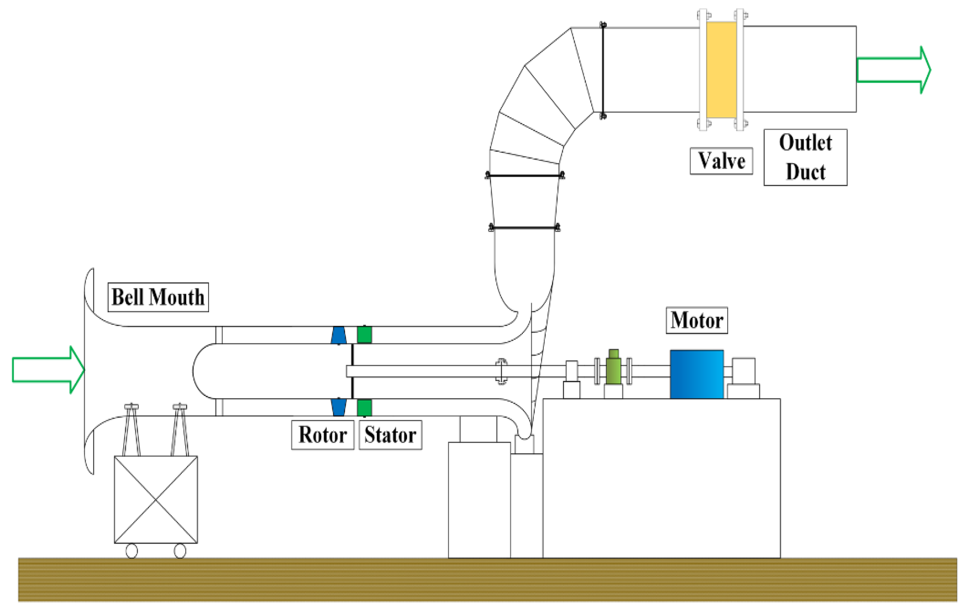
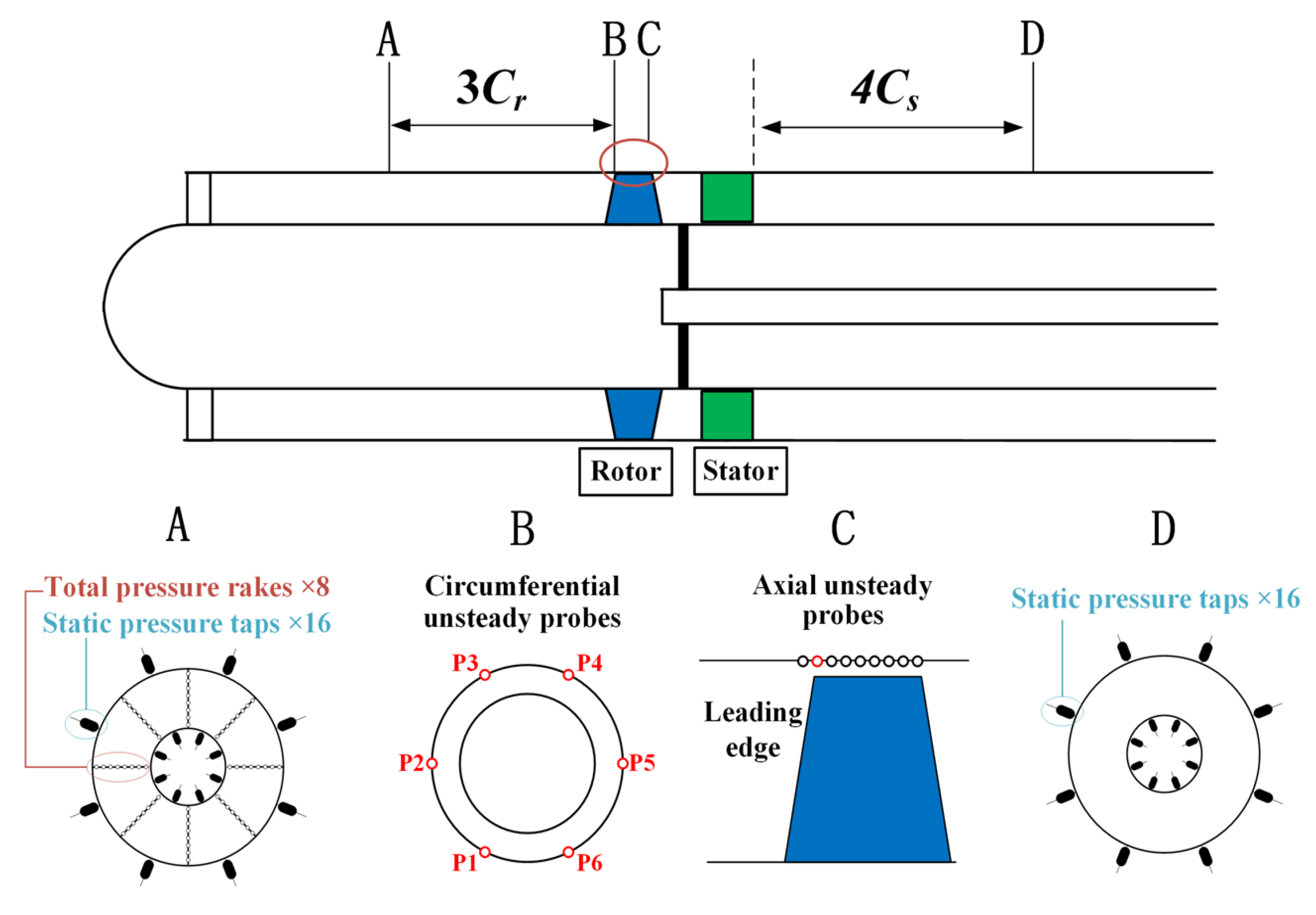
2. Experiment Methods

The work in this paper was carried out on a low-speed axial flow compressor designed on the basis of the free vortex principle under uniform axial inlet conditions. A sketch of the experimental rig is shown in Figure 1, which consists of a bell mouth, single-stage compressor, and outlet duck. The single-stage compressor is driven by an electric motor with an adjustable motor speed. The operating point of the compressor is controlled by adjusting the valve in the outlet section. The key parameters of the compressor are shown in Table 1.
The measurement methods in the experiment are divided into steady measurement and unsteady measurement. The measurement layout is shown in Figure 2. Steady measurement consists of static pressure probes and total pressure rakes at station A and station D. Eight total pressure rakes at station A and 16 static pressure probes at station D are used to calculate the total static pressure rise coefficient. The flow coefficient is calculated according to the 16 static pressure probes at station A, atmospheric temperature, and pressure. The uncertainty of the sensor used for steady measurements is 0.05% of its measurement range, which is 1 PSI. The uncertainties of the total static pressure rise coefficient and the flow coefficient are calculated from the error propagation equation as 0.8% and 0.4%, respectively. Unsteady measurement is used to record fluctuations in casing static pressure, which is accomplished by the MIC-062 high-frequency differential pressure sensor from Kulite Semiconductor Products. The high-frequency sensor provides a range of 1 PSI, a response rate of 512 kHz, and a sensitivity of 30.8 mV/PSI. The unsteady probes are placed in circumferential and axial configurations, respectively, as shown in Figure 2. The circumferential configuration includes six probes that are evenly placed along the annular at a plane of the rotor leading edge, whose positions are recorded as P1–P6, respectively. At circumferential position P5, nine axial probes are evenly distributed from the plane of 14% chord upstream of the leading edge to the trailing edge. The sampling frequency of the unsteady probe is 50,000 Hz, ensuring that there are 45 sampling points in each blade passage.
Generally, there are two ways of defining the blade stagger angle: (1) the angle between the chord and the axial direction, and (2) the angle between the chord and the tangential direction. The stagger angle used in this paper is defined as the angle between the chord and the axial direction of the blade, as shown in Figure 3. The change in stagger angle is achieved by rotating the blade around the mounting axis. When the blade is rotated clockwise at the designed stagger angle position, the stagger angle decreases and the stagger angle increases. There are 44 rotor blades in the experimental compressor, and they are numbered in a counterclockwise direction, noted as Blade No. 1–Blade No. 44. Three stagger angle layouts are studied in this paper, as shown in Figure 4. Case 0 is the design setting, and the stagger angle of blade No. 8 in Case 1 and Case 2 is reduced and increased by six degrees, respectively. Theoretically, the stagger angles of the 44 rotor blades in Case 0 should be identical to ensure uniformity, but in practice, errors are unavoidable. The variation in stagger angle between each blade in Case 0 is within 1 degree. The stagger angle of blade No. 8 in Case 1 and Case 2 changes by six degrees, which is enough to reflect the influence of non-uniform stagger angle. A Hall sensor is fitted at position P1 on the leading edge of the rotor (section B in Figure 2) and a magnet is mounted at the top of blade No. 15, as shown in Figure 5. Each time blade No. 15 passes position P1, a pulse signal is triggered by the Hall sensor. This phase-locked technique can be used to identify the unsteady signal corresponding to each blade.

3. Results and Discussion

In this section, the effect of non-uniformity in the rotor stagger angle on performance is first discussed; then, the variation in the tip flow field and blade loading is analyzed; and finally, the effect of non-uniformity of the stagger angle on the stall inception process is discussed.

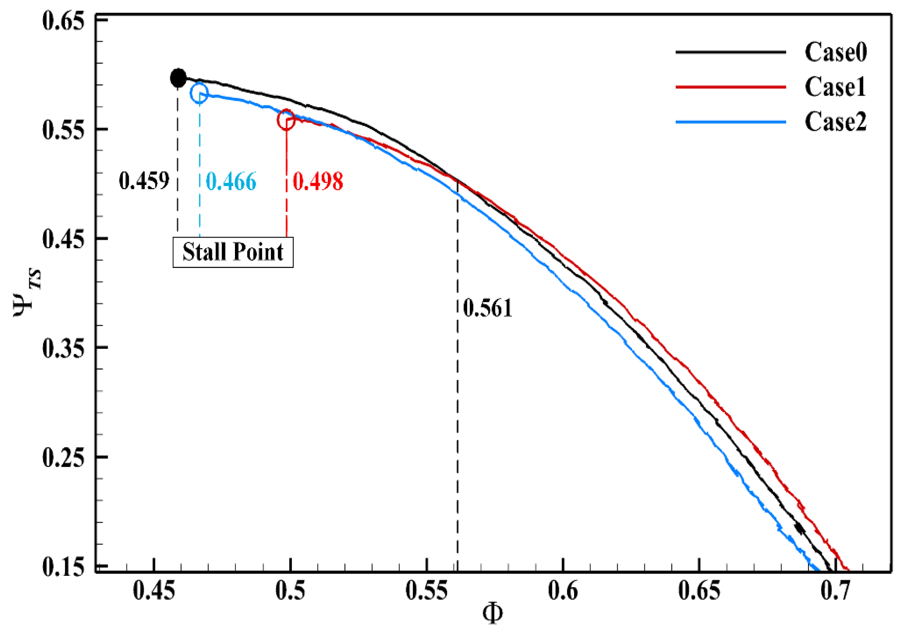
3.1. Performance Map

The performance of the compressor is evaluated by the total static pressure rise coefficient versus flow coefficient. The total static pressure rise coefficient Ψ T S and the flow coefficient Φ are defined as shown in Equations (1) and (2), respectively. P t , i n l e t is the inlet total pressure, P s , o u t l e t is the outlet static pressure, ρ is the inlet airflow density, U m is the circumferential velocity at the rotor mid-diameter, and V z is the inlet axial velocity.
Ψ T S = P s , o u t l e t P t , i n l e t 0.5 ρ U m 2
Φ = V z U m
Figure 6 illustrates the total static pressure rise characteristics for the three stagger angle settings. For Case 0, the compressor is stalled at the flow coefficient of 0.459. The stall flow coefficients of Case 1 and Case 2 are 0.498 and 0.466 respectively, which are increased by 8.5% and 1.5%, respectively, compared with Case 0. This means that, whether the stagger angle of blade No. 8 is reduced or increased, local non-uniformity in the stagger angle will deteriorate the compressor stability. Although the stagger angle of blade No. 8 is changed by six degrees in both Case 1 and Case 2, the degradation of the compressor stability is more severe when reduced by six degrees. Figure 6 also reflects the effect of non-uniformity on the compressor performance. When the flow coefficient is greater than 0.561, the total static pressure rise coefficient for Case 1 is greater than that of Case 0, and when the flow coefficient is less than 0.561, the total static pressure rise coefficient for Case 1 is less than that of Case 0. For Case 2, the total static pressure rise coefficient is always less than that of Case 0. The reasons that the uneven settings of the stagger angle deteriorate the stability and affect the performance of the compressor will be discussed in the following subsection.

3.2. Unsteady Measurement Results at Stable Operating Points

The unsteady probe at the leading edge of the rotor is used to measure the static pressure signal on the compressor casing when the compressor is operating. Since the pressure surface and suction surface of the blade alternately pass through the probe, the pressure signal measured by the unsteady probe periodically fluctuates over time, as shown in Figure 7. The pressure differences between the peak (A) and trough (B) in one period of the pressure signal, ∆P, are tabulated as blade load.
At a flow coefficient Φ of 0.580, the ensemble average of the pressure signals at the leading edge of rotor is carried out. The ensemble average is defined as Equation (3), where P i is the relative pressure at each sampling point and N is the number of rotor revolutions. In each case, pressure signals of 50 revolutions are used for ensemble averaging, and Figure 8 shows the ensemble average pressure signal of blades No. 1–No. 11. As can be seen in Figure 8, the change in the stagger angle of blade No. 8 not only affects its own pressure trajectory but also the pressure trajectory of its surrounding blades; for example, the pressure trajectory of blades No. 9 and No. 10 in Case 1 and Case 2 deviates from Case 0.
P i E n s e m b l e = k = 1 N P i k N
In order to quantitatively describe the effect of non-uniform stagger angle on blade load, the dimensionless blade load Δ P n o r n is defined, as shown in Equation (4). In Equation (4), Δ P n o r n is the dimensionless load of blade No. n, Δ P n is the load of blade No. n in Case 1 (or Case2), and Δ P Case   0 n is the load of blade No. n in Case 0. The dimensionless blade load Δ P n o r n reflects the change in the load of blade No. n in Case 1 (Case 2) compared with that in Case 0. If Δ P n o r n is greater than 0, it means that the load of blade No. n in Case 1 (Case 2) is increased compared with that in Case 0, and vice versa.
Δ P n o r n = Δ P n Δ P Case   0 n Δ P Case   0 n
Figure 9 illustrates the dimensionless load   Δ P n o r n and the change in stagger angle ∆β for Case 1. Compared with Case 0, the load of blade No. 8 in Case 1 significantly increases because the incidence increases. As can be seen in Figure 9, the reduction in the stagger angle of blade No. 8 also has an effect on the surrounding blades. To be specific, the loads of blades No. 5–No. 7 and No. 10–No. 12 are reduced, with the greatest reduction of about 15% occurring for blade No. 10. Loads of other blades are all comparable to those in Case 0. The increase in the load on blade No. 8 at a flow coefficient of 0.580 in Case 1 explains why the total static pressure rise coefficient in Case 1 is greater than that in Case 0 when the flow coefficient is greater than 0.561.
Figure 10 illustrates the dimensionless load   Δ P n o r n and the change in stagger angle ∆β in Case 2. For Case 2, the stagger angle of blade No. 8 is increased by six degrees. The incidence of blade No. 8 is reduced and therefore its blade load is significantly reduced compared to Case 0 by approximately 90%. The non-uniformity of the stagger angle in Case 2 affects the load on the blades around blade No. 8, as evidenced by a slight reduction in the load on blades No. 6–No. 7 and an increase in the load on blades No. 9–No. 13. Blade No. 9, which is mostly affected by the non-uniformity, is loaded by approximately 40% and becomes the blade with the largest load. The total static pressure rise coefficient for Case 2 in Figure 6 is less than that of Case 0 for all flow ranges, which is mainly due to the significantly reduced load on blade No. 8.
At a flow coefficient of 0.580, the ensemble average of the static pressure signals is performed for each axial high-frequency sensor. The static pressure is then normalized and the normalized static pressure is calculated as shown in Equation (5), where ( p s p 0 ) is the pressure measured by the Kulite sensor. A coordinate matrix is created with the axial position of the sensors and the order of the sampling points. The normalized static pressure corresponding to all elements of the coordinate matrix is used to plot the static pressure contour over the rotor tip. Figure 11 presents the normalized phase-locked ensemble-averaged static pressures (𝐶𝑝) over the rotor tip at a flow coefficient Φ of 0.580. The trajectory of the tip leakage flow is usually estimated by the static pressure troughs, which are shown as white curves with arrows in Figure 11. The generation of stall inception disturbances is related to the stability of the tip leakage vortex, which moves towards the leading edge of the blade when a stall inception signal appears [20]. For Case 0, the tip leakage vortex is deep in the blade passage and the trajectory of the tip leakage vortex is almost uniform for each blade. However, the tip leakage vortex of blade No. 8 in Case 1 is significantly different from that of Case 0, showing a feature close to the leading edge of the blade. The tip leakage vortex trajectory of all blades in Case 1 except blade No. 8 still penetrates deep into the blade passage. The tip leakage vortex of blade No. 9 in Case 2 is closer to the leading edge of the blade than the other blades, and the tip leakage vortex of blade No. 7 is closer to the trailing edge.
C p = p s p 0 0.5 ρ U m 2
With further throttling, the compressor comes to near-stall conditions, and the static pressure contours over the rotor tip at the near-stall condition for the three stagger angle settings are shown in Figure 12. In the near-stall condition, the flow coefficient is reduced and the lower inflow momentum causes the tip leakage vortex trajectory to move towards the leading edge of the rotor, as shown in Figure 12a. For Case 1, a severe separation of blade No. 8 occurrs due to the large incidence angle, leading to a serious influence on the normal performance of blade No. 9, as indicated by the black box in Figure 12b. As shown in the blue box in Figure 12b, blades No. 29–No. 31 do not work properly as a result of the separation disturbance of blade No. 8 with propagation along the circumferential direction. The disturbance at position A, marked by the red box, is similar to the contact of the radial vortex on the casing, as illustrated in the literature [13]. Figure 13 shows the casing static pressure traces of Case 1 at six locations near the stall point. The blue area in Figure 13 shows the propagation of blade No. 8 along the circumferential direction. At position P3, the disturbance generated by the separation of blade No. 8 propagates along the circumference at 72% of the rotor speed and disappears after two revolutions. As soon as the previous disturbance disappears, a new disturbance generated by the separation of blade No. 8 is created at P3 and the compressor is always able to work stably. The separation of blade No. 8 and the presence of separation disturbances deteriorate the aerodynamic performance of the compressor, resulting in a decrease in the total static pressure rise of Case 1 at low flow coefficients (Figure 6). For Case 2, the larger stagger angle (smaller incidence) of blade No. 8 has a lower blade load. However, the high-pressure values on the pressure surface of blade No. 9 reinforces its blade loads. A closer look reveals that the tip leakage flow trajectory of blade No. 9 is closer to the leading edge of the blade compared to the other blades.
Above all, the non-uniform distribution resulting from an increased or decreased local stagger angle will deteriorate the stability of the compressor. A change in the stagger angle of blade No. 8 affects the load on itself and that of the surrounding blades, which always leads to an increase in one or some blade loads. The reasons for the change in blade load surrounding blade No. 8 could be explained in terms of two aspects. On the one hand, the change in the load of blade No. 8 affects the surrounding flow field; on the other hand, the change in passage area between the blades causes a redistribution of the flow field. If the blade with the largest load is recorded as the “dangerous blade,” then the “dangerous blade” in Case 1 is blade No. 8 and the “dangerous blade” in Case 2 is blade No. 9. The “dangerous blade” becomes (or will become) unstable before the flow coefficient reduces to the stall flow coefficient of Case 0 (Φ = 0.459). For Case 1, blade No. 8 separates at flow coefficient Φ = 0.498 and produces a separation disturbance rotating at 72% of the rotor speed. For Case 2, the trajectory of the tip leakage vortex of blade No. 9 is closer to the leading edge of the rotor than the other blades, and the compressor is no longer stable when its tip leakage vortex crosses the leading edge of the rotor.

3.3. Stall Inception Process

The effect of non-uniform stagger angle on the stall inception process of the compressor is investigated in this subsection. The results of the previous subsection show that the non-uniform stagger angle will lead to a “dangerous blade,” and this subsection analyzes the role the “dangerous blade” plays in the stall inception process.
Figure 14 illustrates the stall inception process of the compressor for the three stagger angle settings. Figure 14a shows the stall inception signal for Case 0, which is a typical spike stall with a spike propagation speed that is 72% of the compressor speed. The spike initiating blade is located at blade No. 25 using the phase-locking technique. The spike develops into a rotation stall after about one revolution, and the stall cell propagates at 47% of the compressor speed.
Figure 14b shows the stall inception signal for Case 1, which is different from the stall inception of both the classical spike and modal waves. As shown in the Figure 14b, the rotation stall appears at around revolution 529 in Case 1. A disturbance propagating along the circumferential direction at 72% of the compressor speed is generated behind blade No. 8 (position A) at 11 revolutions before the stall, that is, revolution 518. The disturbance disappears in approximately two revolutions, after which a new disturbance is generated at position B. In the case that the old disturbance does not disappear but a new one is generated, there are then two disturbances in the circumferential direction (position C) and the compressor comes to rotation stall after five revolutions. Figure 14c shows the stall inception signal for Case 2, which can be seen as a spike-type stall inception. Similar to that in Case 0, the compressor comes to rotation stall after the spike is generated for one revolution. However, the spike initiation blade in Case 2 differs from that in Case 0, changing from blade No. 25 in Case 0 to blade No. 9 (the “dangerous blade”) in Case 2.

4. Summary

In this study, experiments were conducted to investigate the effect of non-uniformity in rotor stagger angle on the performance and stability of a single-stage compressor. The major findings are as follows:
  • Non-uniformity resulting from an increase or decrease in the local stagger angle can deteriorate the stability of the compressor.
  • At higher flow coefficients, decreasing the stagger angle of one blade improves the performance of the compressor, but at lower flow coefficients, the performance of the compressor decreases. Increasing the stagger angle of one blade will reduce the performance of the compressor over the whole flow range.
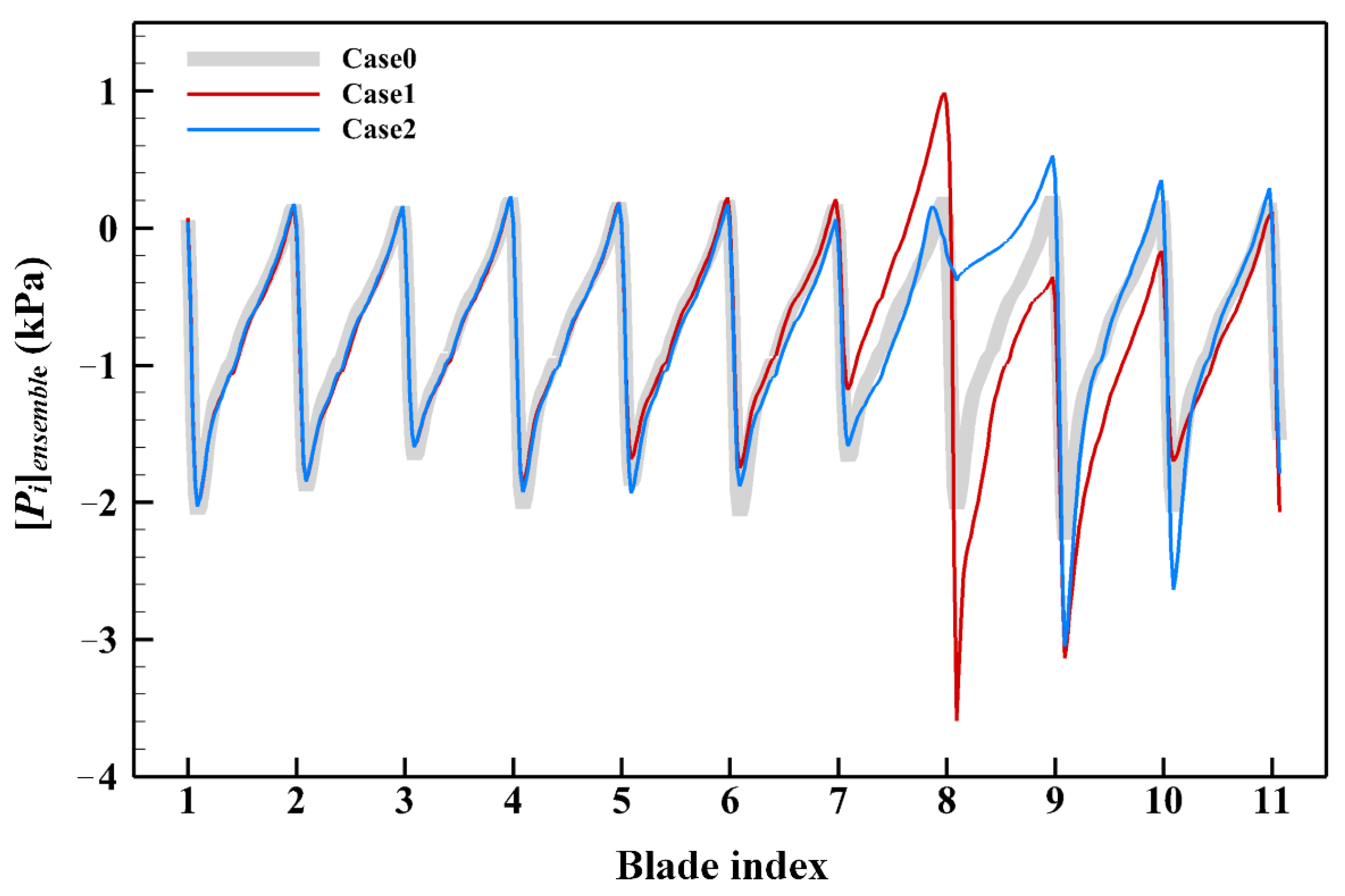
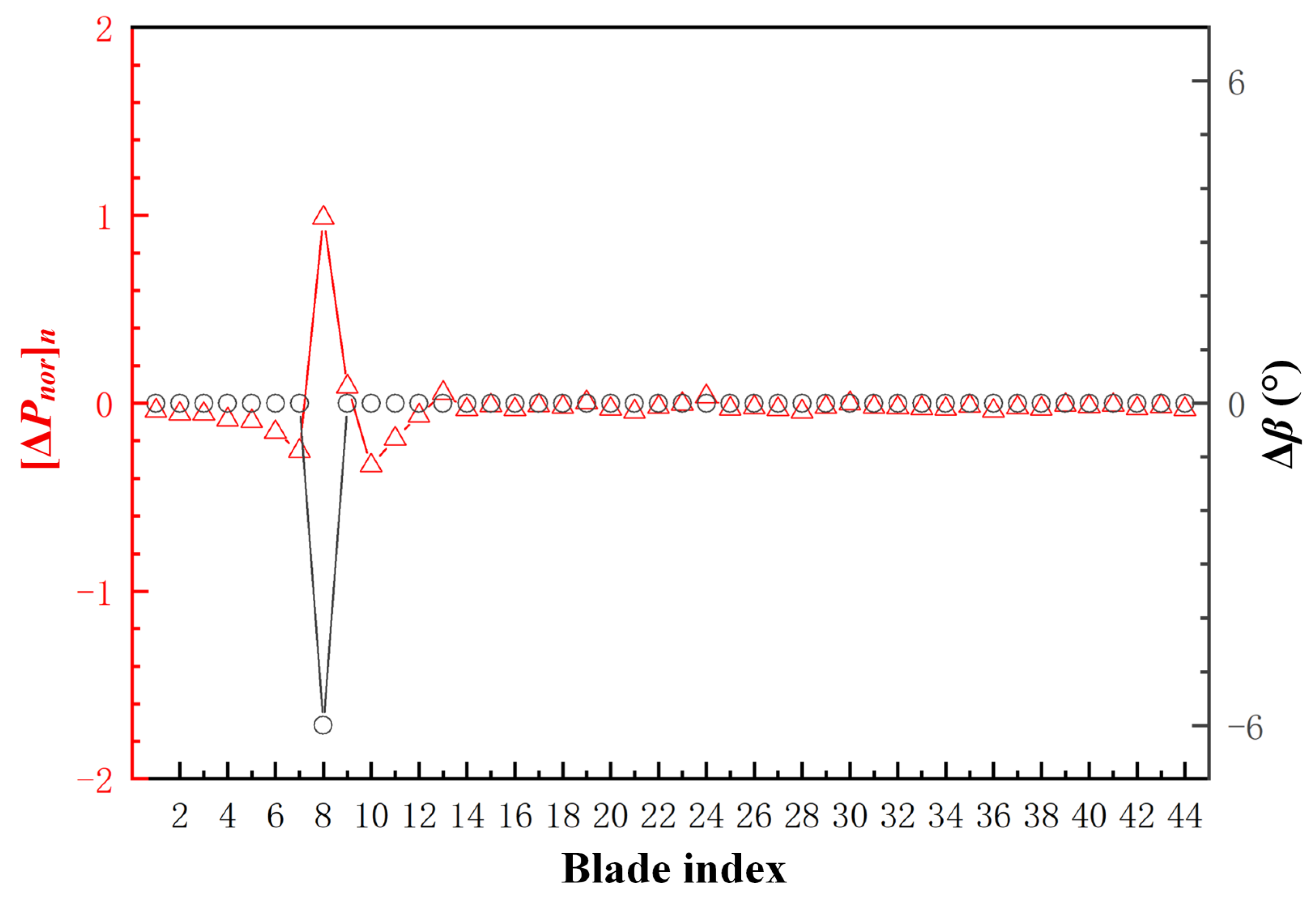
  • The non-uniformity in stagger angle changes the aerodynamic load distribution on the blades, with some blades experiencing an increase in load. In this paper, the blade with the maximum load of the 44 blades is considered the “dangerous blade.” As the compressor throttles to near-stall point, the “dangerous blade” is the first to reach an unstable condition.
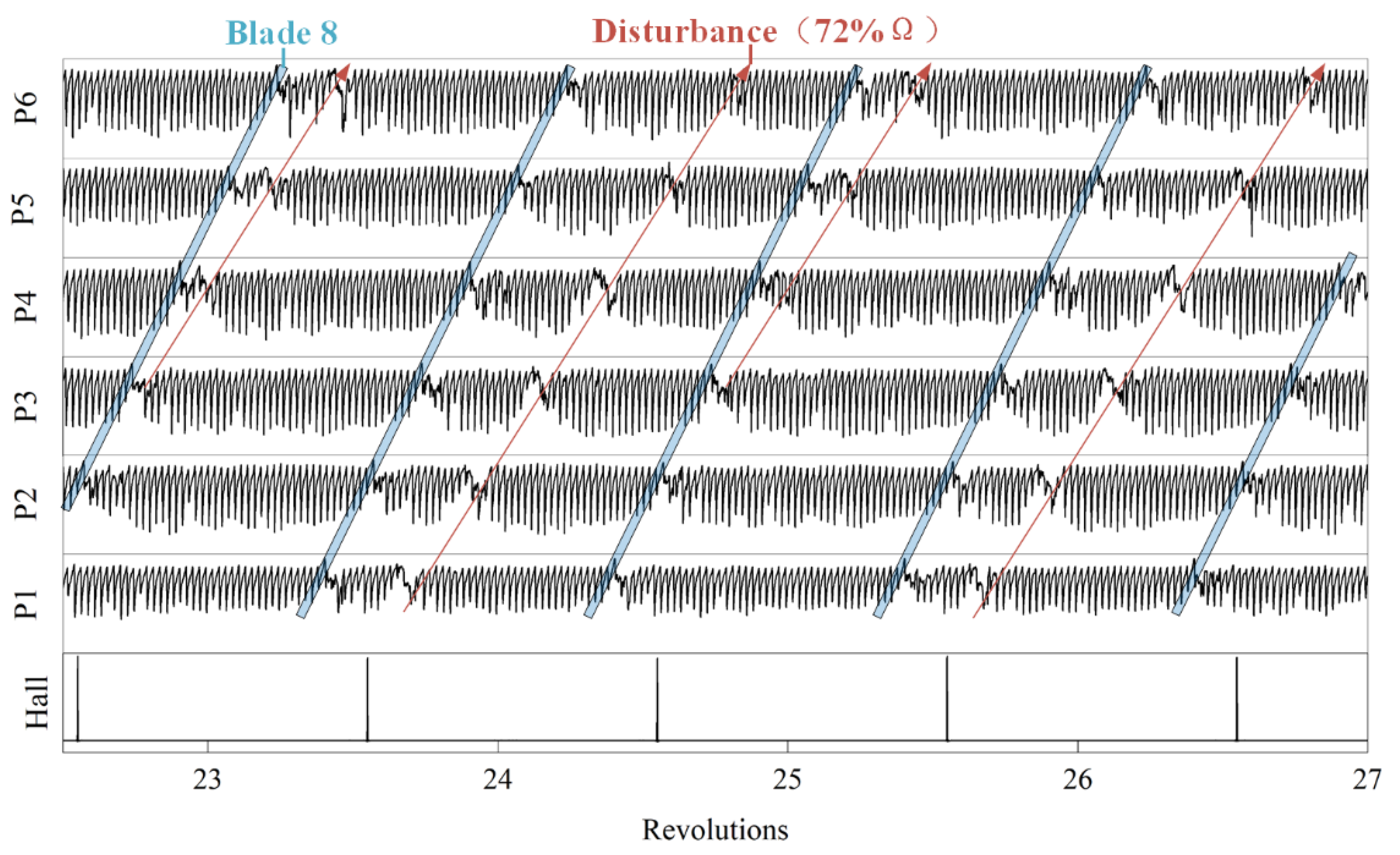
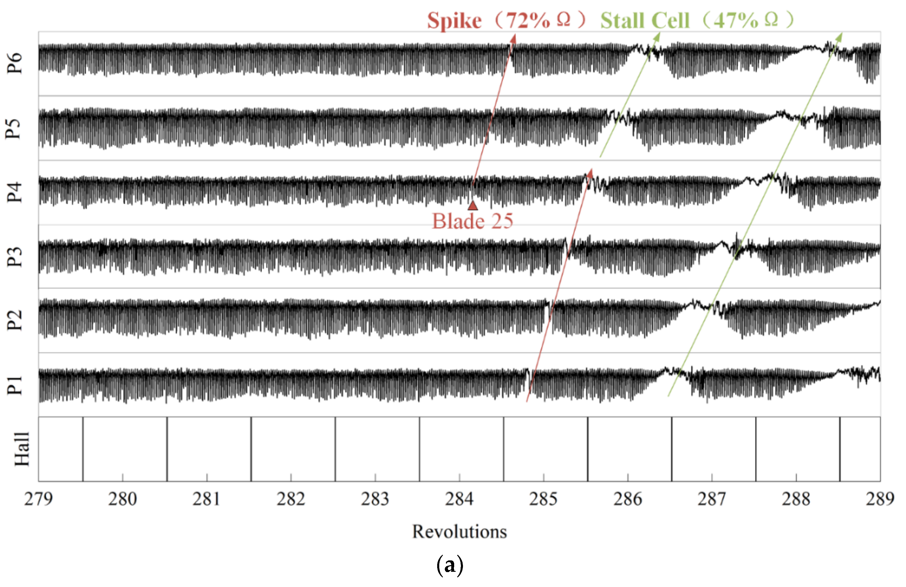
  • Investigation of the stall inception process shows that the unstable disturbance that causes the compressor to come to rotation stall is first generated at the position of the “dangerous blade.” The “dangerous blade,” caused by the non-uniformity in stagger angles, is the direct reason for the advance in the compressor rotating stall.

Author Contributions

S.M. contributed to the methodology, experiment conduction, and original manuscript writing. J.H. contributed to the methodology and review. X.W. contributed to the experiment conduction. J.J. contributed to the review. All authors have read and agreed to the published version of the manuscript.

Funding

The research was funded by the National Science and Technology Major Project of China (grant No. 2017-II-0004-0017).

Acknowledgments

The authors would like to acknowledge the support of the National Science and Technology Major Project.

Conflicts of Interest

The authors declare no potential conflict of interest with respect to the research, authorship, and/or publication of this paper.

References

  1. Schwerdt, L.; Panning-von Scheidt, L.; Wallaschek, J. A Model Reduction Method for Bladed Disks With Large Geometric Mistuning Using a Partially Reduced Intermediate System Model. J. Eng. Gas Turbines Power-Trans. ASME 2021, 143, 071031. [Google Scholar] [CrossRef]
  2. Wilson, M.; Imregun, M.; Sayma, A. The effect of stagger variability in gas turbine fan assemblies. J. Turbomach.-Trans. ASME 2007, 129, 404–411. [Google Scholar] [CrossRef]
  3. Hoyniak, D.; Fleeter, S. Forced Response Analysis of an Aerodynamically Detuned Supersonic Turbomachine Rotor. J. Vib. Acoust. Stress Reliab. Des. 1986, 108, 117–124. [Google Scholar] [CrossRef]
  4. Hawkings, D. Multiple tone generation by transonic compressors. J. Sound Vib. 1971, 17, 241–250. [Google Scholar] [CrossRef]
  5. Stratford, B.; Newby, D. A new look at the generation of buzz-saw noise. In Proceedings of the 4th Aeroacoustics Conference, Atlanta, GA, USA, 3–5 October 1977; American Institute of Aeronautics and Astronautics: Reston, VA, USA, 1977. [Google Scholar]
  6. Han, F.; Sharma, A.; Paliath, U.; Shieh, C. Multiple pure tone noise prediction. J. Sound Vib. 2014, 333, 6942–6959. [Google Scholar] [CrossRef] [Green Version]
  7. Hoyniak, D.; Fleeter, S. The Effect of Circumferential Aerodynamic Detuning on Coupled Bending-Torsion Unstalled Supersonic Flutter. J. Turbomach. 1986, 108, 253–260. [Google Scholar] [CrossRef]
  8. Kaza, K.R.V.; Kielb, R.E. Flutter of turbofan rotors with mistuned blades. AIAA J. 1984, 22, 1618–1625. [Google Scholar] [CrossRef]
  9. Sadeghi, M.; Liu, F. Computation of Mistuning Effects on Cascade Flutter. AIAA J. 2001, 39, 22–28. [Google Scholar] [CrossRef] [Green Version]
  10. Ekici, K.; Kielb, R.E.; Hall, K.C. The effect of aerodynamic asymmetries on turbomachinery flutter. J. Fluids Struct. 2013, 36, 1–17. [Google Scholar] [CrossRef]
  11. Day, I.J. Stall, Surge, and 75 Years of Research. J. Turbomach. 2015, 138, 011001. [Google Scholar] [CrossRef]
  12. Reitz, G.; Schlange, S.; Friedrichs, J. Design of Experiments and Numerical Simulation of Deteriorated High Pressure Compressor Airfoils. In Turbo Expo: Power for Land, Sea, and Air; Volume 2A: Turbomachinery; American Society of Mechanical Engineers: New York, NY, USA, 2016. [Google Scholar]
  13. Pullan, G.; Young, A.M.; Day, I.J.; Greitzer, E.M.; Spakovszky, Z.S. Origins and Structure of Spike-Type Rotating Stall. J. Turbomach. 2015, 137, 051007. [Google Scholar] [CrossRef]
  14. Perovic, D.; Hall, C.A.; Gunn, E.J. Stall Inception in a Boundary Layer Ingesting Fan. J. Turbomach. 2019, 141, 091007. [Google Scholar] [CrossRef]
  15. Suriyanarayanan, V.; Rendu, Q.; Vahdati, M.; Salles, L. Effect of Manufacturing Tolerance in Flow Past a Compressor Blade. J. Turbomach. 2021, 144, 041005. [Google Scholar] [CrossRef]
  16. Zheng, S.; Teng, J.; Wu, Y.; Guo, F.; Lu, S.; Qiang, X. Impact of Nonuniform Stagger Angle Distribution on High-Pressure Compressor Rotor Performance. In Turbo Expo: Power for Land, Sea, and Air; Volume 2A: Turbomachinery; American Society of Mechanical Engineers: New York, NY, USA, 2018. [Google Scholar]
  17. Phan, H.M.; He, L. Efficient Steady and Unsteady Flow Modeling for Arbitrarily Mis-Staggered Bladerow Under Influence of Inlet Distortion. J. Eng. Gas Turbines Power 2021, 143, 071009. [Google Scholar] [CrossRef]
  18. Wang, F.; di Mare, L. Analysis of Transonic Bladerows With Non-Uniform Geometry Using the Spectral Method. J. Turbomach. 2021, 143, 121012. [Google Scholar] [CrossRef]
  19. Nishioka, T.; Kuroda, S.; Kozu, T. Influence of Rotor Stagger Angle on Rotating Stall Inception in an Axial-Flow Fan. In Turbo Expo: Power for Land, Sea, and Air; Turbo Expo 2003, Parts A and B; American Society of Mechanical Engineers: New York, NY, USA, 2003; Volume 6, pp. 901–910. [Google Scholar]
  20. Yoon, Y.S.; Song, S.J.; Shin, H.-W. Influence of Flow Coefficient, Stagger Angle, and Tip Clearance on Tip Vortex in Axial Compressors. J. Fluids Eng. 2006, 128, 1274–1280. [Google Scholar] [CrossRef]
  21. Hoying, D.A.; Tan, C.S.; Vo, H.D.; Greitzer, E.M. Role of Blade Passage Flow Structures in Axial Compressor Rotating Stall Inception. In Turbo Expo: Power for Land, Sea, and Air; Turbomachinery; American Society of Mechanical Engineers: New York, NY, USA, 1998; Volume 1. [Google Scholar]
Figure 1. Sketch of the experimental rig.
Energies 15 02714 g001
Figure 2. Steady and unsteady measurement layout.
Energies 15 02714 g002
Figure 3. Diagram of the definition of the stagger angle.
Energies 15 02714 g003
Figure 4. Schematic diagram of the three stagger angle settings in the experiment: (a) stagger angle setting of Case 0; (b) stagger angle setting of Case 1; (c) stagger angle setting of Case 2.
Energies 15 02714 g004
Figure 5. Installation diagram of the Hall transducer and magnet used in phase-locked technology.
Energies 15 02714 g005
Figure 6. Total-static pressure rise characteristics for three stagger angle settings.
Energies 15 02714 g006
Figure 7. Schematic diagram of the blade passage signal.
Energies 15 02714 g007
Figure 8. Blade passing signal for three stagger angle settings (Φ = 0.580).
Energies 15 02714 g008
Figure 9. Dimensionless load   Δ P n o r n and the change in stagger angle ∆β for Case 1 (Φ = 0.580).
Energies 15 02714 g009
Figure 10. Dimensionless load   Δ P n o r n and the change in stagger angle ∆β for Case 2 (Φ = 0.580).
Energies 15 02714 g010
Figure 11. Blade-to-blade casing static pressure contour variability ( Φ = 0.580 ); (a) for Case 0, (b) for Case 1, and (c) for Case 2.
Energies 15 02714 g011
Figure 12. Blade-to-blade casing static pressure contour variability at near-stall condition (a) for Case 0, (b) for Case 1, and (c) for Case 2.
Energies 15 02714 g012
Figure 13. Casing static pressure trajectory of Case 1 at the near-stall point.
Energies 15 02714 g013
Figure 14. Casing static pressure traces during stall inception (a) for Case 0, (b) for Case 1, and (c) for Case 2.
Energies 15 02714 g014aEnergies 15 02714 g014b
Table 1. Key parameters of the compressor.
ParametersValue
Rotational speed (rpm)1500
Casing diameter (mm)900
Hub-to-tip ratio0.75
Tip clearance (mm)1
Blades number (rotor/stator)44/47
𝑅𝑒𝑐4 × 10⁵
Publisher’s Note: MDPI stays neutral with regard to jurisdictional claims in published maps and institutional affiliations.

