Article

Shielding Sensor Coil to Reduce the Leakage Magnetic Field and Detect the Receiver Position in Wireless Power Transfer System for Electric Vehicle

1
Division of Future Vehicle, Korea Advanced Institute of Science and Technology, Daejeon 34051, Korea
2
The Cho Chun Shik Graduate School of Green Transportation, Korea Advanced Institute of Science and Technology, Daejeon 34051, Korea
*
Author to whom correspondence should be addressed.
Energies 2022, 15(7), 2493; https://doi.org/10.3390/en15072493
Submission received: 18 February 2022 / Revised: 20 March 2022 / Accepted: 24 March 2022 / Published: 28 March 2022
(This article belongs to the Special Issue Next Generation Wireless Charging System for Mobile Devices)

Abstract

:
This paper proposes a shielding sensor (SS) coil to solve the misalignment issue and the leakage magnetic field issue of the wireless power transfer (WPT) system for electric vehicles (EVs). The misalignment issue and leakage magnetic field issue must be solved because they can cause problems with power transfer efficiency reduction and electronic device malfunction. To solve these problems, the proposed SS coils are located over the Tx coil. The newly created mutual inductance between the Tx coil and the SS coil is used to detect the misalignment of the receiver in the Tx coil. In addition, the current phase of the SS coil is adjusted through impedance control of the SS coil to reduce the leakage magnetic field. The proposed SS coils were applied to the standard SAE J2954 model for the wireless charging of an EV. The WPT3/Z2 model of SAE J2954 with output power of 10 kW was simulated to compare the shielding effect according to the power transfer efficiency, and it was confirmed that a shielding effect of 76% was shown under the condition of a 3% reduction in the power transfer efficiency. In addition, the occurrence and direction of the misalignment between the receiver and the Tx coil were confirmed by using the tendency of mutual inductance between each SS coil and the Tx coil. In addition, as in the simulation result, the shielding effect and tendency were confirmed in an experiment conducted with the output power downscaled to 500 W.

1. Introduction

Electric vehicles (EVs), which have emerged to solve various problems, such as environmental pollution caused by the internal combustion engine, provide users and society with many advantages [1]. Therefore, EV sales continue to increase every year, and it is expected that the EV market share will surpass that of internal combustion engine vehicles by 2040. Most of the currently released EVs use the plug-in charging method. The plug-in charging method has a weakness in that it requires a free hand by the driver after parking, as the cable of the charger must be inserted into the charging terminal of the vehicle. Other drawbacks include the uncomfortable contact when handling a much-handled cable, and the fact that large vehicles such as buses require thick and heavy charging cables. In order to address these drawbacks related to plug-in charging, wireless power transfer (WPT) technology is being applied to EV [2,3,4]. Currently, several universities and automakers have released or have plans to release wireless charging EVs, and the standard SAE J2954 for wireless charging EVs has also been published [5]. As an example, the Korea Advanced Institute of Science and Technology (KAIST) has developed a wireless charging electric bus, operating it as a shuttle bus on campus [6].
The inductive power transfer method adopted in the SAE J2954 standard is suitable for application to vehicles due to its high efficiency, stability, and small volume among several WPT methods [7]. As shown in Figure 1, the WPT system, which applies the inductive power transfer method, operates by inducing voltage to the receiving (Rx) coil as a time-varying magnetic field generated from the transmitting (Tx) coil passes through the Rx coil in accordance with Faraday’s law. Compensation circuits are additionally used for high power transfer efficiency, and there are various types of compensation circuits. In the SAE J2954 standard, an LCC–LCC topology with constant current characteristics is used.
Magnetic coupling occurs between the Tx coil and the Rx coil due to a power transfer by using a magnetic field and generally has a low magnetic coupling coefficient k in a WPT system. Therefore, for the WPT3 class of the SAE J2954 standard with a maximum input power of 11.1 kW , a severe leakage magnetic field problem may arise due to a low coupling coefficient. The leakage magnetic field may adversely affect the human body and any medical devices inserted into the human body as well as other electronic equipment in the EV [8]. In addition, there may be a misalignment problem, in which the Tx coil in the charging pad and the Rx coil attached to the vehicle cannot be accurately aligned in the WPT system of the EV. Due to this misalignment, the coupling coefficient decreases, not only reducing the power transfer efficiency but also increasing the leakage magnetic field in a specific direction [9].
Previous studies have proposed various methods by which to solve the leakage magnetic field problem and misalignment problem [10,11,12,13,14,15,16,17,18,19,20]. In the case of a leakage magnetic field problem, a passive shield method using a metal material and a shielding coil method were mainly used. The shielding coil method was divided into an active shield method and a reactive shield method according to the presence or absence of an additional power source of the shielding coil. Paper [10] is a representative paper of the passive shield method using ferrite and aluminum metal to suppress the leakage magnetic field generated in the WPT system. Although the leakage magnetic field is reduced by using metallic materials, the added ferrite and aluminum increase the cost and weight of the WPT system. In paper [11], the active shielding coils with additional inverters were applied to the WPT system to reduce the leakage magnetic field. Although the active shielding method showed the shielding effect, the volume of the system increased due to the arrangement of the shielding coil, and the complexity of the system increased due to the additional inverter control. In paper [12], the concept and design method of a resonant reactive shield were proposed. However, the leakage magnetic field was reduced only in a specific region to which the shielding coils were attached, and the volume of the system increased due to the attachment position. A planar resonant reactive shield was proposed a few years later to complement the limitations of the conventional reactive shield [13]. Because the planar resonant reactive shield was located on the WPT coil, the volume of the system is small and the leakage magnetic field is reduced over a wide area. In addition to these methods, various shielding methods have been proposed, but all papers have proposed a method of using the added coil only for one purposed: shielding. Therefore, additional methods are needed to solve the misalignment problem of the WPT system.
In the case of the misalignment problem of WPT system, a sensor coil method was mainly used. In paper [17], the concept of sensor coil was proposed, and it was applied to a dynamic wireless charging system to detect lateral misalignment. In papers [18,19], the position of the Rx coil as well as lateral misalignment was detected accurately by increasing the number of sensor coils. In addition to these papers, various papers have detected the misalignment by using sensor coils. However, sensor coils were also used for only one purposed: misalignment detection. Therefore, both the shielding coil and the sensor coil are required to solve the two problems (leakage magnetic field, misalignment) of the WPT system. This complicates the operation of the WPT system due to several additional coils present in the system and causes problems of increasing cost and volume.
In this paper, we propose a shielding sensor (SS) coil with two functions: a position-detecting function of a receiver for detecting misalignment and a leakage magnetic field reduction function. Unlike previous studies, one additional coil performs two functions, allowing it to solve both problems arising in an EV wireless charging system. The proposed SS coil is used by dividing the conventional one shielding coil into small pieces. Each coil not only reduces the leakage magnetic field in a reactive method, but also detects the position of the receiver by using the mutual inductance between each SS coil and the Tx coil. That is, the proposed SS coil has advantages such as simplicity and low cost compared to previous papers, in which one coil played only one role, by performing two roles.
The proposed SS coil was applied to standard SAE J2954 models to verify its feasibility. The models were designed by using an ANSYS Maxwell 3D simulation and a PSIM simulation, and the shielding function according to the power transfer efficiency and receiver position detection function were confirmed. In addition, the performance of the SS coil was proved through experiments.
This paper is organized as follows. A circuit analysis and an equation analysis are conducted to explain the principle of the proposed SS coil in Section 2. In Section 3, the proposed SS coil is applied to the EV wireless charging standard SAE J2954 model to perform the leakage magnetic reduction simulation and the receiver position detection simulation. In Section 4, the performances of the proposed SS coil are verified through experiments. Finally, Section 5 provides the conclusion.

2. Proposed Shielding Sensor Coil to Reduce the Leakage Magnetic Field and Detect the Receiver Position in a Wireless Power Transfer System

Figure 2 shows the WPT system with SS coils added to reduce the leakage magnetic field and detect the receiver position. Only SS coils are added to the conventional WPT system, and the added SS coils are located on the Tx coil.
Figure 3 shows the equivalent circuit of the WPT system without the receiver and when charging is not yet underway. At this time, mutual inductance occurs between the Tx coil and each SS coil due to the linkage magnetic flux. The corresponding magnitude is calculated as follows:
M T x S S = k L T x L S S .
As shown in Figure 2, when each SS coil is symmetrically positioned over the Tx coil, the calculation of the mutual inductance between the Tx coil and each SS coil shows identical values,
M T x S S 1 = M T x S S 2 = M T x S S 3 = M T x S S 4 .
Unlike the situation without a receiver, when the receiver is in place for charging, new mutual inductance occurs between the Tx coil and the receiver, and between the SS coil and the receiver. Due to symmetry, Figure 4 shows the equivalent circuit when only one SS coil exists; in order to calculate the mutual inductance difference, Kirchhoff’s voltage law (KVL) is applied to the equivalent circuit as follows:
0 = ( R R e c e i v e r + j ω L R e c e i v e r ) I R e c e i v e r j ω M T x R e c e i v e r I T x + j ω M S S R e c e i v e r I S S
V T x = ( R T x + j ω L T x + 1 j ω C T x ) I T x j ω M T x S S I S S j ω M T x R e c e i v e r I R e c e i v e r
0 = ( R S S + j ω L S S + 1 j ω C S S ) I S S j ω M T x S S I T x + j ω M S S R e c e i v e r I R e c e i v e r .
From Equations (3)–(5), the original mutual inductance between the Tx coil and the SS coil changes, as follows:
M = M T x S S j ω M T x R e c e i v e r M S S R e c e i v e r R R e c e i v e r + j ω L R e c e i v e r .
The mutual inductance between the Tx coil and each SS coil changes depending on the location of the receiver, as expressed in Equation (6), meaning that the mutual inductance difference between the Tx coil and each SS coil is used to detect the receiver. By detecting the position of the receiver, it is possible to detect the direction of the misalignment and the direction to be moved to be aligned.
In addition, as shown in Figure 3, voltage is induced in each SS coil by Faraday’s law, and the induced voltage magnitudes for each SS coil also have identical values due to symmetry.
The magnetic field generated in the WPT system is expressed as follows:
B W P T = μ 0 μ r H W P T .
The induced voltage of the SS coil is expressed as follows:
V i n d u c e d = j ω B W P T e j ω t · S .
And the current of the SS coil in Figure 3 is then calculated as follows:
I S S = V i n d u c e d Z S S = j ω B W P T e j ω t · S ( j ω L S S + 1 j ω C S S ) + R S S
The impedance of the SS coil determines the relationship between the resonance frequency of the SS coil and the operating frequency of the system, as shown in Figure 5.
As shown in Figure 5a, where the impedance of the capacitance of the SS coil ( C S S ) is larger than the impedance of the inductance of the SS coil ( L S S ), the resonance frequency of the SS coil becomes larger than the system operating frequency, and the SS coil operates in the capacitive region. The current of the SS coil operating in the capacitive region is calculated from [12] as follows:
I S S = j ω B W P T e j ω t · S ( j ω L S S + 1 j ω C S S ) + R S S j ω B W P T e j ω t · S 1 j ω C e q + R S S ω 2 B W P T e j ω t · S 1 C e q
where
1 ω C S S ω L S S ,     1 C e q = 1 C S S ω 2 L S S .
The current of the SS coil in the capacitive region is in phase with the magnetic field generated by the WPT system, as expressed by Equation (7). As a result, the leakage magnetic field increases. However, as shown in Figure 5b, where the impedance of the capacitance ( C S S ) of the SS coil is smaller than the impedance of the inductance ( L S S ) of the SS coil, the resonance frequency of the SS coil becomes smaller than the system operating frequency, and the SS coil operates in the inductive region. The current of the SS coil operating in the inductive region is calculated from [12] as follows:
I S S = j ω B W P T e j ω t · S ( j ω L S S + 1 j ω C S S ) + R S S j ω B W P T e j ω t · S j ω L e q + R S S B W P T e j ω t · S L e q
where
1 ω C S S ω L S S ,     L e q = L S S 1 ω 2 C S S .
As a result, as indicated in Equation (11), the shielding coil operating in the inductive region has a phase difference of 180 degrees from the magnetic field generated by the WPT system, thereby reducing the leakage magnetic field.
Figure 6 shows the magnetic field by the WPT system and the current of the SS coil operating in the inductive region. The current phase of the SS coil operating in the inductive region has a phase difference of 180 degrees from the magnetic field generated by the WPT system, resulting in a magnetic field shielding effect.

3. Application and Simulation of the Shielding Sensor Coil

3.1. Application of a Shielding Sensor Coil to the SAE J2954 Standard

Figure 7 shows the SS coil system applied to the WPT3/Z2 model of the standard SAE J2954 for wireless charging of an EV. The WPT3/Z2 model used in the simulation is designed according to the standard, and the structural and electrical parameter values of the model with the SS coils are shown in Table 1 and Table 2.

3.2. Simulation Verification of the Shielding Sensor Coil

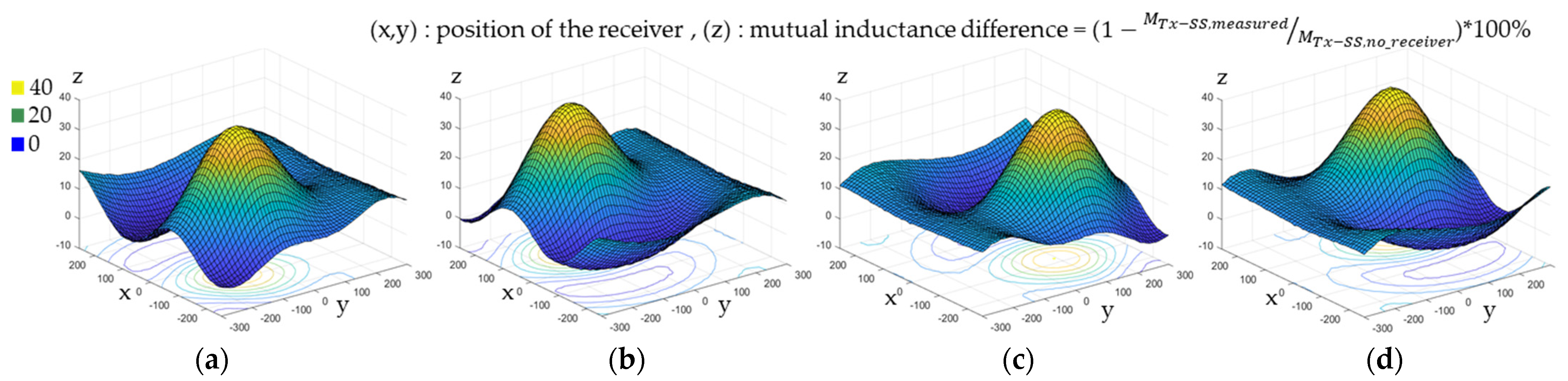
3.2.1. Simulation of the Position-Detection Performance

By detecting the position of the receiver, it is possible to detect whether a misalignment occurs and the direction of the misalignment. Therefore, the simulations were conducted by locating the receiver at 3484 points on the Tx coil to verify the position detection performance as shown in Figure 8. At each point, the tendency of the mutual inductance difference between each SS coil and the Tx coil was confirmed, and through this, it was confirmed that misalignment detection was possible.
Figure 9 shows the mutual inductance difference between each SS coil and the Tx coil according to the x and y positions of the receiver. It can be confirmed that the mutual inductance of each SS coil changes depending on the location of the receiver and that the mutual inductance difference of the SS coil located close to the receiver is significant. In other words, if the mutual inductance of SS coil 1 changes by approximately 40%, as shown in Figure 9a, the receiver is located near SS coil 1.
Figure 10 shows the mutual inductance difference of each SS coil according to the position of the receiver for three cases. Figure 10a shows that the receiver is located at the (−100,50) position, that is, toward the SS coil 2, and the mutual inductance difference of SS coil 2 is largest compared to other SS coils. Figure 10b shows that the mutual inductance difference of all SS coils is identical when the receiver is precisely aligned with the Tx coil. Figure 10c shows that the mutual inductance difference of the SS coil 3 and SS coil 4 is large when the receiver is biased toward SS coil 3 and SS coil 4. That is, Figure 9 and Figure 10 demonstrate that if the mutual inductance difference of a specific SS coil is relatively large, the receiver is located at the corresponding position. In other words, the receiver is aligned with the Tx coil when the mutual inductance difference of all SS coils is equal, and in order to align with the Tx coil, the receiver must move to the SS coil that has a small mutual inductance difference.

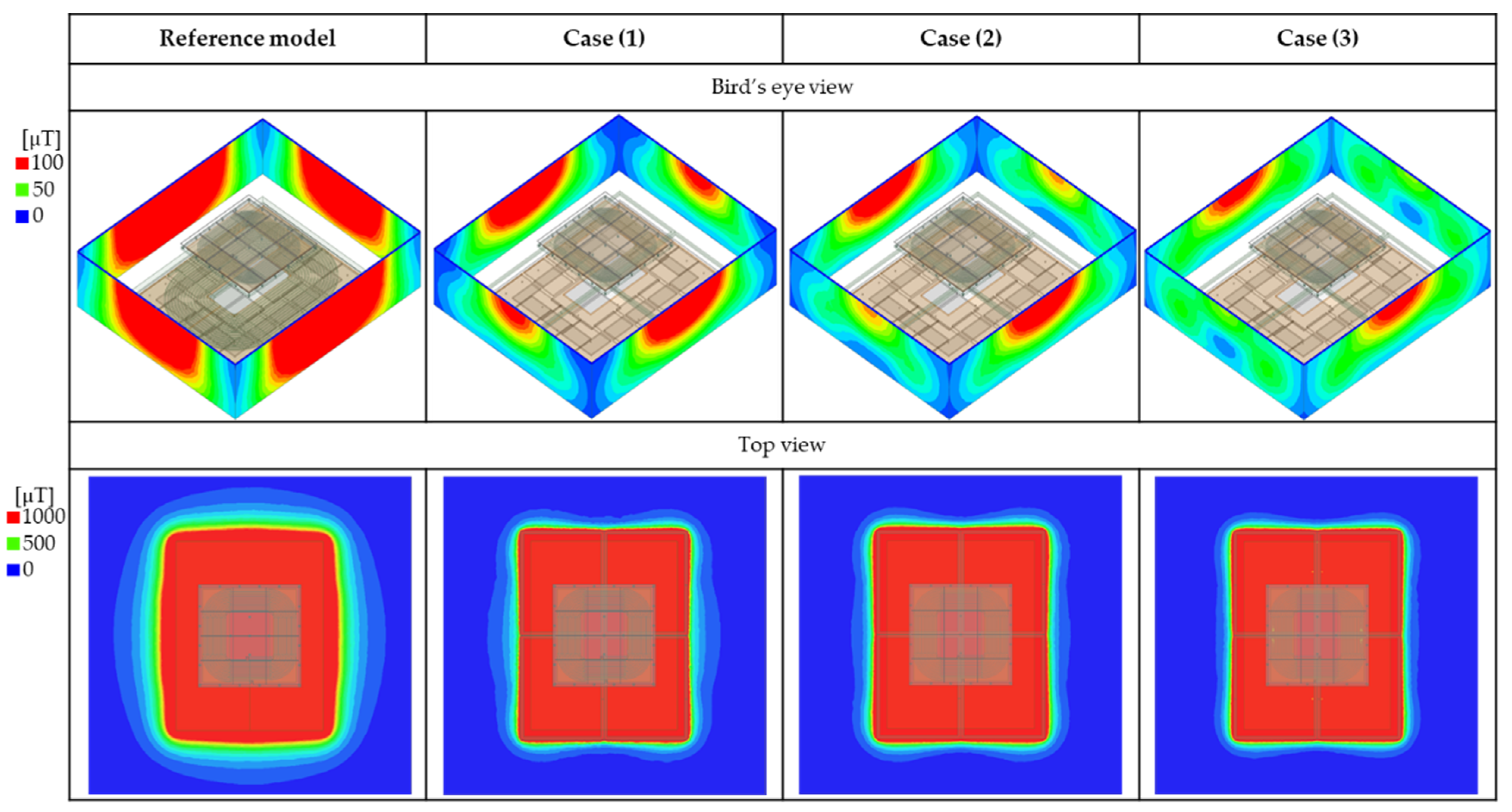
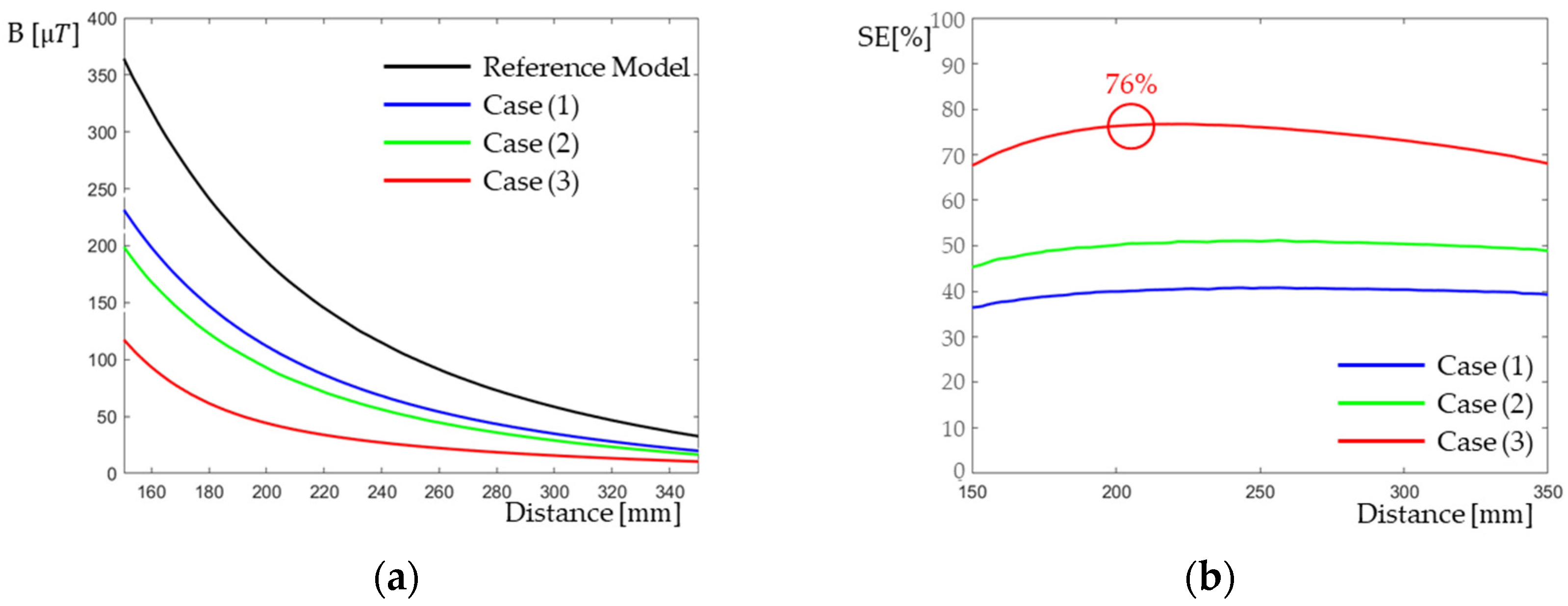
3.2.2. Simulation of the Leakage Magnetic Field Reduction Performance

As shown in Figure 11, in order to verify the leakage magnetic field reduction performance, the simulation was conducted by applying SS coils to the WPT3/Z2 model of the SAE J2954 standard. The electrical parameters of the circuit are designed according to the standard, and their values are shown in Table 3.
A PSIM simulation was used to confirm the current flowing in each coil and the efficiency, and an ANSYS Maxwell 3D simulation was used to confirm the effect of reducing the leakage magnetic field.
Current flowing in the SS coil reduces the power transfer efficiency of the system due to the loss in the SS coil. When the current magnitude of the SS coil is large, the shielding effect increases, but the power transfer efficiency decreases further. As shown in Figure 12, the current magnitude of the SS coil changes according to the resonance frequency of the SS coil. The resonance frequency of the SS coil must be less than the operating frequency of the system in order to operate in the inductive region, as expressed in Equation (6).
When the resonance frequency is low, as in case (1) of Figure 12, the impedance at the operating frequency is large, meaning that the current magnitude of the SS coil is small. Conversely, when the resonance frequency is high, as in case (3) of Figure 12, the impedance at the operating frequency is small, and thus the current magnitude of the SS coil is large. In this paper, three cases that cause a decrease in the power transfer efficiency of 1%, 2%, and 3% were analyzed to confirm the shielding effect. For the reference model to which SS coils are not applied and for the three cases to which the SS coils are applied, the output power, power transfer efficiency, and current magnitude are shown in Table 4.
Figure 13 shows the leakage magnetic field of the reference model and the models to which the SS coils are applied. Compared to the reference model, the leakage magnetic field of the models to which the SS coils are applied was reduced. In addition, a greater shielding effect (SE) appeared due to the increased current from case (1) to case (3),
S h i e l d i n g   e f f e c t   ( S E ) = ( 1 B P r o p o s e d B R e f e r e n c e ) × 100 % .
To compare the magnitude of the leakage magnetic field and numerically confirm the SE, the leakage magnetic field was measured 150 mm away from the end of the Tx ferrite to 350 mm away, as shown in Figure 14.
The magnitude of the leakage magnetic field measured in the reference model and the proposed model are shown in Figure 15a. The models to which the proposed SS coils are applied are confirmed to have a smaller leakage magnetic field than the reference model. In addition, it is confirmed that the magnitude of the leakage magnetic field further decreases from Case (1) to Case (3). In Case (3), which had the smallest leakage magnetic field, SE up to 76% was shown compared to the reference model, as shown in Figure 15b.

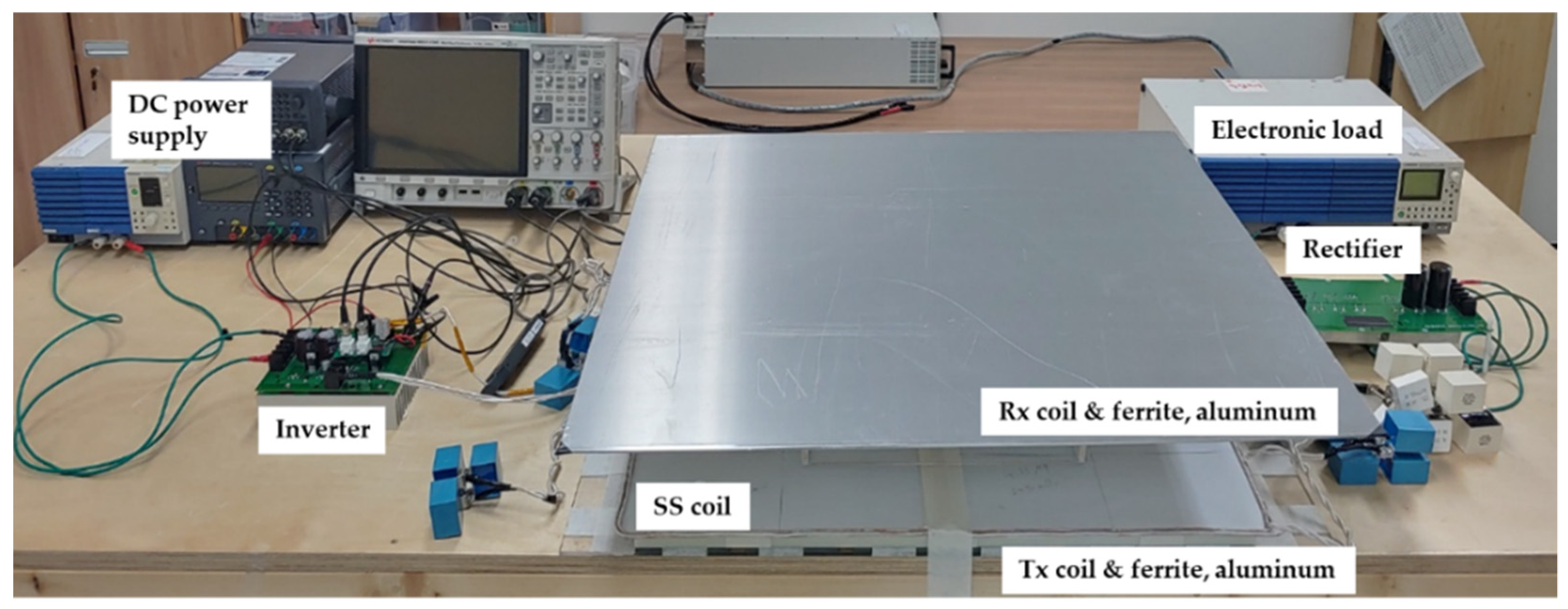
4. Experiment of Shielding Sensor Coil

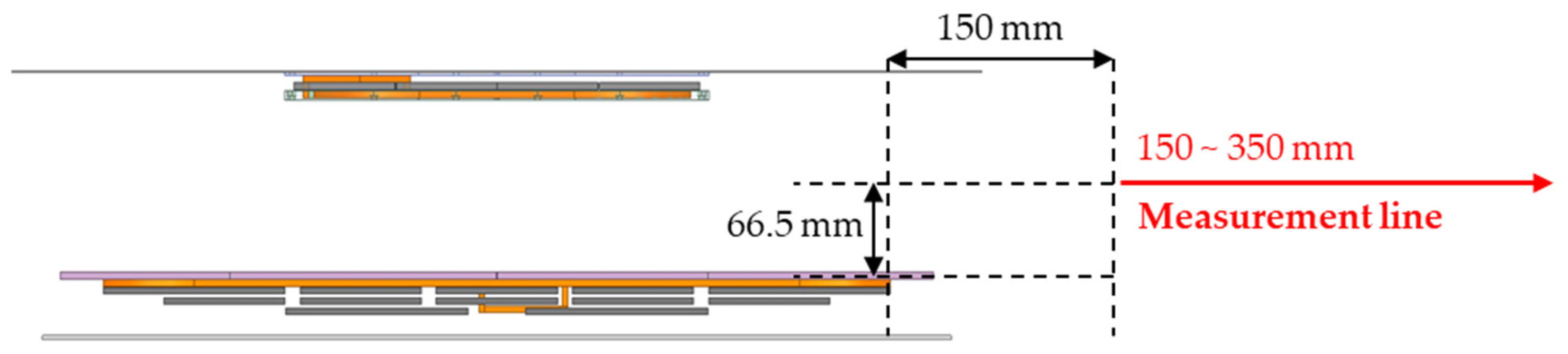
4.1. Experimental Setup

As shown in Figure 16, the experiments were conducted to confirm the position-detection performance and leakage magnetic field reduction performance of the proposed SS coil. The SAE J2954 standard model was used in the experiment, and all structural and electrical parameters were designed to meet the standard.

4.2. Experiment of Position-Detection Performance

As shown in Figure 17, the experiment was conducted on three cases, as in the simulation. As shown in Figure 17a, when the receiver is biased toward the SS coil 2, mutual inductance difference of the SS coil 2 is largest compared to other SS coils. In addition, when the receiver is aligned with the Tx coil as shown in Figure 17b, the mutual inductance differences of all SS coils are identical, and when the receiver is biased toward SS coil 3 and SS coil 4, as shown in Figure 17c, the mutual inductance difference of SS coil 3 and SS coil 4 is large. Through the experiments, it was confirmed that results similar to those of the simulation came out. In other words, the experiments demonstrated, that when the receiver is aligned, the mutual inductance differences of all SS coils are similar, and when biased to a specific location, the mutual inductance differences of SS coils located in a biased location are large.

4.3. Experiment of Leakage Magnetic Field Reduction Performance

The experiment to assess the leakage magnetic field reduction performance focused on a case that caused an efficiency reduction of 3% and output power of 500 W. The input power, output power, and power transfer efficiency according to the presence or absence of SS coils are shown in Table 5.
Figure 18 shows the magnitude of the leakage magnetic field and the shielding effect depending on the presence or absence of SS coils. The leakage magnetic field was measured 15 cm away from the end of the Tx coil ferrite to 55 cm in units of 10 cm. As shown in Figure 18a, due to the application of the SS coil, the magnitude of the leakage magnetic field decreased at all points; moreover, as shown in Figure 18b, the SE was confirmed to be as high as 44.5%. Unlike the simulation, there is a change in the magnitude and SE of the leakage magnetic field because it was downscaled by 1/20 at 500 W. However, the proposed SS coil still shows excellent SE in the 500 W system.

5. Conclusions

In this paper, an SS coil capable of reducing the leakage magnetic field and detecting the position of a receiver has been proposed. The proposed SS coil was applied to an EV WPT system of the type where leakage magnetic field problems and misalignment problems are likely to occur together. For practical use, a simulation and an experiment were conducted on an EV wireless charging standard SAE J2954 model, and the performance capabilities with regard to the two roles of the SS coil were confirmed in the simulation and experiment. The location of the receiver could be confirmed through the mutual inductance difference between the SS coil and the Tx coil, and the tendency of the mutual inductance difference depending on the location of the receiver was confirmed. In addition, the magnitude of the leakage magnetic field and the SE according to the magnitude of the shielding current were confirmed, and the tendency of the SE according to the reduction in power transfer efficiency was confirmed. The proposed SS coil can be applied to various systems with WPT technology, which allows the system to operate more safely and efficiently. Particularly, the added coil has an excellent advantage not only in terms of cost but also in terms of function by solving two major issues occurring in the WPT system.

Author Contributions

Conceptualization, S.S. and S.W.; methodology, S.S., S.W. and H.K.; validation, S.S., S.W., S.L. and J.A.; formal analysis, S.S., S.W. and S.H.; investigation, S.S., S.W., S.H. and S.L.; writing—original draft preparation, S.S.; writing—review and editing, S.S., S.W., H.K., J.A., S.H., S.L. and S.A.; supervision, S.A. All authors have read and agreed to the published version of the manuscript.

Funding

This work was supported by Institute of Information & communications Technology Planning & Evaluation (IITP) grant funded by the Korea government (MSIT) (No. 2020-0-00839, Development of Advanced Power and Signal EMC Technologies for Hyper-connected E-Vehicle).

Data Availability Statement

The data presented in this study are available on request from the corresponding author.

Conflicts of Interest

The authors declare no conflict of interest.

References

  1. Crabtree, G. The coming electric vehicle transformation. Science 2019, 366, 422–424. [Google Scholar] [CrossRef] [PubMed] [Green Version]
  2. Li, S.; Mi, C.C. Wireless power transfer for electric vehicle applications. IEEE J. Emerg. Sel. Top. Power Electron. 2014, 3, 4–17. [Google Scholar]
  3. Campi, T.; Cruciani, S.; Maradei, F.; Feliziani, M. Magnetic field during wireless charging in an electric vehicle according to standard SAE J2954. Energies 2019, 12, 1795. [Google Scholar] [CrossRef] [Green Version]
  4. Miller, J.M.; Onar, O.C.; Chinthavali, M. Primary-side power flow control of wireless power transfer for electric vehicle charging. IEEE J. Emerg. Sel. Top. Power Electron. 2014, 3, 147–162. [Google Scholar] [CrossRef]
  5. Jiang, L.; Liu, H.; Wang, C. Summary of EMC Test Standards for Wireless Power Transfer Systems of Electric Vehicles. In Proceedings of the 2021 Asia-Pacific International Symposium on Electromagnetic Compatibility (APEMC), Nusa Dua, Bali, Indonesia, 27–30 September 2021; pp. 1–4. [Google Scholar]
  6. Song, B.; Shin, J.; Lee, S.; Shin, S.; Jeon, S.; Jung, G. Design of a High-Power Transfer Pickup for On-Line Electric Vehicle (OLEV). In Proceedings of the IEEE International Electric Vehicle Conference, Greenville, SC, USA, 4–8 March 2012; pp. 1–4. [Google Scholar]
  7. Covic, G.A.; Boys, J.T. Inductive power transfer. Proc. IEEE 2013, 101, 1276–1289. [Google Scholar] [CrossRef]
  8. Campi, T.; Cruciani, S.; de Santis, V.; Maradei, F.; Feliziani, M. EMC and EMF Safety Issues in Wireless Charging System for an Electric Vehicle (EV). In Proceedings of the International Conference of Electrical and Electronic Technologies for Automotive, Turin, Italy, 15–16 June 2017; pp. 1–4. [Google Scholar]
  9. Abou Houran, M.; Yang, X.; Chen, W. Magnetically coupled resonance WPT: Review of compensation topologies, resonator structures with misalignment, and EMI diagnostics. Electronics 2018, 7, 296. [Google Scholar] [CrossRef] [Green Version]
  10. Kim, H.; Song, C.; Kim, J.; Kim, J.; Kim, J. Shielded Coil Structure Suppressing Leakage Magnetic Field from 100W-Class Wireless Power Transfer System with Higher Efficiency. In Proceedings of the IEEE MTT-S International Microwave Workshop Series on Innovative Wireless Power Transmission: Technologies, Systems, and Applications, Kyoto, Japan, 10–11 May 2012; pp. 83–86. [Google Scholar]
  11. Campi, T.; Cruciani, S.; Maradei, F.; Feliziani, M. Magnetic field mitigation by multicoil active shielding in electric vehicles equipped with wireless power charging system. IEEE Trans. Electromagn. Compat. 2020, 62, 1398–1405. [Google Scholar] [CrossRef]
  12. Kim, S.; Park, H.H.; Kim, J.; Kim, J.; Ahn, S. Design and analysis of a resonant reactive shield for a wireless power electric vehicle. IEEE Trans. Microw. Theory Tech. 2014, 62, 1057–1066. [Google Scholar] [CrossRef]
  13. Park, J.; Kim, D.; Hwang, K.; Park, H.H.; Kwak, S.I.; Kwon, J.H.; Ahn, S. A resonant reactive shielding for planar wireless power transfer system in smartphone application. IEEE Trans. Electromagn. Compat. 2017, 59, 695–703. [Google Scholar] [CrossRef]
  14. Campi, T.; Cruciani, S.; Feliziani, M. Magnetic Shielding of Wireless Power Transfer Systems. In Proceedings of the International Symposium on Electromagnetic Compatibility, Tokyo, Japan, 12–16 May 2014; pp. 422–425. [Google Scholar]
  15. Woo, S.; Shin, Y.; Lee, C.; Huh, S.; Rhee, J.; Park, B.; Son, S.; Ahn, S. EMI Reduction Method for Over-Coupled WPT System Using Series-None Topology. In Proceedings of the IEEE Wireless Power Transfer Conference (WPTC), San Diego, CA, USA, 1–4 May 2021; pp. 1–4. [Google Scholar]
  16. Furukawa, K.; Kusaka, K.; Itoh, J.I. Low-EMF Wireless Power Transfer Systems of Four-Winding Coils with Injected Reactance-Compensation Current as Active Shielding. In Proceedings of the IEEE Applied Power Electronics Conference and Exposition (APEC), Phoenix, AZ, USA, 14–17 June 2021; pp. 1618–1625. [Google Scholar]
  17. Hwang, K.; Park, J.; Kim, D.; Park, H.H.; Kwon, J.H.; Kwak, S.I.; Ahn, S. Autonomous coil alignment system using fuzzy steering control for electric vehicles with dynamic wireless charging. Math. Probl. Eng. 2015, 2015, 205285. [Google Scholar] [CrossRef] [Green Version]
  18. Jung, K.; Park, J.; Son, S.; Ahn, S. Position Prediction of Wireless Charging Electric Vehicle for Auto Parking Using Extreme Gradient Boost Algorithm. In Proceedings of the IEEE Wireless Power Transfer Conference (WPTC), Seoul, Korea, 15–19 November 2020; pp. 439–442. [Google Scholar]
  19. Gao, Y.; Duan, C.; Oliveira, A.A.; Ginart, A.; Farley, K.B.; Tes, Z.T.H. 3-D coil positioning based on magnetic sensing for wireless EV charging. Energies IEEE Trans. Transp. Electrif. 2017, 3, 578–588. [Google Scholar] [CrossRef]
  20. Cortes, I.; Kim, W.J. Lateral position error reduction using misalignment-sensing coils in inductive power transfer systems. IEEE/ASME Trans. Mechatron. 2018, 23, 875–882. [Google Scholar] [CrossRef]
Figure 1. Principle of the inductive power transfer method.
Energies 15 02493 g001
Figure 2. WPT system to which SS coils for reducing a leakage magnetic field and detecting a receiver position is applied.
Energies 15 02493 g002
Figure 3. Equivalent circuit of the proposed WPT system before the receiver enters.
Energies 15 02493 g003
Figure 4. Equivalent circuit of the proposed WPT system with the receiver.
Energies 15 02493 g004
Figure 5. Current phase of the SS coil according to the relationship between the resonant frequency of the SS coil and the operating frequency of the system. (a) Capacitive region (operating frequency < resonance frequency of the SS coil). (b) Inductive region (operating frequency > resonance frequency of the SS coil).
Energies 15 02493 g005
Figure 6. Induced voltage and current phases of the SS coil whose impedance has been adjusted to operate in an inductive region for leakage magnetic field shielding.
Energies 15 02493 g006
Figure 7. SAE J2954 WPT3/Z2 model with the SS coils.
Energies 15 02493 g007
Figure 8. Simulation method of the position-detection performance.
Energies 15 02493 g008
Figure 9. Tendency of the mutual inductance difference of each SS coil according to the position of the receiver. (a) SS coil 1. (b) SS coil 2. (c) SS coil 3. (d) SS coil 4.
Energies 15 02493 g009
Figure 10. Mutual inductance difference of each SS coil according to the position of the receiver. (a) Receiver position: (−100,50). (b) Receiver position: (0,0). (c) Receiver position: (150,0).
Energies 15 02493 g010
Figure 11. SAE J2954 WPT3/Z2 simulation circuit to which SS coils are applied.
Energies 15 02493 g011
Figure 12. Impedance magnitude at the operating frequency according to the resonance frequency of the SS coil.
Energies 15 02493 g012
Figure 13. Comparison of the leakage magnetic field.
Energies 15 02493 g013
Figure 14. Leakage magnetic field measurement line for numerical comparison.
Energies 15 02493 g014
Figure 15. Comparison according to the model. (a) Comparison of the leakage magnetic field. (b) Comparison of the shielding effect.
Energies 15 02493 g015
Figure 16. Experimental setup for the measurement using the SAE J2954 model.
Energies 15 02493 g016
Figure 17. Experimental results of the position-detection performance: (a) Receiver position: (−100,50); (b) Receiver position: (0,0); (c) Receiver position: (150,0).
Energies 15 02493 g017
Figure 18. Experimental results of the leakage magnetic field reduction performance: (a) Comparison of the leakage magnetic field. (b) Comparison of the shielding effect.
Energies 15 02493 g018
Table 1. Structural parameters.
ParameterValue
Tx Turns8 [turns]
Rx Turns9 [turns]
SS Turns2 [turns]
Air Gap132 [mm]
Table 2. Electrical parameters (Inductance).
TxRxSS 1SS 2SS 3SS 4
Tx 37.68   [ μ H ] 6.86   [ μ H ] 0.65   [ μ H ] 0.65   [ μ H ] 0.65   [ μ H ] 0.65   [ μ H ]
Rx 43.81   [ μ H ] 0.69   [ μ H ] 0.69   [ μ H ] 0.69   [ μ H ] 0.69   [ μ H ]
SS 1 4.10   [ μ H ] 1.08   [ μ H ] 0.73   [ μ H ] 0.15   [ μ H ]
SS 2 4.10   [ μ H ] 0.15   [ μ H ] 0.73   [ μ H ]
SS 3 4.10   [ μ H ] 1.08   [ μ H ]
SS 4 4.10   [ μ H ]
Table 3. Electrical parameters of the circuit.
ParameterValue
L T x 37.68   [ μ H ]
L R x 43.81   [ μ H ]
L S S 4.1   [ μ H ]
j X T x 5.3 [Ω]
j X R x −1.4 [Ω]
Operating Frequency85 [kHz]
Table 4. Output power, power transfer efficiency, and current of the comparison models.
Reference ModelProposed Model
Case (1)Case (2)Case (3)
P o u t 10 [kW]
η s y s t e m 93.24 [%]92.12 [%]91.31 [%]89.96 [%]
I T x , p e a k 81.88 0 ° 82.95 0 ° 82.99 0 ° 87.00 0 °
I R x , p e a k 72.74 90 ° 71.95 90 ° 71.57 90 ° 72.82 90 °
I S S , p e a k - 56.44 180 ° 70.90 180 ° 124.77 180 °
Table 5. Power transfer efficiency without and with SS coils.
P i n P o u t η s y s t e m
w/o SS coil 582.85   [ W ] 500   [ W ] 85.79 [%]
w/ SS coil 605.16   [ W ] 500   [ W ] 82.62 [%]
Publisher’s Note: MDPI stays neutral with regard to jurisdictional claims in published maps and institutional affiliations.

