Article

Power Flow Optimization and Economic Analysis Based on High Voltage Phase Shifting Transformer

1
Grid Planning & Research Center, Guangdong Power Grid Corporation, CSG, Shuijungang No. 8, Dongfeng East Road, Guangzhou 510080, China
2
School of Electrical and Automation, Wuhan University, No. 299, Bayi Street, Wuchang District, Wuhan 430072, China
*
Author to whom correspondence should be addressed.
Energies 2022, 15(7), 2363; https://doi.org/10.3390/en15072363
Submission received: 23 February 2022 / Revised: 13 March 2022 / Accepted: 21 March 2022 / Published: 24 March 2022
(This article belongs to the Special Issue Energy, Electrical and Power Engineering 2021-2022)

Abstract

:
With the development of power systems, the power flow problem of transmission line is becoming more and more prominent. This paper presents a power flow regulation method based on phase shifting transformer (PST). Firstly, the working principle and performance of PST are analyzed. Then, the simulation model of BPA multi node system is established. PST access reduces the line imbalance to less than 8%. On this basis, considering the influence of saturation effect and leakage reactance, a PST suitable for 220 kV power grid is designed. Three different working conditions are simulated by PSCAD software. Under normal working conditions and N-1 conditions, PST can increase the transmission limit of the ring network section by more than 20%. When a short-circuit fault occurs, PST can also suppress the fault current. For 220 kV practical projects, unified power flow controller (UPFC) has faster response speed and stronger performance, but PST is more economical and reliable, and the equipment cost is 49.86% lower than that of UPFC. The power flow regulation method based on PST has good steady-state effect. It can improve the utilization efficiency of power grid assets and optimize the power flow distribution in a short time and at low cost.

1. Background

With the development and wide application of new energy, power systems are becoming more and more complex. Transmission lines are characterized by long distance, high voltage, and large capacity [1,2]. The grid connection of new energy leads to the decline of power system reliability, and transmission lines may have overload, circulation, and other problems. How to regulate and optimize the power flow distribution and enhance the reliability of power system has become a hot issue. In the past, the above problems were solved by controlling the operation mode of power system, such as adjusting transformer tap, changing the operation mode of generator set, and switching compensation device [3]. These methods have some limitations and cannot flexibly regulate the power flow.
The flexible AC Transmission Technology (FACTS) provides a method for flexible regulation of power flow. FACTS power flow controllers are mainly divided into two types: power electronic type and electromagnetic type [4]. The power electronic flow controller is based on power electronic equipment, and its typical representative is the unified power flow controller (UPFC). The UPFC can independently regulate the active and reactive power and provide voltage support for the system. In addition, with rapid developments of new energy, the demands for energy storage have been intensively increased [5,6], the DC part of UPFC can install energy storage devices to provide active power support [7], which is more suitable for a new energy power system. The regulating speed of UPFC is very fast, which can quickly respond to the voltage drop on the grid side to improve the low voltage ride through (LVRT) ability [8]. The UPFC has many advantages, but the cost is too high to be applied [9]. The phase shifting transformer (PST) is a power flow controller based on a transformer, which has a simple structure, low cost, and high reliability. The application of some new materials and technologies has effectively improved the reliability of transformers [10,11].
References [12,13,14,15] summarize the engineering application of PST, and PST on-load voltage regulating switches can be divided into mechanical type and thyristor type. In current engineering applications, the mechanical on-load voltage regulating switch is more widely used, and studies on the thyristor PST are mostly on theory and simulation. References [16,17,18] describes the research status of PST and analyzes the advantages and disadvantages of different types of PST and their application scenarios: The thyristor PST has a faster response speed and is suitable for situations requiring a fast dynamic response and a small capacity, but its cost is much higher than that of a mechanical PST. The mechanical switch is suitable for the occasions where the response speed is not high, and the capacity is large. Reference [19] improved the structure of the traditional mechanical PST and proposed a new electromagnetic unified power flow controller (EUPFC), which has a larger adjustment range and a faster response speed than the traditional PST. However, this structure is mostly used for power grids below 110 kV, and its insulation cost will increase significantly when it is applied to high-voltage power grids above 220 kV. Reference [20] analyzed the feasibility of double core symmetric PST to improve steady-state power flow in actual power grid and conducted a simulation study on the control characteristics of PST during switching operation.
PST regulates the line power flow by injecting a compensating voltage. When its voltage regulating switch works at different gears, the equivalent impedance value will also change, affecting the size of the phase shift angle. Therefore, this paper firstly analyzes the influence of PST internal impedance on the phase shift angle regarding the principle aspect. Then, based on BPA and PSCAD software, the simulation study of PST power flow regulation on the multi-node system and actual 220 kV ring network is carried out, and the PST power flow regulation effect under different working conditions is analyzed. Then, combined with the practical engineering application, the economic analysis of PST and UPFC is carried out. Finally, the validity of the theory and simulation is verified by prototype experiment, which provides reference for the implementation of PST engineering in a high voltage power grid.

2. Theoretical Research and Selection of PST

2.1. Working Principle of PST

In transmission line, there is voltage drop and phase angle difference at the beginning and end of the line. When there is no control or regulation device, the power flow of parallel transmission line and ring network is distributed according to impedance. As shown in Figure 1, when the PST is installed in the high-voltage transmission line, it can be equivalent to the ideal transformer and impedance in series.
In Figure 1, US and UL are the voltage amplitude at the head and end of the line. XL and XPST are the equivalent impedance of line and PST, respectively. δS and δL are defined as phase angle at the beginning and end of the line, respectively.
Since the equivalent reactance of the transmission line is much greater than its equivalent resistance, its loss can be ignored. After PST is connected, the active power flow of the line is [21,22]:
P = U S U L X L + X PST sin ( δ S δ L ± θ )
It can be concluded from Equation (1) that PST will add a phase angle of ±θ to the active power transmitted by the line. When the phase shift angle of PST output is positive, the phase difference between the head and end of the line is reduced, so as to reduce the line active power flow. On the contrary, if the PST output phase shift angle is negative, the line transmission power can be increased.
In this paper, PST is proposed to solve the power flow problem of high-voltage power grid. The steps and work of this method are shown in Figure 2. It is generally divided into the research process of theoretical analysis, simulation calculation, and experimental verification. In topology selection and parameter calculation, the actual power grid demand should be combined, and the influence of leakage reactance and saturation effect should be considered.

2.2. Topology Selection of PST

The uneven distribution of 220 kV transmission lines in Guangdong has led to a serious reduction in the utilization rate of 220 kV transmission lines. The power flow regulation technology based on high voltage PST can transfer the overload line power flow to the light load line and increase the power transmission margin of Huizhou station.
PST can be classified from different angles. According to the output compensation voltage regulation characteristics, it can be sorted into longitudinal regulation, transverse regulation, and oblique regulation [23]. According to the output voltage characteristics of the transformer, it can be sorted into symmetrical type and asymmetric type. According to the structure of transformer body, it can be sorted into single core type and double core type [24]. The topologies of various types of PST are shown in Figure 3.

2.2.1. Selection of Transformer Structure

The single-core PST is realized by wiring the windings of a transformer. The double core PST is realized by connecting a series transformer and a parallel transformer (excitation transformer) to the system. The performance pairs of single-core and double core PST are shown in Table 1. Single-core PST has a simple structure, and its on-load tap switch is directly connected to the line, so it has high insulation requirements and is mainly applied to 110 kV and below power systems [25]. The double core PST is suitable for high voltage levels. The voltage level of a ring network system in Guangdong is 220 kV, so it is recommended to choose the double core PST.

2.2.2. Electrical Characteristic Selection

The asymmetric PST changes the voltage amplitude and phase angle simultaneously. Symmetric PST ensures that the voltage amplitude is unchanged before and after compensation and only changes its phase angle [26,27]. The asymmetric and symmetric PST voltage phasor is shown in Figure 4.
In Figure 4, USA, USB, and USC are the three-phase voltages at the first end of the transmission line, respectively. ∆UA, ∆UB, and ∆UC are the series compensation voltage injected into the line by PST; ULA, ULB, and ULC are the compensated three-phase voltage of the line, respectively.
As can be seen from Figure 3, when the voltages are the same, the output phase shift angle of symmetrical PST is larger. Considering the power flow regulation requirements of the new power system, the phase shift angle required by the 220 kV high-voltage ring network system shall be greater than 20°, and the line voltage amplitude shall be kept within the specified range. Generally, a symmetrical PST is selected. Based on the above analysis, it is recommended that 220 kV ring network PST adopt a dual core symmetrical structure.

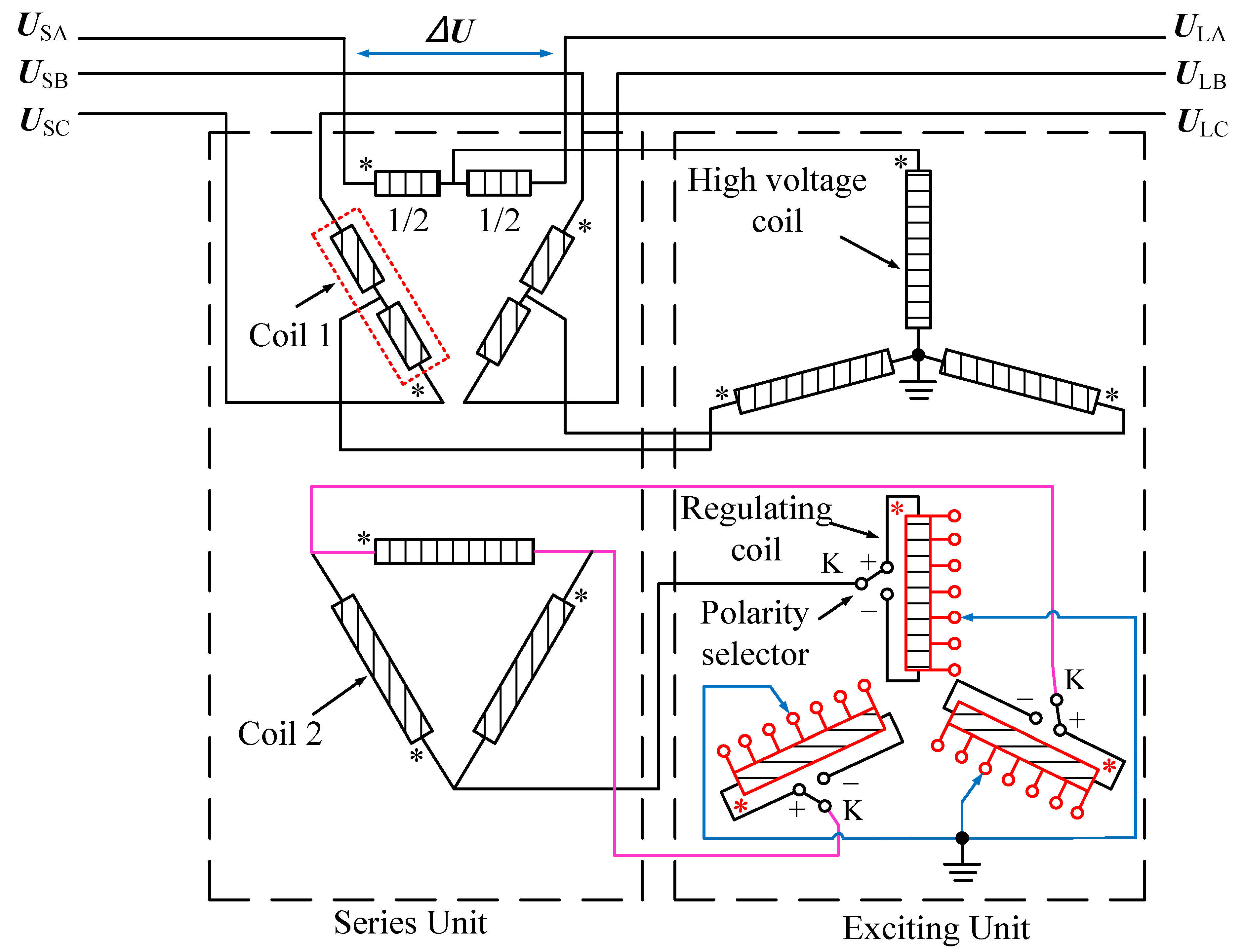
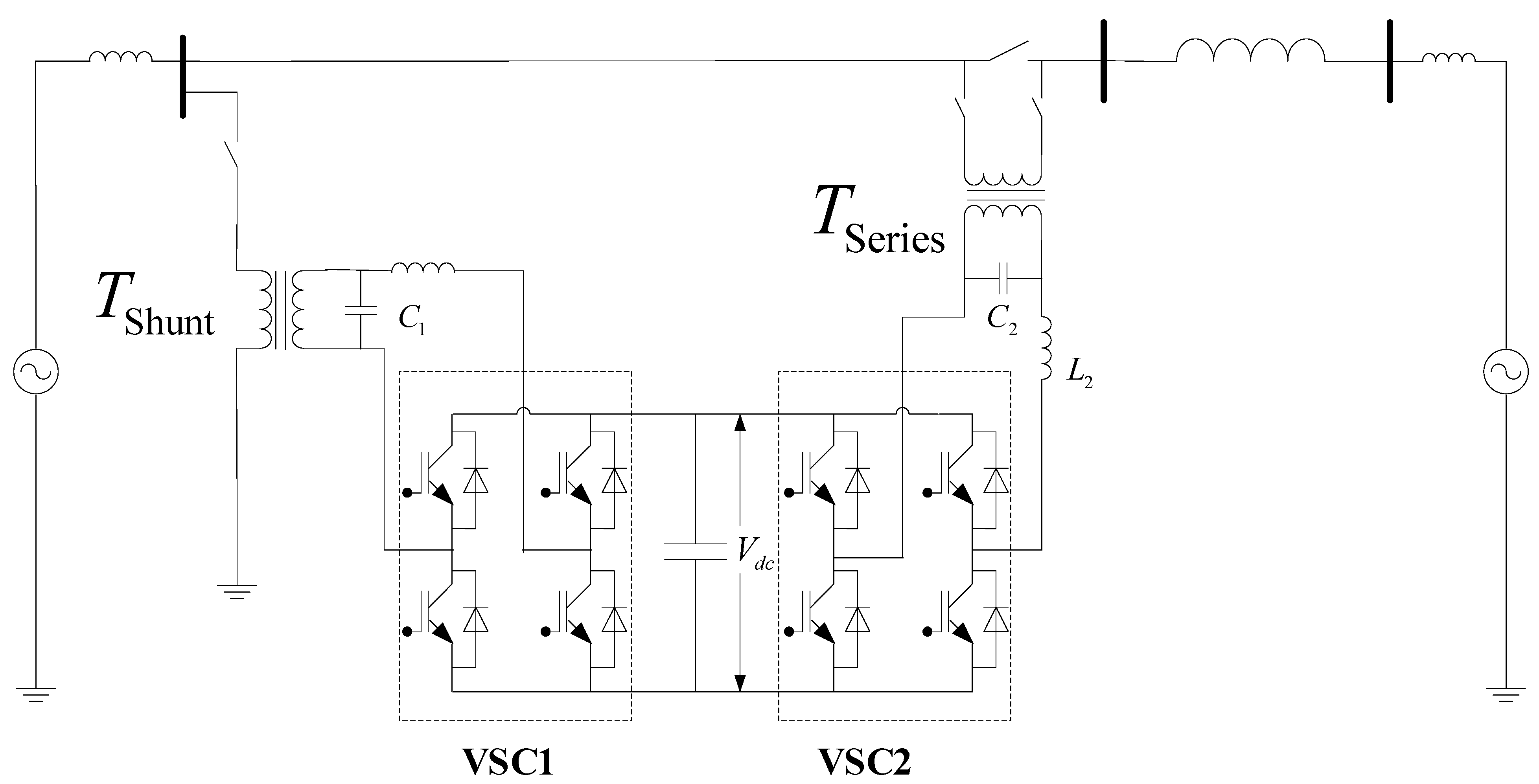
2.3. Equivalent Model of Double Core Symmetric PST

2.3.1. Double Core Symmetric PST Topology

The double core symmetrical PST includes two independent transformers on the magnetic circuit structure, namely, series transformer BT and excitation transformer ET. The connection mode is shown in Figure 5.
The series transformer includes coil 1 and coil 2. The excitation transformer includes two parts: high voltage coil and voltage regulating coil. The high voltage coil connected in “Y” mode in the excitation transformer provides excitation for the voltage regulating coil. The voltage in the voltage regulating coil can be changed by adjusting the switch gear of the voltage regulating coil (a polarity selector is installed to realize the leading/lagging phase adjustment of the PST after switching the positive and negative poles). Voltage regulating coil and series transformer coil 2 are connected by electrical connection to change the voltage of series transformer coil 2, thus generating phase angle adjustment voltage ∆U in coil 1 to achieve voltage phase angle change between the power supply side and the load side. When rated capacity and voltage grade are low, two transformer bodies can be placed in the same box.

2.3.2. Load Equivalent Model

Under load conditions, the output phase shift angle θ of PST is determined jointly by its no-load phase shift angle α and internal phase shift angle β, which affects not only the structure and winding size of transformer but also the selection of tap switch. The primary and secondary sides of ET are star-shaped wiring, and the midpoint of BT primary side winding leads to the primary side of ET, so the first and secondary sides are divided into two parts with equal equivalent impedance [28]. The voltage in the voltage regulating coil can be changed by adjusting the tap position of the on-load voltage regulating coil on the secondary side of ET so as to generate compensation voltage on the primary side of BT and realize the voltage phase shift between the power side and the load side of the line. Double core symmetrical PST three phase equilibrium establishes its A-phase equivalent circuit, as shown in Figure 6.
In Figure 6, the “T” shaped equivalent circuit of the transformer is used for analysis. ZB1 and ZB2 are equivalent leakage impedances of the primary side and secondary side of the series transformer; ZE1 and ZE2 are equivalent leakage impedances of primary side and secondary side of the series transformer. UB2A is the a-phase voltage of the secondary side of the series transformer.
The equivalent impedance of the voltage regulating winding (secondary side) of ET will also change when the adjustable tap position is different. When the maximum adjustable tap position is nmax and the selected tap position is n, the impedance of the secondary side is
Z E 2 n = D Z E 2 D = n n max }
At this point, the overall equivalent impedance of the double core symmetric PST can be expressed as [29]:
Z eq = Z B 1 + 1 3 N B 2 + 4 ( N E / D ) 2 [ 4 ( N E / D ) 2 N B 2 Z B 2 + 12 N B 2 Z E 1 + 12 ( N E / D ) 2 N B 2 Z E 2 D ]
In (3), Zeq is the global equivalent impedance of PST; NB = UB1A/UB2A is the change transformation ratio of series transformer BT; NE = UE1A/UE2A is the transformation ratio of the excitation transformer ET.
When the secondary side switching tap of the excitation transformer is n, the output voltage phasor of PST is shown in Figure 7.
In Figure 7, α is the phase shift angle of PST under no-load condition, and β is the inward phase shift angle. US and IS are the voltage and current on the power supply side of the line. UL0 is the load side voltage under no-load condition. US(L) and US(a) represent the line power supply side voltage under lagging and advancing conditions, respectively. φ is the power factor angle. X and R are the equivalent reactance and equivalent resistance of PST, respectively, and the equivalent impedance of PST is Zeq = R + jX.
At this point, the advancing phase shift angle and the lagging phase shift angle can be expressed as
θ = β ± α
The no-load phase shift angle α and internal phase shift angle β of PST can be expressed as [30,31]:
e j α = 2 N E j 3 N B D 2 N E + j 3 N B D
β = arctan | I L | ( X cos φ R sin φ ) | U L | + | I L | ( X cos φ + R sin φ )

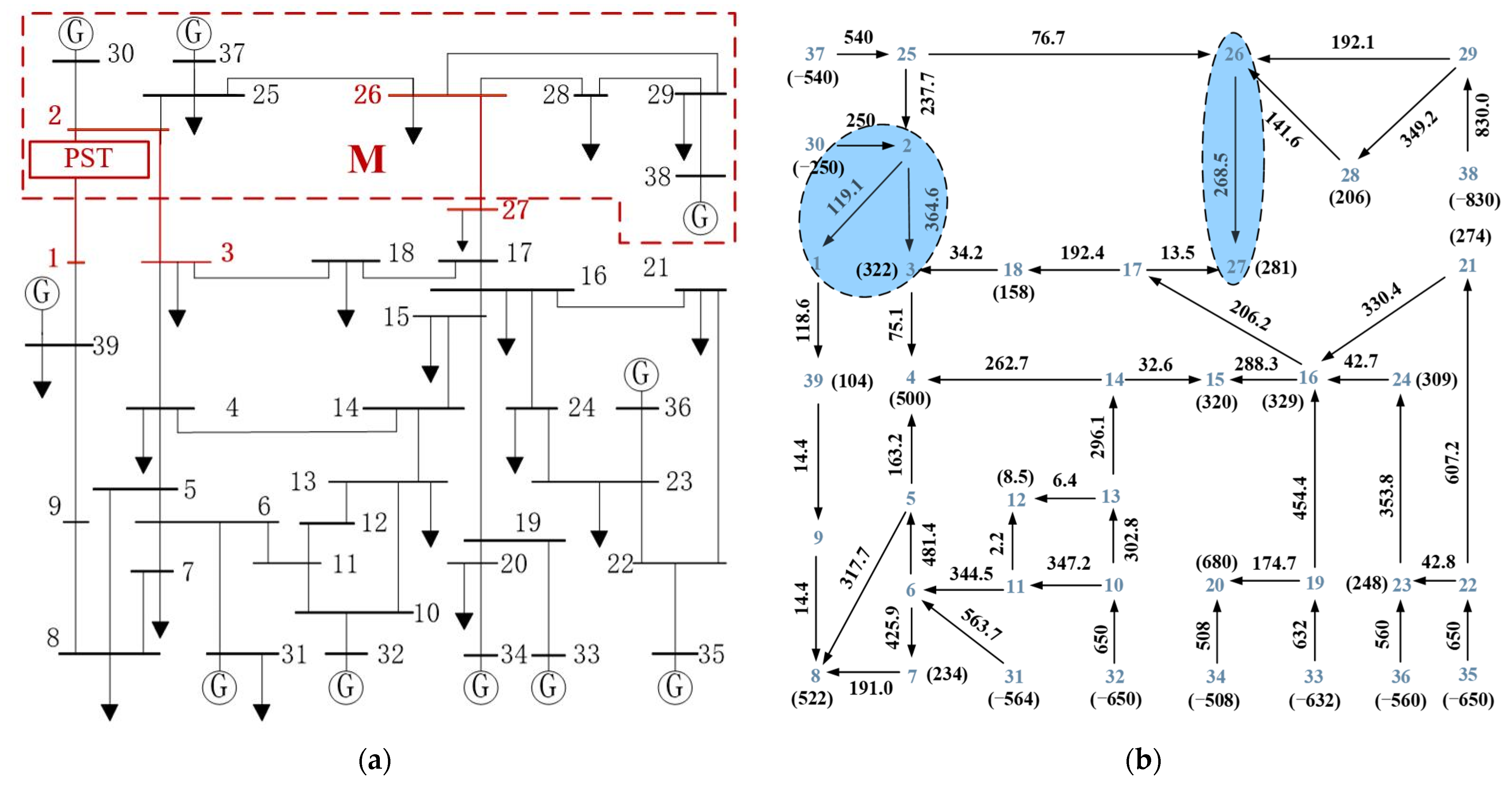
3. Multi-Node Network Power Flow Optimization Simulation

In BPA simulation software, IEEE 39-node standard power system is used to simulate and verify the regulation effect of double core symmetric PST on large-scale network power flow. The initial power flow distribution and PST installation position of the system are shown in Figure 8. As can be seen from Figure 8a, area “M” outputs electric energy to the lower area through transmission lines “2–1”, “2–3”, and “26–27”. Combined with Figure 8b, the active power transmitted along the three transmission lines are 119.1, 364.6, and 266.5 MW, respectively. Transmission lines 2–3 and 26–27 are heavy load, while line 2–1 is light load. The three transmission lines have the problem of uneven power flow distribution.
In this paper, PST is installed on transmission line “2–1” to transfer heavy load line power flow and improve power flow distribution. After the installation of PST, the active power flow of the three transmission lines “2–1”, “2–3”, and “26–27” was adjusted to 256.9, 254.3 and 240.3 MW, respectively. At this point, the maximum unbalance of active power on the three transmission lines is less than 8%, which verifies the power flow regulation function of PST, as shown in Figure 9.

4. Loop Network Power Flow Optimization Simulation

4.1. Design of 220 kV Phase Shifting Transformer Parameters

4.1.1. Loop Power Flow

Figure 10 shows the transmission line power flow of the 220 kV loop network of Huizhou–Sandong–Yongyuan of the Guangdong Power Grid. The transmission limit of the Huizhou–Yongyuan transmission line is restricted by the Huizhou–Sandong transmission line. When the load of The Huizhou–Sandong double circuit line is full, the load rate of the Huizhou–Yongyuan line is about 60%, and the transmission limit of the Huizhou–Sandong and Yongyuan section is 1305 MW. According to the research, PST can be installed at the head of Huizhou–Yongyuan line and the head of the Huizhou-Sandong line.

4.1.2. Parameters Design and Verification

High voltage power systems, transformers can easily generate direct current bias, which causes transformer iron core magnetic saturation. When the iron core was saturated, the magnetic sensing strength B tended to be fixed as the magnetic field strength increased. The inductivity of transformer primary winding is significantly reduced; the number of turns per volt of primary winding is higher than that of primary voltage, but the voltage of secondary winding does not increase, which may cause the transformer to burn out. The shift ratio of the PST saturated with the core is highly altered, and the output voltage and phase angle are greatly biased.
In order to avoid the magnetic saturation effect, the rated working point of the transformer is often designed near the saturation current. When the voltage rises to 1.1~1.2 pu, the transformer core will enter the saturation state. After the shape of the transformer core is determined, the voltage per turn of winding can be calculated, including
e t = 4.44 f B A t
where et is the electromotive force per turn of winding; f is the working frequency of the transformer; B is the peak value of magnetic flux density; At is the cross-sectional area of the iron core. Generally, in the design of transformer, B takes 1.7 T, which can be expressed as
{ f = 50   Hz e t = B A t 450 × 10 5
According to the rated voltage of the transformer, the number of turns of the winding can be determined so as to determine the level voltage of the excitation transformer. The parameters of the excitation transformer and series transformer designed in this paper are shown in Figure 11.
The equivalent impedance of PST is calculated using the PST model in Section 2.3. Considering leakage reactance, the equivalent impedance of PST varies from 7.15 Ω to 7.84 Ω with the change of phase shift angel. According to the demand of power flow regulation and considering the influence of leakage reactance of transformer, the parameters of 220 kV PST are calculated as shown in Table 2.
Considering the influence of the impedance of PST, simulation software is used to verify parameters of the designed PST. When the voltage at the head of line reaches the rated value, the line current and the output phase shift angle are measured, and the results are shown in Figure 12.
The simulation verifies that the phase shift angle at full load is 20°, and the internal phase shift angle is about 5°, which meets the performance requirements.

4.2. 220 kV Loop Network Power Flow Optimization Simulation

PSCAD software is used to simulate the actual line power flow, and the power flow regulation effect of PST on Guangdong 220 kV ring network under different working conditions is analyzed.

4.2.1. Steady Power Flow

After PST is installed, the transmission limit Pmax increases with the increase of phase shift angle θ, as shown in Figure 13.
From Figure 13, when PST is installed on the Double-loop line of the Huizhou–Sandong, the transmission limit of Huizhou–Sandong and Huizhou–Yongyuan section reaches 1645 MW when θ = 8°, and the load rates of the four transmission channels (the Huizhou–Sandong double-loop line and the Hui–Yongyuan double-loop line) are close to 100%.
When PST is installed on the Huizhou–Yongyuan double loop line, the transmission limit of the section reaches 1645 MW when the phase shift angle θ = 10°. The transmission and distribution capacity of the existing network topology is significantly improved by PST installation.

4.2.2. N-1 Power Flow

Considering the occurrence of extreme cases, the disconnection of Huizhou–Sandong B Line and Huizhou–Yongyuan B Line is considered respectively, as shown in Figure 14.
From Figure 14, when PST is installed on Hui–Sandong A line, the transmission limit of the Huizhou–Sandongjia and Huizhou–Yongyuan sections reaches 1219 MW when θ = 8°, and the load of the three transmission channels (The Huizhou–Sandong A line and the Huizhou–Yongyuan double loop line) are close to full. When the PST is installed on the Line A of Huizhou–Yongyuan, the transmission limit of the section reaches 1219 MW when θ = 9°.
The transect transmission capacity can be improved by installing phase shifting transformer at the head of Huizhou–Yongyuan line or the head of Huizhou–Sandong line. Considering that the phase shift angle and rated current required to adjust the power flow are smaller when PST is installed on the Huizhou–Sandong line, the capacity of PST can be designed smaller. Therefore, we choose to install PST on the Huizhou–Sandong double-loop line.

4.3. Simulation Analysis under Short Circuit Fault

Based on PSCAD simulation software, a 220 kV voltage level constant load model is built. Explore the influence of PST on the system short-circuit current under the condition of short-circuit fault, and the influence of fault on the output phase shift angle of PST.
Single phase short circuit occurs most frequently in a high voltage system, generally accounting for about 70%. It is set that phase a grounding short circuit fault occurs in the system at 0.3 s, and the fault is removed at 0.4 s. The line short-circuit current with and without PST is shown in Figure 15.
It can be seen from Figure 15 that after installing the phase shifting transformer, the short-circuit current value at the head end of the system decreases slightly. When the PST is not installed, the peak value of the short-circuit current of the system is 16.66 kA. After installing the PST, the peak value of the short-circuit current is 16.39 kA. This is because the leakage reactance of the series transformer and excitation transformer windings make the PST show a certain short-circuit impedance when the system fails. To some extent, it limits the size of short-circuit current.
In this case, the phase shift angle of PST output is shown in Figure 16.
As can be seen from Figure 16, in case of phase a grounding fault, the phase shift angle of PST output will increase by an angle. This is because when phase a grounding short circuit occurs, the voltage of phase a decreases, and the voltage of lines B and C increases. This voltage is injected into the excitation transformer, passes through the excitation transformer and series transformer, and finally forms the phase a compensation voltage. Therefore, the phase a compensation voltage increases. The phase shift angle of PST output also increases.

5. Economic Analysis of Engineering Application

5.1. Cost of PST Analysis

Taking the parameters of 220 kV PST as an example, the total price of PST is defined as CPST, and the unit is ten thousand yuan, while the cost of series transformer is CST, and the unit is ten thousand yuan. The total capacity of series transformer is VST, and the unit is MVA. The unit capacity cost of series transformer is dST, and the unit is ten thousand yuan/MVA. The cost of the excitation transformer is CET. The total capacity of the excitation transformer is VET. The unit capacity cost of the excitation transformer is dET. The cost of the on-load voltage regulator switch is CR. The total capacity of the on-load voltage regulator switch is VRS. The unit capacity cost of the on-load voltage regulator switch is dRS. The total cost of the PST is shown in (9):
C PST = C ST + C ET + C RS
The cost of each major component can be expressed as
{ C ST = V ST × d ST C ET = V ET × d ET C RS = V RS × d RS
According to Equations (9) and (10) above, the solution matrices of the total PST cost CPST of component capacity VET, VST, and VRS and unit capacity cost dET, dST, and dRS can be established, as shown in Equation (11):
C PST = [ V ST , V ET , V RS ] [ d ST d ET d RS ]
According to the investigation and inquiry made to the on-load voltage regulating switch plant, the unit cost of the mechanical on-load voltage regulating switch dRS is 13,600 yuan/MVA. According to the contract cost of 350 MVA/230 kV PST provided by Tianwei Protection Transformer Company for Northwest Energy Company of the United States, if the traditional mechanical voltage regulating method is adopted, including switch and construction cost of about 120,000 yuan/MVA, the annual operating cost is about 5000 yuan/MVA. Therefore, the cost of PST can be counted as 125,000 yuan/MVA. Excluding the switch cost, the unit cost of the transformer, dST and dET, is about 110,000 yuan/MVA. According to the technical parameters calculated in Table 2, VRS is 219 MVA, VST is 224 MVA, and VET is 219 MVA. Therefore, the cost CPST of a single PST in the Huizhou triangle ring network is about 51.7 million yuan, of which CRS is about 2.98 million yuan.

5.2. Comparative Analysis of UPFC and PST Costs

The topology of UPFC (unified power flow controller) is shown in Figure 17. It is mainly composed of three main modules: series transformer (TSeries), parallel transformer (TShunt), and MMC (VSC1 and VSC2). UPFC is the most comprehensive facts device, including all the capabilities of voltage regulation, series compensation, and phase shifting control.
UPFC can simultaneously and quickly control the active power and reactive power in the transmission line [32,33]. After power grid failure, UPFC can quickly and independently control the active and reactive power compensation of the wind power system and maintain the voltage stability of grid points by providing reactive power support so as to improve the low-voltage ride through capacity of wind turbines.
The total price of UPFC is defined as CUPFC. The cost of MMC is quite high due to the adoption of a large number of power electronic devices and the consideration of voltage and heat dissipation.
The cost of series transformer is CST-UPFC, and the unit is ten thousand yuan. The total capacity of series transformer is VST-UPFC. The unit capacity cost of series transformer is dST-UPFC. The cost of the parallel transformer is CPT-UPFC. The total capacity of the parallel transformer is VPT-UPFC. The unit capacity cost of the parallel transformer is dPT-UPFC. The cost of MMC is CMMC. The total capacity of MMC is VMMC. The cost of unit capacity of MMC is dMMC. Then the total cost of UPFC can be expressed as
C UPFC = C ST-UPFC + C PT-UPFC + C RS-UPFC
The cost of each major component can be expressed as
{ C ST , UPFC = V ST , UPFC × d ST , UPFC C PT , UPFC = V PT , UPFC × d PT , UPFC C MMC = V MMC × d MMC
Based on Equations (12) and (13) above, the solution matrix of CPST of total PST cost regarding component capacity VPT-UPFC, VST-UPFC, and VMMC and unit capacity cost dPT-UPFC, dST-UPFC, and dMMC can be established, as shown in Equation (12).
C UPFC = [ V ST-UPFC , V ET-UPFC , V MMC ] [ d ST-UPFC d PT-UPFC d MMC ]
According to the UPFC engineering application of Suzhou Power Grid and the UPFC engineering case of Northwest China power grid DOJ-XL line in [26], the engineering cost of setting up UPFC of 330 kV voltage grade line with a primary transmission capacity of 680 MW on the DOJ-XL line is 158.29 million yuan. The cost of a single UPFC used in the Huizhou triangle ring network is estimated at 103.12 million yuan, out of which the serial transformer CST-UPFC is 24.66 million yuan. The cost of the parallel transformer CPT-UPFC is 24.16 million yuan, and the total cost CMMC is 49 million yuan.
According to the above analysis, the cost comparison between 220 kV PST and UPFC is shown in Table 3 below. The total cost of a single PST decreases by 49.86% compared with UPFC. For economic reasons, PST is more suitable for engineering applications.

6. Experimental Verification

On the basis of theoretical analysis and simulation verification, a 380 V (±4 gear) prototype is designed and manufactured for experimental verification of its power flow regulation performance. The experimental schematic diagram is shown in Figure 18. The three-phase power line used in the experiment platform has a voltage of 380 V and a frequency of 50 Hz. The three-phase power supply is adjusted by a voltage regulator of 220 V/(0~430)V to obtain the system’s head voltage of 220 V phase voltage.
In this experiment, the voltage at both ends of the system is the same. In the absence of PST, there is no phase difference between the first and the end of the system, the line current is 0, and the active power and reactive power flow are 0. The experimental wiring diagram is shown in Figure 19, and the experimental results are shown in Table 4.
In Table 4, Us is the voltage before the phase shift, UL is the voltage after the phase shift, and θ represents the phase difference before and after phase shifting; θPST represents the phase angle of the output voltage of the PST. P is the active power transmitted by the line.
The variation of line transmission power with the phase shift angle of PST output is shown in Figure 20. We can conclude from the experimental results that the designed PST phase shift angle ranges from −25.5° to 26.17°. The adjustment range of P is −224.12 W~240.17 W by changing the angle of phase shift.
By comparing the above experimental data with the theoretical values, the following conclusions can be drawn:
(1)
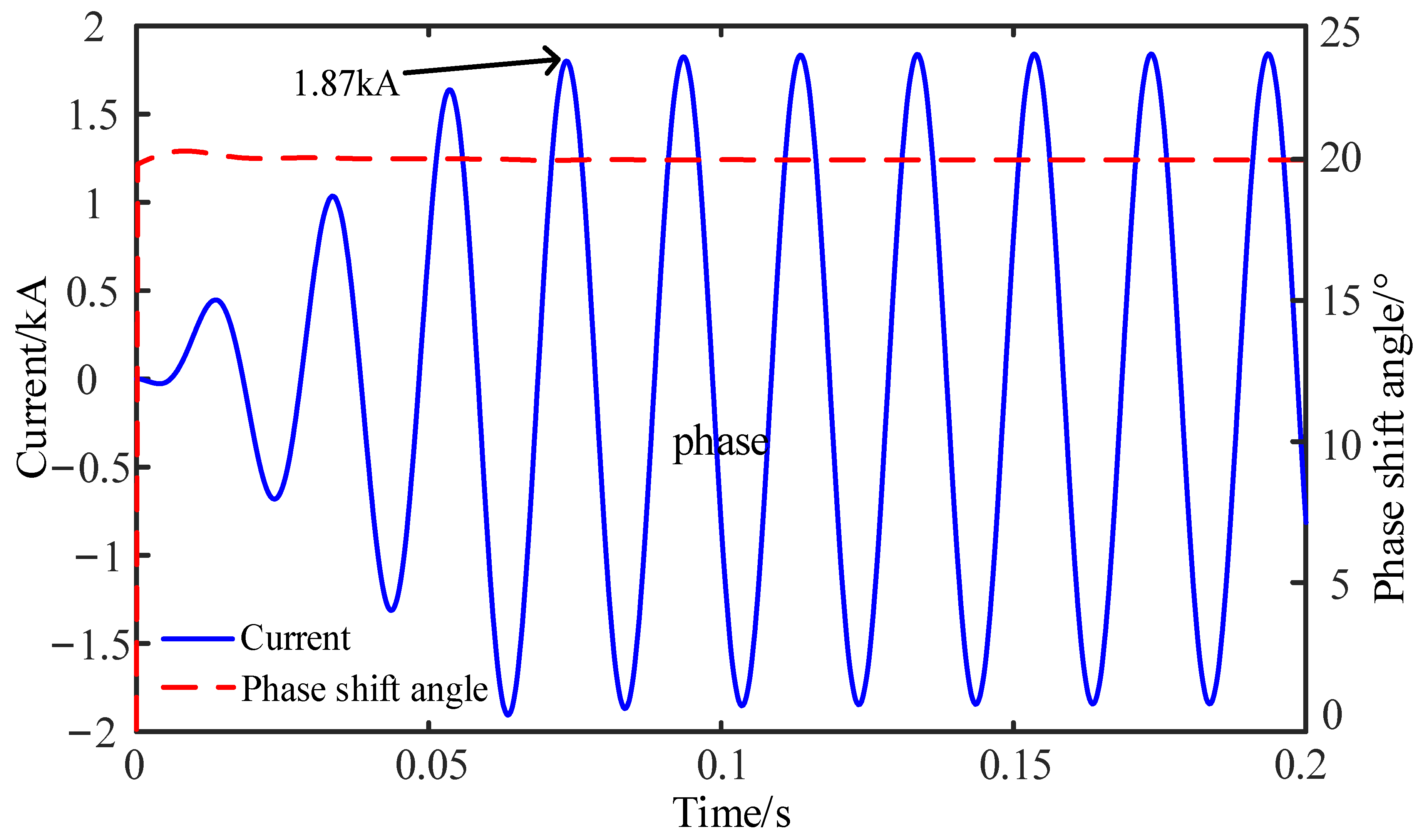
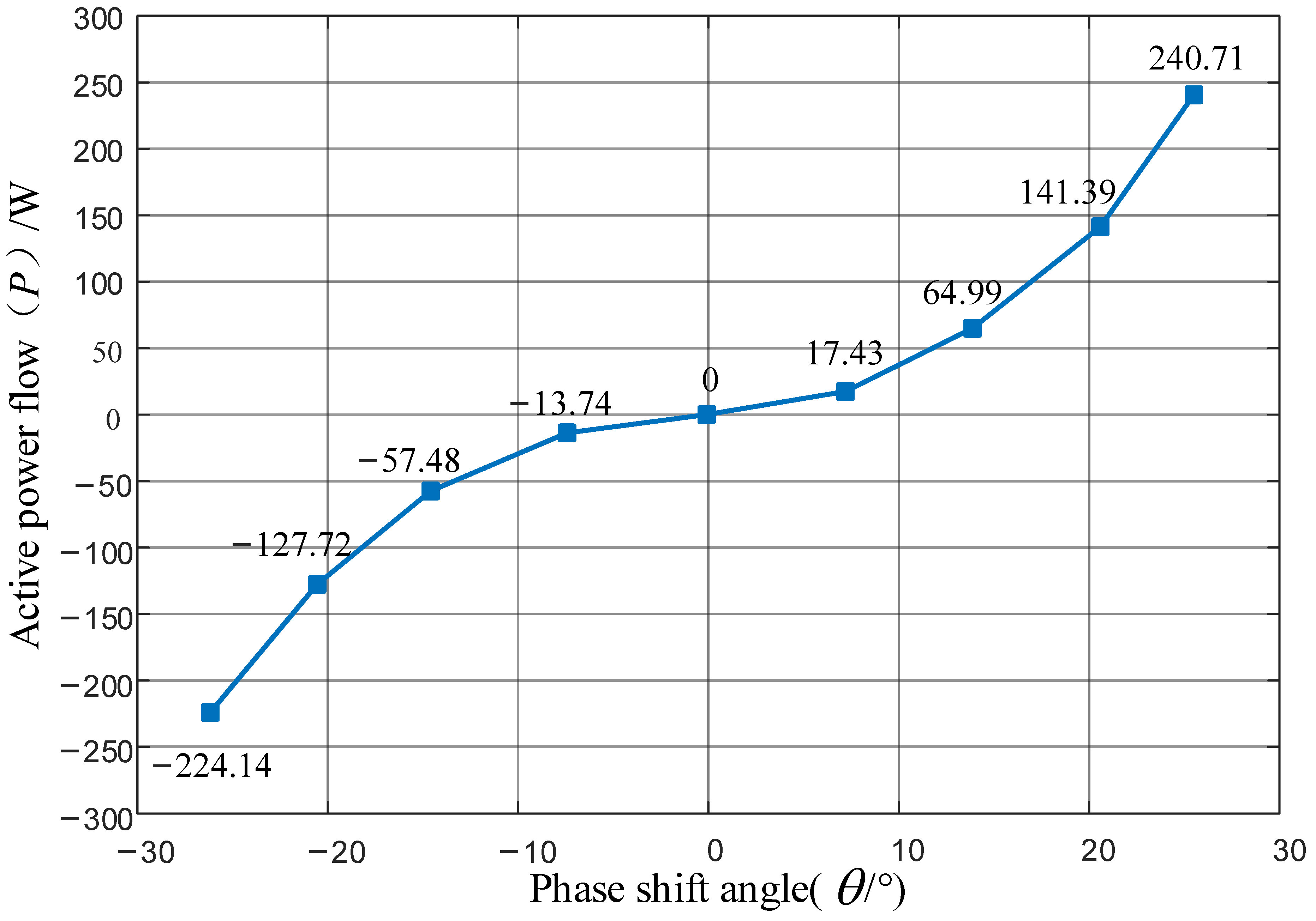
When the PST is switched to +4 gear, the maximum leading phase shift angle is output, and the angle is −25.5°. When the PST is switched to −4, the maximum lag phase shift angle is output, and the angle is 26.17°. The error between the measured value and the theoretical value of each gear is small, and the reason for the error is the leakage reactance of transformer winding.
(2)
With the change of phase shift angle, the adjustment range of line transmission power is −224.12 W~240.17 W. When the on-load voltage regulating switch of the PST is turned to different gears, the active power of the line can be adjusted without changing the voltage amplitude before and after the phase shift, and thus, we can realize the independent control of the active power of the line.

7. Conclusions

In this paper, the working principle, topological structure, selection research, mathematical model, power flow control function, and economic analysis of high voltage phase shift transformer were studied, and the following conclusions were drawn:
(1)
Comparing the characteristics of various types of PST, a high voltage of 220 kV and above was more suitable for the selection of double core symmetrical PST. The influence of winding leakage reactance and saturation effect should be considered in the design of PST parameters; the iron core area and winding turns should be reasonably selected, and a certain phase shifting angle margin should be reserved.
(2)
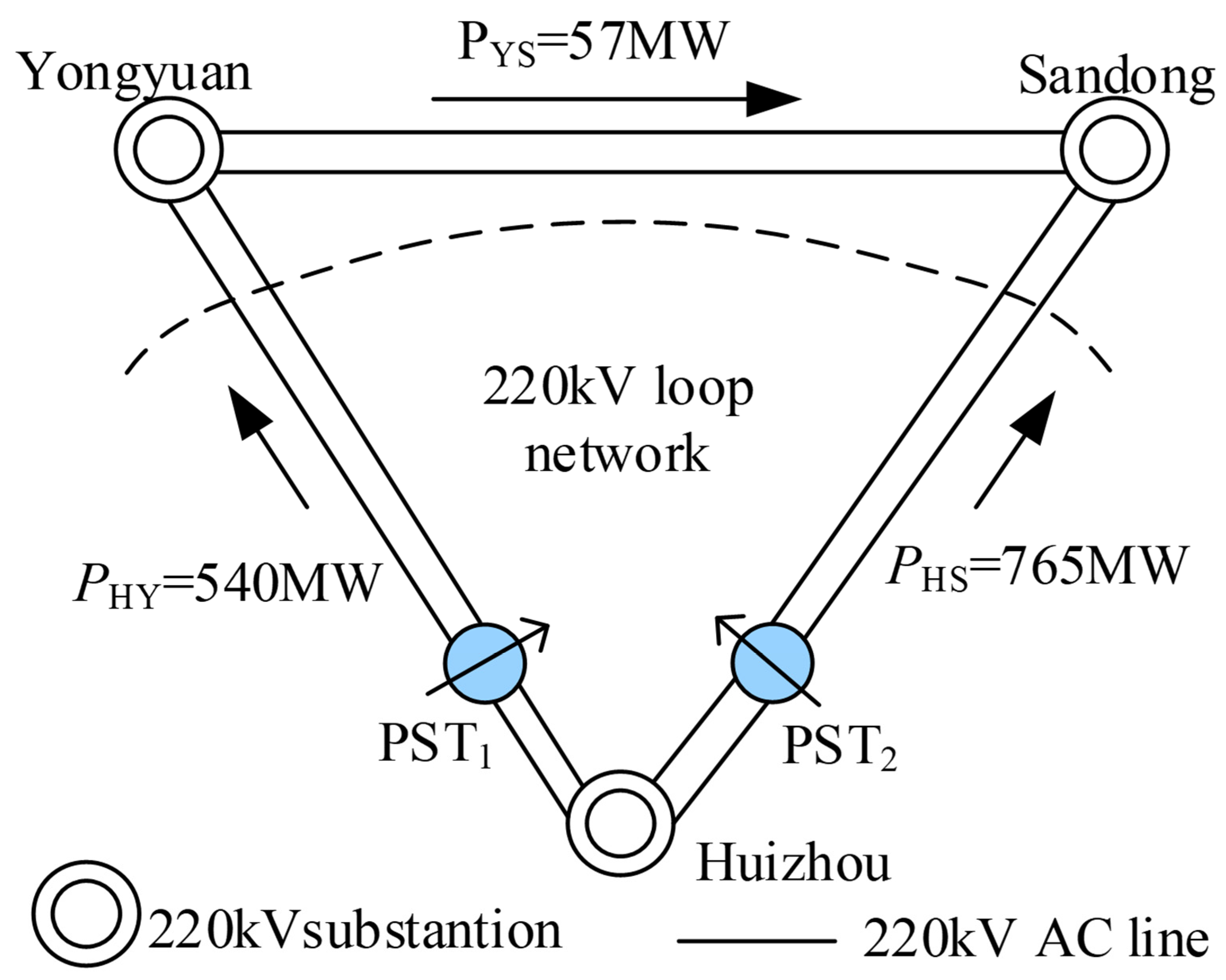
For the actual 220 kV ring network of the Guangdong Power Grid, when PST was installed in the Huizhou–Sandong line and Huizhou–Yongyuan line, the transmission limit of the two lines sections could be increased to 1645 MW under normal working conditions, and the load rate of the four transmission channels was close to 100%. The transmission limit of both lines and planes could be increased to 1219 MW under N−1 condition. However, the phase shift angle required to adjust the power flow was smaller (θ = 8°), and the cost was lower when it was installed on the Huizhou–Third line. Therefore, the installation site chosen was the Huizhou–Sandong line.
(3)
As FACTS elements, UPFC had faster response speed and stronger power flow regulation ability than PST and could provide reactive power compensation for the system, with certain low−voltage ride through capability. However, PST had simple structure and better economy and reliability. In the 220 kV ring network scheme, the total cost of a single PST was reduced by about 49.86%. On the premise of ensuring the effect of power flow regulation, the investment cost was significantly reduced, and the economic benefit was remarkable.
(4)
Through the prototype experiment, the regulation ability of dual core symmetrical PST to line power flow was verified, and the controllable regulation of line power flow was realized on the premise of constant voltage amplitude. However, due to the influence of measurement error and background harmonic, there were some errors in the experimental results. This paper did not consider the switching process and transient regulation performance of PST, so it was only suitable for steady−state power flow analysis. If the transient performance needed to be analyzed, it would be necessary to do further research in combination with power electronic devices.

Author Contributions

Conceptualization, M.Y.; methodology, J.Y.; validation, J.Y.; formal analysis, W.Z.; investigation, X.Y.; data curation, S.X.; writing—original draft preparation, M.Y.; writing—review and editing, W.Z. and J.M.; visualization, W.Z.; supervision, J.Y.; project administration, F.L. and M.Y.; funding acquisition, Z.L. All authors have read and agreed to the published version of the manuscript.

Funding

This research and the APC were funded by China Southern Power Grid Corporation’s science and technology project “Research and demonstration application of key technologies of economic power grid power flow controller based on controllable phase shifter”, grant number 037700KK52190009.

Institutional Review Board Statement

Not applicable.

Informed Consent Statement

Not applicable.

Data Availability Statement

Not applicable.

Conflicts of Interest

The authors declare no conflict of interest.

References

  1. Song, T.; Yi, L.; Rui, Z. Study on optimal allocation of waste mine pumping and storage power station based on high proportion of renewable energy. Power Eng. Eng. Technol. 2020, 39, 87–95. [Google Scholar]
  2. Belivanis, M.; Bell, K.R.W. Coordination of phase shifting transformers to improve transmission network utilization. In Proceedings of the 2010 IEEE PES Innovative Smart Grid Technologies Conference Europe (ISGT Europe), Gothenburg, Sweden, 11–13 October 2010; pp. 1–6. [Google Scholar]
  3. Jinxing, W.; Qing, L. Transmission control technology of large power grid new energy system with UPFC. Electr. Meas. Instrum. 2018, 55, 51–57. [Google Scholar]
  4. Rong, R.; Zirong, Z.; Zhinong, W. Multi−stage and Multi−Objective Reactive Power Optimization Algorithm of power system considering UPFC. Power Eng. Technol. 2020, 39, 76–85. [Google Scholar]
  5. Hussain, S.; Yang, X.; Aslam, M.K.; Shaheen, A.; Javed, M.S.; Aslam, N.; Aslam, B.; Liu, G.; Qiao, G. Robust TiN nanoparticles polysulfide anchor for Li–S storage and diffusion pathways using first principle calculations. Chem. Eng. J. 2020, 391, 123595. [Google Scholar] [CrossRef]
  6. Wang, L.; Wang, Z.; Li, H. Asymmetrical Duty Cycle Control and Decoupled Power Flow Design of a Three−port Bidirectional DC−DC Converter for Fuel Cell Vehicle Application. IEEE Trans. Power Electron. 2019, 27, 891–904. [Google Scholar] [CrossRef]
  7. Munisamy, V.; Sundarajan, R.S. Hybrid technique for load frequency control of renewable energy sources with unified power flow controller and energy storage integration. Int. J. Energy Res. 2021, 45, 17834–17857. [Google Scholar] [CrossRef]
  8. Zhou, L.; Swain, A.; Ukil, A. Reinforcement learning controllers for enhancement of low voltage ride through capability in hybrid power systems. IEEE Trans. Ind. Inform. 2019, 16, 5023–5031. [Google Scholar] [CrossRef]
  9. Walter, S. Phase Shifting Transformers Discussion of Specific Characteristics; CIGRE: Paris, France, 1998; pp. 12–306. [Google Scholar]
  10. Wang, Q.; Zhu, X.; Chen, Y.F. A Novel Zinc Oxide Sensor: Application for Transformer Fault Diagnosis. J. Nanoelectron. Optoelectron. 2018, 13, 1789–1792. [Google Scholar] [CrossRef]
  11. Qiu, H.; Jiang, C.; Li, G.; Hao, D.; Yu, X.; Sun, Y. Design of the Voltage Transformer Based on Nanocrystalline Alloys and Its Application in Intelligent Detection of Secondary Polarity. J. Nanoelectron. Optoelectron. 2021, 16, 1501–1509. [Google Scholar] [CrossRef]
  12. Zhiwei, C.; Zhiwei, L.; Wenping, L. Brief discussion on design of large power phase shifting transformer. Transformer 2014, 51, 1–4. (In Chinese) [Google Scholar]
  13. Siddiqui, A.S.; Khan, S.; Ahsan, S.; Khan, M.I.; Annamalai. Application of phase shifting transformer in Indian Network. In Proceedings of the International Conference on Green Technologies, Trivandrum, India, 18–20 December 2012; pp. 186–191. [Google Scholar]
  14. Zenghui, Y.; Yong, C.; Dechang, W. Classification phase shifting transformer control strategy research. East China Electr. Power 2013, 41, 2233–2236. [Google Scholar]
  15. Hou, C.H.; Dai, C.B.; Sun, Y. Status quo and feature of thyristor controlled phase shifting transformer. Smart Grid 2014, 2, 18–20. (In Chinese) [Google Scholar]
  16. Enrico, M.C.; Gabriele, M.; Dietrich, B. Power Flow Control on the Italian Network by Means of Phase Shifting Transformers; A2–206; CIGRE: Paris, France, 2006. [Google Scholar]
  17. Khan, U. Modeling and Protection of Phase Shifting Transformers; University of Western Ontario: Ontario, ON, Canada, 2013. [Google Scholar]
  18. Li, D.; Ding, J.; Wang, Z.F.; Dai, C.C.; Song, Y.T.; Shen, X.H. The research situation and engineering application of phase shifting transformer. Smart Grid 2015, 7, 9. [Google Scholar]
  19. Liexin, W.U.; Mengze, Y.U.; Zuohong, L.I. Electromagnetic unified power flow controller and its application in loop power flow regulation. High Volt. Technol. 2018, 44, 3241–3249. [Google Scholar]
  20. Qun, L.; Ningyu, Z.; Shan, G. RTDS modeling and application scenario analysis of power grid phase shifting transformer. Power Eng. Technol. 2021, 40, 53–58. [Google Scholar]
  21. Heng, C. Steady State Analysis of Power System; China Electric Power Press: Beijing, China, 2007; pp. 104–110. [Google Scholar]
  22. Verboomen, J.; Van Hertem, D.; Schavemaker, P.H.; Kling, W.L.; Belmans, R. Phase shifting transformers: Principles and applications. In Proceedings of the International Conference on Future Power Systems, Amsterdam, The Netherlands, 6 March 2006; pp. 1–6. [Google Scholar]
  23. Yu, J.L.; Zhuo, L.; Zhang, K.; Feng, J. Treatment of longitudinal and transversal regulations in power flow calculation. Autom. Electr. Power Syst. 1992, 5, 31–33. (In Chinese) [Google Scholar]
  24. Liguo, Z. Research on Key Technologies of 220kV Phase Shift Transformer; Shandong University: Shandong, China, 2016. [Google Scholar]
  25. Jiying, Z. Electric Field Calculation and Analysis of High Voltage and Large Capacity Single Core Phase Shifting Transformer; North China Electric Power University: Beijing, China, 2015. [Google Scholar]
  26. Yong, C.; Yinghui, Y.; Zenghui, Y. Ultra−high voltage grid and controllable phase shifting transformer demonstration engineering project evaluation. East China Electr. Power 2013, 41, 2237–2240. [Google Scholar]
  27. Jie, M.; Chunding, G.; Yinghui, Y. Application of phase shifting transformer technology to EHV power grid. East China Electr. Power 2013, 41, 2066–2067. [Google Scholar]
  28. Fei, G.; Xin, L.; Litong, W. Study on calculation method of maximum stage voltage of on load tap changer of symmetrical double core phase shifting transformer. Chin. J. Electr. Eng. 2017, 37, 2110–2119. [Google Scholar]
  29. Yinghao, Z.; Dazhong, S. Electrical Mechanism of on−Load Tap Changer; China Electric Power Press: Beijing, China, 2011. [Google Scholar]
  30. Litong, W. Research on Key Problems of Hybrid on Load Tap Changer in Phase Shifting Transformer; North China Electric Power University: Bejing, China, 2017. [Google Scholar]
  31. Xin, L.; Guishu, L.; Litong, W. Determination method of technical parameters of on load tap changer in double core phase shifting transformer. High Volt. Technol. 2017, 43, 838–844. [Google Scholar]
  32. Parvathy, S.; Thampatty, K. Dynamic modeling and control of UPFC for power flow control. Procedia Technol. 2015, 21, 581–588. [Google Scholar] [CrossRef] [Green Version]
  33. Rajabi−Ghahnavieh, A.; Fotuhi−Firuzabad, M.; Shahidehpour, M.; Feuillet, R. UPFC for enhancing power system reliability. IEEE Trans. Power Deliv. 2010, 25, 2881–2890. [Google Scholar] [CrossRef]
Figure 1. Equivalent model of PST in transmission line.
Energies 15 02363 g001
Figure 2. Workflow of the load flow optimization with PST.
Energies 15 02363 g002
Figure 3. Various types of PST topology: (a) Single core asymmetric type, (b) Single core symmetrical type, (c) Two core asymmetric type, and (d) Double core symmetrical type.
Energies 15 02363 g003
Figure 4. Voltage phasor of PST. (a) The asymmetric PST, (b) Symmetric PST.
Energies 15 02363 g004
Figure 5. Topological structure of double core symmetrical.
Energies 15 02363 g005
Figure 6. Equivalent circuit of two core symmetrical PST.
Energies 15 02363 g006
Figure 7. Phasor relation considering internal impedance.
Energies 15 02363 g007
Figure 8. Initial power flow of IEEE39 nodes. (a) PST location diagram, (b) Initial power flow distribution diagram.
Energies 15 02363 g008
Figure 9. Power flow distribution after installing PST.
Energies 15 02363 g009
Figure 10. 220 kV transmission lines and PST location.
Energies 15 02363 g010
Figure 11. Parameters of the excitation transformer and series transformer. (a) Series transformer, (b) Excitation transformer.
Energies 15 02363 g011
Figure 12. Performance verification of PST.
Energies 15 02363 g012
Figure 13. Transmission limit of 220 kV network.
Energies 15 02363 g013
Figure 14. Transmission limit of 220 kV ring network in case of N-1.
Energies 15 02363 g014
Figure 15. Single phase grounding fault phase current.
Energies 15 02363 g015
Figure 16. Phase shift angle under single phase grounding.
Energies 15 02363 g016
Figure 17. Schematic diagram of UPFC.
Energies 15 02363 g017
Figure 18. Experimental schematic diagram.
Energies 15 02363 g018
Figure 19. Experimental wiring diagram.
Energies 15 02363 g019
Figure 20. Relationship between line active power flow and phase shift angle.
Energies 15 02363 g020
Table 1. Comparison of single core PST and double core PST.
PerformanceSingle Core PSTDouble Core PST
StructureSimpleComplex
On-load tap switchHigh insulation requirementsLow insulation requirements
Short circuit impedance<10%12~19%
Applicable voltage classLowHigh
CostLowHigh
The phase shift rangeNarrowWide
Table 2. Technical parameters of 220 kV PST.
Technical ParametersValue
Rated voltage/kV230
Rated current/kA1.3
Rated capacity/MVA450
Adjustment class±13
No-load phase shift Angle/°25
Full-load phase shift Angle/°20
Short circuit impedance of series transformer/%7
Short circuit impedance of excitation transformer/%4.5
Table 3. Cost comparison between 220 kV PST and UPFC.
Cost of Each UnitTotal Cost
UPFC10.312 million yuan206 million yuan
PST5.170 million yuan129 million yuan
PST compared with UPFCReduced by 49.86%Reduced by 49.86%
Table 4. Experimental test results.
GearUs (V)UL (V)θ (°)θPST (°)P (W)
TheoreticalMeasuredTheoreticalMeasured
12242236.27.293.193.617.43
222422312.413.996.297.264.99
322322318.720.699.4100.3141.39
422322225.025.5102.5102.6240.71
022322300//0
−1223223−6.2−7.4−93.1−93.6−13.74
−2223223−12.4−14.6−96.2−96.4−57.48
−3223223−18.7−20.6−99.4−100.8−127.72
−4223223−25.0−26.1−102.5−103.5−224.12
Publisher’s Note: MDPI stays neutral with regard to jurisdictional claims in published maps and institutional affiliations.

