1. Introduction
The UK Hydrogen Strategy was released in 2021, whereby it outlines the vision for the UK and how it envisions hydrogen to be a versatile replacement for high-carbon fuels. Hydrogen offers the opportunity for a reduction in emissions in UK industrial sectors and to provide flexible energy for power, heat, and transport [
1]. With regards to hydrogen, the current UK demand is 27 TWh, predicted to rise to 460 TWh by 2050 [
1], with the push for almost all of it to come from low-carbon and clean energy sources.
Most of hydrogen made today comes from steam reforming of natural gas or coal gasification, which contribute significant emissions to the atmosphere. For hydrogen to play a significant role in decarbonising the UK economy, all current and future production methods will need to be low- or zero-carbon.
Increasing hydrogen supply whilst significantly reducing emissions requires a radical approach. There are numerous production methods for hydrogen, which include steam-methane reforming, electrolysis, bioenergy carbon capture and storage, thermochemical water splitting, and hydrogen pyrolysis. One clean form of scaling up supply is through thermochemical water splitting using a high-temperature heat from advanced modular nuclear power plants (NPPs). The work presented herein investigates the possibility of meeting the temperature requirements for hydrogen production using in-house tools to assess the NPP and the control-system design for the offtake of hot gas.
2. Thermochemical Processes
The thermochemical process involves splitting water molecules via a repetitive route consisting of intermediate reactions, aided by numerous reactive species. Thus, the overall chemical reaction is the equivalent to the energy required for the dissociation process [
2]. It requires thermal energy, thereby restricting all requirements associated to the catalyst and other consumables, with water being the only tangible consumable, and everything else being recycled. Typical temperatures range from 500–1800 °C, with no requirement for electricity in most cases, and does not involve electrolysis or the requirement of a separation membrane. The step-cycle processes of thermochemical splitting have been comprehensively reviewed by [
2,
3,
4,
5,
6,
7].
As an energy carrier, thermochemical cycles are suitable and benign as methods for hydrogen production [
8]. The sulphur–iodine (s–i) cycle is one such cycle and was initially introduced by General Atomics in 1970 [
8], and has since undergone numerous improvements. One benefit of the s–i cycle is that it has the added value to scale up production and cope with high-temperature production, with a temperature requirement of ~800 °C [
9]. Other cycles reviewed by [
8] included zinc–sulphur–iodine, which was a recently developed cycle from s–i but with more complex reactions. Its temperature is very well-dependent on the reactants; There is the copper–chlorine cycle, which has a maximum reaction temperature of 530 °C, which makes it easy to integrate with low-grade heat-numerous sources [
10], including nuclear. However, it has problems, such as deposition and low heat and mass-transfer decrease, including separation problems at high temperature; The magnesium–chlorine cycle is a promising cycle with desirable energy and exergy qualities. It has a lower temperature requirement, which makes it desirable to integrate numerous energy sources, but it also has a high temperature requirement at 800 °C, which results in yielding corrosion within the species. The reaction of products at the first reaction and the high potential required due to the aqueous nature of hydrochloric acid in the second reaction makes it a challenging cycle and reduces potential for scaling; With regard to the vanadium–chlorine cycle, this was reviewed and was found to have high energy and exergy efficiencies, but requires further development of the thermodynamic process regarding the vanadium oxide. It also experiences low yield of the reverse Deacon reaction. There is also a requirement to further develop the entire process by advancing technologies; Another cycle, the iron–chlorine cycle, is also promising, with inexpensive chemicals and vast knowledge of the chemical species of iron oxides and chlorides. However, it suffers from low efficiency, heat management, formation of Fe
2Cl
6, and low yield of reverse Deacon reaction. The step-cycle processes of thermochemical splitting have been comprehensively reviewed by [
2], with the s–i cycle showing better specific output in comparison to other cycles at scale, and modest efficiencies, notwithstanding the minimum temperature requirement. As such, the minimum temperature requirement forms part of the requirement that the NPP should meet when it comes to selecting a viable thermochemical method, based on the working fluid temperature from the reactor.
3. Nuclear Power Plant Design Scenarios
The future of nuclear power will depend partly on its ability to compete effectively with other low-carbon electricity sources. One advantage the nuclear plant has over other low-carbon technologies is the continuous, reliable base-load supply to ensure demand is always met.
Different design scenarios are applicable to delivering clean, safe, and affordable energy with nuclear. The scenarios could either be in the reactor type, to the energy conversion system using different working fluids as coolant in a Brayton or Rankine cycle configuration. One could choose reactors ranging from PWRs to GFR within the Generation III and IV framework to meet specific design requirements. These reactors could drive the different energy-conversion arrangements to meet electricity and non-electricity needs.
The nuclear reactors could be further classified into small modular reactors (SMRs) and large nuclear power plants (LNPPs). SMRs have been defined by the International Atomic Energy Agency (IAEA) as “newer generation reactors designed to generate electric power typically up to 300 MWe, whose components and the system can be shop fabricated and then transported as modules to the sites for installation as demand arises” [
11]. LNPPs consist of reactors above 300 MWe capacity. Smaller designs are offered alongside large nuclear reactors to diverse utility requirements. Nuclear reactors of both kinds (small modular and large) are likely to differ in their overnight, financing, and variable costs [
12]. Construction cost significantly drives the total cost of any nuclear project; hence, SMRs offer smaller total project costs compared with LNPPs. Unlike smaller reactors, big reactors such as Hinkley Point C incorporate technological lessons learned over the last 60 years. As a result of their size, they require multibillion-dollar investments and a decade or more of construction time, putting them at risk of budget overruns and delays. SMRs provide better options for load-following because of their size. It is easier and more flexible to operate the primary circuit at full capacity and switch the thermal power for cogeneration [
13].
In the last few years, there has been a considerable interest in using closed-cycle gas-turbine technology for SMR or LNPP energy conversion due to (a) its easy adaptability, (b) flexibility to change working fluid, (c) high efficiency of electricity generation at part load, (d) high level of availability, and (e) low initial capital and maintenance cost when compared with Rankine cycles.
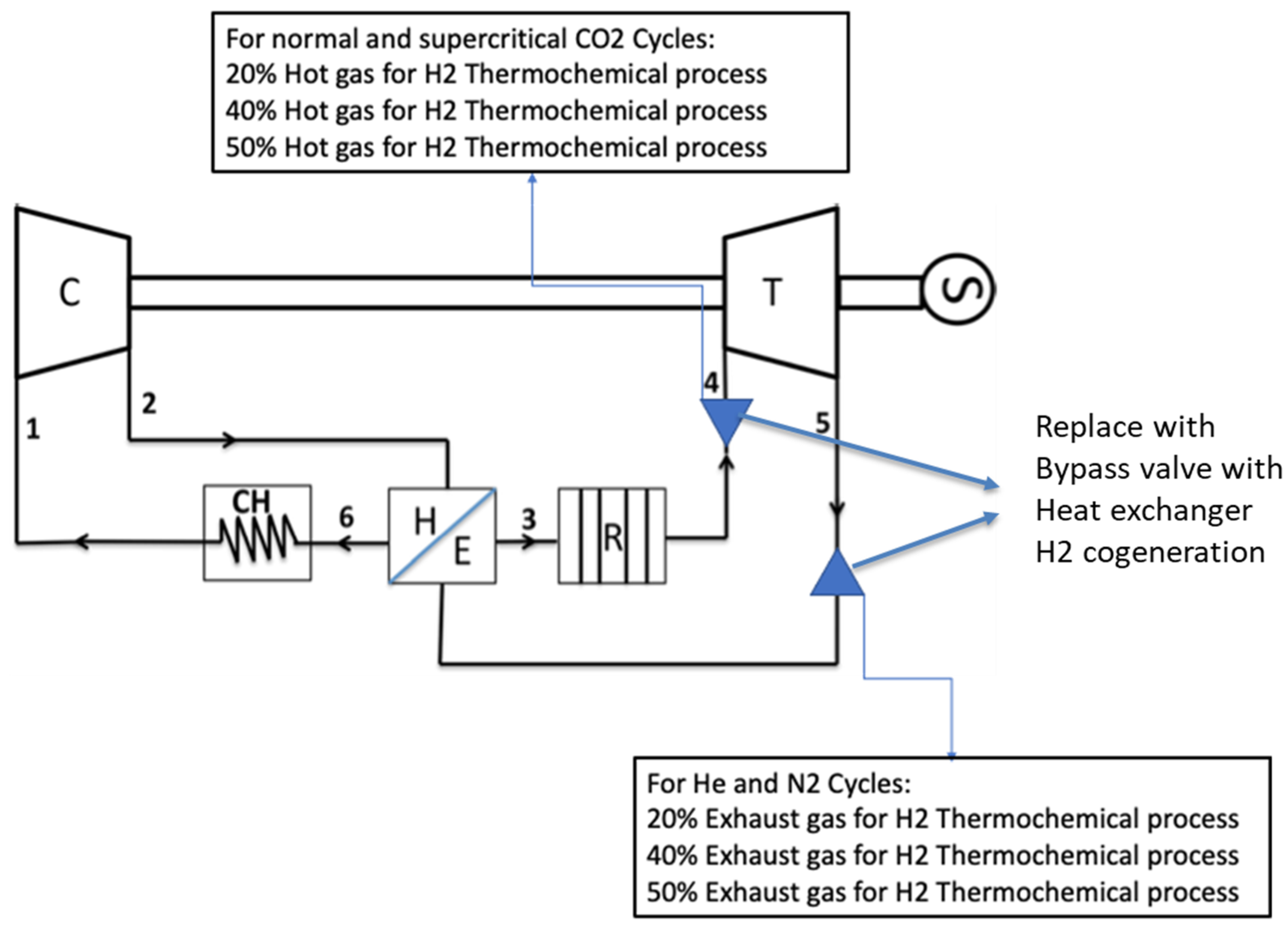
Figure 1 describes a typical schematic of a high-temperature gas-cooled reactor (HTGR) connected to a recuperated closed-cycle gas turbine, with flexibility to run on helium (He), nitrogen (N
2), carbon dioxide (CO
2) and super-critical carbon dioxide (SCO
2). It also shows the capability of the plant to run at full capacity and thermal power bypass for cogeneration purposes. The cogeneration option works based on grid demand. Certain mass flow is bypassed from point 4 to a heat exchanger for the cogeneration. It returns to the gas-turbine cycle at the recuperator before entering the precooler. There is also the alternative to explore bypassing that flow after point 5 if the turbine exhaust heat is hot enough.
4. Materials and Methods—Modelling and Simulation of Nuclear Power Plants (NPPs)
The conditions for hydrogen production were modelled and simulated using an in-house tool proprietary to EGB Engineering, which has been used in numerous studies [
14,
15,
16,
17,
18,
19]. The tool calculates each station parameter based on inlet conditions and the reactor core-outlet temperature (COT) in order to determine the NPP power output and cycle efficiency. The effects of the conditions on the cycle, including the choice of the working fluid on output, efficiency, and capacity can also be analysed. It is also capable of off-design point (ODP) performance calculations to derive the optimal points where all components are judged to be at equilibrium, thereby ensuring maximum efficiency affordable during part-power operations [
19]. Furthermore, transient part-power control and load-following capabilities can be modelled and simulated using inventory pressure and bypass control at the offtake positions. The tool also incorporates the optimum cooling calculations to determine the required mass-flow rate for turbine and reactor-core cooling. Turbine cooling is based on the blade-metal temperature.
The proceeding subsections describe the equations used within the code for helium working fluid and are adapted where necessary when a different working fluid is used. The material is taken directly from [
19], which was also written by the authors.
4.1. Compressor
Prior inputs considered in the calculation include the pressure ratio, inlet conditions (temperature, pressure, and mass-flow rate), efficiency, and working fluid properties (
and
). The outlet pressure (in Pa) is
The isentropic efficiency is
and indicates the specific work input or increase in total temperature. As such, the temperature (°K) at the exit is derived from the compressor-inlet temperature, pressure ratio, isentropic efficiency, and ratio of specific heats:
As a result of no changes in composition, the mass-flow rate (kg/s) conditions at inlet and outlet are the same:
Cooling from the compressor is used for reactor and turbine cooling.
4.2. Turbine
Prior inputs considered in the calculation include (temperature, pressure, and mass-flow rate), the outlet pressure, efficiency, and fluid properties (
and
). The temperature (°K) at the outlet is
Just as the case is for the compressor, Equations (3) and (4) also apply for the mass-flow rate (kg/s) conditions and work (
W), but
Cooling calculations consider coolant mixing with the hot gas to simulate turbine cooling.
4.3. Recuperator
The calculation approach for the rate of heat transfer is based on the number of transfer units (NTU) method, documented in [
20] and applicable for complex cross-flow heat exchangers by [
21]. As a starting point, hot and cold inlet conditions (pressure and temperature), recuperator effectiveness, and the pressure deltas due to the losses at the high and low pressure sides are required. The recuperator effectiveness is
The highest total of heat flux (W/m
2)
, must account for the hot and cold inlet conditions and the minimum specific heat due to the fluid with the lowest heat capacity experiencing the maximum change in temperature:
and the real heat flux (W/m
2) is
As with helium,
is constant, thus
from an energy-balance perspective. The hot and cold ends temperatures can be obtained when considering Equation (10) (either hot or cold sides) and considering a typical effectiveness. The temperature for the cold end (°C) is
With
, the energy balance is
and the hot outlet (°C) is
The exit-pressure conditions can be calculated if the pressure drops (%) across the hot and cold sides are known:
As a result of no changes in composition, the mass-flow-rate (kg/s) conditions at inlets and outlets are the same:
4.4. Precooler
Prerequisites take into account that the components are upstream of the first compressor (some cycles will include a second compressor). As such, the compressor-inlet temperature, pressure, and pressure losses are important. Precooler conditions are
With regards to an intercooler (if used), Equations (18)–(20) are applicable but are differentiated for the intercooler (whereby a second compressor would need to be used with an intercooled cycle). A second compressor means changes in the pressure ratio using this approach:
as coefficient indicates the number of intercoolers in the cycle +1, which leads to a reduction in the pressure ratio per compressor.
4.5. Modular Helium Reactor
The helium reactor is classed as a heat source with some level of pressure losses. The prerequisites are the thermal heat input from the fuel and the known reactor-pressure losses. With helium as the working fluid, the heat source does not introduce any compositional changes but other working fluids may not be used in the primary loop (an effective heat exchanger would be employed), thus the mass flow rate (kg/s) is
The pressure taking into account losses (%) is
and the thermal heat input (
Wth) is
whereby
Coolant is mixed with the heated fluid to simulate reactor-pressure-vessel (RPV) cooling.
4.6. Cooling Calculations
The cooling flow from the compressor exit is used for the cycle (cooling flow is taken as a percentage of mass-flow rate). Effective cooling requires knowledge of the turbine-metal temperature or blade-metal temperature, compressor-exit coolant temperature, turbine-entry temperature (TET, simply known as gas), and the cooling effectiveness. The cooling effectiveness (<1) is expressed as
4.7. NPP Cycle Calculations
Of interest are the useful and specific work and thermal efficiency cycle values. The useful work (
UW), which is the available work to drive the load, is
whereby Equation (27) represents other cycles with two compressors, but the
is the summation of the compressors’ work to be delivered by the turbine. The specific work or capacity of the plant (W/kg/s) is:
and the thermal efficiency (%) of the cycle is:
Due to the self-containing nature of the closed-cycle gas turbine, almost all permanent gaseous working fluid can be utilised since the fluid will be operated in the gaseous region beyond its critical temperature all through the cycle [
14]. However, selecting appropriate working fluid for the system would depend on meeting several criteria, some of which are dictated by the fluid properties, special requirements of the existing conversion module, and techno-economic considerations. Thus, the working fluids commonly utilised in closed-cycle gas-turbine nuclear-power-plant application include the monoatomic inert gases and mixtures thereof, as well as nitrogen.
5. Control-System Strategy for NPP Operation with Valve for Hydrogen Production
Current operational strategies of NPPs are mostly designed for base load, but SMRs are designed for part-load operational capability to meet grid demand. Typical control-system strategies as described below based on [
22] can improve economics for the NPP with the hydrogen offtake whilst maintaining reactor-core integrity.
5.1. Constant Thermal Power of the Reactor during Operation
It is favourable for economics to keep the reactor thermal power constant. The thermal power could vary due to changes in compressor-inlet temperature. Maintaining the reactor thermal power will require increasing or reducing plant power by increasing or reducing the hydrogen-pipeline inventory for a given COT and pressure ratio, thus regulating the reactor thermal power.
5.2. Minimising Thermally Induced Reactor Stresses during Operation
A constant COT is key in order to limit stresses within the reactor, thereby ensuring that structural integrity and fatigue of components are minimised. The precooler reduces the temperature of the hot gas to the predefined inlet temperature. However, heat-sink temperatures may not be controllable due to ambient conditions. Thus, the reactor coolant amount can be varied and utilised for hydrogen to minimise the thermally induced stresses.
5.3. Maintaining High Efficiency during Load-Following and Part-Power Operations
Plant efficiency remains the most critical of requirements from an economic stance. Operation of the NPP at ODPs due to changes in inlet temperature or component pressure losses will ensure maximised efficiency for those conditions. The settings can be predetermined and set in such a case in order to adjust mass-flow rate accordingly for hydrogen production, and in accordance with the ODP power output without changing to the compressor-pressure ratio.
5.4. Isolating Reactor and Removing Coolant from the Fluid Circuit in Emergency Conditions
In the event of a rapid shutdown, the control system is expected to isolate the reactor from the flow circuit. This can be achieved by diverting the flow upstream of the reactor into the hydrogen-offtake pipework. Some of the mass flow can be rerouted to maintain shaft speed by introducing it before the LP inlet of the recuperator. This will counteract the turbine-outlet temperature increase based on a decreased turbine head [
23], and will minimise thermal transients in the LP side of the recuperator. This can be accomplished by using bypass control valves in various configurations, as described in [
23,
24,
25].
6. Control-System Strategy for NPP Operation with Valve for Hydrogen Production
With the temperature component delivered by the reactor, the ODP conditions were calculated to deduce the mass-flow rate and pressures for the hydrogen offtake.
Table 1 and
Table 2 show the mass-flow rates and pressures at the hydrogen-offtake position (
Figure 1 adjacent to station 4);
Table 3 shows the turbine mass-flow rates as a result of redirecting some of the mass flow to the hydrogen-offtake valve;
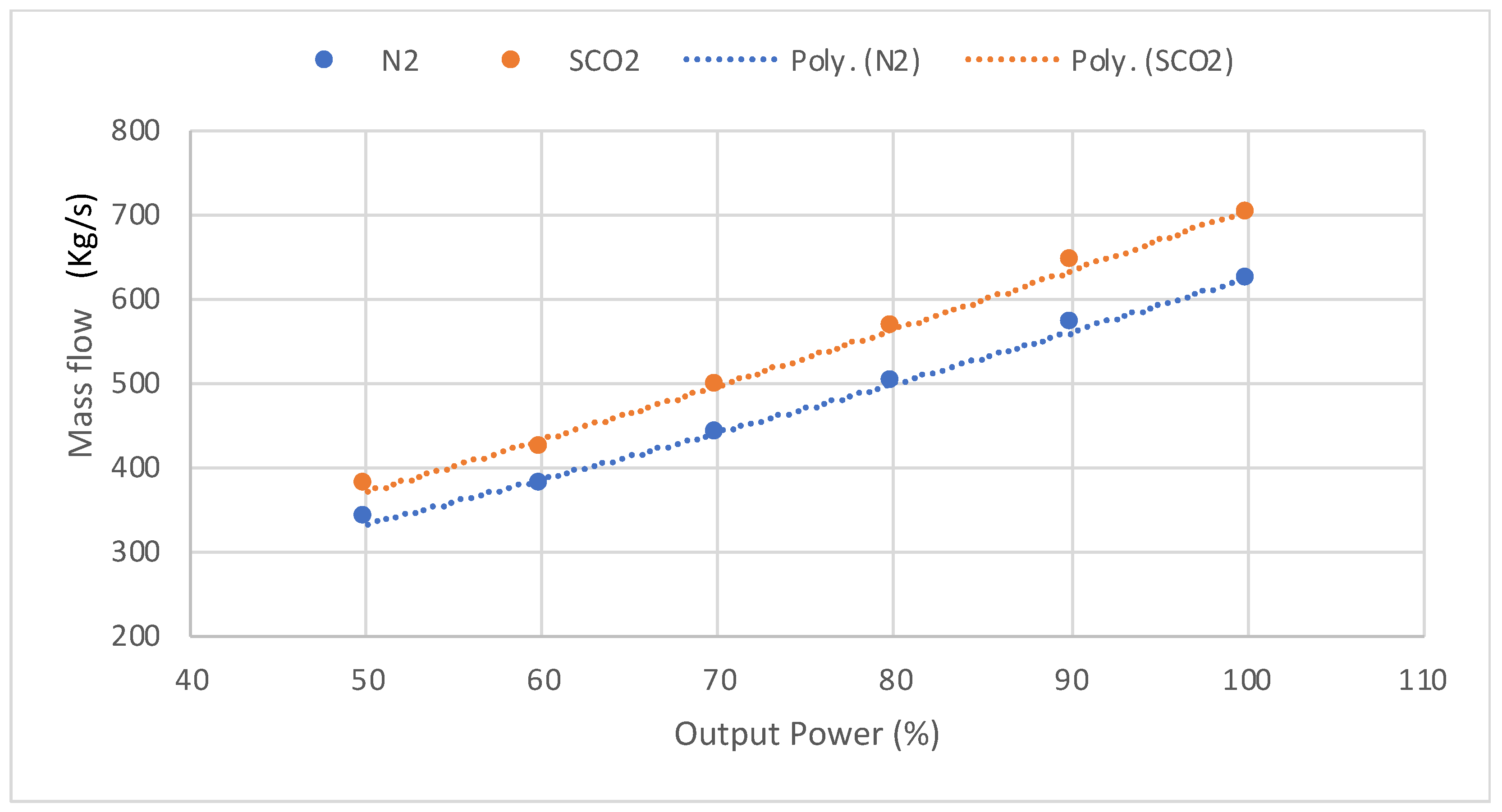
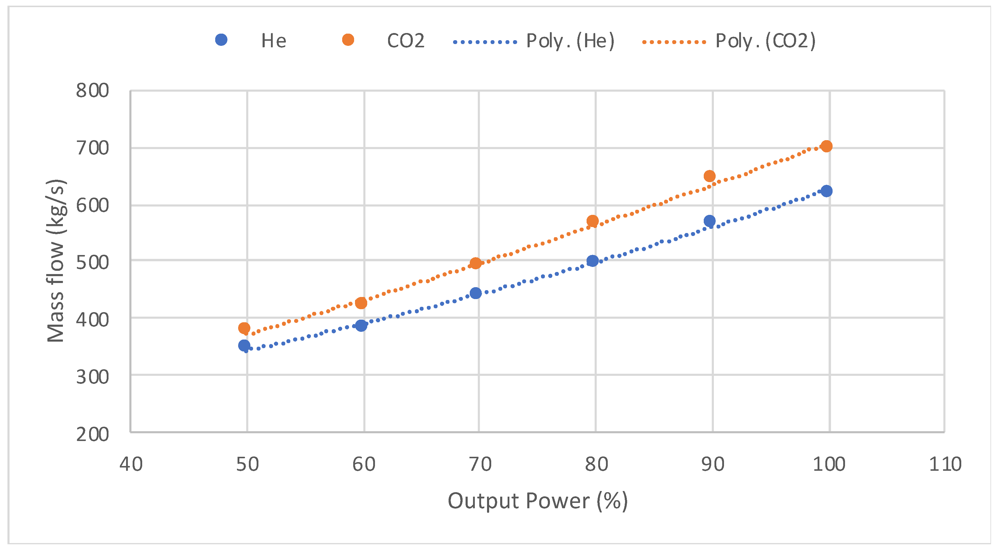
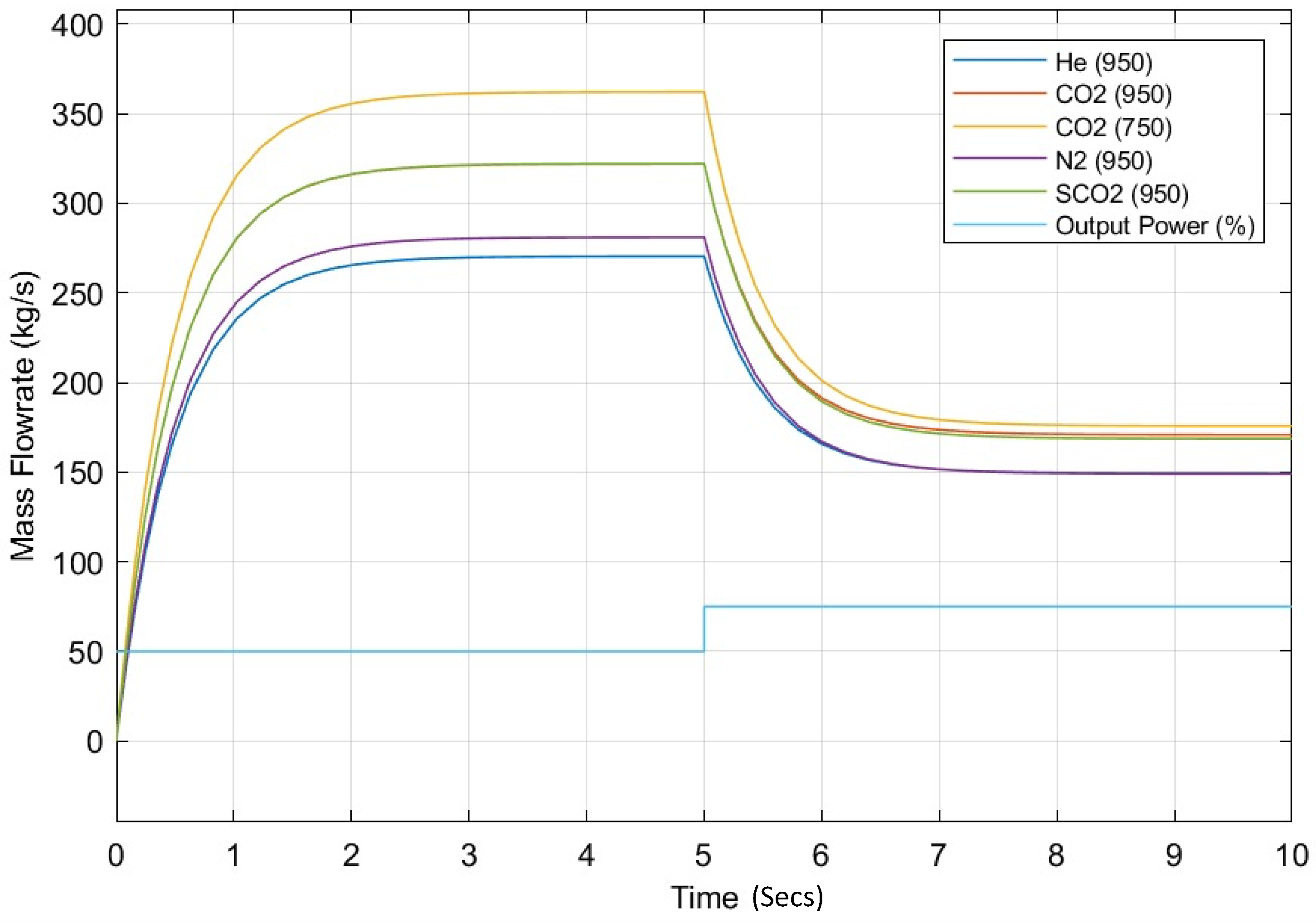
Figure 2 and
Figure 3 show the part-load profiles for the various working fluids when operating the NPP between 100% and 50% electric power. It can be noted that the trends are similar between the working fluids, with the mass-flow rate slightly higher for the carbon dioxide cycles.
The control system was designed to tune the mass-flow rate based on the percentage of the output-power demand when considering the hydrogen-offtake valve and connected pipework with a distance of about ~1 km from the thermochemical plant. Six separate control blocks were designed to deal with He, N2, low-temperature CO2, low-temperature SCO2, high-temperature CO2, and high-temperature SCO2, respectively. For all cases, the input of the designed control systems is the percentage of the power demand, and the control system will calculate the mass-flow rates as well as the pressures accordingly. The response time of the control valve is set to 0.5 s and the pressure drop in the bypass line has been set to 5% of the bypass pressure.
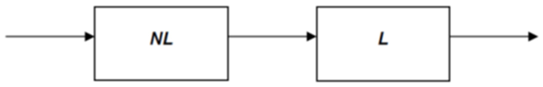
The control architecture is such that it utilises a gain-scheduling strategy to calculate the mass-flow rate based on a block-structured Wiener approach, in which a nonlinear static part will calculate the required mass-flow rate at each power demand. That block will be followed by a linear dynamic part that replicates the response time of the valve. The schematic of the control structure is shown in
Figure 4 below.
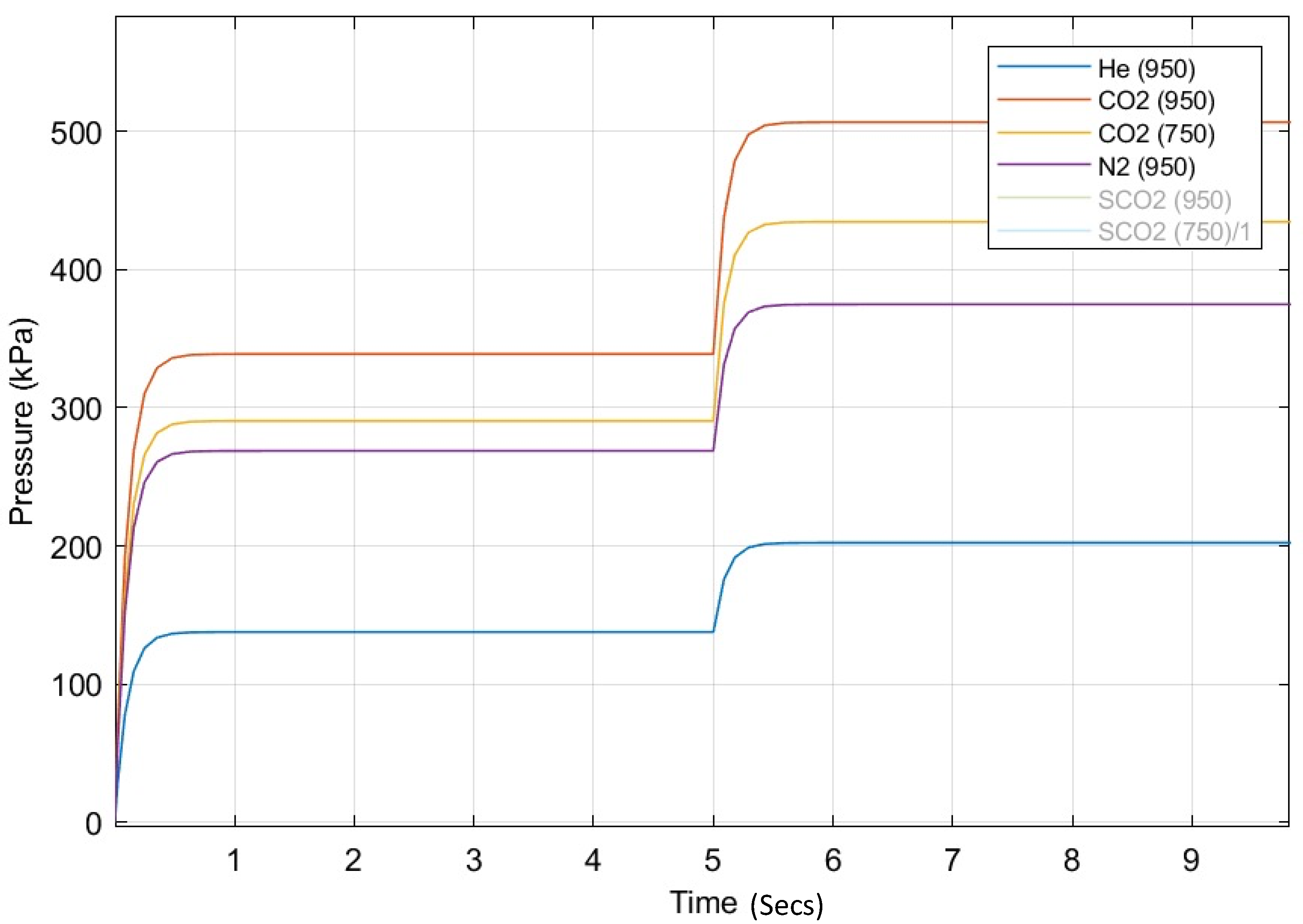
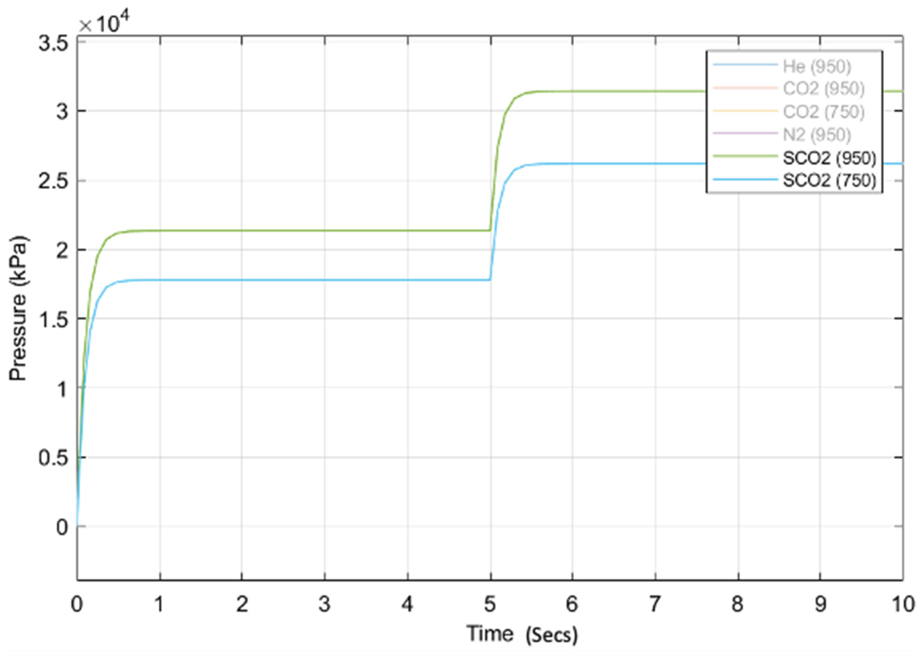
The results of the control output for a step change in the power demand from 50% to 75% are presented in
Figure 5,
Figure 6 and
Figure 7.
7. Discussion
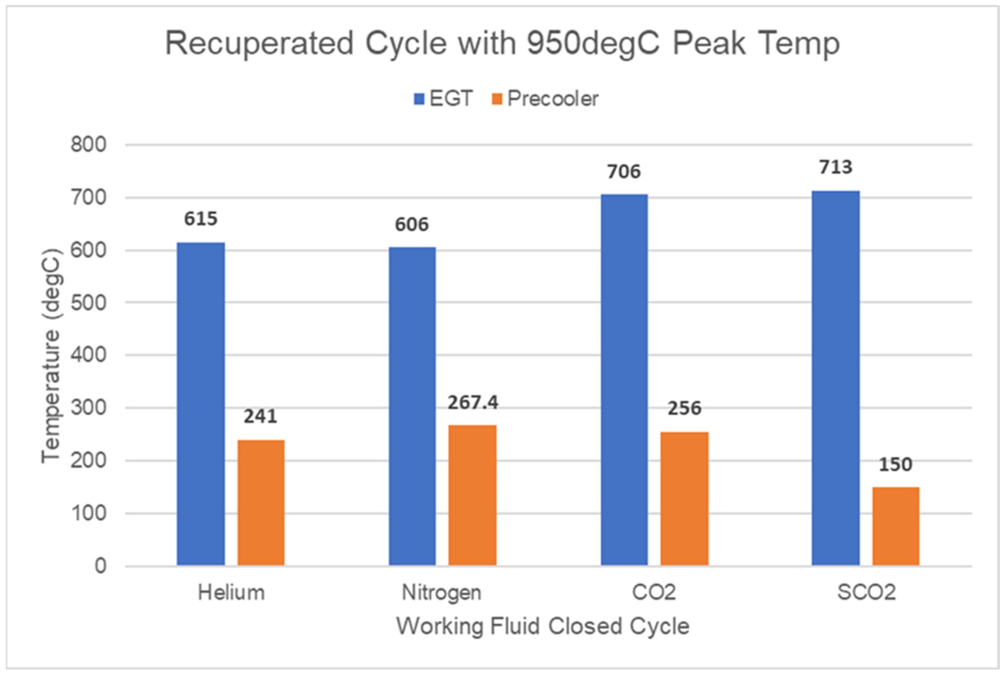
The results indicate that the flow conditions at the offtake can be maintained. The choice of working fluids affects the pressure component. As such, the SCO2 cycle would require design justification for use due to the significant system pressures. In addition to system pressures, compactness of the NPP is also critical, including pressure ratio selection. Furthermore, the recuperator allows the exhaust heat to be recaptured and used within the cycle, which further reduces the temperature prior to entering the precooler.
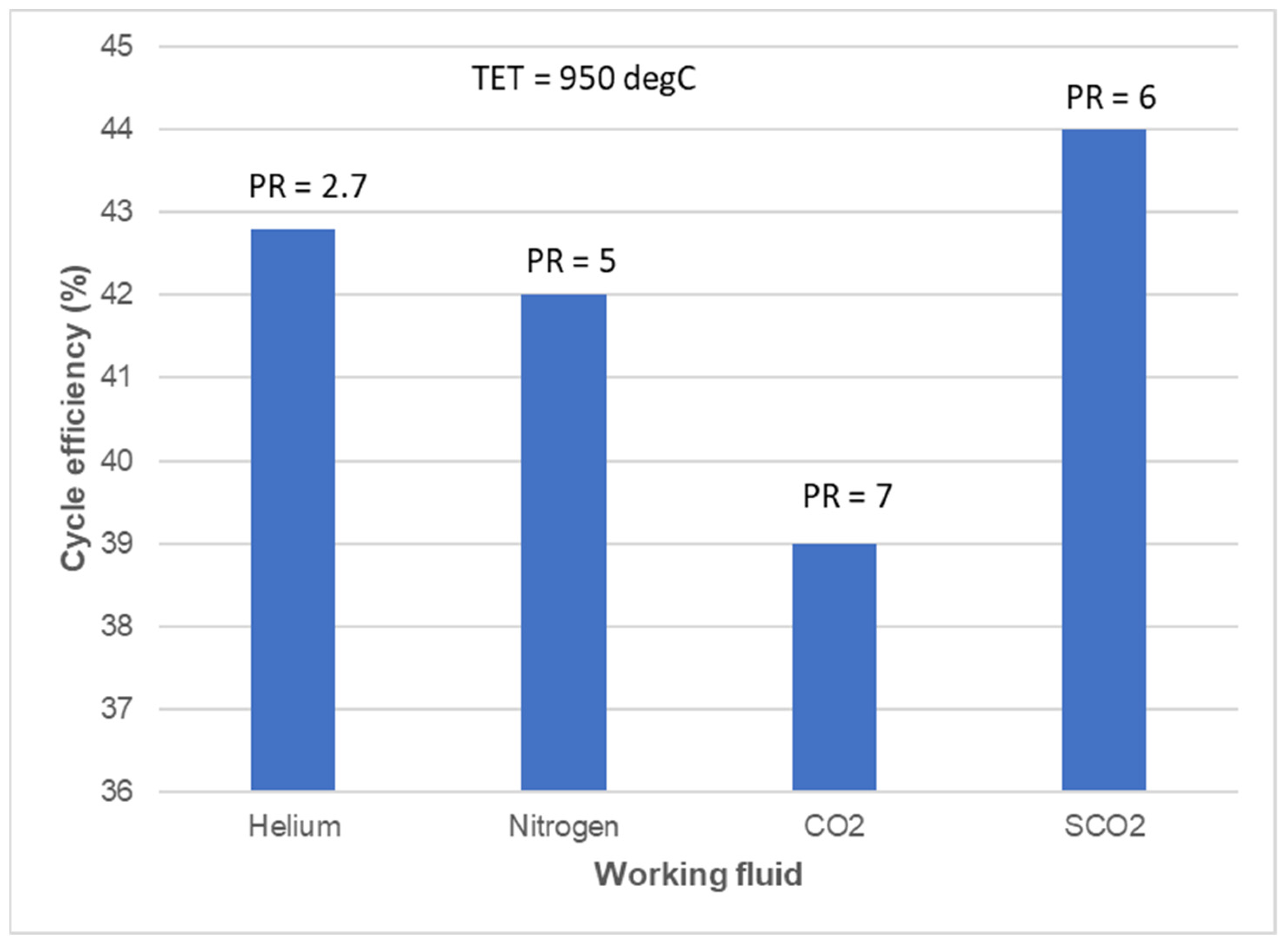
Figure 8,
Figure 9 and
Figure 10 provide some performance comparisons of the various working fluids. Helium cycle has lower system pressures and pressure ratios, which makes for a small power plant with the most turbomachinery stages. The SCO
2 plant requires a high pressure ratio, thereby leading to a compact turbomachinery, but needs to be designed for high power density. There are also efficiency benefits of 43% and 44% for helium and SCO
2 in comparison to Nitrogen and CO
2 (see
Figure 8).
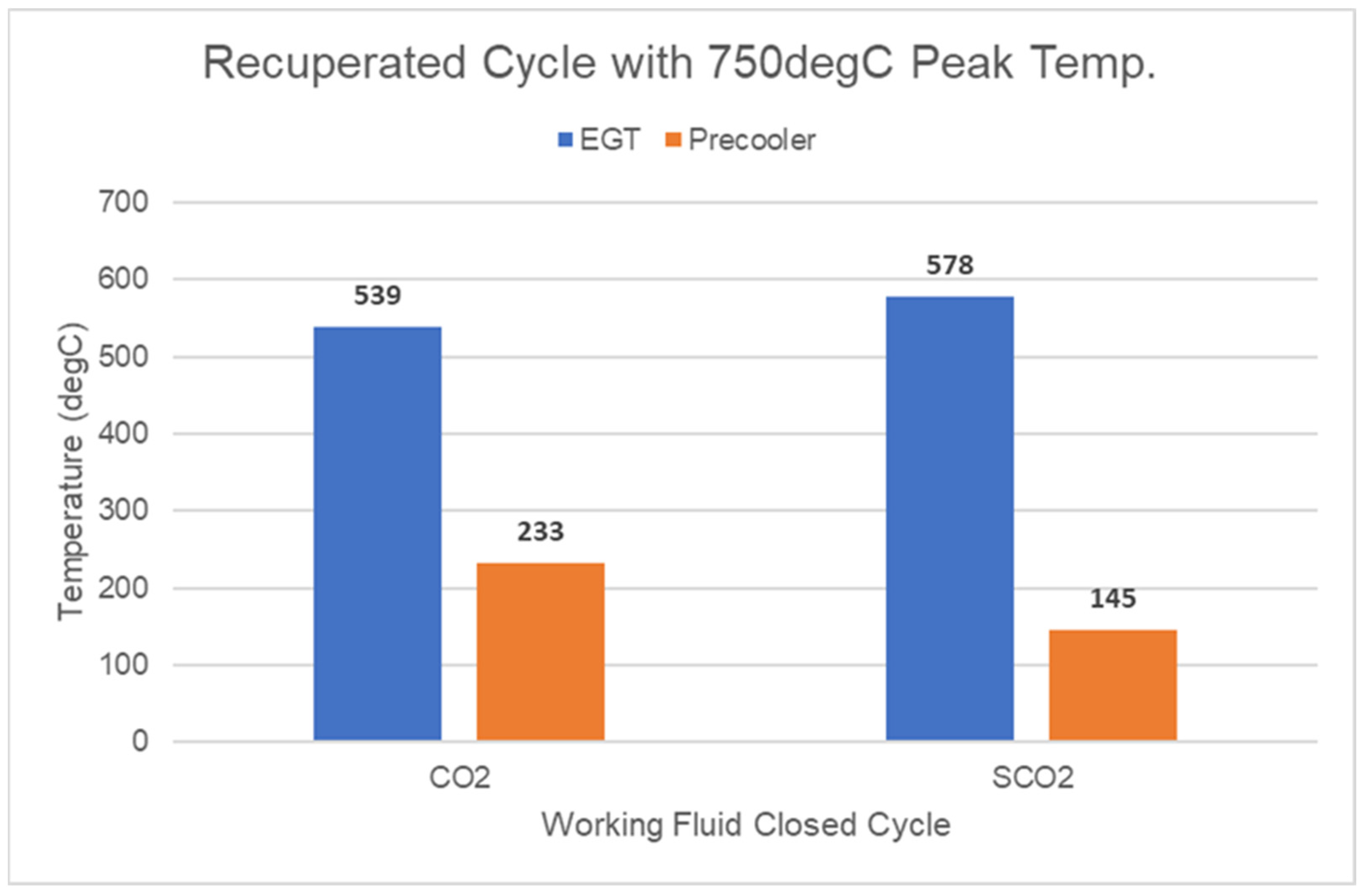
Again, when we look at the recovery of the exhaust heat (
Figure 9), the SCO
2 cycle recovers more heat, with the nitrogen cycle showing the least heat recovery for the same level of recuperator effectiveness. This is also mirrored at lower temperatures for the CO
2 and SCO
2 cycles (
Figure 10), thus justifying the excessive system pressures.
For the control system, a mix of inventory pressure control in the pipework and bypass control is proposed to enable steady power regulation during electricity and hydrogen production and complete diversion of the working fluid for hydrogen production, respectively, as the mass-flow rate is directly proportional to power with negligible effect on cycle efficiency. However, the recuperator and heat-exchanger effectiveness is considered an efficiency-limiting factor for hydrogen production and electricity generation. As such, the benefit of high-technology heat exchangers cannot be underestimated. This is also true when deciding on the thermochemical process to bolt onto the plant. The temperature of the gas at the end of the pipeline should also be considered to ensure that the minimum temperature requirement status for hydrogen production is met. The inlet temperature of the case studies is 950 °C or 750 °C. Therefore, with the assumption of a metal-plate heat exchanger with effectiveness of 0.8, the temperature at the end of the line would be above 500 °C, which is in the acceptable temperature range for some of the hydrogen-production cycles. A limiting factor for adopting a higher-temperature carbon dioxide (normal or supercritical) NPP cycle and working fluid would be materials. The cycle-material compatibility, including corrosion and oxidation of SCO2 with high-temperature materials (>750 °C), needs to be demonstrated. Helium as a working fluid also has its challenges, the main one being scarcity. Others include leakage through seals, turbomachinery tip leakages, and component welding. Nitrogen has more experience due to similarities to air, but its heat-transport properties are inferior to helium and SCO2, which would result in lower efficiencies.
Recommendations include assessing the impact on the economics of plants due to reduced availability of electricity generation, and hydrogen production and varying of the working fluid. Furthermore, although numerous verification activities have been undertaken of the toolset, validation is recommended to enable optimisation and improve applicability and accuracy.
8. Conclusions
In summary, the objective of this study was to look at the critical performance parameters associated with the nuclear power plant (NPP), the cycle working fluids, and control-system design for switching between electricity and hydrogen demand to support delivery as part of a mini grid system for a reactor delivering up to approximately 600 MWth power. The main conclusions are:
The sulphur–iodine (s–i) cycle shows better specific output in comparison to other cycles at scale, and modest efficiencies, notwithstanding the minimum temperature requirement. As such, the minimum temperature requirement forms part of the requirement that the NPP should meet when it comes to selecting a viable thermochemical method, based on the working fluid temperature from the reactor.
A small modular reactor (SMR)–high-temperature gas-cooled reactor (HTGR) configuration connected to a recuperated Brayton closed-cycle gas turbine was chosen for the study. This has flexibility to run on helium, nitrogen, carbon dioxide, and super-critical carbon dioxide. It configured cogeneration capability using an in-house tool proprietary to EGB Engineering. The plant can run at full capacity, with thermal power bypass for hydrogen production. The cogeneration option works based on grid demand.
The selected control strategy is driven by the need to control the mass flow and gas inventory, to protect the reactor’s integrity, and to ensure a bypass in the event of a sudden need to divert the all the thermal power to the hydrogen-offtake valve.
The control system was designed to tune the mass-flow rate based on the percentage of the output-power demand when considering the hydrogen-offtake valve and connected pipework with a distance of about ~1 km from the thermochemical plant. Six separate control blocks were designed to deal with He, N2, low-temperature CO2, low-temperature SCO2, high-temperature CO2, and high-temperature SCO2, respectively.
The control architecture is such that it utilises a gain-scheduling strategy to calculate the mass-flow rate based on a block-structured Wiener approach in which a nonlinear static part will calculate the required mass-flow rate at each power demand. That block will be followed by a linear dynamic part that replicates the response time of the valve.
The results indicate that the flow conditions at the offtake can be maintained. The choice of working fluids affects the pressure component. As such, the SCO2 cycle would require design justification for use due to the significant system pressures. In addition to system pressures, compactness of the NPP is also critical, including the pressure-ratio selection. Furthermore, the recuperator allows the exhaust heat to be recaptured and used within the cycle, which further reduces the temperature prior to entering the precooler.
However, the recuperator and heat-exchanger effectiveness are considered as efficiency-limiting factors for hydrogen production and electricity generation. As such, the benefit of high-technology heat exchangers cannot be underestimated. This is also true when deciding on the thermochemical process to bolt onto the plant. The temperature of the gas at the end of the pipeline should also be considered to ensure that the minimum temperature requirement status for hydrogen production is met.
Recommendations include assessing the impact on the economics of plants due to reduced availability of electricity generation, and hydrogen production and varying of working fluid.


