
Analysis of Voltage and Reactive Power Algorithms in Low Voltage Networks


Abstract
:1. Introduction
- The literature was selected following a chronological review of scientific publications, programmes, and projects related to issues of voltage control; a structured and systematic analysis is proposed.
- This article is different in that it explains the fundamental differences and similarities between voltage control techniques in detail.
- Differently than in many other studies similar to this one, this article analyzes the controllers for voltage and reactive power control.
- The voltage control strategies and methods overviewed in this article may serve as a theoretical basis and provide practical benefits for the development of PV systems in the distribution networks.
2. Voltage Control Schemes
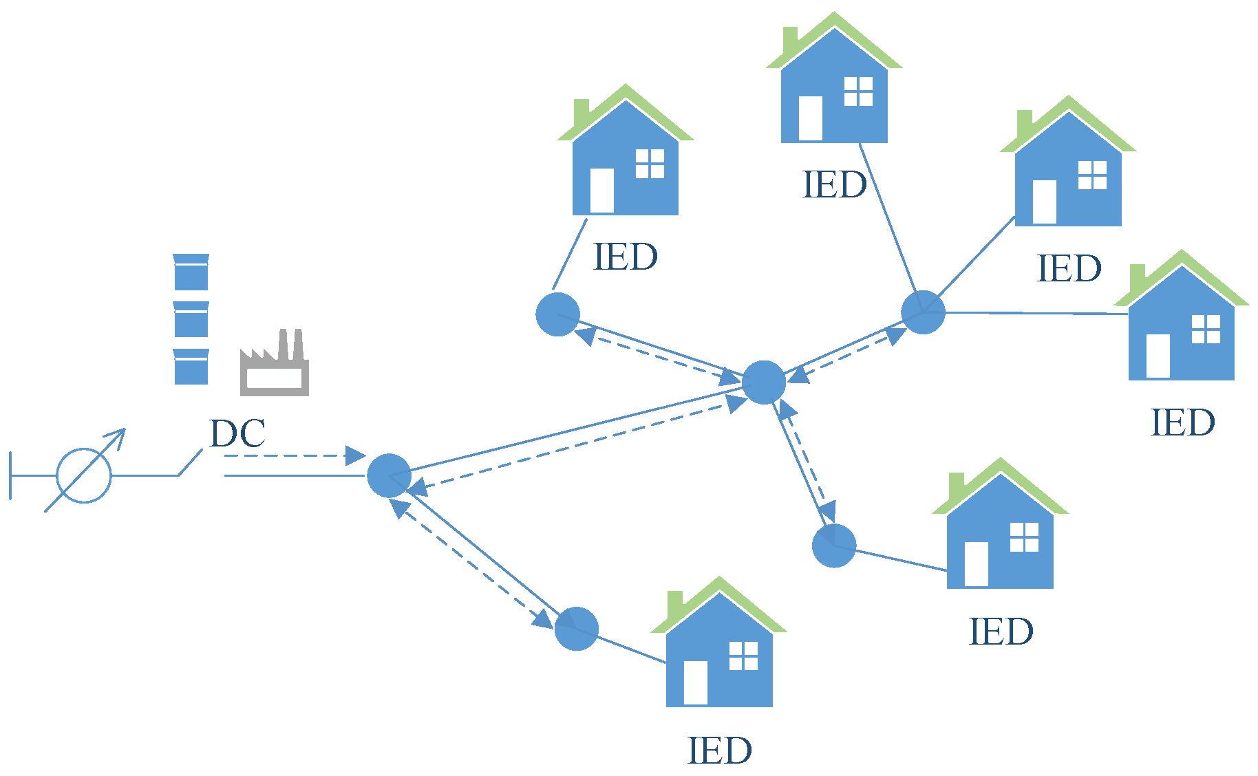
2.1. Communication-Based Schemes
2.1.1. Centralized Control
- It has no specialized control unit that could individually control the distributed generation (DG) devices [4].
- In order to adjust each subsystem, the controller of the entire system must be readjusted, and only local changes are insufficient [4].
- If a system part needs replacement, the generation must be suspended [4].
- Convergence issues are complex [3].
- In such control schemes, the calculation of control actions often depends on the problem of formulating the optimal power flow (OPF) and requires an expanded communication infrastructure and a network model [31].
- Practical adaptations of centralized control are very likely to be complicated in smart networks due to communication issues [8].
- To regulate voltage in the distribution network and keep it within the permissible range, the central coordinator needs accurate voltage information of each network node. For instance, 11 kV distribution networks take real-time measurements only at the primary substation. Thus, making sufficient real-time measurements on power lines is seldom possible. This shortage of real-time measurements needs to be compensated by calculated measurements [12].
- If the control center fails, the system cannot be operated [8].
2.1.2. Decentralized Control
- Applying decentralized control in DG allows the DN to provide additional services, such as back-ups and voltage maintenance [18].
- As systems are flexible, they can reduce network losses and increase electrical network capacity [18].
- DG can provide additional services to the DN, such as storage (backup services) and voltage maintenance [18].
- Their flexibility may have a positive effect on loss reduction and higher generation capacity [18].
- This control strategy interacts with the intermediate level of the network, which means that low voltage (LV) systems may be grouped into separate cells using intelligent, controlled substations [26].
- Decentralized methods assume that subsystem interoperability is negligible, but this assumption is not always justified and may lead to system-wide poor performance [4].
- The dynamics of the distribution system must be well interfaced, and if the control systems are designed without taking these interfaces into account, the system performance deteriorates due to the operation of local controllers, and may potentially cause the system instability [29].
2.1.3. Distributed Control
- In general, the efficiency of voltage regulation is lower than that of centralized control [8].
- The use of reactive power at the line end nodes may result in insufficient reactive power in local regions, as end-users behave stochastically, and their consumption fluctuates stochastically [8].
- If communication between the neighboring agents is not ensured and the amount of reactive power in the local region is insufficient, the subsystem cannot communicate with other neighboring agents and address its issue [8].
- If the local control center is damaged, the local regional control system will not be used [8].
- Applying distributed control to distribution systems with highly significant distributed generation (DG) requires a special communication infrastructure and may therefore be unviable, especially in the case of the existing distribution systems where such infrastructure is non-existent [29].
2.2. Local (Autonomous) Control
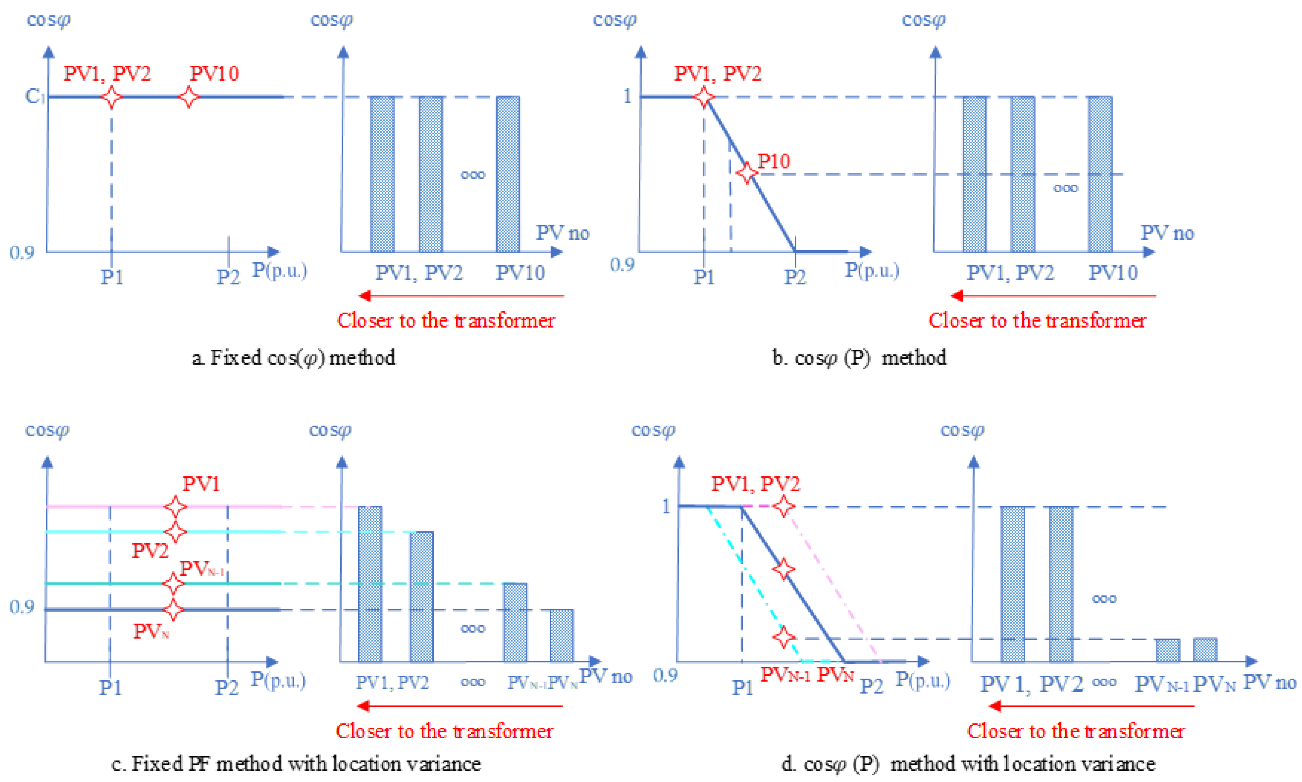
- tan ϕ = f(u): Tangent ϕ control based on the voltage of the point of common coupling (PCC). This method includes two conditions: a normal operating situation where no control action is required, and a situation where the first voltage limits are violated.
- q = f(u): Reactive power control based on the voltage of the point of common coupling (PCC). It is similar to the one mentioned above, but reactive power is directly modulated by the voltage measured on the PCC.
- tan ϕ = f(p): Tangent ϕ control is based on active power injection.
- These schemes may quickly respond to distributed generation (DG) variability and are not affected by communication failures [28].
- Local supply of reactive power reduces distribution losses and line load in distribution systems [32].
- Due to the existing condition of the low voltage network, local control is the most practical compared to other control methods or other strategies [27].
- Calculation complexity is the key obstacle in determining voltage fluctuations as the response to power fluctuations in the distribution networks [1].
2.3. Hybrid Methods
3. Controllers for Distribution Network PV Systems
3.1. Linear Controller
- Classical controllers are feedback controllers with fixed parameters.
- ⚬
- Proportional–Integral–Derivative—PID [29,46,48,49,50,51,52,53]. Adding an integrator to PD control means PID control [54]. When analyzing the variety of controllers, in terms of popularity and application in DG, approximately 90–95% are PID controllers [55]. PID-based controllers offer a promising solution to the design problem due to the relatively light and concise structure consisting of only a few parameters [29,56,57]. It gathers monitoring data from sensors, meters, and other devices [55]. The load dynamics are directly linked to the controller in this control approach, which offers balancing power for changing load parameter values [58]. This controller type is sufficient to solve most control problems, provides good performance, and its built-in parameter Ki removes steady-state error, while the derived parameter Kd improves transient response [56]. PID controllers are predominantly used as regulators in automatic voltage regulator (AVR) systems; thus, its key feature is to maintain the voltage around a reference (setpoint) and to reject load disturbances [59]. The controller is suitable for both reactive and active power control in microgrids [57].
- ⚬
- Proportional Integral—PI [41,46,50,51,61,62,63,64,65]. PI controllers have a simple structure, they are simple to design and install, but their performance is dependent on gain parameters and parametric uncertainties [41,50,63,64,65]. Various PI controllers are used to regulate the voltage of the DC coupling and to control the AC current of inverter-based PV interface systems [66]. PI controllers can take into account the interaction of the DGs and each adjust the voltage amplitude of the node to which the DG is connected by varying the active or reactive power of the DG [29]. The PI controller employed in a traditional four-switching-leg architecture performs well in steady state but not so well when there is non-linearity, parameter fluctuation, or load shift (transient condition). It necessitates a precise mathematical relationship and is thus susceptible to parameter change [67]. PI operation will deteriorate in the case of a sudden change in operating conditions, in the case where it cannot track the sine wave reference without steady-state error [41,50].
- ⚬
- ⚬
- Proportional—P [46,51]. A P controller is among the simplest to control. The input signal of a P controller is proportional to the output signal of the response. Its function is to adjust the open-loop gain of the system, to improve its steady-state accuracy, to reduce the system inertia, and to speed up the response [72]. A proportional control system is a type of linear feedback control system. The P control includes a linear correlation of the controller output (actuation signal) with the error (the difference between the measured signal and the set value). The P control is mathematically expressed by the following Equation (2)
- Proportional Resonant (PR) controller [41,46,50,68,77]. The PR controllers are designed to control AC voltage and/or AC current [68]. The basic concept behind the PR controller is to convert the high gain characteristic of the PI controller in DC signals to AC signals [68]. To compare a PI controller with a PR controller, the PR controller allows evaluation of the dynamic system behavior in the case of external disturbances [78]. The main function of the PR controller is to ensure unlimited gain at the selected resonant frequency, so that the steady-state error at this frequency is reduced to zero [79].
- Linear–Quadratic–Gaussian (LQG) controller [46,53,80]. This is a Kalman filter-based linear–quadratic regulator [57]. The LQG controller optimizes the (steady-state) cost function, which is quadratic in the state and the control input, given a linear dynamical system with known statistics of the noise entering the dynamics, as well as the measurements [57,81]. The standard optimal problem of LQG control is to choose such an input to a linear system that maximizes the expectation of a quadratic function that depends on the output and control of realized state trajectories [79]. The optimal target value depends on the quality of the state monitoring [82]. By reducing the cost function, this controller anticipates future steps and decreases projected error [57].
3.2. Non-Linear Controller
- Sliding mode controller (SMC) [41,46,53,83,84,85]. The sliding mode controller (SMC) is among the most well-known non-linear control methods, which is known to be an excellent controller to overcome uncertainty problems [85,86,87]. The SMC works by driving the non-linear phase trajectory onto a specific area in the state space termed the sliding or switching surface and keeping it there for all time [47]. In addition, compared to other non-linear controller design approaches, SMC implementation is quite simple [69]. There are several high-order sliding mode controllers available, which are more robust than one-order SMCs [53]. SMCs offer many advantages over a linear PI or PID controller, providing stability even in the case of high line and load fluctuations, as well as robustness, good dynamic response, and simple implementation [46,47]. The primary disadvantage of traditional SMC is the possibility of chattering, which is defined as switching around the manifold [86,88]. However, due to its complexity and the significant degree of vibration associated with it, the sliding mode control arrangement is also impractical [53].
- Partial Feedback Linearization controller (PFLC) [46,89]. Feedback linearization is a method of non-linear control design that algebraically converts the dynamics of a non-linear system into a completely or partially linear one, allowing linear control techniques to be used [90]. Exact feedback linearization converts a non-linear system into a fully linear one, whereas partial feedback linearization transforms the system into a partially linearized one [46,89]. Control design is thus based on well-known linear control techniques that cancel out undesirable non-linear components [87].
- Hysteresis controller (HC) [46,91]. In comparison to other controllers suggested in the literature, hysteresis current controllers are recognized for their resilience, quick error tracking, superior dynamic responsiveness, and ease of implementation [92,93]. A traditional HC employs a separate controller with a predetermined hysteresis band for each phase of the load to determine the switching state of the associated inverter leg in order to maintain current error within the hysteresis band [92]. The benefits of utilizing a hysteresis control are primarily its simplicity, resilience, independence from load factors, and good transient response [94]. However, it has several significant disadvantages, such as limit cycle oscillations, overshoot in current errors, sub-harmonic components in the current, and sub-optimal switching vector selection [70,92,95]. HC has high switching losses and acoustic noise [96]. The hysteresis controller has two major drawbacks: it does not have a set switching frequency, resulting in a broad frequency spectrum, and current ripple is relatively significant, potentially reaching double band limit for the phase current hysteresis controller [94].
3.3. Robust Controller
- H-Infinity (H∞) controller (HIC) [46,94]. HIC is a repeated control approach for improving the performance of droop controllers, voltage, and current control loops. It has the ability to solve multi-objective and multivariate problems [97,98]. The goals of HIC synthesis include assuring system stability in the face of uncertainty, often known as robust stability [99]. In general, the HIC optimization technique solves robust stabilization and nominal performance designs for linear, time-invariant control systems [95]. To use this approach, the control problem must first be transformed into a mathematical optimization problem [98]. The choice of weighting functions in this controller design may be included into the design goals of tracking performance and desired robustness to create desired loop shapes (ideal profiles of the closed-loop transfer functions). With suitable weighting function adjustment, the synthesized HIC controller may display strong gains near the line frequency and attenuate high-frequency signals [100]. In the presence of system disturbances and uncertainties, the HIC controller is capable of maintaining robust multivariable linear systems’ stability [101]. This technique has the benefit of allowing the designer to handle the most generic type of control architecture, allowing for explicit accounting of uncertainties, disturbances, and performance metrics [98]. In both grid-connected and isolated modes, the technique may be used for a variety of applications in power management and the control of DGs [98]. However, one problem of the HIC controller is the difficulty in analog circuit implementation owing to its high order and the necessity of sophisticated manipulation of the system transfer function [100]. Non-linear restrictions are also poorly dealt with [46].
- Mu (μ)-Synthesis controller (MSC) [46,102]. Controller design in Mu-synthesis is based on the concept of structured single value [102,103]. MSC may be used to assess the impact of both structured and unstructured uncertainty on system performance [102]. Uncertainty is divided into two types: parametric uncertainties and unmodeled dynamics [103]. The μ-synthesis approach not only reduces the maximum error energy for all command and disturbance inputs, but it also stabilizes the closed-loop system for structured plant uncertainties with restricted H∞ norm. It is a good feature to consider, especially when developing controllers for plants with unmodeled high-frequency dynamics, when plants experience defective operating circumstances, or when plant parameters change due to aging, e.g., of a power system [104]. MSC may also be used to design control systems that are insensitive to classes of predicted differences between a model and the physical process that has to be controlled [105].
3.4. Adaptive Controller
3.5. Predictive Controller
- DeadBeat controller (DBC) [46,111]. In the evolution of digital systems, deadbeat controllers have become one of the key choices [112]. The deadbeat controller has been demonstrated to be an optimal and resilient controller [113]. Deadbeat control is widely employed in inverters with L filters due to its ease of installation and large control bandwidth [114]. The DB control can reduce the control error to zero in a short period of time, resulting in a quick transient reaction [115]. Due to its fast response, zero steady-state error, digital nature, easy and direct implementation on digital processors, simple algorithm, constant switching frequency, and fast dynamic response, the deadbeat predictive method is among the most widely used approaches for controlling power converters [116]. In general, the goal of a control system is to attain the intended value with zero steady-state error in less than 2 s [113]. In comparison to other predictive control techniques such as the Finite Control Set Model Predictive Controller (FCS-MPC), DBC offers high dynamic performance while maintaining a constant switching frequency [115]. Model and parameter mismatches are frequent causes of controller sensitivity [111].
- Model Predictive Controller (MPC) [46,117]. MPC is an optimum controller built on the basis of a cost function that aids in predicting future states. The MPC controller delivers stable control action with a wide gain and phase margin [57]. The MPC only takes into account system limitations and non-linearities during the design stage of the controller [46]. MPC has the advantage of not allowing the present timeslot to be optimized while considering future timeslots. The model predictive controller’s applicability is restricted by its sluggish reaction time and low bandwidth [60].
3.6. Intelligent Controller
- Neural network controller (NNC) [46,118]. In the systems, neural networks can be utilized as a controller [119]. Self-adaptive characteristics enable NNC to control non-linearities, uncertainties, and parameter changes with remarkable precision [118]. NNC may utilize a neural network in a control system to govern complicated non-linear objects that are difficult to accurately represent mathematically [120]. In order to apply an NNC, four key stages must be completed: data collection; input selection; choosing an NNC architecture; NNC training and testing [121]. The challenges in these approaches are that a significant amount of processing time is necessary for the database in order to train the NNC using the supervised learning algorithm [122]. When the system is in a new control state with an uncertain circumstance, this technique can make an appropriate choice [119]. Due to its self-learning capabilities, parallel design allows the controller to compute quicker, and it does not require perfect input and output relationships, allowing it to manage non-linearity. As a result, it is more durable than a traditional controller [67].
- Repetitive controller (RC) [46,62]. Due to its better error cancelation properties, a repetitive control (RC)-based controller is adept in tracking or eliminating any periodic signal, including any order harmonics [62]. Repetitive controllers, on the other hand, meet the internal model principle (IMP) in a positive feedback loop by using a delay element that corresponds to the fundamental period. A low-pass first-order filter is linked in series with the delay element to provide steady operation while avoiding noise amplification. The reduction in size and displacement of resonance peaks in the controller frequency response causes a loss of tracking ability while following the reference signal, which is one drawback of this method [123].
- Fuzzy Logic Controller (FLC) [46,49,51,52,65,124]. Fuzzy logic has received a lot of attention in structure control due to its simplicity and robustness (reliability) [54]. FLC depends on a set of defined rules that is translated into a fuzzy logic language [125]. Fuzzy control, in essence, is an adaptive and non-linear control that provides stable performance for a linear or non-linear plant with variable parameters. Compared to conventional controllers, FLCs are generally not effective if the structure of the controlled system is uncertain, as simple FLCs (type 1 FLCs) have limited capability to directly handle data uncertainties [52]. The FLC controller has an advantage over the PI controller as it better controls the active power fed to the grid, and better monitors the grid current and maximum power point tracking for the PV array [51,64,65]. Researchers often consider the FLC controller as a black-box function generator that can generate the desired f (function value) or an approximation of it [126]. The main advantage of FLC is that it can be applied to systems that are non-linear, the mathematical models of which are difficult to obtain. Another advantage is that the controller can be designed to apply heuristic rules that reflect human expert experience [52]. The most difficult aspect of employing fuzzy control approaches is determining the proper membership functions and control rules quickly and effectively [58].
4. Discussion
5. Conclusions
Author Contributions
Funding
Institutional Review Board Statement
Informed Consent Statement
Data Availability Statement
Conflicts of Interest
References
- Efkarpidis, N.; de Rybel, T.; Driesen, J. Technical assessment of centralized and localized voltage control strategies in low voltage networks. Sustain. Energy Grids Netw. 2016, 8, 85–97. [Google Scholar] [CrossRef]
- Xu, Z.; Wang, X.; Yang, J.; Zhang, F. A review on voltage control for distribution systems with large-scale distributed photovoltaic power integration. IOP Conf. Series: Earth Environ. Sci. 2019, 371, 052027. [Google Scholar] [CrossRef]
- Azzouz, M.A.; Farag, H.E.; El-Saadany, E.F. Real-Time Fuzzy Voltage Regulation for Distribution Networks Incorporating High Penetration of Renewable Sources. IEEE Syst. J. 2014, 11, 1702–1711. [Google Scholar] [CrossRef]
- Yazdanian, M.; Mehrizi-Sani, A. Distributed Control Techniques in Microgrids. IEEE Trans. Smart Grid 2014, 5, 2901–2909. [Google Scholar] [CrossRef]
- Aleem, S.A.; Hussain, S.M.S.; Ustun, T.S. A Review of Strategies to Increase PV Penetration Level in Smart Grids. Energies 2020, 13, 636. [Google Scholar] [CrossRef] [Green Version]
- Schiffer, J.; Seel, T.; Raisch, J.; Sezi, T. Voltage Stability and Reactive Power Sharing in Inverter-Based Microgrids With Consensus-Based Distributed Voltage Control. IEEE Trans. Control Syst. Technol. 2015, 24, 96–109. [Google Scholar] [CrossRef] [Green Version]
- Darwish, E.M.; Hasanien, H.M.; Atallah, A.; El-Debeiky, S. Reactive power control of three-phase low voltage system based on voltage to increase PV penetration levels. Ain Shams Eng. J. 2018, 9, 1831–1837. [Google Scholar] [CrossRef]
- Abessi, A.; Vahidinasab, V.; Ghazizadeh, M.S. Centralized Support Distributed Voltage Control by Using End-Users as Reactive Power Support. IEEE Trans. Smart Grid 2015, 7, 178–188. [Google Scholar] [CrossRef]
- Petinrin, J.O.; Shaaband, M. Impact of renewable generation on voltage control in distribution systems. Renew. Sustain. Energy Rev. 2016, 65, 770–783. [Google Scholar] [CrossRef]
- Ma, W.; Wang, W.; Chen, Z.; Wu, X.; Hu, R.; Tang, F.; Zhang, W. Voltage regulation methods for active distribution networks considering the reactive power optimization of substations. Appl. Energy 2021, 284, 116347. [Google Scholar] [CrossRef]
- Xie, Y.; Liu, L.; Wu, Q.; Zhou, Q. Robust model predictive control based voltage regulation method for a distribution system with renewable energy sources and energy storage systems. Int. J. Electr. Power Energy Syst. 2020, 118, 105749. [Google Scholar] [CrossRef]
- Mahmud, N.; Zahedi, A. Review of control strategies for voltage regulation of the smart distribution network with high penetration of renewable distributed generation. Renew. Sustain. Energy Rev. 2016, 64, 582–595. [Google Scholar] [CrossRef]
- Hubana, T.; Begić, E.; Saric, M. Voltage Control in Distribution Network Using Variable Power Factor Operated Distributed Generation. In Proceedings of the IEEE SYPC, Sarajevo, Bosnia and Herzegovina, 1–4 December 2016. [Google Scholar]
- Howlader, A.M.; Sadoyama, S.; Roose, L.R.; Sepasi, S. Distributed voltage regulation using Volt-Var controls of a smart PV inverter in a smart grid: An experimental study. Renew. Energy 2018, 127, 145–157. [Google Scholar] [CrossRef]
- Liu, B.; Tong, X.; Zhong, M.; Zhang, X.; Deng, J. Local Voltage Control Strategy Based on Remaining Capacity of PV Grid-connected Inverter. In Proceedings of the 2018 IEEE International Power Electronics and Application Conference and Exposition (PEAC), Shenzhen, China, 4–7 November 2018; pp. 1–5. [Google Scholar]
- Tanaka, K. Decentralized voltage control in distribution systems by distributed generators. In Proceedings of the 2009 IEEE International Symposium on Industrial Electronics, Seoul, Korea, 5–8 July 2009; pp. 554–559. [Google Scholar] [CrossRef]
- Abbott, S.R.; Fox, B.; Morrow, D.J. Sensitivity-based dispatch of DG for voltage control. In Proceedings of the 2014 IEEE PES General Meeting|Conference & Exposition, National Harbor, MD, USA, 27–31 July 2014; pp. 1–5. [Google Scholar]
- Calderaro, V.; Conio, G.; Galdi, V.; Massa, G.; Piccolo, A. Optimal Decentralized Voltage Control for Distribution Systems with Inverter-Based Distributed Generators. IEEE Trans. Power Syst. 2013, 29, 230–241. [Google Scholar] [CrossRef]
- Zhu, H.; Liu, H.J. Fast Local Voltage Control Under Limited Reactive Power: Optimality and Stability Analysis. IEEE Trans. Power Syst. 2015, 31, 3794–3803. [Google Scholar] [CrossRef]
- Hamrouni, N.; Younsi, S.; Jraidi, M. A Flexible Active and Reactive Power Control Strategy of a LV Grid Connected PV System. Energy Procedia 2019, 162, 325–338. [Google Scholar] [CrossRef]
- Mirbagheri, S.M.; Merlo, M. Optimal reactive power flow procedure to set up an effective local voltage control. Sustain. Energy Technol. Assess. 2020, 39, 100709. [Google Scholar] [CrossRef]
- Ghosh, S.; Rahman, S.; Pipattanasomporn, M. Distribution Voltage Regulation Through Active Power Curtailment With PV Inverters and Solar Generation Forecasts. IEEE Trans. Sustain. Energy 2016, 8, 13–22. [Google Scholar] [CrossRef]
- Ahmadi, M.; Adewuyi, O.B.; Danish, M.S.S.; Mandal, P.; Yona, A.; Senjyu, T. Optimum coordination of centralized and distributed renewable power generation incorporating battery storage system into the electric distribution network. Int. J. Electr. Power Energy Syst. 2020, 125, 106458. [Google Scholar] [CrossRef]
- Ilyushin, P.; Berezovskiy, P.; Filippov, S. Approaches to establishing voltage control requirements for distributed generation units. E3S Web Conf. 2019, 139, 01006. [Google Scholar] [CrossRef]
- Malekpour, A.R.; Pahwa, A. Reactive power and voltage control in distribution systems with photovoltaic generation. In Proceedings of the 2012 North American Power Symposium (NAPS), Champaign, IL, USA, 9–11 September 2012; pp. 1–6. [Google Scholar] [CrossRef]
- Bernal, A.E.; López, M.B.; Molinas, M. Decentralized Fuzzy-Based Voltage Control for LV Distribution Systems. In Proceedings of the 33rd European Photovoltaic Solar Energy Conference and Exhibition, Amsterdam, The Netherlands, 25–29 September 2017; Volume 1, pp. 2171–2175. [Google Scholar]
- Yin, F.; Zhao, P.; Wang, Y.; Li, Z.; Wang, Y.; Xiao, X. Coordinated central and local voltage control in low voltage distribution network with photovoltaic generation. In Proceedings of the 2019 IEEE 3rd International Electrical and Energy Conference (CIEEC), Beijing, China, 7–9 September 2019; pp. 298–302. [Google Scholar] [CrossRef]
- Antoniadou-Plytaria, K.E.; Kouveliotis-Lysikatos, I.N.; Georgilakis, P.S.; Hatziargyriou, N.D. Distributed and Decentralized Voltage Control of Smart Distribution Networks: Models, Methods, and Future Research. IEEE Trans. Smart Grid 2017, 8, 2999–3008. [Google Scholar] [CrossRef]
- Russou, M.; Fusco, G. Robust decentralized PI controllers design for voltage regulation in distribution networks with DG. Electr. Power Syst. Res. 2019, 172, 129–139. [Google Scholar] [CrossRef]
- Almasalma, H.; Claeys, S.; Mikhaylov, K.; Haapola, J.; Pouttu, A.; Deconinck, G. Experimental Validation of Peer-to-Peer Distributed Voltage Control System. Energies 2018, 11, 1304. [Google Scholar] [CrossRef] [Green Version]
- Olivier, F.; Aristidou, P.; Ernst, D.; Van Cutsem, T. Active Management of Low-Voltage Networks for Mitigating Overvoltages Due to Photovoltaic Units. IEEE Trans. Smart Grid 2015, 7, 926–936. [Google Scholar] [CrossRef] [Green Version]
- Gandhi, O.; Zhang, W.; Rodríguez-Gallegos, C.D.; Verbois, H.; Sun, H.; Reindl, T.; Srinivasan, D. Local reactive power dispatch optimisation minimising global objectives. Appl. Energy 2020, 262, 114529. [Google Scholar] [CrossRef]
- Cavraro, G.; Carli, R. Local and Distributed Voltage Control Algorithms in Distribution Networks. IEEE Trans. Power Syst. 2017, 33, 1420–1430. [Google Scholar] [CrossRef]
- Cheng, Z.; Li, Z.; Liang, J.; Si, J.; Dong, L.; Gao, J. Distributed coordination control strategy for multiple residential solar PV systems in distribution networks. Int. J. Electr. Power Energy Syst. 2019, 117, 105660. [Google Scholar] [CrossRef]
- Guo, Y.; Wu, Q.; Gao, H.; Shen, F. Distributed voltage regulation of smart distribution networks: Consensus-based information synchronization and distributed model predictive control scheme. Int. J. Electr. Power Energy Syst. 2019, 111, 58–65. [Google Scholar] [CrossRef]
- Vargas, L.R.; Eichkoff, H.S.; da Silva, G.S.; de Mello, A.P.C. Local volt/var Control Strategy for Smart Grids using Photovoltaic Smart Inverters. In Proceedings of the 2019 IEEE PES Innovative Smart Grid Technologies Conference—Latin America (ISGT Latin America), Gramado, Brazil, 15–18 September 2019; pp. 1–6. [Google Scholar]
- Arshad, A.; Lehtonen, M. A comprehensive voltage control strategy with voltage flicker compensation for highly PV penetrated distribution networks. Electr. Power Syst. Res. 2019, 172, 105–113. [Google Scholar] [CrossRef]
- Khan, S.; Zehetbauer, P.; Schwalbe, R. Evaluation of sensitivity based coordinated volt-var control and local reactive power for voltage regulation and power exchange across system boundaries in smart distribution networks. Electr. Power Syst. Res. 2020, 192, 106975. [Google Scholar] [CrossRef]
- Schultis, D.-L.; Ilo, A.; Schirmer, C. Overall performance evaluation of reactive power control strategies in low voltage grids with high prosumer share. Electr. Power Syst. Res. 2019, 168, 336–349. [Google Scholar] [CrossRef]
- Merlo, M.; Monfredini, G. Voltage Control on LV Distribution Network: Local Regulation Strategies for DG Exploitation. Res. J. Appl. Sci. Eng. Technol. 2014, 7, 4891–4905. [Google Scholar] [CrossRef]
- Suresh, V.; Pachauri, N.; Vigneysh, T. Decentralized control strategy for fuel cell/PV/BESS based microgrid using modified fractional order PI controller. Int. J. Hydrogen Energy 2020, 46, 4417–4436. [Google Scholar] [CrossRef]
- El Assri, N.; Chabaa, S.; Lmesri, K.; Jallal, M.A.; Zeroual, A. Modeling techniques for decentralized energy systems applied in smart grids. E3S Web Conf. 2021, 297, 01068. [Google Scholar] [CrossRef]
- Elmouatamid, A.; Ouladsine, R.; Bakhouya, M.; El Kamoun, N.; Khaidar, M.; Zine-Dine, K. Review of Control and Energy Management Approaches in Micro-Grid Systems. Energies 2020, 14, 168. [Google Scholar] [CrossRef]
- Battula, A.R.; Vuddanti, S.; Salkuti, S.R. Review of Energy Management System Approaches in Microgrids. Energies 2021, 14, 5459. [Google Scholar] [CrossRef]
- Kler, D.; Rana, K.; Kumar, V. A nonlinear PID controller based novel maximum power point tracker for PV systems. J. Frankl. Inst. 2018, 355, 7827–7864. [Google Scholar] [CrossRef]
- Zeb, K.; Uddin, W.; Khan, M.A.; Ali, Z.; Ali, M.U.; Christofides, N.; Kim, H.J. A comprehensive review on inverter topologies and control strategies for grid connected photovoltaic system. Renew. Sustain. Energy Rev. 2018, 94, 1120–1141. [Google Scholar] [CrossRef]
- Kumar, K.R. Implementation of sliding mode controller plus proportional double integral controller for negative output elementary boost converter. Alex. Eng. J. 2016, 55, 1429–1445. [Google Scholar] [CrossRef] [Green Version]
- Sinan, S.; Elnady, A. Optimized PID controller based voltage oriented control of the 7-level diode clamped inverter for distributed generation system. In Proceedings of the 2017 International Conference on Electrical and Computing Technologies and Applications (ICECTA), Ras Al Khaimah, United Arab Emirates, 21–23 November 2017; pp. 1–5. [Google Scholar] [CrossRef]
- Parise, G.; Martirano, L.; Kermani, M.; Kermani, M. Designing a power control strategy in a microgrid using PID/fuzzy controller based on battery energy storage. In Proceedings of the 2017 IEEE International Conference on Environment and Electrical Engineering and 2017 IEEE Industrial and Commercial Power Systems Europe (EEEIC/I&CPS Europe), Milan, Italy, 6–9 June 2017; pp. 1–5. [Google Scholar]
- Amini, B.; Roshanfekr, R.; Hajipoor, A.; Mousavi, S.Y.M. Interface converter control of distributed generation in microgrids using fractional proportional—Resonant controller. Electr. Power Syst. Res. 2021, 194, 107097. [Google Scholar] [CrossRef]
- Bakhoda, O.Z.; Menhaj, M.B.; Gharehpetian, G.B. MPPT for a three-phase grid-connected PV system (Fuzzy Logic Controller vs. PI Controller). In Proceedings of the 2015 4th Iranian Joint Congress on Fuzzy and Intelligent Systems (CFIS), Zahedan, Iran, 9–11 September 2015; pp. 1–5. [Google Scholar]
- El-Nagar, A.M.; El-Bardini, M.; El-Rabaie, N.M. Intelligent control for nonlinear inverted pendulum based on interval type-2 fuzzy PD controller. Alex. Eng. J. 2014, 53, 23–32. [Google Scholar] [CrossRef]
- Li, J.; Yu, T. A new adaptive controller based on distributed deep reinforcement learning for PEMFC air supply system. Energy Rep. 2021, 7, 1267–1279. [Google Scholar] [CrossRef]
- Satyam, P.; Yu, W.; Li, X. Bidirectional active control of structures with type-2 fuzzy PD and PID. Int. J. Syst. Sci. 2018, 49, 766–782. [Google Scholar]
- Arunraja, A.; Jayanthy, S. Tuning methods of various controllers. Mater. Today Proc. 2021. [Google Scholar] [CrossRef]
- Mammadov, A.D.; Dincel, E.; Söylemez, M.T. Analytical design of discrete PI–PR controllers via dominant pole assignment. ISA Trans. 2021, in press. [Google Scholar] [CrossRef]
- Rahman, M.A.; Sarkar, S.K.; Badal, F.R.; Das, S.K. Optimal Design of Integral Linear Quadratic Gaussian Controller for Controlling of Islanded Microgrid Voltage. In Proceedings of the 2018 International Conference on Advancement in Electrical and Electronic Engineering (ICAEEE), Gazipur, Bangladesh, 22–24 November 2018; pp. 1–4. [Google Scholar]
- Rahman, M.; Sarker, S.; Sarkar, S.K.; Das, S.K. PHEV Participating in Load Frequency Regulation of Interconnected Smart Grid Using Integral Linear Quadratic Gaussian Control Approach. In Proceedings of the 2019 International Conference on Energy and Power Engineering (ICEPE), Dhaka, Bangladesh, 14–16 March 2019; pp. 1–6. [Google Scholar] [CrossRef]
- Veinović, S.; Stojić, D.; Joksimović, D. Optimized four-parameter PID controller for AVR systems with respect to robustness. Int. J. Electr. Power Energy Syst. 2021, 135, 107529. [Google Scholar] [CrossRef]
- Siddique, A.B.; Munsi, S.; Sarker, S.K.; Das, S.K.; Islam, R. Voltage and current control augmentation of islanded microgrid using multifunction model reference modified adaptive PID controller. Int. J. Electr. Power Energy Syst. 2019, 113, 492–501. [Google Scholar] [CrossRef]
- Zolfaghari, M.; Arani, A.A.K.; Gharehpetian, G.B.; Abedi, M. A fractional order proportional-integral controller design to improve load sharing between DGs in microgrid. In Proceedings of the 2016 Smart Grids Conference (SGC), Kerman, Iran, 20–21 December 2016; pp. 25–29. [Google Scholar]
- Sahoo, B.; Routray, S.K.; Rout, P.K. A new topology with the repetitive controller of a reduced switch seven-level cascaded inverter for a solar PV-battery based microgrid. Eng. Sci. Technol. Int. J. 2018, 21, 639–653. [Google Scholar] [CrossRef]
- Taher, S.A.; Mansouri, S. Optimal PI controller design for active power in grid-connected SOFC DG system. Int. J. Electr. Power Energy Syst. 2014, 60, 268–274. [Google Scholar] [CrossRef]
- Hagh, M.T.; Shaker, A.; Sohrabi, F.; Gunsel, I.S. Fuzzy-based controller for DVR in the presence of DG. Procedia Comput. Sci. 2017, 120, 684–690. [Google Scholar] [CrossRef]
- Chandrasekaran, S.; Durairaj, S.; Padmavathi, S. A Performance evaluation of a fuzzy logic controller-based Photovoltaic-fed multi-level inverter for a three-phase induction motor. J. Frankl. Inst. 2021, 358, 7394–7412. [Google Scholar] [CrossRef]
- Mahmoud, A.A. Optimized controllers for enhancing dynamic performance of PV interface system. J. Electr. Syst. Inf. Technol. 2018, 5, 1–10. [Google Scholar]
- Kiran, U.R.; Rao, D.V.; Tiwari, S.; Jain, S. Artificial neural network based controller for active power line conditioner. In Proceedings of the 2014 IEEE Students’ Conference on Electrical, Electronics and Computer Science, Bhopal, India, 1–2 March 2014; pp. 1–6. [Google Scholar] [CrossRef]
- Ozdemir, S. Z-source T-type inverter for renewable energy systems with proportional resonant controller. Int. J. Hydrogen Energy 2016, 41, 12591–12602. [Google Scholar] [CrossRef]
- Rashad, M.; Ashraf, M.; Bhatti, A.I.; Minhas, D.M. Mathematical modeling and stability analysis of DC microgrid using SM hysteresis controller. Int. J. Electr. Power Energy Syst. 2018, 95, 507–522. [Google Scholar] [CrossRef]
- Chaitanya, N.; Sujatha, P.; Sekhar, K.C. Current Controller Based Power Management Strategy for Interfacing DG Units to Micro Grid. Int. J. Electr. Comput. Eng. (IJECE) 2017, 7, 2300. [Google Scholar] [CrossRef]
- Law, K.H.; Ng, W.P.Q. Dual Closed-Loop Scheme with Lead Compensator and Proportional Controller for Quasi Z-Source Inverter Based STATCOM. In Proceedings of the 2018 IEEE 7th International Conference on Power and Energy (PECon), Kuala Lumpur, Malaysia, 3–4 December 2018; pp. 56–61. [Google Scholar] [CrossRef]
- Wang, J.; Zhou, X.; Ma, Y. Mechanism Analysis and Simulation Study of Static Difference Generated by Proportional Controller. In Proceedings of the 2019 IEEE International Conference on Mechatronics and Automation (ICMA), Tianjin, China, 4–7 August 2019; pp. 51–57. [Google Scholar] [CrossRef]
- Lee, S.H.; Chia, K.S. Navigating an Auto Guided Vehicleusing Rotary Encoders and Proportional Controller. Int. J. Integr. Eng. 2017, 9, 71–77. [Google Scholar]
- Widiatmo, J.S.; Hendrarsakti, J. Process Control of Milk Pasteurization using Geothermal Brine with Proportional Controller. In Proceedings of the 43rd Workshop on Geothermal Reservoir Engineering, Stanford, CA, USA, 12–14 February 2018. [Google Scholar]
- Ammeh, L.; El Fadil, H.; Oulcaid, M.; Giri, F.; Ahmed-Ali, T. Adaptive Output Feedback Controller of Voltage Source Inverters in Microgrid Connected Mode. IFAC-PapersOnLine 2020, 53, 12876–12881. [Google Scholar] [CrossRef]
- Guha, D.; Roy, P.K.; Banerjee, S. Performance evolution of different controllers for frequency regulation of a hybrid energy power system employing chaotic crow search algorithm. ISA Trans. 2021, 120, 128–146. [Google Scholar] [CrossRef]
- Revana, G.; Kota, V.R. Simulation and implementation of resonant controller based PV fed cascaded boost-converter three phase five-level inverter system. J. King Saud Univ.-Eng. Sci. 2019, 32, 411–424. [Google Scholar] [CrossRef]
- Sagiraju, D.K.V.; Obulesu, Y.; Choppavarapu, S.B. Dynamic performance improvement of standalone battery integrated PMSG wind energy system using proportional resonant controller. Eng. Sci. Technol. Int. J. 2017, 20, 1353–1365. [Google Scholar] [CrossRef]
- Abdel-Rahim, O.; Furiato, H. Switched inductor quadratic boosting ratio inverter with proportional resonant controller for grid-tie PV applications. In Proceedings of the IECON 2014—40th Annual Conference of the IEEE Industrial Electronics Society, Dallas, TX, USA, 29 October–1 November 2014; pp. 5606–5611. [Google Scholar] [CrossRef]
- Niragire, A.; Abdulkader, R.; McCann, R.A. Linear quadratic Gaussian control for resonance damping in microgrids with cascaded converters. In Proceedings of the 2017 IEEE Power & Energy Society Innovative Smart Grid Technologies Conference (ISGT), Washington, DC, USA, 23–26 April 2017; pp. 1–5. [Google Scholar] [CrossRef]
- Lin, F.; Bopardikar, S.D. Sparse Linear-Quadratic-Gaussian Control in Networked Systems. IFAC-PapersOnLine 2017, 50, 10748–10753. [Google Scholar] [CrossRef]
- Weber, T.A.; Nguyen, V.A. A linear-quadratic Gaussian approach to dynamic information acquisition. Eur. J. Oper. Res. 2018, 270, 260–281. [Google Scholar] [CrossRef]
- Rizi, M.T.; Eliasi, H. Nonsingular terminal sliding mode controller for voltage and current control of an islanded microgrid. Electr. Power Syst. Res. 2020, 185, 106354. [Google Scholar] [CrossRef]
- Bakhshi, R.; Saden, J. Voltage positive feedback based active method for islanding detection of photovoltaic system with string inverter using sliding mode controller. Sol. Energy 2016, 137, 564–577. [Google Scholar] [CrossRef]
- Dehghani, M.; Kavousi-Fard, A.; Niknam, T.; Avatefipour, O. A robust voltage and current controller of parallel inverters in smart island: A novel approach. Energy 2020, 214, 118879. [Google Scholar] [CrossRef]
- Spiller, M.; Söffker, D. Output constrained sliding mode control: A variable gain approach. IFAC-PapersOnLine 2020, 53, 6201–6206. [Google Scholar] [CrossRef]
- Pham, D.B.; Kim, J.; Lee, S.-G. Combined control with sliding mode and Partial feedback linearization for a spatial ridable ballbot. Mech. Syst. Signal Process. 2019, 128, 531–550. [Google Scholar] [CrossRef]
- Rai, I.; Anand, R.; Lashab, A.; Guerrero, J.M. Hardy space nonlinear controller design for DC microgrid with constant power loads. Int. J. Electr. Power Energy Syst. 2021, 133, 107300. [Google Scholar] [CrossRef]
- Mahmud, M.M.A.; Pota, H.R.; Hossain, J. Partial feedback linearizing controller design for a DSTATCOM to enhance voltage stability of distribution network with distributed generation. In Proceedings of the 2012 IEEE International Conference on Power System Technology (POWERCON), Auckland, New Zealand, 30 October–2 November 2012; pp. 1–6. [Google Scholar] [CrossRef]
- Thomas, J.S.; Jose, D. An efficient partial feedback linearization current controller for grid connected photovoltaic system. In Proceedings of the 2015 International Conference on Power, Instrumentation, Control and Computing (PICC), Thrissur, India, 9–11 December 2015; pp. 1–6. [Google Scholar] [CrossRef]
- Sindhu, D.; Irusapparajan, G. Analysis of the performance of 3 phase system by using D-Q transformation and fuzzy hysteresis controller. In Proceedings of the IET Chennai Fourth International Conference on Sustainable Energy and Intelligent Systems (SEISCON 2013), Chennai, India, 12–14 December 2013; pp. 240–247. [Google Scholar]
- Peter, J.; Mohammed Shafi, K.P.; Lakshmi, R.; Ramchand, R. Nearly Constant Switching Space Vector Based Hysteresis Controller for VSI Fed IM Drive. IEEE Trans. Ind. Appl. 2018, 54, 3360–3371. [Google Scholar] [CrossRef]
- Singh, J.K.; Behera, R.K. Hysteresis Current Controllers for Grid Connected Inverter: Review and Experimental Implementation. In Proceedings of the 2018 IEEE International Conference on Power Electronics, Drives and Energy Systems (PEDES), Chennai, India, 18–21 December 2018; pp. 1–6. [Google Scholar] [CrossRef]
- Bouzid, A.; Cheriti, A.; Sicard, P. H-infinity loopshaping controller design of micro-source inverters to improve the power quality. In Proceedings of the 2014 IEEE 23rd International Symposium on Industrial Electronics (ISIE), Istanbul, Turkey, 1–4 June 2014; pp. 2371–2378. [Google Scholar] [CrossRef]
- Jankovic, Z.; Nasiri, A.; Wei, L. Robust H∞ controller design for microgrid-tied inverter applications. In Proceedings of the 2015 IEEE Energy Conversion Congress and Exposition (ECCE), Montreal, QC, Canada, 20–24 September 2015; pp. 2368–2373. [Google Scholar] [CrossRef]
- Maamri, H.; Bahri, I.; Derbel, N. Adaptive hysteresis controller for the Switched Reluctance Machines. In Proceedings of the 2014 International Conference on Electrical Sciences and Technologies in Maghreb (CISTEM), Tunis, Tunisia, 3–6 November 2014; pp. 1–6. [Google Scholar]
- Sedhom, B.E.; Hatata, A.Y.; El-Saadawi, M.M.; Abd-Raboh, E.E. Robust adaptive H-infinity based controller for islanded microgrid supplying non-linear and unbalanced loads. IET Smart Grid 2019, 2, 420–435. [Google Scholar] [CrossRef]
- Sedhom, B.E.; El-Saadawi, M.M.; Abd-Raboh, E.H. Advanced control technique for islanded microgrid based on H-infinity controller. J. Electr. Eng. 2019, 19, 335–347. [Google Scholar]
- Arlene Davidson, R.; Ushakumari, S. H-Infinity Loop-Shaping Controller for Load Frequency Control of a Deregulated Power System. Procedia Technol. 2016, 25, 775–784. [Google Scholar] [CrossRef] [Green Version]
- Chowdhury, M. Dual-loop H∞ controller design for a grid-connected single-phase photovoltaic system. Sol. Energy 2016, 139, 640–649. [Google Scholar] [CrossRef]
- Sedhom, B.E.; El-Saadawi, M.M.; Elhosseini, M.A.; Saeed, M.; Abd-Raboh, E.E. A harmony search-based H-infinity control method for islanded microgrid. ISA Trans. 2019, 99, 252–269. [Google Scholar] [CrossRef] [PubMed]
- Chhabra, M.; Barnes, F. Robust current controller design using mu-synthesis for grid-connected three phase inverter. In Proceedings of the 2014 IEEE 40th Photovoltaic Specialist Conference (PVSC), Denver, CO, USA, 8–13 June 2014; pp. 1413–1418. [Google Scholar] [CrossRef]
- Zhu, M.; Wang, X.; Dan, Z.; Zhang, S.; Pei, X. Two freedom linear parameter varying μ synthesis control for flight environment testbed. Chin. J. Aeronaut. 2019, 32, 1204–1214. [Google Scholar] [CrossRef]
- Taher, S.A.; Akbari, S.; Abdolalipour, A.; Hematti, R. Robust decentralized controller design for UPFC using μ-synthesis. Commun. Nonlinear Sci. Numer. Simul. 2010, 15, 2149–2161. [Google Scholar] [CrossRef]
- Tony, L.A.; Kishore, A.W.C. Mu-synthesis in state space; applied to a typical Satellite Launch Vehicle. In Proceedings of the 2015 International Conference on Control Communication & Computing India (ICCC), Trivandrum, India, 19–21 November 2015; pp. 113–118. [Google Scholar]
- Hatahet, W.; Marei, M.I.; Mokhtar, M. Adaptive controllers for grid-connected DC microgrids. Int. J. Electr. Power Energy Syst. 2021, 130, 106917. [Google Scholar] [CrossRef]
- Ghorashi, H.; Moetakef-Imani, B. Development of robust and adaptive controller for blade testing machine. Renew. Energy 2016, 85, 234–247. [Google Scholar] [CrossRef]
- Mao, X.; Ayyanar, R. An adaptive controller for inverter-interfaced DGs connected to grids with a wide range of unknown impedances. In Proceedings of the 2010 IEEE Energy Conversion Congress and Exposition, Atlanta, GA, USA, 12–16 September 2010; pp. 2871–2877. [Google Scholar] [CrossRef]
- Ahmed, A.A.; Abdelmageed, E.A.; Mohammed, M. A novel model Reference Adaptive Controller design for a second order system. In Proceedings of the 2015 International Conference on Computing, Control, Networking, Electronics and Embedded Systems Engineering (ICCNEEE), Khartoum, Sudan, 7–9 September 2015; pp. 409–413. [Google Scholar] [CrossRef]
- Singh, U.; Pal, N.S. Roll Angle Control of an Aircraft using Adaptive Controllers. In Proceedings of the 2019 International Conference on Automation, Computational and Technology Management (ICACTM), London, UK, 24–26 April 2019; pp. 143–147. [Google Scholar]
- Jahanbakhshi, M.-H.; Asaei, B.; Farhangi, B. A novel deadbeat controller for single phase PV grid connected inverters. In Proceedings of the 2015 23rd Iranian Conference on Electrical Engineering, Tehran, Iran, 10–14 May 2015; pp. 1613–1617. [Google Scholar] [CrossRef]
- Hryniuk, D.; Oliferovich, N.; Suhorukova, I. Deadbeat Controller with a Prescribed Controlled Variable for Several Steps. In Proceedings of the 2020 IEEE Open Conference of Electrical, Electronic and Information Sciences (eStream), Vilnius, Lithuania, 30 April 2020. [Google Scholar] [CrossRef]
- Ghazzawi, Y.M. Deadbeat controller design for high order systems: Application on unmanned aerial vechicle. In Proceedings of the 2013 IEEE 3rd International Conference on System Engineering and Technology, Shah Alam, Malaysia, 19–20 August 2013; pp. 1–5. [Google Scholar] [CrossRef]
- He, Y.; Chung, H.S.-H. Use of boundary control with second-order switching surface to reduce the system order for deadbeat controller in grid-connected inverter. In Proceedings of the 2015 IEEE Energy Conversion Congress and Exposition (ECCE), Montreal, QC, Canada, 20–24 September 2015; pp. 5129–5136. [Google Scholar] [CrossRef]
- Rovere, L.; Formentini, A.; Zanchetta, P. FPGA Implementation of a Novel Oversampling Deadbeat Controller for PMSM Drives. IEEE Trans. Ind. Electron. 2018, 66, 3731–3741. [Google Scholar] [CrossRef]
- Pariz, P.; Monfared, M. A Deadbeat Controller Design for Single-Phase Active Power Filters Based on Forward-Backward Discretization. In Proceedings of the 2021 12th Power Electronics, Drive Systems, and Technologies Conference (PEDSTC), Tabriz, Iran, 2–4 February 2021; pp. 1–5. [Google Scholar] [CrossRef]
- Bighash, E.Z.; Sadeghzadeh, S.M.; Ebrahimzadeh, E.; Blaabjerg, F. Improving performance of LVRT capability in single-phase grid-tied PV inverters by a model-predictive controller. Int. J. Electr. Power Energy Syst. 2018, 98, 176–188. [Google Scholar] [CrossRef]
- Mohapatra, A.; Nayak, B.; Mohanty, K. Performance improvement in MPPT of SPV system using NN controller under fast changing environmental condition. In Proceedings of the 2016 IEEE 6th International Conference on Power Systems (ICPS), New Delhi, India, 4–6 March 2016; pp. 1–5. [Google Scholar] [CrossRef]
- Nakisa, B.; Nosratabadi, S.M.; Rajabi, A.; Dehghani, M.; Molla-Ahmadi, M. Synchronization of a microgrid with main network through static switch based on neural network controller. In Proceedings of the 2014 19th Conference on Electrical Power Distribution Networks (EPDC), Tehran, Iran, 6–7 May 2014; pp. 94–99. [Google Scholar] [CrossRef]
- Zhang, W.; Jing, Y. Active Queue Management Algorithm Based on RBF Neural Network Controller. In Proceedings of the 2020 Chinese Control and Decision Conference (CCDC), Hefei, China, 22–24 August 2020; pp. 2289–2293. [Google Scholar] [CrossRef]
- Messalti, S.; Boudjellal, B.; Said, A. Artificial neural networks controller for power system voltage improvement. In Proceedings of the IREC2015 The Sixth International Renewable Energy Congress, Sousse, Tunisia, 24–26 March 2015; pp. 1–6. [Google Scholar] [CrossRef]
- Pal, A.K.; Bera, P.; Chakraborty, K. AGC in two-area deregulated power system using reinforced learning neural network controller. In Proceedings of the 2014 First International Conference on Automation, Control, Energy and Systems (ACES), Adisaptagram, India, 1–2 February 2014; pp. 1–6. [Google Scholar] [CrossRef]
- Lorenzini, C.; Flores, J.V.; Pereira, L.F.A.; Pereira, L.A. Resonant–repetitive controller with phase correction applied to uninterruptible power supplies. Control Eng. Pract. 2018, 77, 118–126. [Google Scholar] [CrossRef]
- Letting, L.; Munda, J.; Hamam, Y. Optimization of a fuzzy logic controller for PV grid inverter control using S-function based PSO. Sol. Energy 2012, 86, 1689–1700. [Google Scholar] [CrossRef]
- Ahmad, S.; Ali, S.; Tabasha, R. The design and implementation of a fuzzy gain-scheduled PID controller for the Festo MPS PA compact workstation liquid level control. Eng. Sci. Technol. Int. J. 2019, 23, 307–315. [Google Scholar] [CrossRef]
- Zhou, H.; Ying, H. A Method for Deriving the Analytical Structure of a Broad Class of Typical Interval Type-2 Mamdani Fuzzy Controllers. IEEE Trans. Fuzzy Syst. 2013, 21, 447–458. [Google Scholar] [CrossRef]


| Criteria | Communication-Based Schemes | |||
|---|---|---|---|---|
| Centralized | Decentralized | Distributed | Local | |
| Grid Structure | Centrally controlled | Locally controlled | Both centrally and locally controlled | Locally controlled |
| Access to Information | IED pass information to the CC [28] | Data from other IED (local controllers) are used to give independent control [28] | Interoperability and data transmission across all devices [28] | Control is instantaneous and uses only data obtained where a PV is located [28] |
| Information Exchange | Information from the IED to the CC is synchronized [1,12,29,30,31] | Asynchronous information is shared between IED [27,28,29,31] | Communication is both locally and globally asynchronized [28,30,31] | Communication is locally asynchronized [1,10,26] |
| Real-time operation | Complicated [12] | Passable [22,29] | Easy [35] | Easy [1,27,28] |
| Costs | More [4,6,18,21,25,27] | Less [4] | Less [28,29,33] | Less [1,27] |
| Safety precautions | Less [1,12,31] | More [4,18,29] | High [4] | High [1,27] |
| Computation | Computational burden [4,28,30,32] | Parallel computation [4,18,31] | Low computational cost (parallel computation) [30,34] | The real-time measurements have a fast response to the frequent PV fluctuations [1,28,37] |
| Communication | Requires a high level of connectivity [1,8,12] | Absence of communication links between agents restricts performance [4] | Needs a two-way communication infrastructure [30,34] | Local communication infrastructure [26,36] |
| Adaptation to SGs | Not easy to expand (so it is not suitable for SGs) [8] | Possible [18,22,29] | A practical solution for the SG’s plug and play capability [35] | Possible [1,19,22] |
| Method | “Q Set Point” | Q(U) | Q(P) | Cosfi | “Q Set Point” |
|---|---|---|---|---|---|
| V | LV and MV | LV and MV | MV | LV and MV | LV and MV |
| In substations | • | ||||
| In regions with high solar power capacity | • * | (•) | |||
| User with generation, operating at approximately constant power (P, Q) | • | ||||
| Distant line | • * | (•) | |||
| LV line with high voltage asymmetry | • | ||||
| In strong network nodes | • | ||||
| In weak network nodes | • | ||||
| City with high user density (strong network nodes are usually designed) | • | ||||
| Rural area with low user density (weak network nodes are usually designed) | • |
Publisher’s Note: MDPI stays neutral with regard to jurisdictional claims in published maps and institutional affiliations. |
© 2022 by the authors. Licensee MDPI, Basel, Switzerland. This article is an open access article distributed under the terms and conditions of the Creative Commons Attribution (CC BY) license (https://creativecommons.org/licenses/by/4.0/).
Share and Cite
Stanelytė, D.; Radziukynas, V. Analysis of Voltage and Reactive Power Algorithms in Low Voltage Networks. Energies 2022, 15, 1843. https://doi.org/10.3390/en15051843
Stanelytė D, Radziukynas V. Analysis of Voltage and Reactive Power Algorithms in Low Voltage Networks. Energies. 2022; 15(5):1843. https://doi.org/10.3390/en15051843
Chicago/Turabian StyleStanelytė, Daiva, and Virginijus Radziukynas. 2022. "Analysis of Voltage and Reactive Power Algorithms in Low Voltage Networks" Energies 15, no. 5: 1843. https://doi.org/10.3390/en15051843