Article

Numerical Simulation of Aging by Water-Trees of XPLE Insulator Used in a Single Hi-Voltage Phase of Smart Composite Power Cables for Offshore Farms

by
Drissi-Habti Monssef
1,*,†,
Manepalli Sriharsha
1,
Neginhal Abhijit
1,
Carvelli Valter
2,† and
Bonamy Pierre-Jean
3
1
COSYS Department, Université Gustave Eiffel, F-77447 Marne-la-Valleée, France
2
Department of Architecture, Polytechnic University of Milan, 20133 Milan, Italy
3
MEDYSYS, 91400 Orsay, France
*
Author to whom correspondence should be addressed.
Directors—International Associated Lab. SenSIN-CT, Université Gustave Eiffel—Politecnico Milan, F-77447 Marne-la-Valleée, France.
Energies 2022, 15(5), 1844; https://doi.org/10.3390/en15051844
Submission received: 10 January 2022 / Revised: 21 February 2022 / Accepted: 23 February 2022 / Published: 2 March 2022

Abstract

:
Submarine power cables are expected to last 20 years without maintenance to be considered technologically reliable enough and economically beneficial. One of the main issues facing this target is the development of what is called commonly water-trees (nanometer-sized flaws filled with residual humidity), that form within XLPE (cross-linked Polyethylene) insulators and then migrate towards copper, thus leading to its corrosion and further to possible shut-down. Water trees are resulting from the coalescence of nanovoids filled with residual humidity that migrate towards copper under the combined effects of electrical forces and plastic deformation. The nanovoids are originated during manufacturing, shipping, handling and embedding in deep seas. The formation of these nanovoids leads to the degradation of the service lifetime of submarine power cables. Current research is intended to come up with a way to go a little further towards the generalization of coalescence of n nanovoids. In the perspective of multi-physics modeling, a preliminary 3D finite element model was built. Although water voids are distributed randomly inside XLPE, in this study, two extreme cases where the voids are present parallel and perpendicular to the copper surface, were considered for simplification. This will enable checking the electric field effect on neighbouring voids, in both cases as well as the influence of the proximity of the conductor on the plasticity of voids, that further leads to their coalescence. It is worthwhile to note that assessing water-trees formation and propagation through an experimental campaign of ageing tests may extend over decades. It would therefore be an exceptional opportunity to be able to get insight into this mechanism through numerical modeling that needs a much shorter time. The premilinary model suggested is expected to be extended in the future so that to include more variables (distribution and shapes of nano-voids, water pressure, molecular modeling, electric discharge.

1. Introduction

Offshore energy is one of the most prominent renewable energy resources which is currently under development, globally. This energy generation relies on some critical structures, among which are wind-blades and Hi-Voltage electrical transport cables that connect offshore farms to onshore [1,2,3,4,5,6]. A lot of research is carried out to suggest the best ways to maintain the reliability of offshore structures. The transport of wind-generated energy is achieved by submarine Hi-Voltage Electric Power cables. Modern cables are expected to go beyond simple embedded fiber-optics for telecommunications. In fact, cables should absolutely carry optical fibers for strain and temperature monitoring, at various internal locations, over its total length [1]. These power cables once deployed in deep-sea will work under demanding-environmental conditions for over 20 to 25 years and efficient methods are necessary to predict their lifetimes [6]. The most preferred insulator material is cross-linked polyethylene (XLPE) due to its high performance. It can be used up to 420 kV system voltage. 
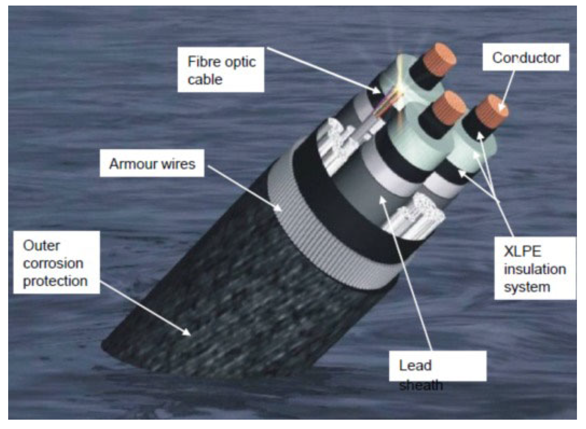
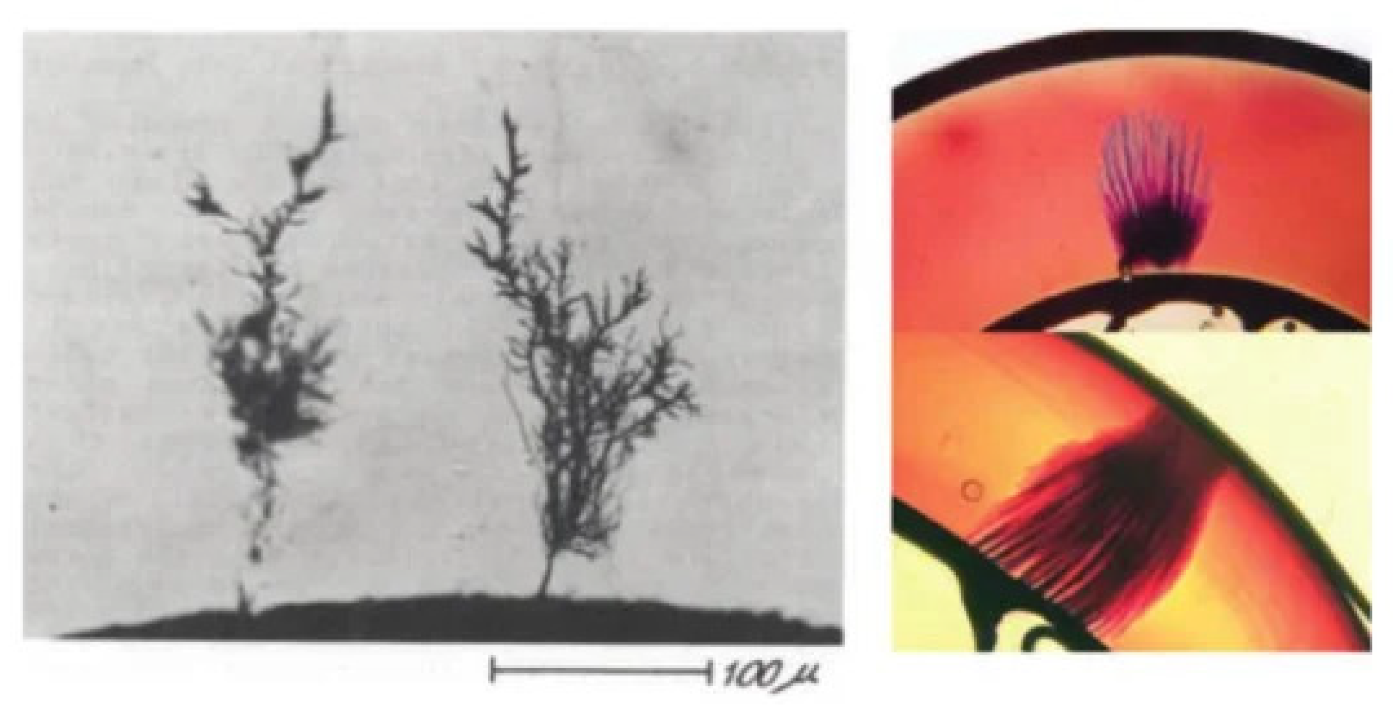
Figure 1 shows the complex structure of submarine power cable. The deterioration phenomena that degrades the service lifespan of these XLPE power cables is know as water treeing. Water-trees are very small voids of a few nano-meters as depicted in Figure 2. Cable manufacturers and power suppliers need to understand the influence of water-trees, their coalescence and their migration towards copper, that may lead to corrosion with the fear of shutdown that will result in an economical catastrophe.
A brief summary of bibliography defines water trees as nanovoids that need a residual humidity within the insulation to propagate (not free water) and do not grow up under low electrical voltage. Water trees are located in the insulation materials (Bow tie tress, the case study of current article) as well as in the interface between the insulator and the screen (Vented trees), from defects that exist at these both areas. During the elaboration process of the insulator, many nanovoids are introduced in the dielectric (stream curing), that absorb humidity and start to coalesce to form water-trees. Water-trees are partially conductive tridimensional structures that look like plumes and are related to polymers crystalline structures. Under the combined effects of high electrical voltage and residual water, water-trees propagate and increase size by a channeling effects that took them generally all the way to the conductor, which starts corroding. The bibliography pertaining to modeling of degradation by water-trees is numerous. Few examples just for reminder, the growth of water tress are heavily influenced by external and internal factors. The external factors (Operational) are when water trees arise during the process of manufacturing, construction and installation [9,10]. Internal factors are the material factors of cables. A lot of publications are available that cover the effects due to external factors on water tree growth, but there is little literature available that addresses internal factors. There is an increase in temperature of the insulator due to rising loads and electrical current, which also triggers the formation of water-tress inside XLPE [11]. Thermal aging influence during operational service was identified to be significant on several properties of the insulation material (electrical, physico-chemical...). Thermal degradation was shown to ease the initiation as well as the propagation of water-trees [9,10]. The same authors used a modeling based on finite element along with Taguchi method to identify and study key-factors that influence the electric field at the tip of water-trees initiated from the outer surface of XLPE cable insulation. Dielectric properties of water-trees as well as the properties of the insulation material were shown to have a heavy influence of the increase of tree tip’s electric field intensity and this influence is higher than tree’s geometrical parameters. The permittivity distribution within the water-tree has also been identified as the key-factor over all others. Accelerated aging by water-trees based on increasing voltage, frequency as well as various techniques of producing artificial water-trees have been used to get insight into the influence of this aging on dielectric properties of the XPLE insulator [12]. It was shown that the electric field at the tip of the water tree is increased due to the increase of both the size and permittivity of the water-tree. However, there remains the question whether accelerated aging is or is not representative of what is going on inside the cable. Lin et al. [13] have modeled the effects of mechanical behavior on the size increase of water-trees, at various temperatures. It was shown that the increase of size of water trees is depending mainly on the mechanical behavior of the insulation material. It was also shown that water tree propagation is slowed by the raise of temperature while reverse mechanism is shown when yield strength is lowered. This adds to the fact that the development of water trees is function of the electric field and residual humidity [14].
The pioneering article [2] that supports current work has suggested a model of the coalescence of two neighbouring nano-voids. It is assumed that plastic deformation of the nanovoids that arise from the combined effects of electrical field and mechanical loading is responsible for two adjacent voids to coalesce, thus promoting the growth of water trees. In this article, the growth of water trees due to internal factors was investigated by considering some special cases.
Using computer modelling and numerical analysis a better understanding of electric field distribution caused by water-treeing mechanism can be gained. Heuristically, a water tree is a nanovoid that propagates under the influence of an electrical field and experimental findings state that the study of water growth rates as a function of polymer morphology, electric field strength and frequency would need very long time [8]. Water voids can be of any shape but for the sake of simplicity, they are considered as ellipsoids [15].
Under the influence of alternating electric field, the XLPE material suffers from continuous Maxwell stress which leads to the fracture of molecular chains [16]. Water voids connect through channels and that advancing in the direction of electric field, which causes degradation of the dielectric strength of insulation [17] and also results in the migration of water-trees to conductor followed by its corrosion with probable shutdown. The range of electric fields considered for this analysis was 10 kV/mm to 100 kV/mm. This was then applied to evaluate the effective plastic strain when water voids are placed in both parallel and perpendicular to the conducting surface. Obviously these two extreme distributions are not the only ones that can exist and there are a plethora of other cases. Nevertheless, our current objective is to set-up a preliminary model that study the effects of the proximity of nano-voids to copper conductor and of the Maxwell forces, as well as these same effects when one moves away gradually from the conductor. This would allow us to better specify the mechanisms when we will consider the random distributions of defects within the insulator. Except its concept, the article is not yet to be applied to industry. In fact, one should keep in mind that experimental aging is extremely tedious, given the very high aging resistance of XPLE. As a matter of fact, many researchers tried to extract results from fast experimental tests although those tests are not representative of “natural” aging. So the scope of current research is precisely to go towards simulation of natural aging of a single phase (not the cable) using numerical modeling. For all work, the depth at the bed sea where the cable is placed is considered to be 800 m (mean depth that was suggested by a cable manufacturer). The effects of water pressure, the external temperature are not studied, at this stage.
The electromechanical modeling is set-up to simulate an electromechanical system before actual system is built to examine physical parameters of the system. The present research was carried out in the electromechanics perspective, using COMSOL Multiphysics. COMSOL Multiphysics is a finite element analysis solver that helps to conduct multiphysics simulations. Each module in the physics interfaces that are available in this platform is fully multiphysics enabled. There are various study capabilities that include stationery, eigen frequency, time-dependent, frequency response, buckling, and parametric studies.

2. Previous Model

In a previous article [2], numerical models were developed that include a 3D Finite Element (FE) analysis of a water void formed inside an insulator, using COMSOL Multiphysics software. In the perspective of this modeling, ellipsoids were considered [2] and the displacement field of these water voids was proven to be function of the applied electric field. At the tips of these water voids (modeled as ellipsoids), the strain is strongly dependent on the relative distance between two neighboring nanovoids and the magnitude of the applied electric field. The model that was proposed was a sort of introduction towards the assessment of ageing of XPLE insulator, which is extremely tough to simulate experimentally. Indeed, XPLE is a very well mastered material and experimental ageing may take decades before delivering meaningful inputs. Such a study is a typical case where appropriate numerical models can bring a strong support to researchers to figure out ageing under coalescence of nanovoids (water-treing).
The initiation and development of water trees is function of the electric field and leftover water substance [2,14]. The varied electric field coupled to the polarization effect shapes water nanovoids into ellipsoids [15]. The application of an electric field actuates high Maxwell stress close the tips of ellipsoidal water voids, resulting in their distortion. Agreeing to [
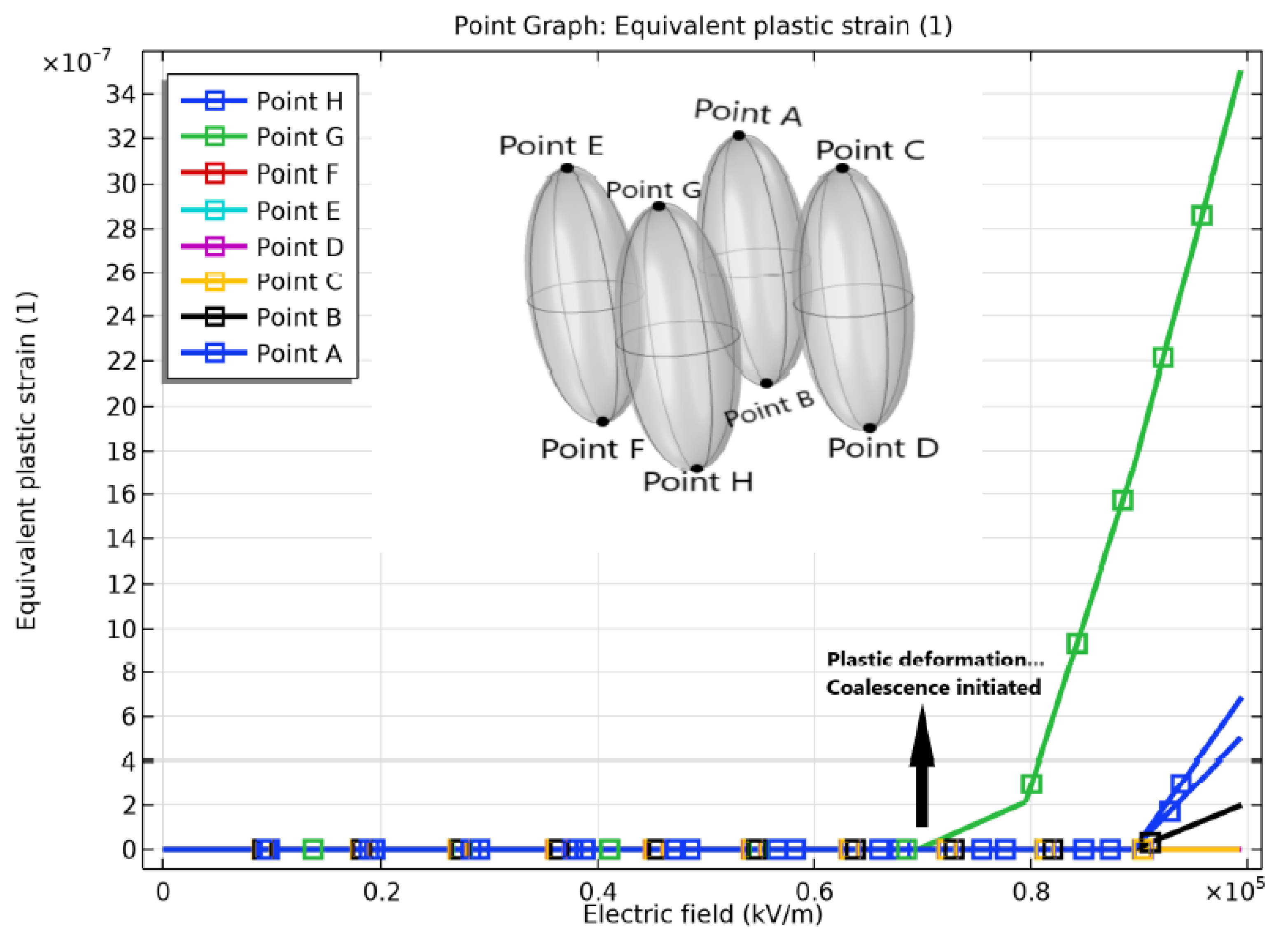
18], moderate electric fields of 10–50 KV/mm don’t cause permanent deformation of water voids, whereas [19] demonstrated that electric fields over 100 KV/mm cause plastic deformation. Hence, in our study an electric field of 50–100 KV/mm was applied to assess the effective plastic strain generated at the tips of water voids. In relation to a numerical study of water treeing in power cable insulation from a mechanical point of view, refs. [20,21] detailed that weariness of insulation caused by dielectro-phoretic stresses around the voids might lead to the development of water trees.
It was appeared [8] that water-trees growth proceeds through coalescence of ellipsoidal-shaped nanovoids. Nanovoids were originating from extrusion process and also generated when cables are under service, time water molecules reach the nanovoids, because excess of humidity. After initiation, water-trees start their migration towards copper which cause corrosion to propagate and damage cables. 
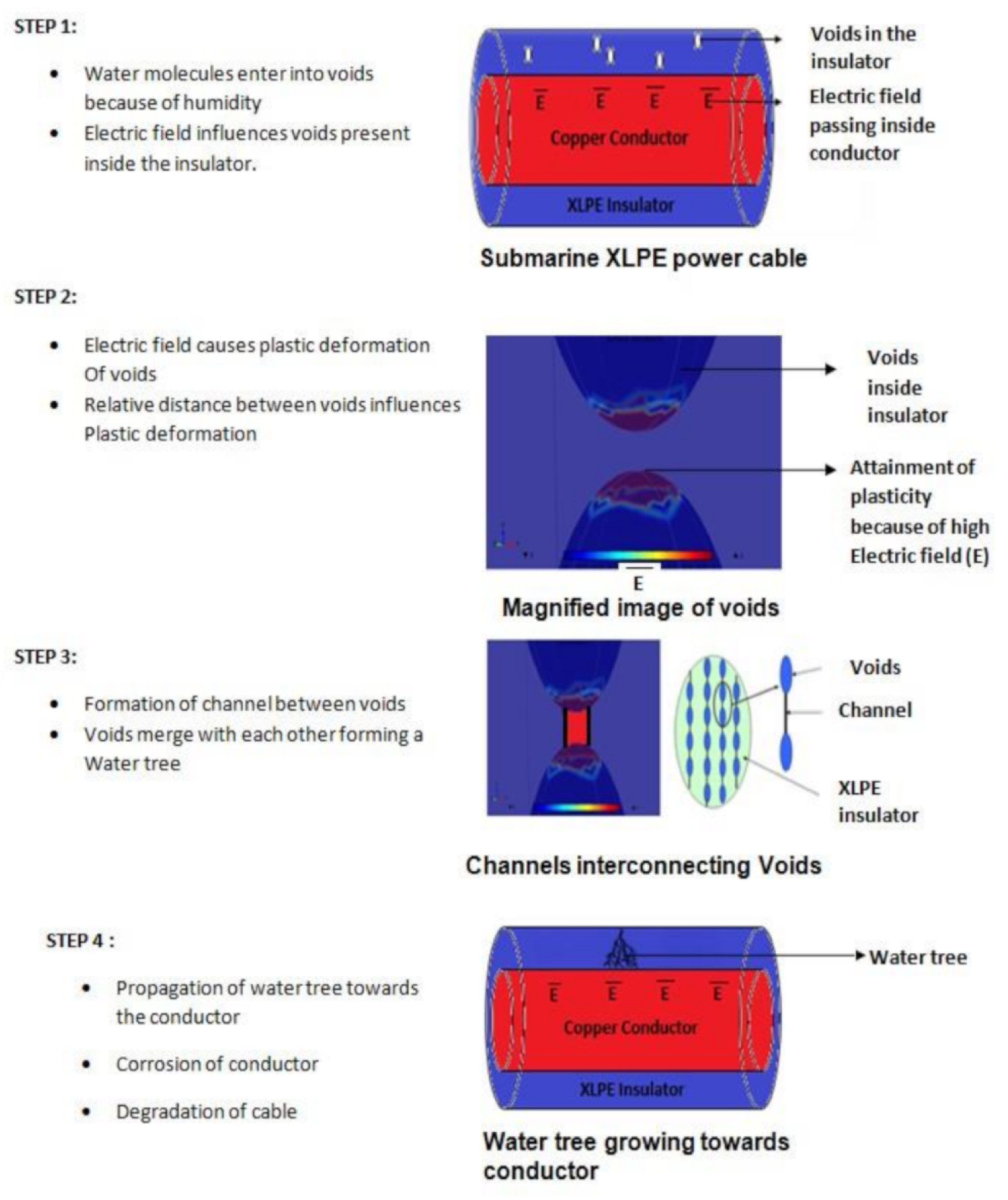
Figure 3 represents the steps involved in the development of water trees. Ref. [
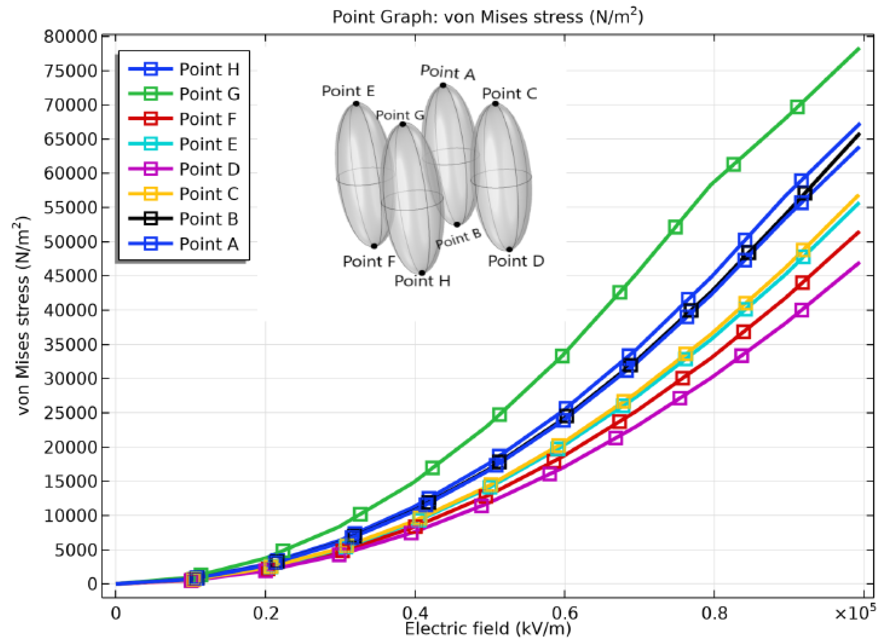
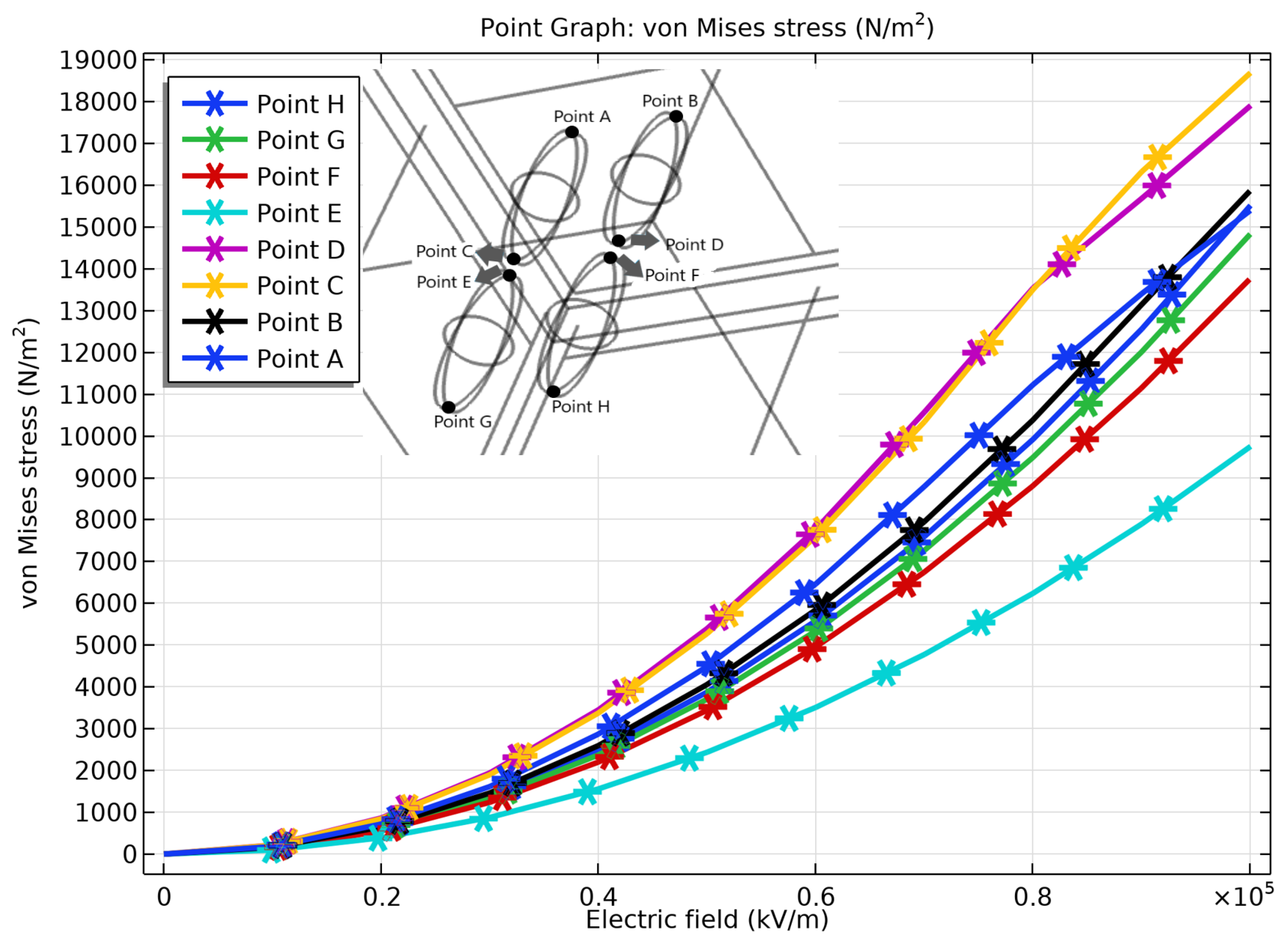
2] proved that Maxwell stress increases as the relative inter-voids distance decreases. That leads to the increase of the Von Mises stress. 
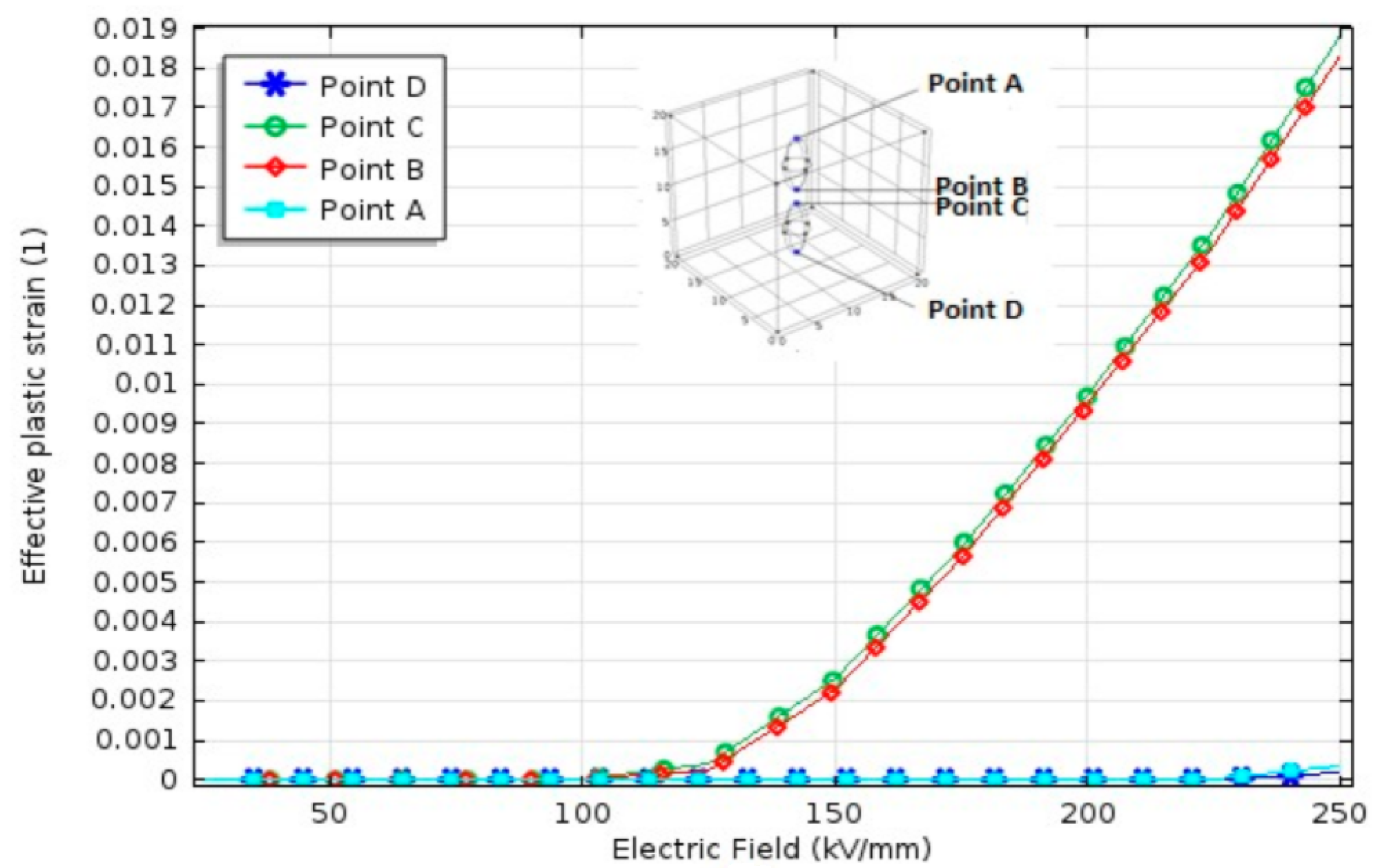
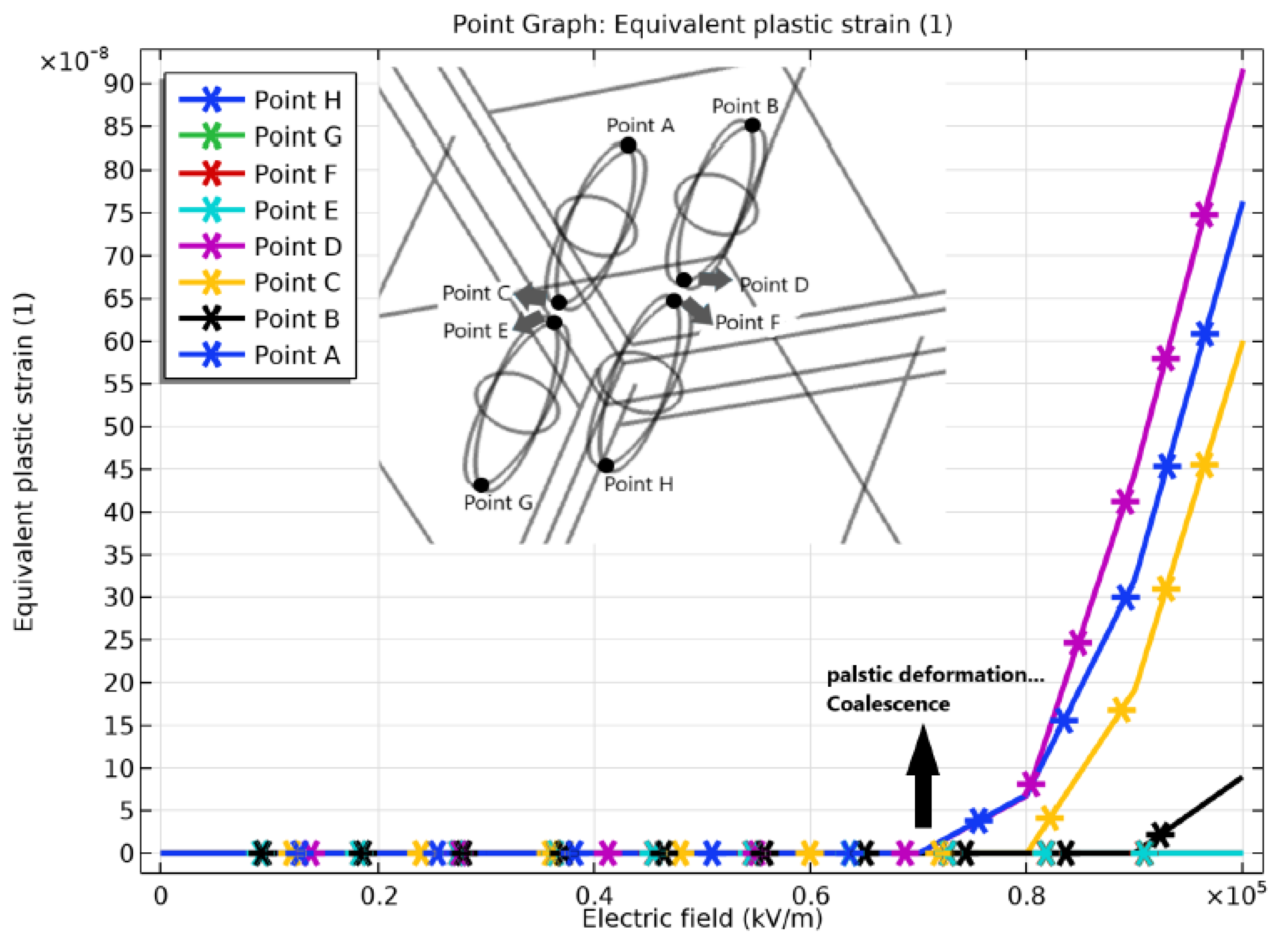
Figure 4 shows the close relationship between the effective plastic strain at the tips of the nanovoids electric field. Typically, it demonstrated that the tips of water nanovoids reaching plasticity with an increase in electric.
The results of [2] shed some light on this juncture, in spite of the fact that significant inquire yet to be done. We noted the significantly affects on the coalescence and formation of water voids with respect to applied electric field and relative distance between two adjacent nanovoids. In the current article, we went a little further to enlarge the research, which may enable generalizing of previous model to coalescence of n voids at the step level of a single phase (not the cable) and examining how these defects initiate corrosion of copper. The continuation of this work is the aim of the current research.

3. Objective of Current Research

The void coalescence in XLPE power cable has a significance with respect to applied electric field and the spacing between the nano-voids [
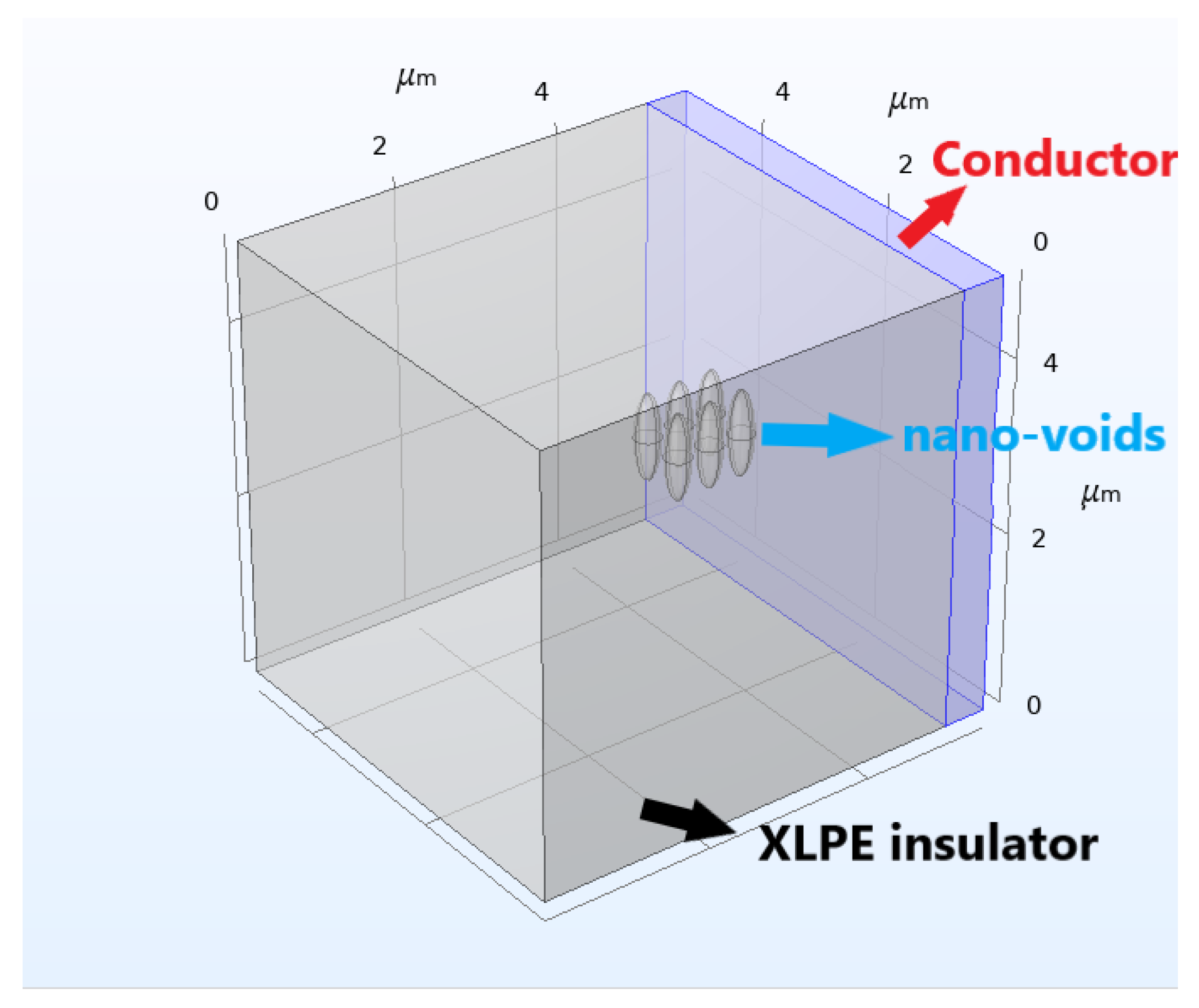
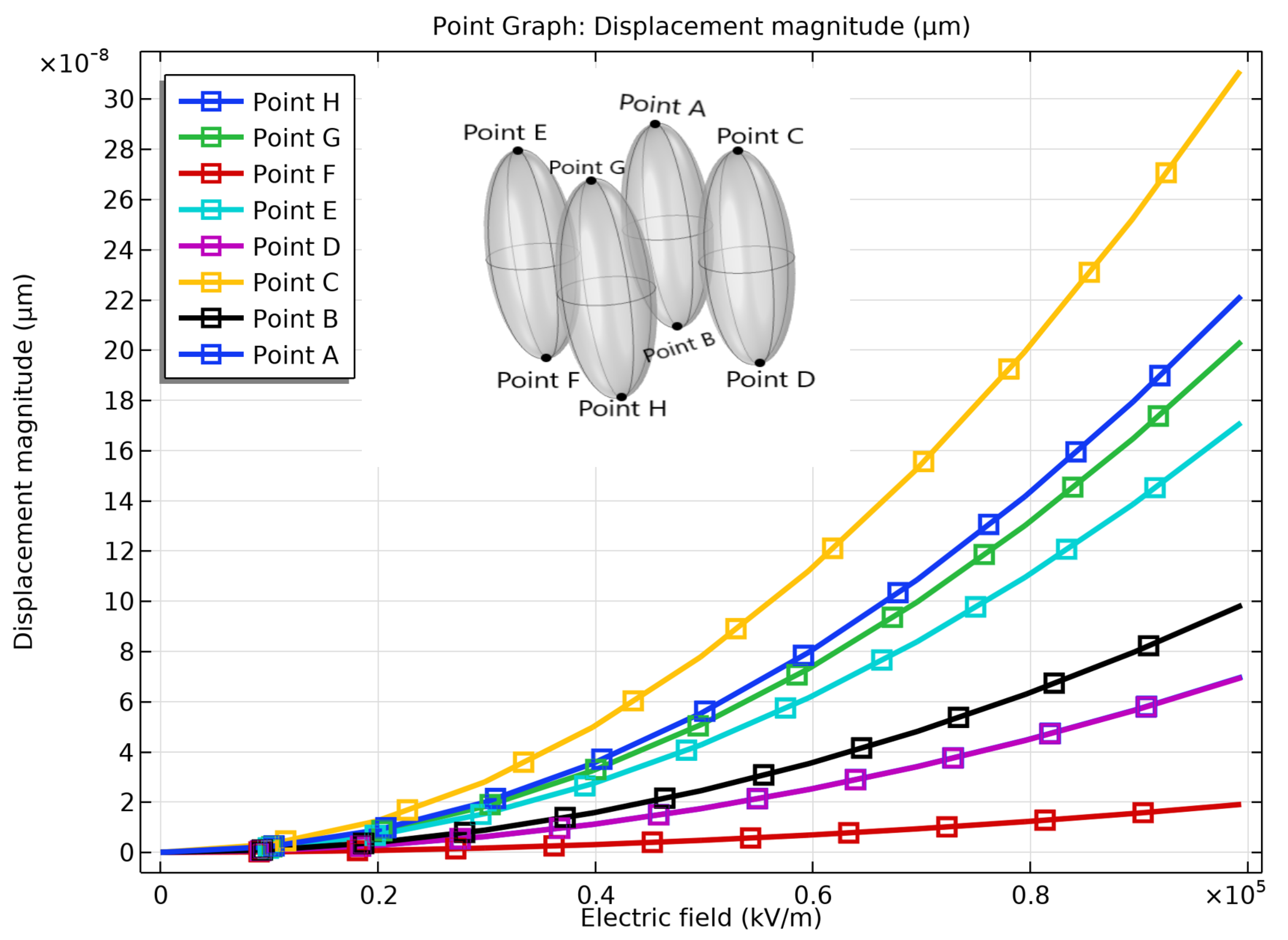
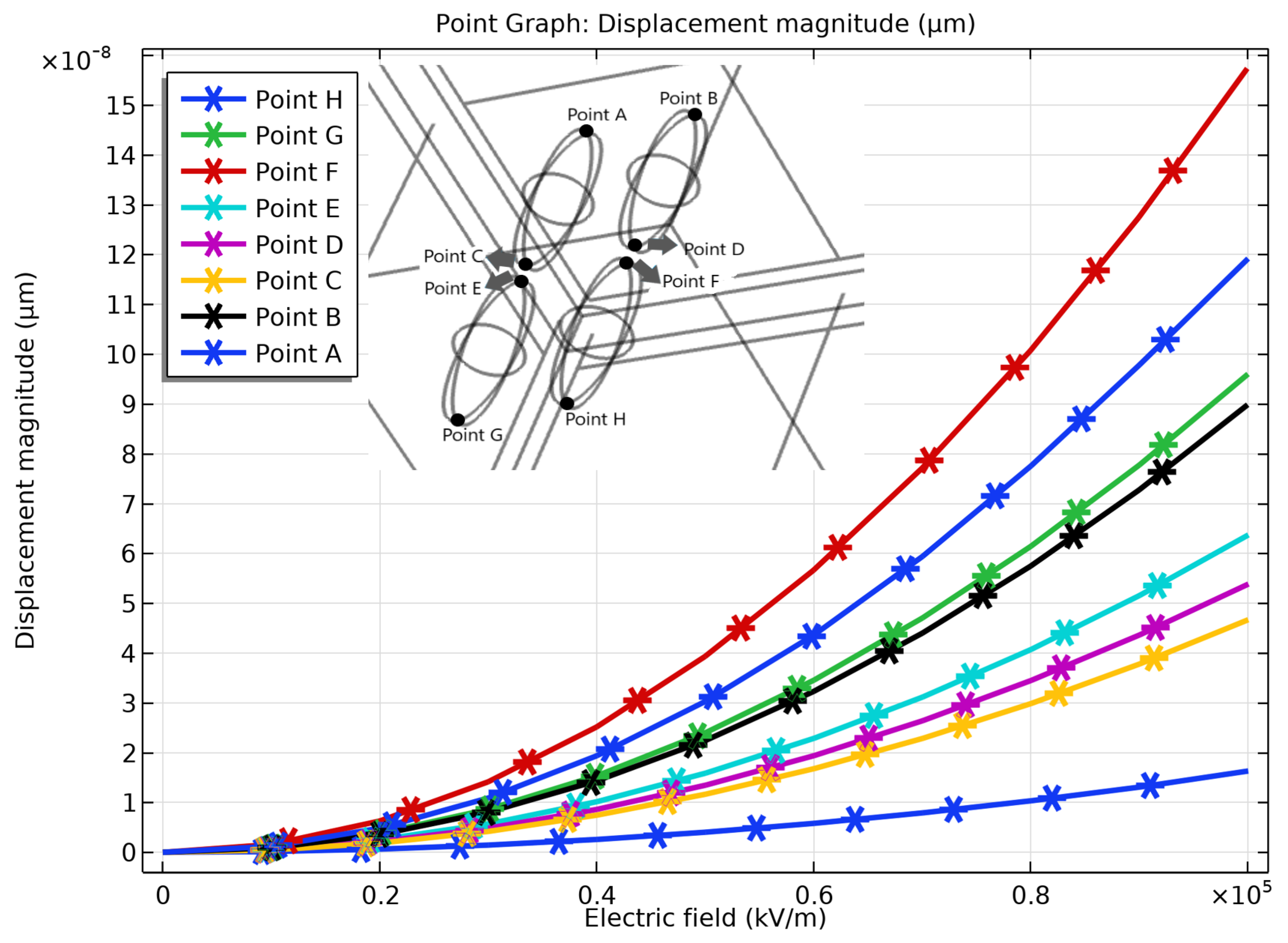
2]. The present work is intended to come up with a way towards the generalization of the coalescence of n nanovoids at the step level of a single phase. For that, a preliminary 3D finite element model was developed. A multi-physics model is presented and simulated the combined effects of mechanical stress and electric field. In an insulator, water voids can occur in random locations but for simplicity, two extreme scenarios were considered. In the first extreme scenario, water voids were placed parallel to the copper surface and close to it, knowing that the distance to copper has influence on plastic deformation of voids. In the second scenario, the water voids were placed perpendicular to copper Surface. For both cases, the idea upstream is to check the effects of Maxwell forces on nanovoids when their distance from copper conductor is varied either when they are aligned horizontally and/or vertically. Figure 5 shows the illustration of this project. The electric field varied from 10 kV/mm to 100 kV/mm.In all the work, he cable is assumed to be at a depth of 800 m and is considered submitted to hydrostatic loading
In the Figure 5, Case 1 represents water voids placed parallel, Case 2 represents water voids placed perpendicular and Case 3 represents random placement of water voids to the electrical conductor. 
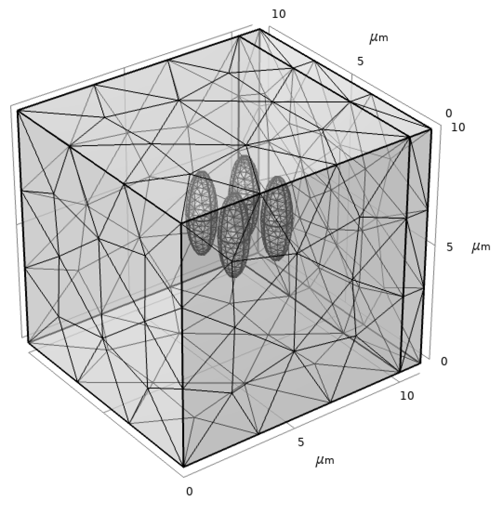
Figure 6 illustrates the one of the extreme cases where nanovoids are placed parallel to the conductor of the single phase considered. The cuboid represents XLPE insulator, which is attached to copper conductor. This model replicates submarine power cables considered at a nano-scale. This article covers the different aspects of the coalescence of nanovoids by preforming the following cases:
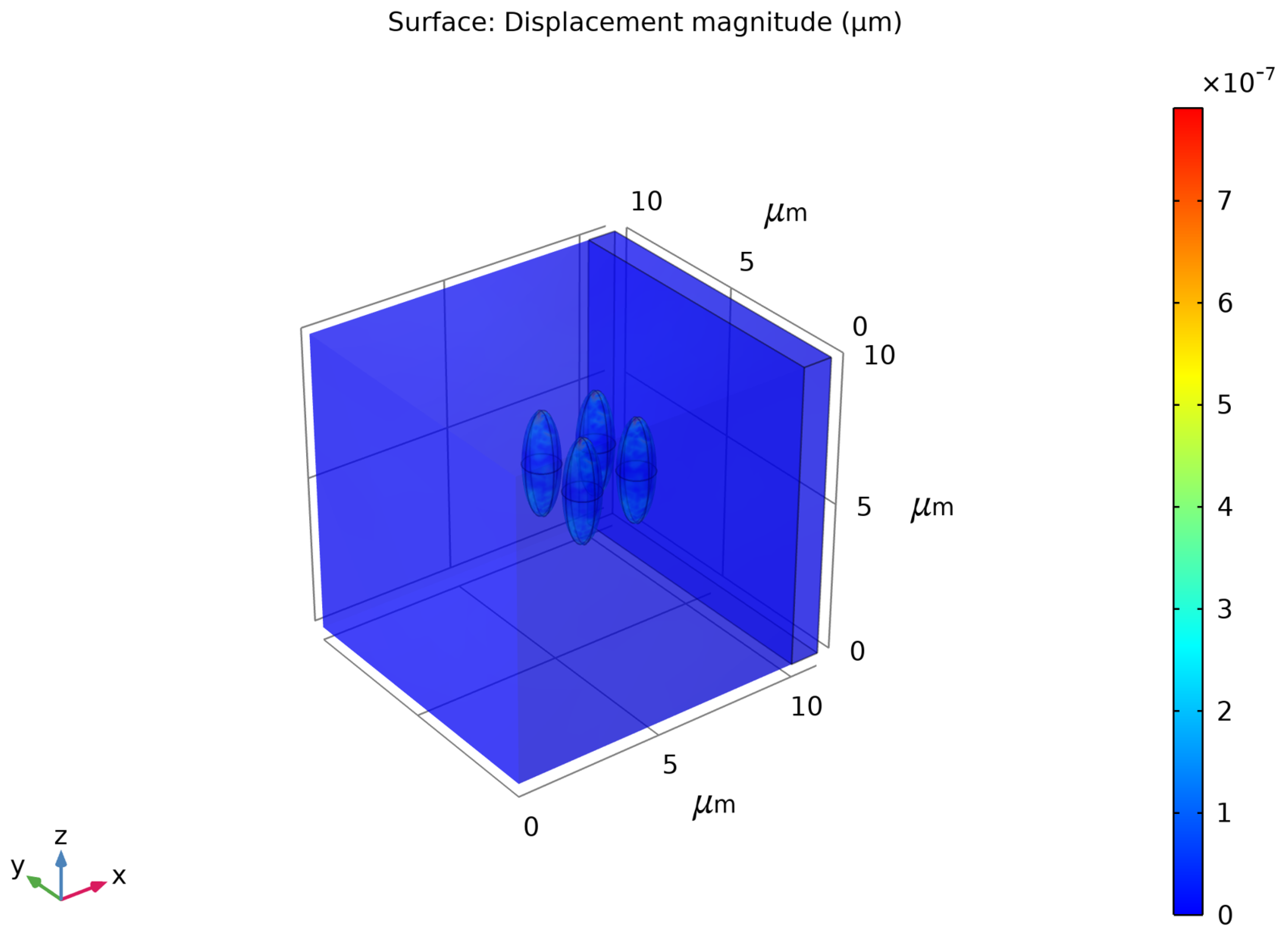
  • calculating the displacement and von Mises stress of water voids placed perpendicular and parallel to the copper surface with varied voltage;
  • studying the plastic deformation of nanovoids placed in both configurations knowing that plastic deformation of void tips is leading to their coalescence, then compare the results.
The Section 4 of this article describes the modeling tools, the Section 5 describes the multiphyics or coupled problem approach to understand the electro-mechanical problem in this juncture and the Section 6 describes the results obtained.

4. Numerical Modeling

4.1. Geometric Parameters

The amount of water content that can be present inside insulator is around 1% to 6% of the total insulation volume [8]. The density is approximately 106 mm−3 [14]. In this work, water void is considered as 0.1 μm. The number of voids present in each scenario was limited to four as it was difficult to run the tests for a large number of voids in the perspective of multi-physics modeling. As shown in the previous section, copper can be represented as an empty cubic cell with conducting properties. The insulator can be represented as a cubic cell in which water voids are presents in the form of ellipsoids. For this study, the geometric parameters for each domain are considered as shown in Table 1.

FE Software

As mentioned earlier, modeling and simulation were carried-out using COMSOL Multiphysics. This solver is most preferred in multiphysics perspective as it provides a wide range of possible operating conditons and physical effects. The current case study was carried-out using electro-mechanics module that is found under the structural mechanics physics tree. For the sake of simplicity for the modeling and analysis, water voids were considered as ellipsoids provided with the suitable materials [2].

4.2. Material Parameters

The material parameters that were used for each domain in this study are shown in Table 2, Table 3 and Table 4.

4.3. Electromechanics Model

A 3D electro-mechanics model is used to describe the deformation of water void at the interface of the conductor and insulator of the single phase considered (not the cable). Initially, a single water void is placed in between the two cubic cells and its deformation was studied with varying electric potential. The equations that governs the electro-mechanics module in COMSOL Multiphysics are:
. σ = F
. D = ρ
Equation (1) is the equilibrium equation of continuum mechanics and Equation (2) is the Gauss law of electricity where σ is the Cauchy stress tensor, F is the body force, D is the electric displacement and ρ is the free charge density. The study was performed to understand the distortion of water voids at their tips. Further, the study was extended to understand the plastic deformation between them. The electric field intensity is the negative of potential gradient as shown in Equation (3). The constitutive equations that relates the electric field intensity and displacement (D) in an insulator is shown in Equation (4).
E = V
D = ϵ 0 ϵ r E
As mentioned earlier plastic deformation of water voids was studied using von Mises yielding criterion. This study was achieved by using plasticity theory. By default, the problem was first set to Linear elastic material and plasticity was added as a sub node(attribute) to it. As we know, in the elastic region, the stress and strain are proportional to each other. At some point, there will be yielding and that is the end of the elasticity. So, we have to specify the initial yield stress. After this behaviour, the model meets perfect plasticity (Figure 7).
In our case, as the electric field increases, von Mises stress also increases, especially at the tips of ellipsoids (i.e., nanovoids). So, to study plasticity of water voids we found a value during simulations where von Mises stress surpasses the yield strength of XLPE. Figure 8 shows the meshing which was used for case 1. The coarse mesh was used for both XLPE and Copper model, a normal mesh was used for ellipsoids.

5. Results and Discussion

To understand the deformation caused due to applied electric field, various simulations were executed to gzt some interesting results. With the increase of electric field up to 250 kV/mm, von Mises stress also gets higher at the tips of water void void. At the tips of two neighboring nanovoids the displacement is a function of their relative distance and on the magnitude of the electric field [2].

5.1. Case 1: Water Voids Placed Parallel to the Copper Surface

As specified above, the first part of this study involves the placement of water voids parallel to copper surface. Since the analysis was carried-out on several 3D voids present in an insulator, to compensate with the computational cost and resources, the study was limited to 100 kV/mm. Initially, the electric potential was provided to observe the displacement of water voids. Then, the electric field was varied between 10 kV/mm to 100 kV/mm. Figure 9 and Figure 10 show the displacement of water voids and electric field distribution inside XLPE of the single phase considered.
When the nano-voids are placed in the direction of electric field they suffer a maximum deformation [2]. The deformation on the voids can also vary concerning the location inside the insulator. Figure 11 shows the deformation as a form of displacement concerning the electric field. As electric field increases the deformation also increases. Points A and C are most likely to be deformed because they were placed nearer to the edge where the influence will be higher.
As shown in the illustration, the points in the figures are the tips of the water voids. The deformation of the voids also depends on their position and their alignment [2]. Generally, for two voids to merge, it involves plastic deformation of the localized at the tips [2]. Now, to study the merging of the material von Mises criterion was used. In a material, plastic deformation is attained due to an external load and that is or electric field. This electric field causes Maxwell stress to act along the voids surfaces.
Figure 12 shows the increase of von Mises stress especially at tips. This is due to the induced Maxwell stress. In this Figure 12 shows that at 80 kV/mm von Mises stress surpasses the yield strength of XLPE.
When Von Mises stress reaches a critical value which can be seen from the Figure 12 water voids experience permanent deformation, 80 × 10 3 Pa. That is, at around 0.8 × 10 5 kV/m (i.e., 80 kV/mm) the plastic deformation is taking place at point G. In the Figure 13 around 0.7 × 10 5 kV/m (i.e., 70 kV/mm) there is a huge shift of the slope in the displacement as the electric filed increases and it shows that initial yield stress required for studying plasticity is 1.4 × 10 10 N/m2. That means, at this critical value, voids experience permanent deformation. And, at electric field 0.5 × 10 5 kV/m the equivalent plastic strain was observed.

5.2. Case 2: Water Voids Placed Perpendicular to the Copper Surface

In this case, water voids were placed perpendicular to Copper. The entire procedure is the same as case 1. As mentioned earlier, the deformation of voids is expressed as the displacement at the tips of water voids, Figure 14.
The deformation of nanovoids at their tips was observed as electric field increased. The affect on water voids due to electric field strictly depends on the placement of nanovoids inside the insulator. As specified earlier, for two voids to merge, it involves plastic deformation of of the tips to take place [2]. Now, to study the failure of the material, von Mises criterion was used. As shown in Figure 15, the nanovoids in this juncture most likely execute permanent deformation and at 19 × 10 3 Pa. Around 0.7 × 10 5 kV/m (i.e., 70 kV/mm) the plastic deformation is taking place at point D and followed by other void tips in XLPE as shown in Figure 16.
The aim of the current research is to observe the plastic deformation at tips in both cases and as the electric field increases the merging of localized zones are most likely expand forming water trees. The spacing considered in the first scenario was different from the second as the modeled configuration is different. The spacing considered was 2 μm for the first scenario and whereas 1.8 μm for the second. In this analysis spacing was not varied in any of the cases.
As specified in the Section 2, the void coalescence was studied at the tips of water voids while setting the critical distance between the two adjacent water voids(i.e., nano voids) as 2 μm and at an applied electric field of 225 kV/mm. In both cases, it we can observe the cause of plastic deformation by high Von Mises stress and this Von Mises stress was influenced by an amplified electric field. The localized damage will be achieved if the order of plasticity increases. The plastic deformation caused by high von Mises stress obtained from the influence of an amplified electric field at the tips of voids. From both the cases, the results obtained helped us to visualize plastic deformation of nanovoids placed at two extreme cases inside an insulating material.
The plastically-deformed zones expand with increase of the electric field intensity and the merging of voids will be initiated. This kind of model is interesting because it is difficult to perform experimental analysis. As a top view of the modeling, this research tends to indicate that numerical simulation of ageing by water trees can be approximated correctly. The parameters that are critical for this mechanism to be activated can be accurately identified and varied so that enabling insightful conclusions to be out-comed, which can help to figure out how ageing proceeds in such critical structures. Of course, we are still far from a model that can be used by engineers. This will need to upgrade the model by introducing many other variables such that the random distribution of nanovoids, the variation of external temperature, the external pressure, the movement of cables... This effort is currently under way.

6. Conclusions

Submarine power cables are expected to last 20 years without maintenance to be considered technologically and economically reliable, enough. One of the main issues facing this target is the development of what is called commonly water-trees (nanometer-sized flaws) that form within XLPE insulators and then migrate towards copper, thus leading to its corrosion and further to shut-down. Therefore, cable manufacturers are keen to understand the possible parameters that influence the growth of water-trees. The results achieved in this article were based on generalizing coalescence to nanovoids placed parallel and perpendicular to the conductor of the single phase considered and gave a preliminary understanding on the issues regarding the electrical breakdown. Two extreme cases, where water voids placed parallel and perpendicular to the copper surface, were considered. The simulations were run up to 100 kV/mm to understand the plastic deformation especially at the water void’s tips, which leads to coalescence. The spacing between water voids was kept minimum. As a future work, more variables that were not considered in current article will be introduced (shape and distribution of voids, chemical aspects of voids merging, effects of electric discharge, effect of water pressure...). Also, finer meshing can be implemented to get more precise results. The coalescence at tips of water voids was observed at 70 kV/mm for the first scenario, whereas 80 kV/mm for the second scenario which is matching with the actual functional values. Based on this, one can conclude that with the presence of n nanovoids, coalescence can happen at a much faster rate that suspected, with a possible shutdown. As mentioned earlier, technically nano-voids can be present in any configuration inside an insulator but two extreme cases were considered for the sake of preliminary investigation. Future work can consider randomly distributed nanovoids and check for the conditions of their merging. Significant research remains to be done on the investigation of coalescence of n nanovoids with different densities and temperature involved.

Author Contributions

D.-H.M. is in charge of supervision, conceptualization, methodology, resources and review editing, M.S. and N.A. are in charge of software, validation and formal analysis, C.V. and B.P.-J. are in charge of investigation. All authors have read and agreed to the published version of the manuscript.

Funding

Funding was provided by The French Research Agency (ANR) under the Contract Flow-Cam Project.

Acknowledgments

This research has been conducted within Flow-Cam FLOW CAM (FLoating Offshore Wind turbine CAble Monitoring) Project in the framework of Martera Era-Net Cofund. The French National Research Organizeation, ANR, provided funding to this work. I-Site Future provided a master-grant to SM. MDH would like to thank the funders for their support.

Conflicts of Interest

The authors declare no conflict of interest.

References

  1. Drissi-Habti, M.; Raman, V.; Khadour, A.; Timorian, S. Fiber Optic Sensor Embedment Study for Multi-Parameter Strain Sensing. Sensors 2017, 17, 667. [Google Scholar] [CrossRef] [PubMed] [Green Version]
  2. Drissi-Habti, M.; Raj-Jiyoti, D.; Vijayaraghavan, S.; Fouad, E. Numerical Simulation for Void Coalescence (Water Treeing) in XLPE Insulation of Submarine Composite Power Cables. Energies 2020, 13, 5472. [Google Scholar] [CrossRef]
  3. Raman, V.; Drissi-Habti, M.; Guillaumat, L.; Khadhour, A. Numerical simulation analysis as a tool to identify areas of weakness in a turbine wind-blade and solutions for their reinforcement. Compos. Part B Eng. 2016, 103, 5472. [Google Scholar] [CrossRef] [Green Version]
  4. Famakin, S.; Kim, C. Modeling for underground cable water tree growth dynamics. J. Power Energy Eng. 2019, 7, 51. [Google Scholar] [CrossRef] [Green Version]
  5. Hinrichsen, P.F.; Houdayer, A.; Belhadfa, A.; Crine, J.P.; Pelissou, S.; Cholewa, M. A localized trace element analysis of water trees in XLPE cable insulation by micro-PIXE and EDX. IEEE Trans. Electr. Insul. 1988, 23, 971–978. [Google Scholar] [CrossRef]
  6. Matine, A.; Drissi-Habti, M. On-Coupling Mechanical, Electrical and Thermal Behavior of Submarine Power Phases. Energies 2019, 12, 1009. [Google Scholar] [CrossRef] [Green Version]
  7. The European Subsea Cables Association. Available online: http://escaeu.org (accessed on 26 January 2022).
  8. Teyssedre, G.; Laurent, C. Advances in high-field insulating polymeric materials over the past 50 years. IEEE Electr. Insul. Mag. 2013, 29, 26–36. [Google Scholar] [CrossRef]
  9. Kim, C.; Jin, Z.; Huang, X.; Jiang, P.; Ke, Q. Investigation on water treeing behaviors of thermally aged XLPE cable insulation. Polym. Degrad. Stab. 2007, 13, 92. [Google Scholar] [CrossRef]
  10. Kim, C.; Duan, J.; Huang, X.; Kim, S.; Jiang, P.; Kim, H.; Hyon, S. Numerical analysis on water treeing deterioration of XLPE cable insulation using combination of FEM and Taguchi method. Eur. Trans. Electr. Power 2010, 13, 749–759. [Google Scholar] [CrossRef]
  11. Rajagopala, K. Electric and Thermal Properties of Wet Cable 10 kV and 15 kV. TELKOMNIKA Indones. J. Electr. Eng. 2012, 10, 1904–1916. [Google Scholar]
  12. Radu, I.; Acedo, M.; Filippini, J.C.; Notingher, P.; Ftutos, F. The effect of water treeing on the electric field distribution of XLPE. Consequences for the dielectric strength. IEEE Trans. Dielectr. Electr. Insul. 2000, 7, 860–868. [Google Scholar] [CrossRef]
  13. Lin, S.; Zhou, K.; Li, Y.; Meng, P. Water-tree propagation in a wide temperature range insight into the role of mechanical behavior of cross-linked poly-ethlylene (XPLE) Material. Polymers 2021, 13, 40. [Google Scholar] [CrossRef] [PubMed]
  14. Ross, R. Inception and propagation mechanisms of water treeing. IEEE Trans. Dielectr. Electr. Insul. 1998, 5, 660–680. [Google Scholar] [CrossRef]
  15. Capaccioli, S.; Lucchesi, M.; Casalini, R.; Rolla, P.A.; Bona, N. Effect of water inclusions on charge transport and polarization in porous media. IEEE Trans. Dielectr. Electr. Insul. 2001, 8, 454–460. [Google Scholar] [CrossRef]
  16. Tao, W.; Ma, Z.; Wang, W.; Liu, J.; Zhou, K.; Li, T.; Huang, M. The mechanism of water tree growth in XLPE cables based on the finite element method. In Proceedings of the 2016 IEEE International Conference on High Voltage Engineering and Application (ICHVE), Chengdu, China, 19–22 September 2016; pp. 1–4. [Google Scholar]
  17. Boggs, S.A.; Mashikian, M.S. Role of semiconducting compounds in water treeing of XLPE cable insulation. IEEE Electr. Insul. Mag. 1994, 10, 23–27. [Google Scholar] [CrossRef]
  18. Crine, J.-P. Influence of electro-mechanical stress on electrical properties of dielectric polymers. IEEE Trans. Dielectr. Electr. Insul. 2001, 12, 791–800. [Google Scholar] [CrossRef]
  19. Sakamoto, M.; Yahagi, K. Influence of High Electric Fields on Capacitance Measurements in PE. Jpn. J. Appl. Phys. 1980, 19, 253–259. [Google Scholar] [CrossRef]
  20. Wang, Z.; Marcolongo, P.; Lemberg, J.A.; Panganiban, B.; Evans, J.W.; Ritchie, R.O.; Wright, P.K. Mechanical fatigue as a mechanism of water tree propagation in TR-XLPE. IEEE Trans. Dielectr. Electr. Insul. 2012, 19, 321–330. [Google Scholar] [CrossRef]
  21. Meziani, M.; Mekhaldi, A.; Teguar, M. Impact of presence of water tree and microcavities on the electric field distribution in XLPE insulation (ICEE). In Proceedings of the 2015 4th International Conference on Electrical Engineering, Boumerdes, Algeria, 13–15 December 2015; pp. 1–5. [Google Scholar]
Figure 1. The components of a submarine power cable, Copyright ESCA [7].
Energies 15 01844 g001
Figure 2. The Electrical and water treeing shown in the polyethylene insulated cable in the left. Electrical trees are grown from field-enhancing defects at the insulation interface, in the right water trees growing from the conductor screen. Taken from [8].
Energies 15 01844 g002
Figure 3. Schematic representation of steps involved in the growth of water trees [2].
Energies 15 01844 g003
Figure 4. Effective plastic strain at the tips of ellipsoids with increasing electric field (50–250 kV/mm) and decrease in distance between points B and C at distance 0.5 μm.
Energies 15 01844 g004
Figure 5. Illustration of the possible cases where voids can be placed in an insulator for the analysis.
Energies 15 01844 g005
Figure 6. CASE 1: Illustration of the case where nanovoids are put parallel to copper.
Energies 15 01844 g006
Figure 7. Stress-Strain relationship.
Energies 15 01844 g007
Figure 8. Meshing in Case 1.
Energies 15 01844 g008
Figure 9. Deformation of voids at their tips. Note the colors of the nanovoids, especially red that shows plastic deformation stage.
Energies 15 01844 g009
Figure 10. Electric field distribution inside XPLE.
Energies 15 01844 g010
Figure 11. Deformation vs electric field.
Energies 15 01844 g011
Figure 12. Von Mises stress vs. electrical field.
Energies 15 01844 g012
Figure 13. Plastic strain vs. electric field.
Energies 15 01844 g013
Figure 14. Deformation as a function of Electric field for case 2.
Energies 15 01844 g014
Figure 15. Von Mises stress vs. Electric field for case 2.
Energies 15 01844 g015
Figure 16. Equivalent plastic strain vs Electric field for case 2.
Energies 15 01844 g016
Table 1. Modeling parameters.
Name of the DomainValueUnit
XPLEl = 10, b = 10, h = 10μm
Copperl = 10, b = 10, h = 10μm
Water void (ellipsoid)a = 0.6, b = 0.6, c = 1.8μm
Table 2. XPLE Properties [2].
NameValueUnit
Young’s Modulus3.5GPa
Relative permittivity2.31
Poisson’s Ratio0.3kg/m3
Density9301
Electrical conductivity 1 × 10 15 S/m
Initial yield stress18MPa
Table 3. Properties of water-voids [2].
NameValueUnit
Electrical conductivity--
Relative permittivity801
Table 4. Properties of Copper [6].
NameValueUnit
Young’s Modulus112GPa
Relative permittivity11
Poisson’s Ratio0.301
Density of Copper9400kg/m3
Electrical conductivity 58.7 × 10 6 S/m
Publisher’s Note: MDPI stays neutral with regard to jurisdictional claims in published maps and institutional affiliations.

