
Experimental Study on Bearing Characteristics of Multi-Strata Anchorage System


Abstract
:1. Introduction
2. Engineering Background and Methods
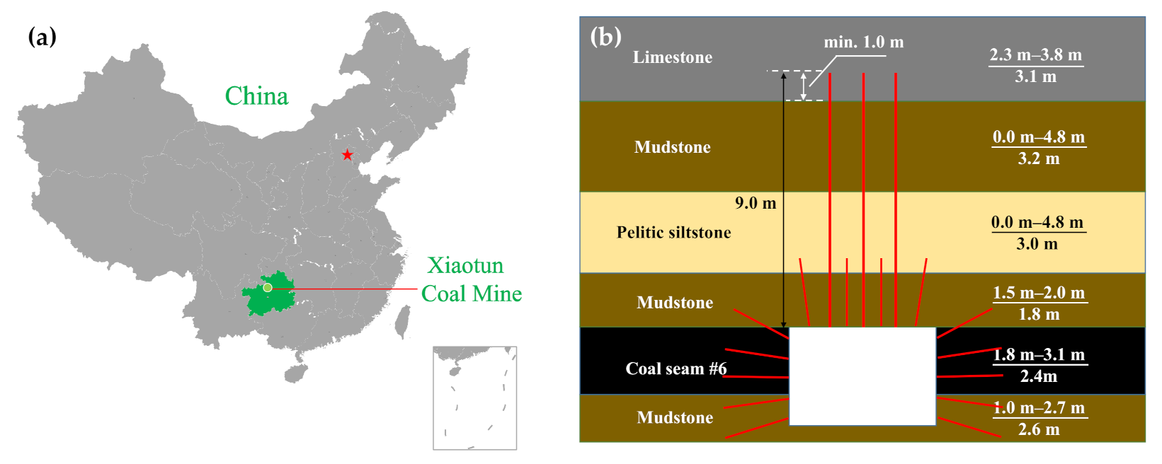
2.1. Background
- (1)
- The rock cable is unduly long, and the bolting operation is time-consuming and laborious. The tension force of the rock cable is limited at the field of the coal mine and the corresponding prestress cannot be applied to the rock cable due to its blindly increased length. As a result, the surrounding rock cannot be effectively controlled by the rock cable in a certain range, and the active support effect of the rock cable is weakened.
- (2)
- The suspension range is unduly wide. The rock cable in the limestone provides a large anchoring force, but the weak rock layer in the lower part is too thick. If the control effect is poor, the deformation and damage of the separation layer will gradually accumulate, and the rock cable is under great stress. In this case, the load born by the cable is far beyond the weight of the strata, making it easier for the anchorage system to fail.
2.2. Test Scheme
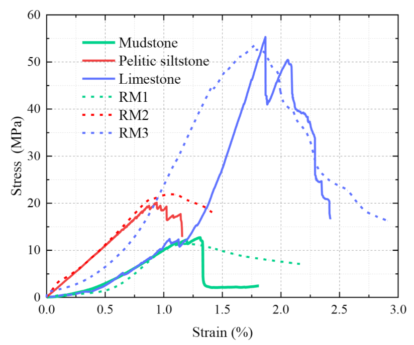
2.2.1. Determining the Strength of Rock-Like Material
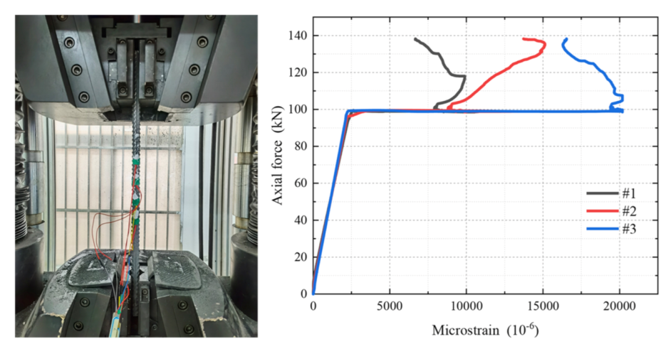
2.2.2. Fabrication of Force Measuring Bolt and Calibration of Load Strain
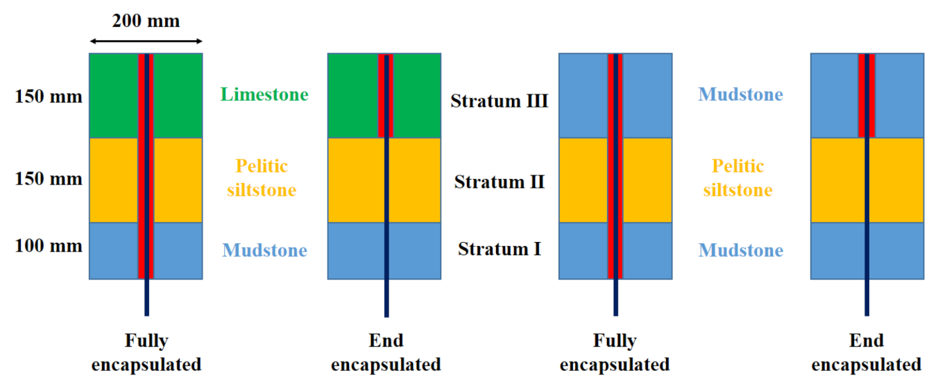
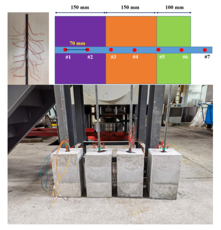
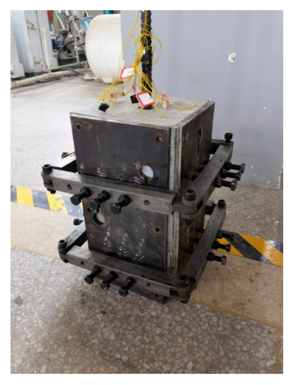
2.2.3. Preparation of the Specimens
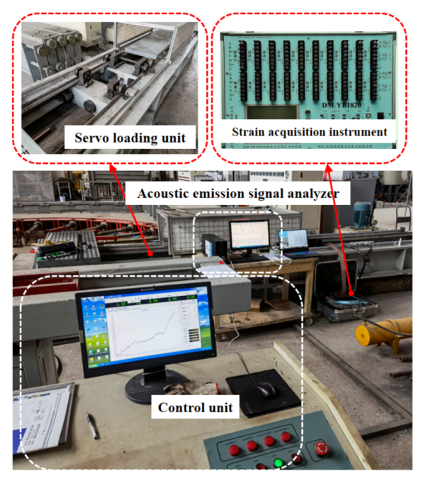
2.2.4. Test Arrangement
3. Test Results
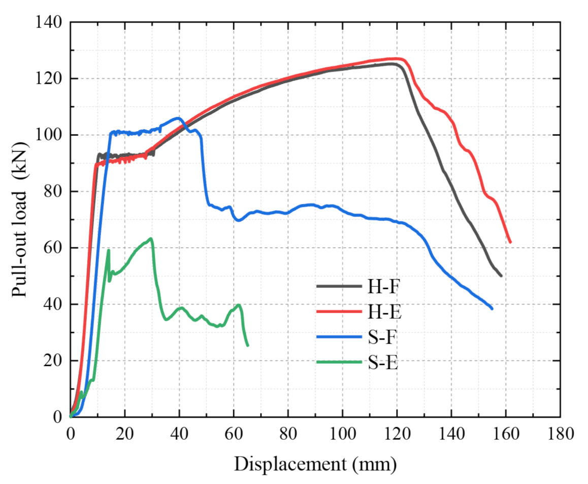
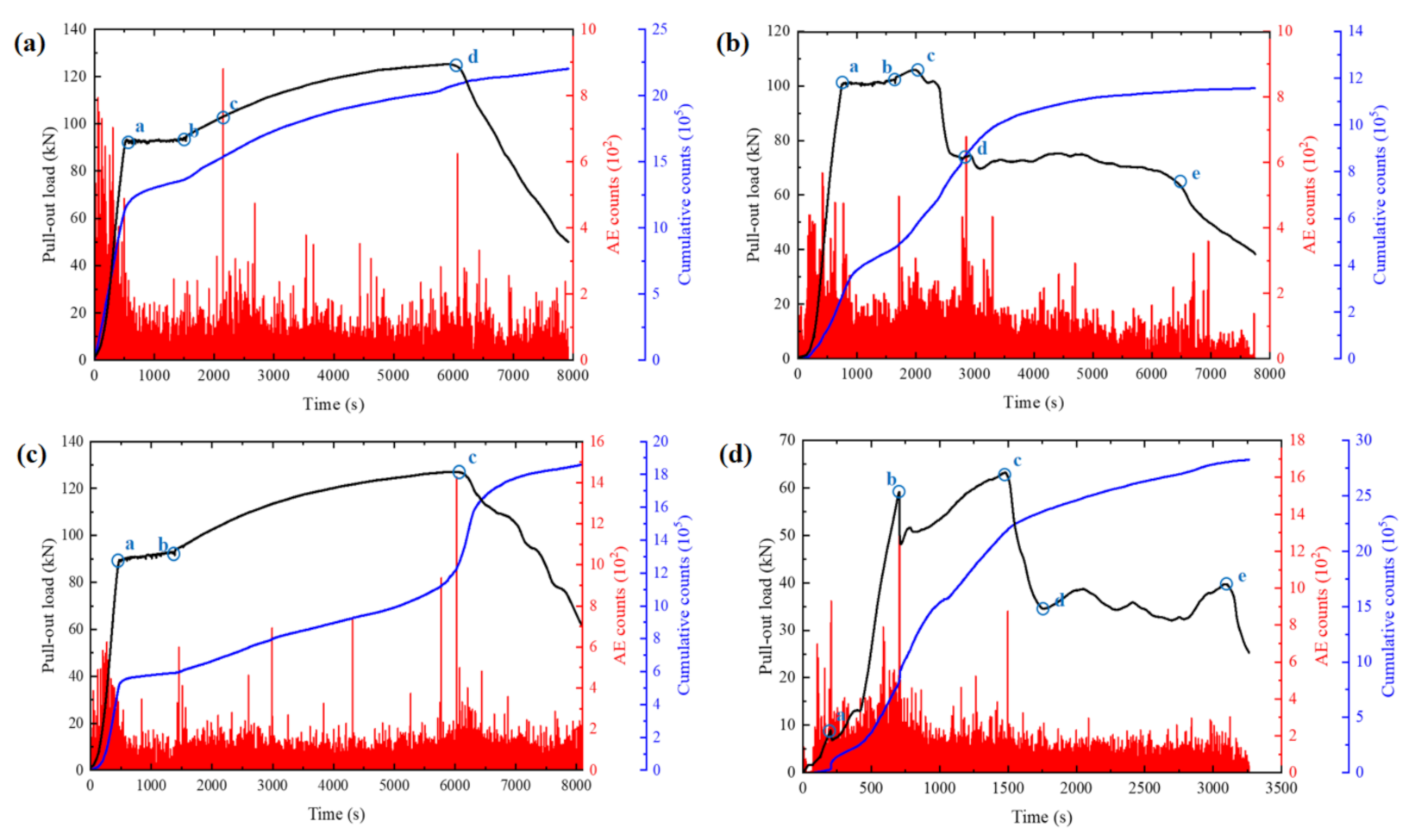
3.1. Pull-Out Load
3.2. Axial Force and Shear Stress Distribution
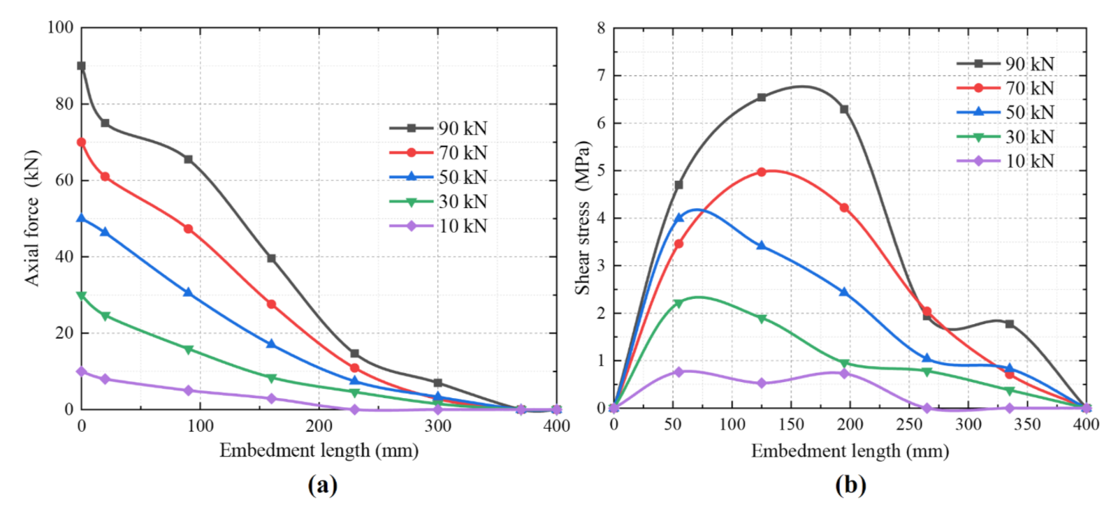
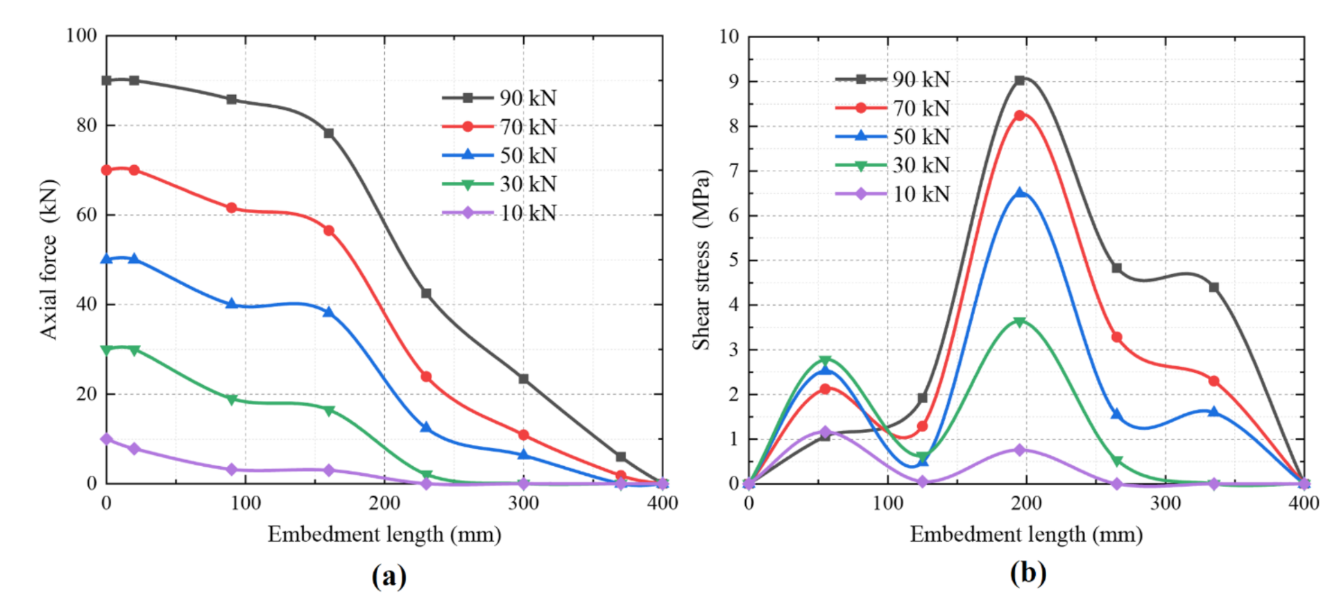
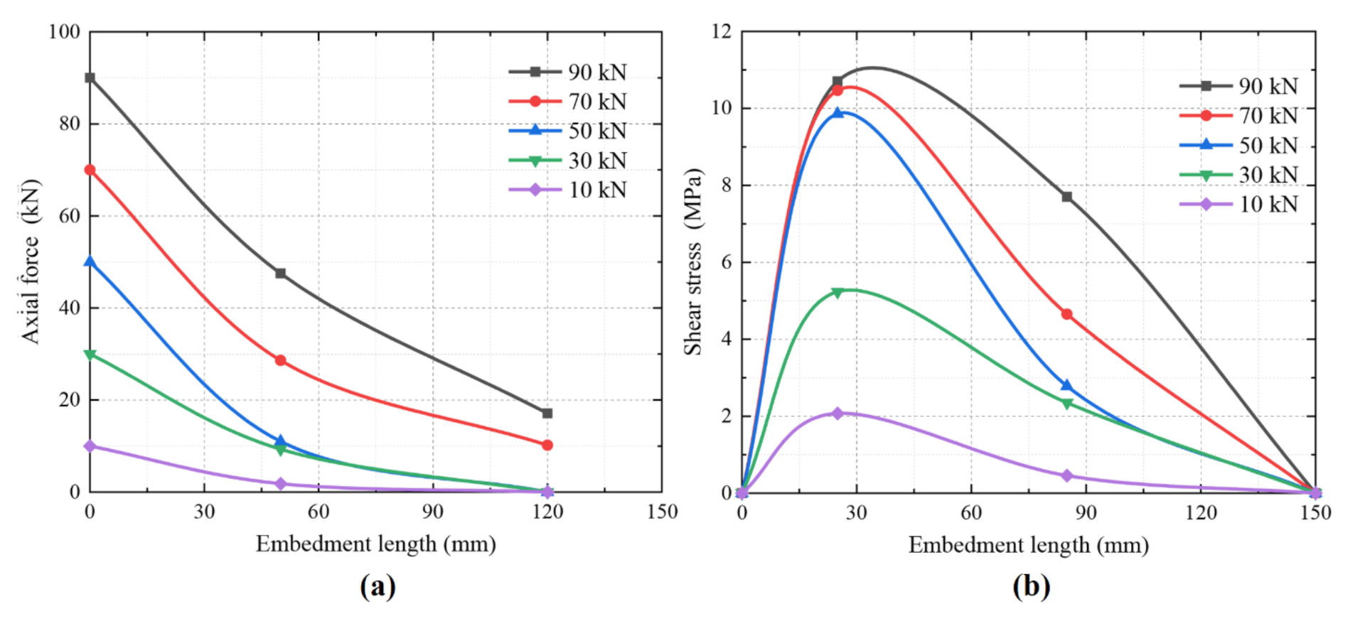
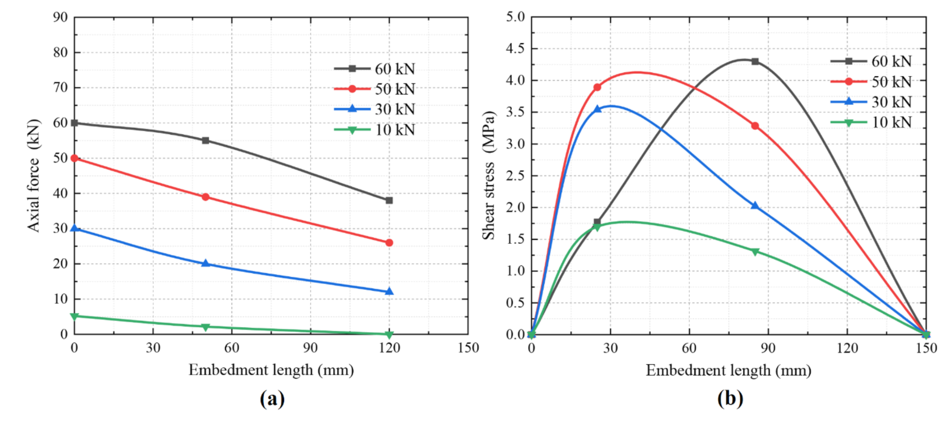
3.2.1. Axial Force Distribution
3.2.2. Shear Stress Distribution
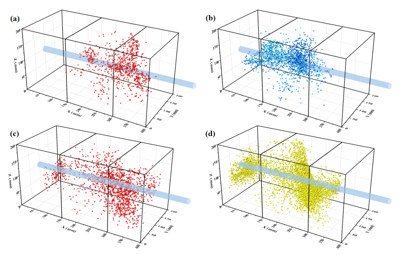
3.3. AE Responses
4. Discussion
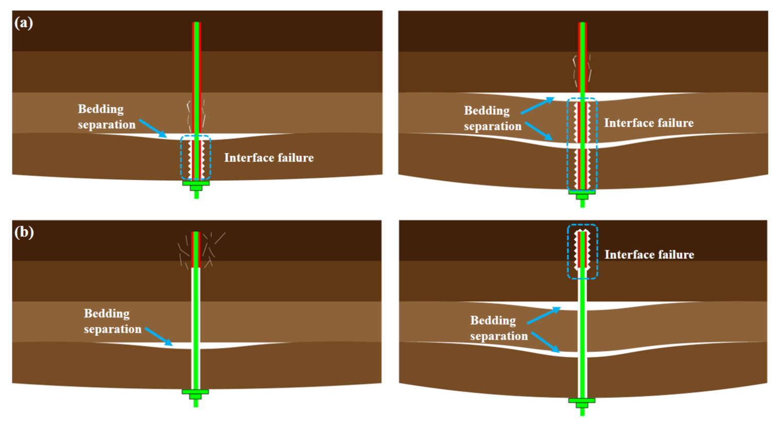
4.1. Failure Process of Anchoring Interface in Fully Encapsulated Bolt
4.2. Anchorage Reliability Analysis
5. Conclusions
- (1)
- The change of the mechanical properties of the surrounding rock has an important impact on the shear strength of the Agent-Rock interface. Under the end encapsulation condition, the load-bearing performance of the anchorage system in hard rock is much higher than that in soft rock; although the load-bearing performance of the anchorage system in hard rock still surpasses that in the soft rock, full-length encapsulation can significantly reduce the gap of anchoring force between them.
- (2)
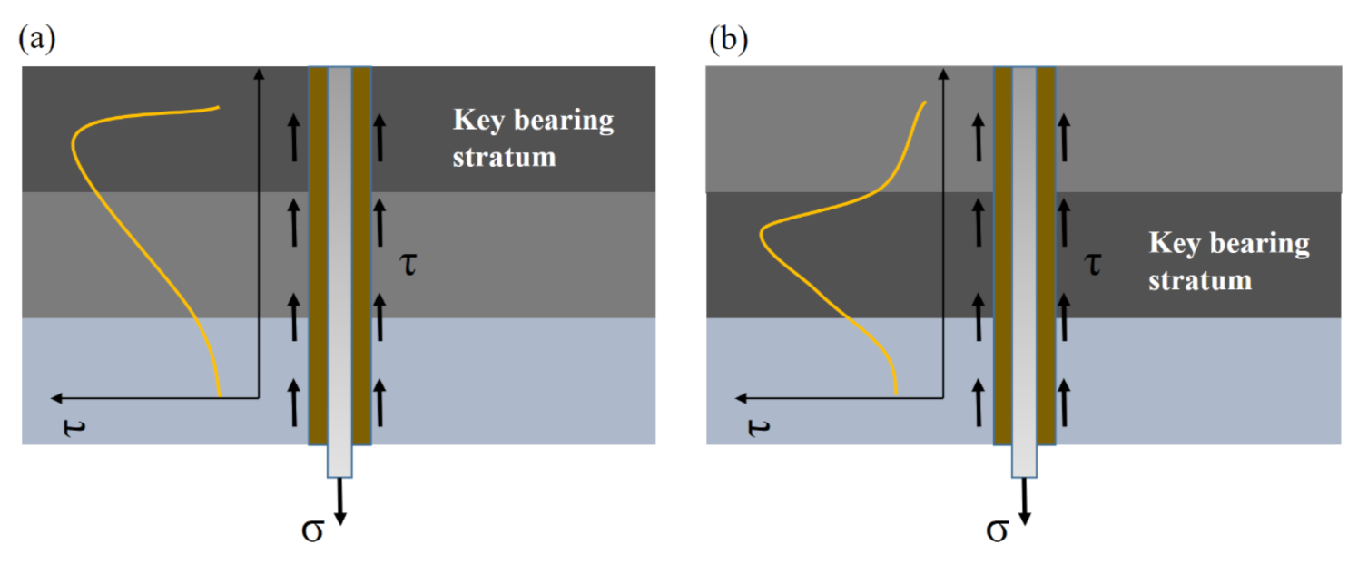
- When the fully encapsulated system is subject to a tension load, the axial force of the bolt gradually decreases from shallow to deep, and the peak value of shear stress gradually increases and is transferred to the deeper part. The shear stress distribution of HRFES represents a unimodal pattern, while that of the SRFES looks multimodal, and the shear stress is at a low ebb at the strata interface. We also found that before reaching the ultimate pull-out load, the peak interfacial shear stress of the HRFES located in Stratum III, while the interfacial shear stress peak of the SRFES stopped at Stratum II.
- (3)
- It can be found that in the case of multi-strata, the key bearing stratum of the fully encapsulated system is the rock stratum with the strongest total interfacial shear strength. The location of the key bearing stratum also affects the mechanical response of the anchoring interface. The deeper the location of the key bearing stratum, the more reliable the anchorage system will be. This research finding can provide suggestions for selecting a reasonable bolt length and anchoring method for rock bolt support in coal mine roadways.
Author Contributions
Funding
Institutional Review Board Statement
Informed Consent Statement
Data Availability Statement
Conflicts of Interest
References
- Hou, C.J.; Gou, P.F. Mechanism study on strength enhancement for the rocks surrounding roadway supported by bolt. Chin. J. Rock Mech. Eng. 2000, 3, 342–345. [Google Scholar]
- Zhang, N.; Han, C.L.; Xie, Z.Z. Theory and efficient support technology of continuous beam roof control in coal roadway. J. Min. Form. Control Eng. 2019, 1, 48–55. [Google Scholar]
- Xie, Z.Z.; Zhang, N.; Feng, X.W. Investigation on the evolution and control of surrounding rock fracture under different supporting conditions in deep roadway during excavation period. Int. J. Rock Mech. Min. Sci. 2019, 123, 104122. [Google Scholar] [CrossRef]
- Li, G.; Hu, Y.; Tian, S.M.; Ma, W.B.; Huang, H.L. Analysis of deformation control mechanism of prestressed anchor on jointed soft rock in large cross-section tunnel. Bull. Eng. Geol. Environ. 2021, 80, 9089–9103. [Google Scholar] [CrossRef]
- Kang, H.P.; Cui, Q.L.; Hu, B.; Wu, Z.G. Analysis of Anchorage Properties and Influencing Factors of Resin Bolts. J. China Coal Soc. 2014, 39, 1–10. [Google Scholar]
- Xie, H.P.; Gao, F.; Ju, Y. Research and Exploration of Deep Rock Mass Mechanics. Chin. J. Rock Mech. Eng. 2015, 34, 2161–2178. [Google Scholar]
- Xie, Z.Z.; Zhang, N.; Han, C.L.; An, Y.P. Research on principle and application of cross-boundary anchoring of thick layer of coal roadway roof. Chin. J. Rock Mech. Eng. 2021, 40, 1195–1208. [Google Scholar]
- Gao, M.Z.; Xie, J.; Gao, Y.N.; Wang, W.Y.; Li, C.; Yang, B.G.; Liu, J.J.; Xie, H.P. Mechanical behavior of coal under different mining rates: A case study from laboratory experiments to field testing. Int. J. Min. Sci. Technol. 2021, 31, 825–841. [Google Scholar] [CrossRef]
- Zhu, C.; He, M.C.; Jiang, B.; Qin, X.Z.; Yin, Q.; Zhou, Y. Numerical investigation on the fatigue failure characteristics of water-bearing sandstone under cyclic loading. J. Mt. Sci. 2021, 18, 3348–3365. [Google Scholar] [CrossRef]
- Wu, Y.Z. Research on application of full-length prestressed anchoring strong support system. Coal Sci. Technol. 2011, 39, 27–30. [Google Scholar]
- Cai, Y.; Esaki, T.; Jiang, Y. An analytical model to predict axial load in grouted rock bolt for soft rock tunneling. Tunn. Undergr. Space Technol. 2004, 19, 607–618. [Google Scholar] [CrossRef]
- Ma, S.; Nemcik, J.; Aziz, N. An analytical model of fully grouted rock bolts subjected to tensile load. Constr. Build. Mater. 2013, 49, 519–526. [Google Scholar] [CrossRef]
- Li, D.; Masoumi, H.; Hagan, P.C. Experimental and analytical study on the mechanical behaviour of cable bolts subjected to axial loading and constant normal stiffness. Int. J. Rock Mech. Min. Sci. 2019, 113, 83–91. [Google Scholar] [CrossRef]
- Martín, L.B.; Tijani, M.; Hadj-Hassen, F. Assessment of the bolt-grout interface behaviour of fully grouted rockbolts from laboratory experiments under axial loads. Int. J. Rock Mech. Min. Sci. 2013, 63, 50–61. [Google Scholar] [CrossRef]
- Ma, S.; Zhao, Z.; Nie, W. An analytical model for fully grouted rockbolts with consideration of the pre- and post-yielding behavior. Rock Mech. Rock Eng. 2017, 50, 3019–3028. [Google Scholar] [CrossRef]
- Singh, P.; Spearing, A.J.S. An improved analytical model for the elastic and plastic strain-hardening shear behaviour of fully grouted rockbolts. Rock Mech. Rock Eng. 2021, 54, 3909–3925. [Google Scholar] [CrossRef]
- Wang, Y.J.; Wu, Z.M.; Zheng, J.J. 3D analytical investigation on the overall pullout behavior of grouted anchorages in presence of shear failure of grout. Eng. Fail. Anal. 2020, 109, 104249. [Google Scholar] [CrossRef]
- He, L.; An, X.M.; Zhao, Z.Y. Fully Grouted Rock Bolts: An Analytical Investigation. Rock Mech. Rock Eng. 2015, 48, 1181–1196. [Google Scholar] [CrossRef]
- Wang, Q.; Qin, Q. Study and engineering application on the bolt-grouting reinforcement effect in underground engineering with fractured surrounding rock. Tunn. Undergr. Space Technol. 2019, 84, 237–247. [Google Scholar] [CrossRef]
- Chen, J.H.; He, F.L.; Zhang, S.B. A study of the load transfer behavior of fully grouted rock bolts with analytical modelling. Int. J. Min. Sci. Technol. 2020, 1, 105–109. [Google Scholar] [CrossRef]
- Cui, L.; Sheng, Q.; Dong, Y.; Ruan, B.; Xu, D.D. A quantitative analysis of the effect of end plate of fully-grouted bolts on the global stability of tunnel. Tunn. Undergr. Space Technol. 2021, 114, 104010. [Google Scholar] [CrossRef]
- Li, D.; Li, Y.C.; Chen, J.H.; Masoumi, H. An analytical model for axial performance of rock bolts under constant confining pressure based on continuously yielding criterion. Tunn. Undergr. Space Technol. 2021, 113, 103955. [Google Scholar] [CrossRef]
- Chen, Y. Experimental study and stress analysis of rock bolt anchorage performance. J. Rock Mech. Geotech. Eng. 2014, 6, 428–437. [Google Scholar] [CrossRef]
- Chen, Y.; Li, C.C. Performance of fully encapsulated rebar bolts and D-Bolts under combined pull-and-shear loading. Tunn. Undergr. Space Technol. 2015, 45, 99–106. [Google Scholar] [CrossRef]
- Zuo, J.; Wen, J.; Li, Y. Investigation on the interaction mechanism and failure behavior between bolt and rock-like mass. Tunn. Undergr. Space Technol. 2019, 93, 103070. [Google Scholar] [CrossRef]
- Aziz, N.; Craig, P. Factors influencing the quality of encapsulation in rock bolting. Rock Mech. Rock Eng. 2016, 49, 3189–3203. [Google Scholar] [CrossRef]
- Ahmet, T. Effect of mineral admixture types on the grout strength of fully-grouted rockbolts. Constr. Build. Mater. 2017, 145, 376–382. [Google Scholar]
- Li, C.C.; Kristjansson, G.; Høien, A.H. Critical embedment length and bond strength of fully encapsulated rebar rockbolts. Tunn. Undergr. Space Technol. 2016, 59, 16–23. [Google Scholar] [CrossRef] [Green Version]
- Høien, A.H.; Li, C.C.; Zhang, N. Pull-out and Critical Embedment Length of Grouted Rebar Rock Bolts-Mechanisms When Approaching and Reaching the Ultimate Load. Rock Mech. Rock Eng. 2021, 54, 1431–1447. [Google Scholar] [CrossRef]
- Kılıc, A.; Yasar, E.; Celik, A.G. Effect of grout properties on the pull-out load capacity of fully grouted rock bolt. Tunn. Undergr. Space Technol. 2002, 17, 355–362. [Google Scholar] [CrossRef]
- Feng, X.; Zhang, N.; Yang, S. Mechanical response of fully bonded bolts under cyclic load. Int. J. Rock Mech. Min. Sci. 2018, 109, 138–154. [Google Scholar] [CrossRef]
- Li, Y.Z.; Liu, C.H. Experimental study on the shear behavior of fully grouted bolts. Constr. Build. Mater. 2019, 223, 1123–1134. [Google Scholar] [CrossRef]
- Erion, L.; Erion, P. A pioneer in-situ investigation on the bearing capacity and failure causes of real scale fully grouted rockbolts. Constr. Build. Mater. 2021, 310, 124826. [Google Scholar]
- Du, Y.L.; Feng, G.R.; Kang, H.P.; Zhang, Y.J.; Zhang, X.H. Effects of steel fiber grout on the mechanical performance and failure characteristics of fully grouted bolts. Structures 2021, 33, 1096–1106. [Google Scholar] [CrossRef]
- Li, Y.Z.; Tannant, D.D.; Pang, J.J.; Su, G.S. Experimental and analytical investigation of the shear resistance of a rock joint held by a fully-grouted bolt and subject to large deformations. Transp. Geotech. 2021, 31, 100671. [Google Scholar] [CrossRef]
- Saadat, M.; Taheri, A. Effect of Contributing Parameters on the Behaviour of a Bolted Rock Joint Subjected to Combined Pull-and-Shear Loading: A DEM Approach. Rock Mech. Rock Eng. 2020, 53, 383–409. [Google Scholar] [CrossRef]
- Teymen, A.; Kilic, A. Effect of grout strength on the stress distribution (tensile) of fully-grouted rockbolts. Tunn. Undergr. Space Technol. 2018, 77, 280–287. [Google Scholar] [CrossRef]
- Lu, T.K.; Dai, Y.H. The working characteristics of full-length anchor bolts in the layered roof of mining roadway. Chin. J. Rock Mech. Eng. 2010, 29, 3329–3335. [Google Scholar]
- Zhang, N.; Li, G.C.; Kan, J.G. Influence of weak interlayer layer on the roof of coal roadway on the stability of bolt support structure. Geomechanics 2011, 32, 2753–2758. [Google Scholar]
- Panek, L. Principles of Reinforcing Bedded Mine Roof With Bolts; US Department of the Interior, Bureau of Mines: Washington, DC, USA, 1956. [Google Scholar]
- Wong, R.H.C.; Chau, K.T. Analysis of crack coalescence in rock-like materials containing three flaws—Part I: Experimental approach. Int. J. Rock Mech. Min. Sci. 2001, 38, 909–924. [Google Scholar] [CrossRef]
- Sagong, M.; Bobet, A. Coalescence of multiple flaws in a rock-model material in uniaxial compression. Int. J. Rock Mech. Min. Sci. 2002, 39, 229–241. [Google Scholar] [CrossRef]
- Xin, C.; Zhihong, L.; Xi, P. Deformability characteristics of jointed rock masses under uniaxial compression. Int. J. Min. Sci. Technol. 2012, 22, 213–221. [Google Scholar]
- Yang, X.X.; Jing, H.W.; Tang, C.A. Effect of parallel joint interaction on mechanical behavior of jointed rock mass models. Int. J. Rock Mech. Min. Sci. 2017, 92, 40–53. [Google Scholar] [CrossRef]


| Specimen | Proportion (Cement: Sand: Water) | UCS/MPa | Elastic Modulus /GPa |
|---|---|---|---|
| RM1 (for limestone) | 6:1:2 | 53.5 | 5.3 |
| RM2 (for politic siltstone) | 2:4:1.1 | 21.9 | 2.5 |
| RM3 (for mudstone) | 1.2:5.6:1 | 11.4 | 1.6 |
| Specimen | Embedment Length | Stratum III | Specimen | Embedment Length | Stratum III |
|---|---|---|---|---|---|
| H-F-1 | 400 mm | Limestone | S-F-1 | 400 mm | Mudstone |
| H-F-2 | 400 mm | Limestone | S-F-2 | 400 mm | Mudstone |
| H-F-3 | 400 mm | Limestone | S-F-3 | 400 mm | Mudstone |
| H-E-1 | 150 mm | Limestone | S-E-1 | 150 mm | Mudstone |
| H-E-2 | 150 mm | Limestone | S-E-2 | 150 mm | Mudstone |
| H-E-3 | 150 mm | Limestone | S-E-3 | 150 mm | Mudstone |
Publisher’s Note: MDPI stays neutral with regard to jurisdictional claims in published maps and institutional affiliations. |
© 2022 by the authors. Licensee MDPI, Basel, Switzerland. This article is an open access article distributed under the terms and conditions of the Creative Commons Attribution (CC BY) license (https://creativecommons.org/licenses/by/4.0/).
Share and Cite
An, Y.; Zhang, N.; Zhao, Y.; Wang, W.; Guo, F. Experimental Study on Bearing Characteristics of Multi-Strata Anchorage System. Energies 2022, 15, 1581. https://doi.org/10.3390/en15041581
An Y, Zhang N, Zhao Y, Wang W, Guo F. Experimental Study on Bearing Characteristics of Multi-Strata Anchorage System. Energies. 2022; 15(4):1581. https://doi.org/10.3390/en15041581
Chicago/Turabian StyleAn, Yanpei, Nong Zhang, Yiming Zhao, Weiwei Wang, and Feng Guo. 2022. "Experimental Study on Bearing Characteristics of Multi-Strata Anchorage System" Energies 15, no. 4: 1581. https://doi.org/10.3390/en15041581