Article

Analysis of Controlled Driving and Spreading Behavior of Molten Pool in Cold Metal Transfer

1
School of Mechanical and Automotive Engineering, Shanghai University of Engineering Science, Shanghai 201620, China
2
School of Materials Science and Engineering, Shanghai Jiao Tong University, Shanghai 200240, China
*
Author to whom correspondence should be addressed.
Energies 2022, 15(4), 1575; https://doi.org/10.3390/en15041575
Submission received: 25 November 2021 / Revised: 31 December 2021 / Accepted: 5 January 2022 / Published: 21 February 2022

Abstract

:
The controlled short-circuit transfer is used to control the heat input of the molten pool and the base metal in the cold metal transfer welding process, including droplet formation, droplet transfer and molten pool flow. Based on the influence of arc pressure on the surface of the molten pool, droplet impact and residual energy on the flow behavior of the molten pool, this research proposes the arc pressure driving model, the droplet impact driving model and the residual energy transfer model on the molten pool surface respectively, and on this basis, a theoretical model of controlled driving and spreading of the cold metal transition bath is proposed. The theoretical relationship between the surface shape of the keyhole and the driving force, and the relationship between the surface shape of the molten pool and the welding current are established. The model accurately predicts the formation width and contact angle of the molten pool in a specific interval, which can better control the welding process and geometry.

1. Introduction

In the welding process, the internal flow of the molten pool is the main factor that determines the final fusion shape of the weld, the solidification structure and the formation of defects [1]. Researchers analyzed the characteristics of molten pool vibration under different penetration depths from two aspects: the surface vibration of the molten pool and the flow of molten metal in the molten pool [2]. Researchers quantitatively described the formation trend of weld hump under different welding parameters, and predicted the formation of weld hump [3]. Additionally further analyzed the formation mechanism of the hump in the fusion zone from the perspective of fluid movement, that is, increase the welding current to accelerate the penetration of the molten pool and improve energy efficiency [4]. At the same time, the research results show that the thermal expansion of liquid metal is the main reason for the bulging of the surface of the molten pool [5].
The keyhole behavior of the molten pool is a key factor that determines the stability of the plasma arc welding process and the quality of the weld. It is particularly important to study the relationship between weld size and welding current, welding speed and plasma gas flow [6]. Studies believe that a larger downward eddy current and a smaller upward eddy current can ensure a stable and efficient welding process and fewer weld defects [7]. Studies have found that ultrasonic vibration changes the shape of the keyhole, steepens the slope of the front and back walls of the keyhole, and significantly reduces the flow rate of liquid metal [8]. The energy distribution of the keyhole in the plasma arc welding process has an important influence on the final quality of the weld, under the influence of arc pressure and shear stress, the energy will not accumulate on the surface of the keyhole, but will be transported to the rear of the molten pool along with the molten metal [9]. The formation of the penetrating keyhole helps to escape excess energy from the bottom of the keyhole and prevents the bottom of the keyhole from being unstable due to excessive concentration of energy at the bottom of the keyhole [10]. Research has shown that both the arc pressure-driven molten pool deformation and the shear stress-driven molten pool deformation are the reasons for the formation of small holes, and the first mechanism is particularly important [11].
The depression of the molten pool surface is caused by the arc pressure that affects the flow of liquid metal. Under the same current level, the pulse arc pressure will produce a larger weld pool depression. The research results show that the pulsed arc produces a large penetration force, a large temperature difference in the depth direction, a large temperature gradient at the edge of the molten pool, and a small temperature gradient at the center [12]. Studies believe that arc shear stress is the main driving force to promote the free surface deformation of the molten pool and the reflow of liquid metal, which masks the influence of the surface tension gradient [13]. Another study believes that arc pressure and arc shear stress have a significant promotion effect on the formation of molten pool defects, and the surface tension gradient plays a major role in inhibiting the formation of defects [14]. At the same time, researchers have revealed the vibration behavior of the arc plasma and the flow inside the molten pool during the pulsed GTAW process, as an electromagnetic fluid dynamic system, the arc plasma and the molten pool have a fast response to changing currents [15]. As the gas flow increases, the arc cross-sectional area is compressed and the length is extended, the arc penetration capability increases with the increase of the gas flow [16].
The controlled short-circuit transfer process is used to control the heat input of the molten pool and the base metal, including droplet formation, droplet transfer and molten pool formation [17]. Scholars have studied the influence of arc shape and droplet transition behavior on the internal force distribution in the molten pool [18]. Studies have found that the molten droplets are fully fused in the molten pool, and the momentum of the molten droplets will push the molten pool down [19]. Simultaneous simulation results show that the momentum transferred from the falling droplets to the bottom of the molten pool will cause the phenomenon of finger penetration [20]. In the transverse velocity component, the impact of droplet impact and the tension gradient is greater, and in the vertical velocity component, the droplet impact effect is dominant [21]. Furthermore, the droplet transition affects the velocity field of the molten pool, especially the area near the bottom of the molten pool [22]. Therefore, this research fully considers the influence of arc pressure, droplet impact and residual energy on the flow process of the molten pool, and proposes a theoretical model of the controlled driving and spreading of the molten pool, and establishes the theoretical relationship between the surface shape of the molten pool and the welding current, predict and verify the shape of the molten pool surface and the size of the weld.

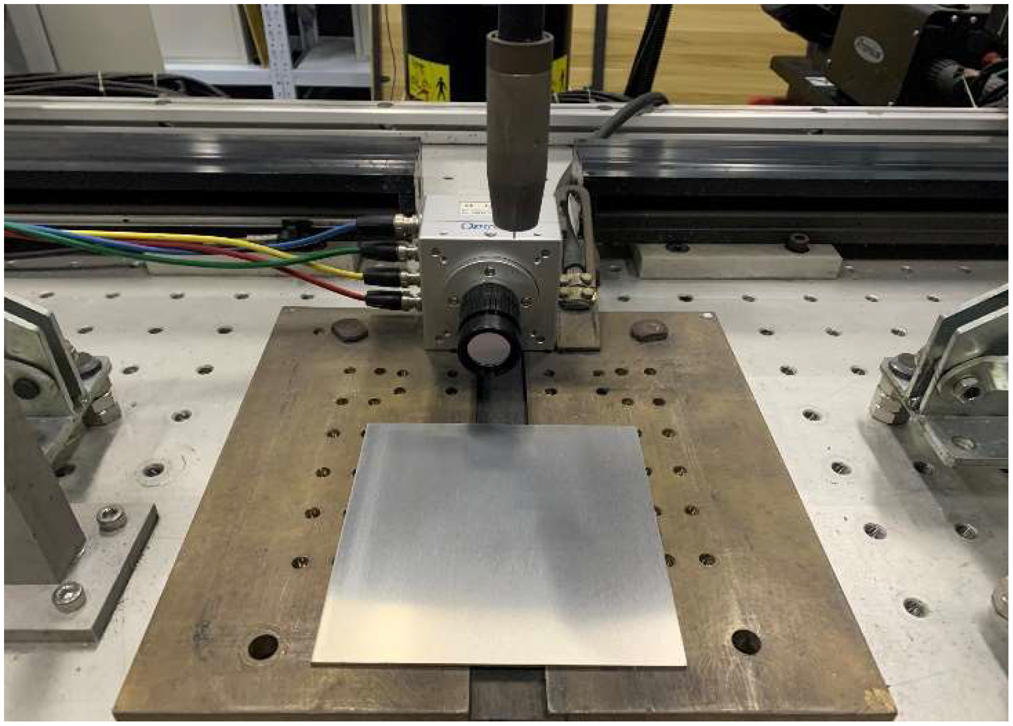
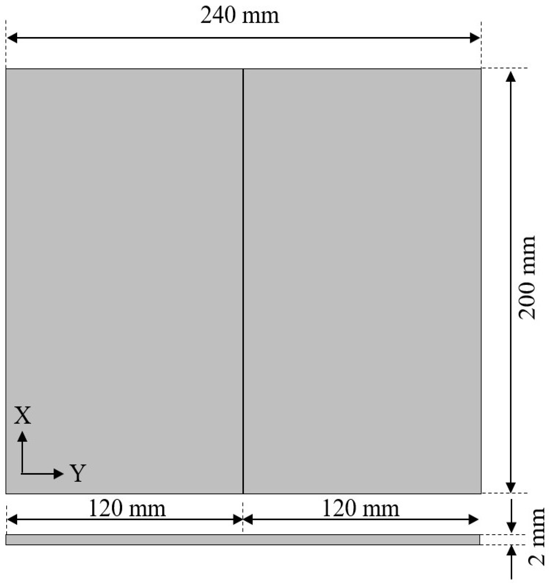
2. Materials and Methods

In order to analyze the theory of controlled driving and spreading of the molten pool, this research conducted corresponding verification experiments, the experiment analyzed the influence of the welding current on the controlled driving and spreading behavior of the molten pool under a single flow cycle, and the difference in the flow behavior of the molten pool. In order to analyze the difference between the controlled driving and spreading behavior of the molten pool, this experiment extracts specific nodes in the molten pool flow process and analyzes the static geometric characteristics of the molten pool under the specific nodes.
The molten pool flow experiment was performed on the CMT welding platform, and the 7075-aluminum alloy substrate was fixed above the platform. The molten pool is formed with ER4043 aluminum-silicon alloy welding wire, and high-purity argon gas protection treatment is carried out at the same time. Figure 1 and Figure 2 show the CMT molten pool flow experimental device, the KUKA robotic arm assists the CMT molten pool generation and controls the movement path and speed of the CMT welding gun. The wire feeding system adjusts the wire feeding speed. The initial distance between the end of the welding wire and the aluminum alloy substrate is fixed, and the welding torch feeds the droplets and forms a molten pool during the movement.
During the flow of the molten pool, a high-speed camera is used to record the flow direction and distance of the molten pool, the image capture rate of the high-speed camera is 4000 frames per second, and the images taken by the high-speed camera are collected within a fixed time. In order to ensure the stability of the molten pool flow process, under different welding currents, the movement speed of the same welding gun is controlled so that the length of the molten pool generated per unit time is consistent. Then collect the flow images of the molten pool under the corresponding welding current, and analyze the flow characteristics of the molten pool.
The moving speed of the welding gun is set to 0.48 m/min, and the initial welding current is set to 80 A, in this state, the wire feed speed is approximately 4.2 m/min. Then increase the welding current, and control the same moving path and speed of the welding gun. Regardless of the difference in thermal expansion of the molten pool, the welding current represents the wire feed speed, and the wire feed speed represents the droplet transfer volume, the specific parameters are set, see Table 1. In order to reduce the influence of the arc radius on the flow process of the molten pool, the arc correction is a negative critical correction.

3. Analytical Model of Controlled Driving and Spreading

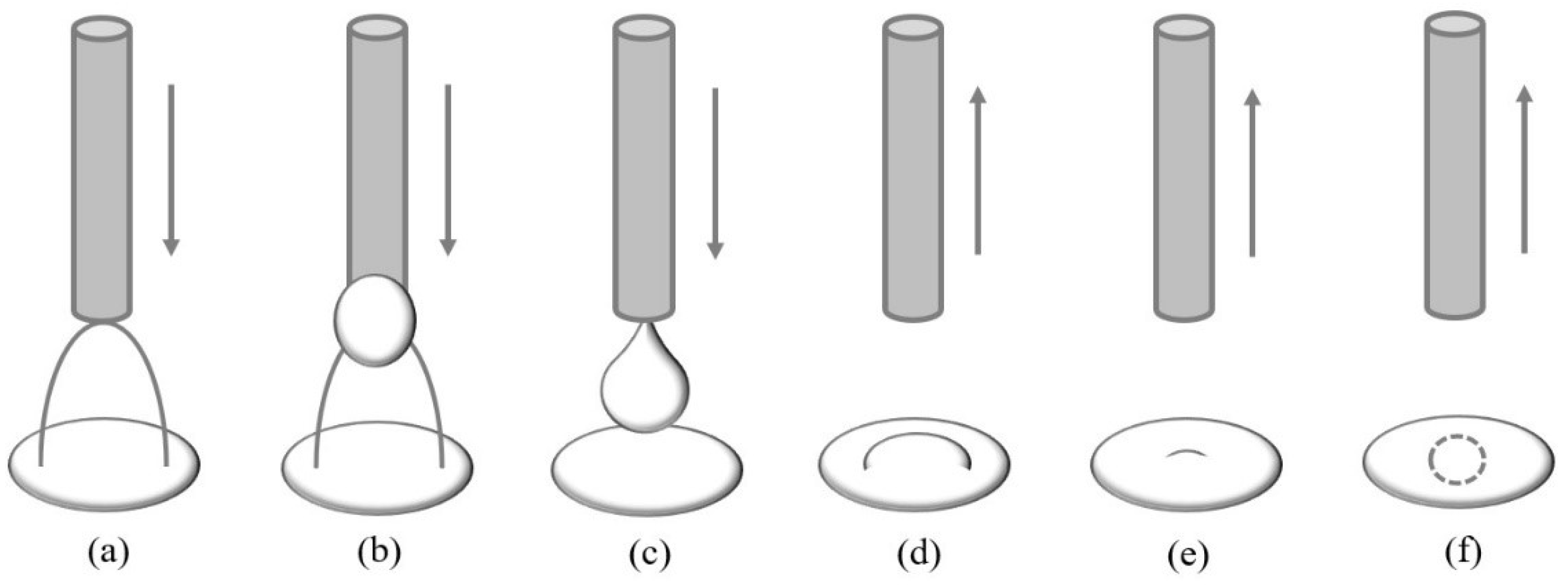
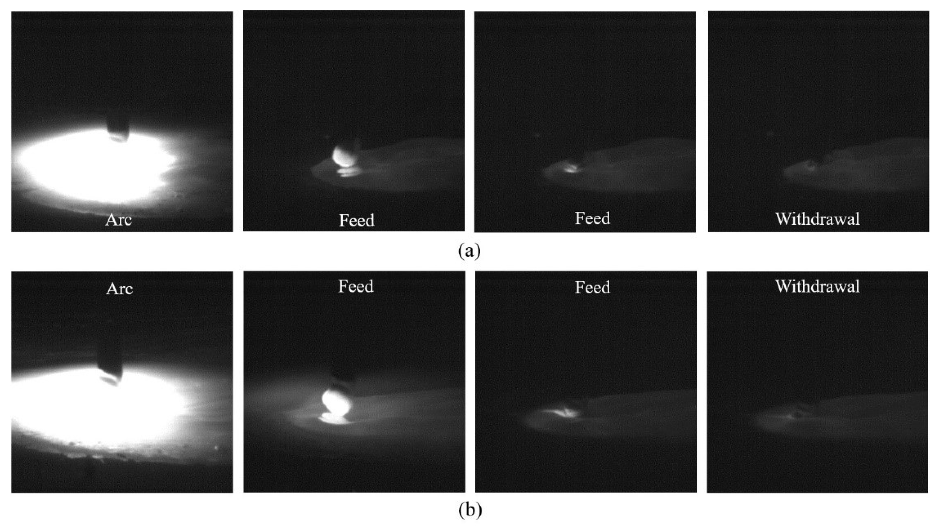
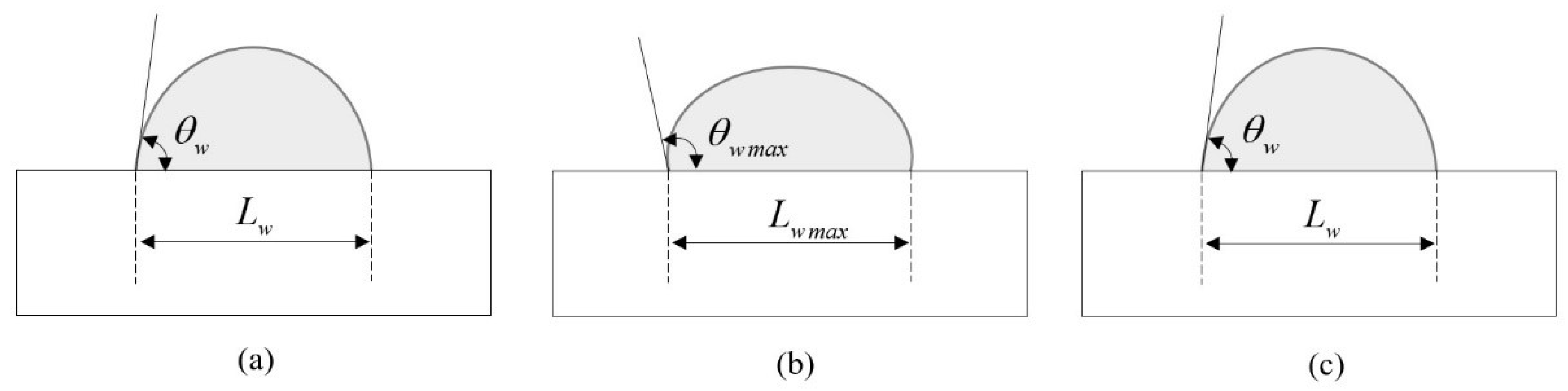
3.1. Controlled Driving and Spreading Process

The controlled driving and spreading behavior of the molten pool of CMT welding can be considered as a controlled cyclic process, as shown in Figure 3. It includes arc pressure drive, droplet impact and residual energy transfer. Before the droplet touches the molten pool, the molten pool is in the arc pressure driving stage. At the moment when the droplet touches the molten pool, the molten pool enters the droplet impact stage. After the droplet completely enters the molten pool, the molten pool enters the remaining energy of the molten droplet, the transfer phase. After a series of driving processes, the molten pool completes a single controlled driving and spreading cycle.
The controlled driving and spreading behavior of the molten pool is a process in which an electrode transfers energy, momentum and quality to the molten pool, as shown in Figure 4. Before the droplets reach the molten pool, the arc pressure acts on the surface of the molten pool to deform the surface of the molten pool. After the molten droplet reaches the molten pool, it transfers its own momentum and mass to the molten pool to increase the volume of the molten pool. After the molten droplet completely enters the molten pool, it transfers its own energy to the molten pool to further deform and drive the surface of the molten pool, and the molten pool flows around. The physical and material properties used to analyze the controlled driving and spreading behavior of the molten pool are shown in Table 2.

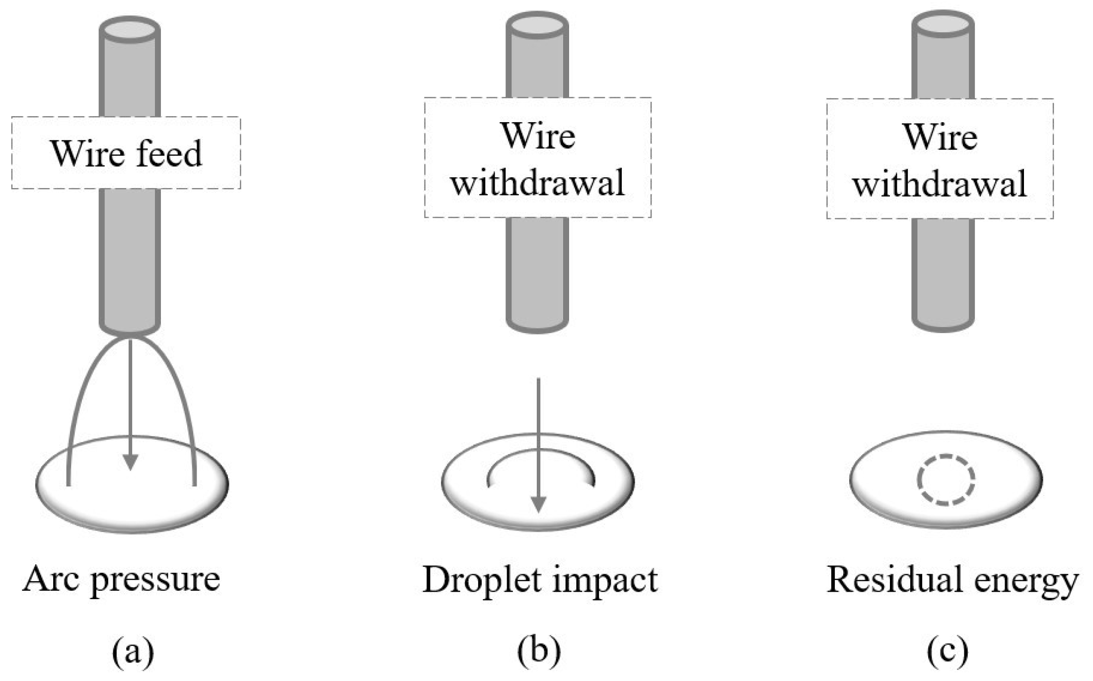
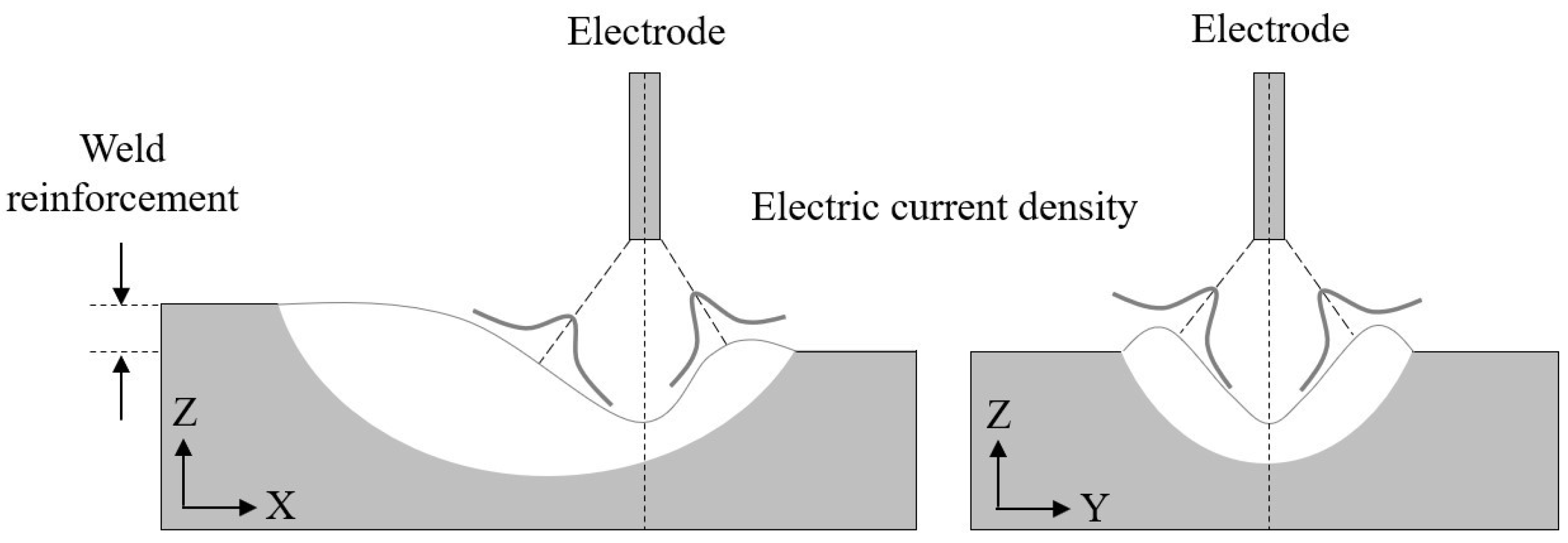
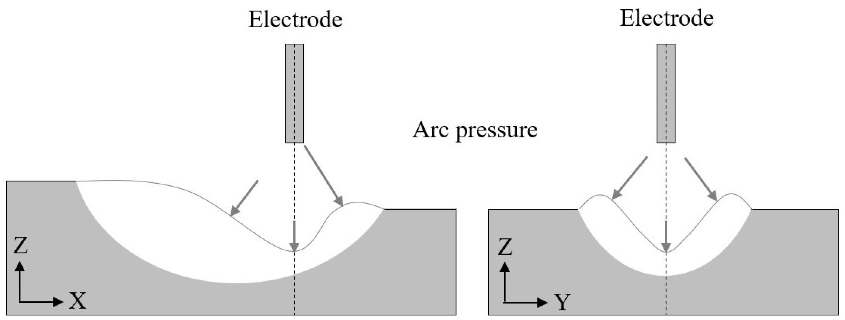
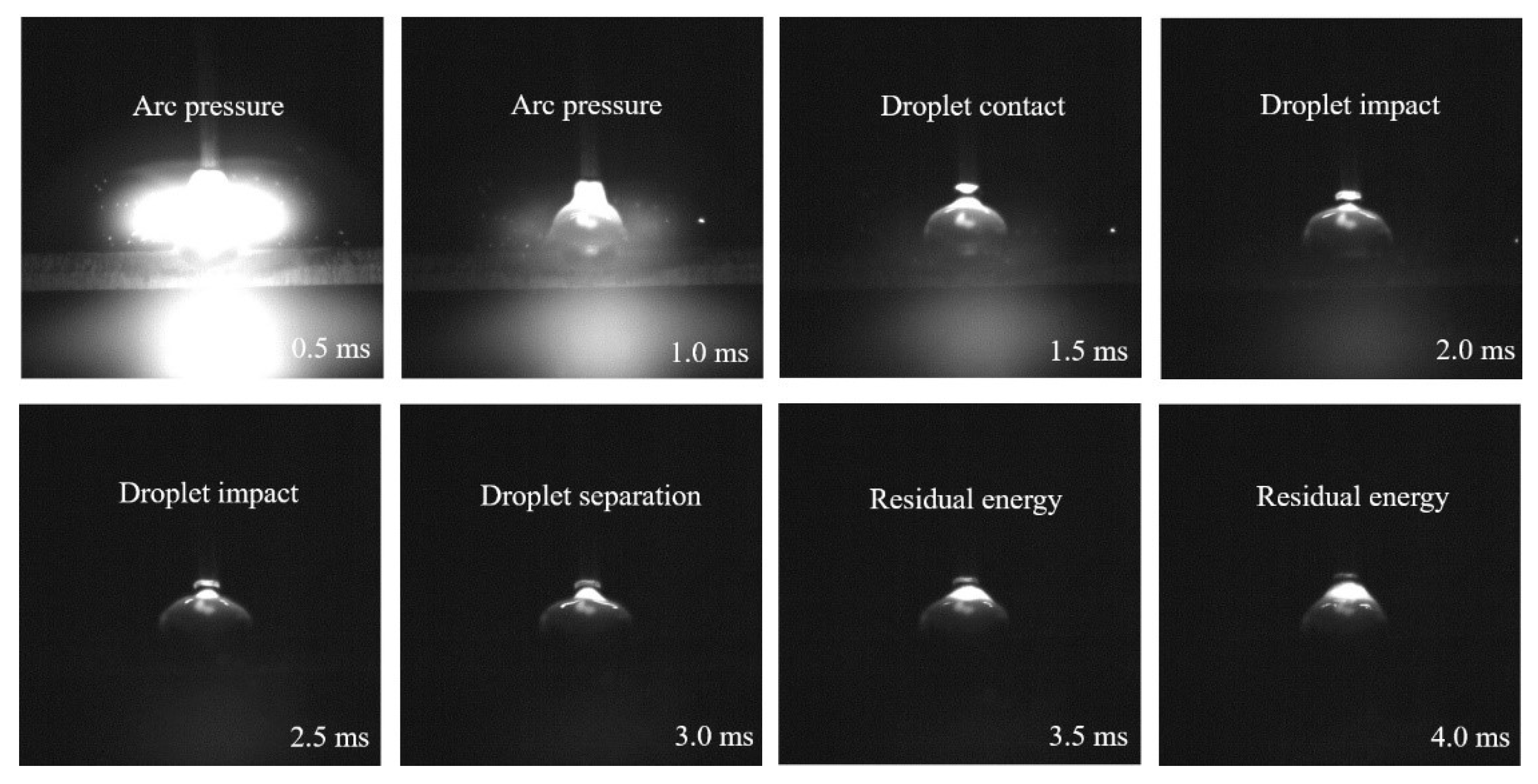
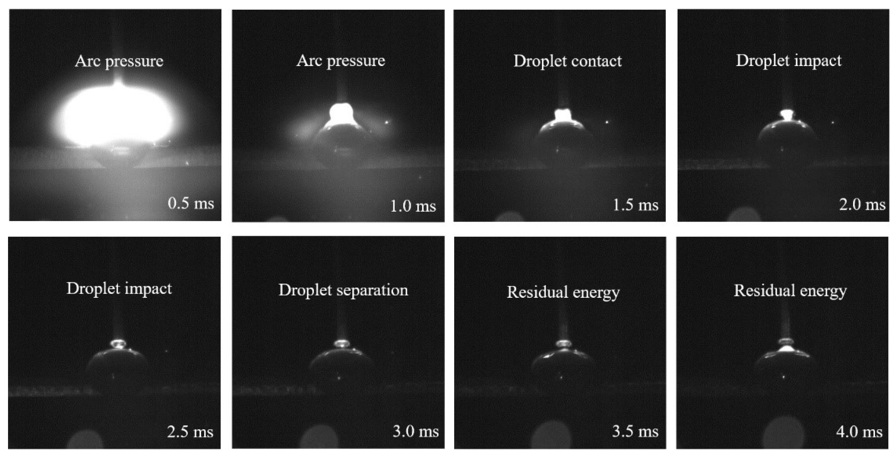
3.2. Arc Pressure Drive on the Surface of the Molten Pool
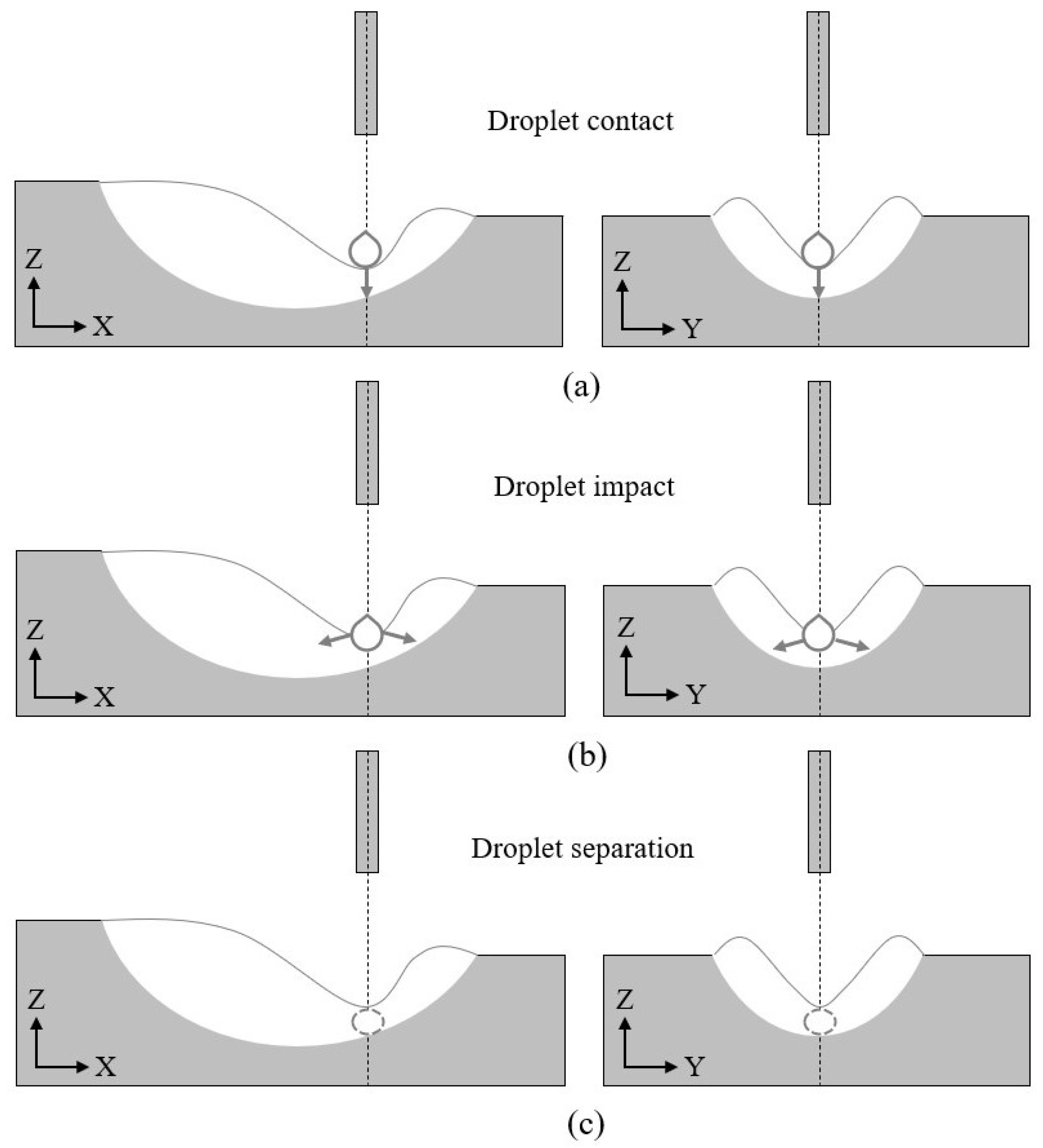
The driving action of the plasma fluid acting on the surface of the molten pool constitutes the arc pressure on the surface of the molten pool. It is generally believed that the plasma fluid acting on the surface of the molten pool drives the molten pool to flow in the direction of the plasma fluid velocity. For the molten pool of traditional TIG welding, because it is not affected by the impact of molten droplets, the surface of the molten pool is less dented and deformed. The arc pressure on the surface of the molten pool is large in the middle and small around it, and the arc pressure distribution basically conforms to the Gaussian distribution model. For the molten pool of CMT welding, due to the effect of the last controlled driving and spreading cycle, that is, the transfer of the remaining energy of the molten droplet, the concave deformation generated on the surface of the molten pool has not been completely eliminated. The surface of the molten pool is low in the middle and high around it, the keyhole is formed, which complicates the arc pressure distribution on the surface of the molten pool. Related studies believe that for the molten pool of MIG welding, the arc pressure on the surface of the molten pool is related to the welding current and the current density on the surface of the molten pool. Considering the similarity between CMT welding and the welding pool, the arc pressure of the CMT welding pool is also related to welding, the current is highly correlated with the current density on the surface of the molten pool, as shown in Figure 5.
The current density on the surface of the molten pool is highly correlated with the shape of the surface of the molten pool. In the tapered space between the electrode tip and the surface of the molten pool, conductive ions with uneven density are distributed. It is generally believed that conductive ions move from the end of the electrode to the surface of the molten pool along the shortest path. From the center of the molten pool to the periphery of the molten pool, the distance between the electrode end and the surface of the molten pool first decreases and then increases. In different directions, the radius of the plane with the smallest distance is different. In the direction of the wire movement, the plane radius is the smallest, and in the opposite direction of the wire movement, the plane radius is the largest. Therefore, it can be considered that the radius of the plane with the smallest distance from the electrode end to the surface of the molten pool basically conforms to the double ellipse distribution. In either direction, the distribution of conductive ions on the surface of the molten pool basically conforms to the Gaussian distribution. As the surface of the molten pool is low in the middle and high in the periphery, the conductive ions on the slope of the keyhole drive the molten pool to flow to the surrounding and bottom, as shown in Figure 6.
Therefore, assuming that in a certain direction, the conductive ions conform to the Gaussian distribution on the surface of the molten pool, and the current density distribution in a certain direction on the surface of the molten pool can be expressed as [23]:
J ( s ) = J max exp ( s 2 / 2 σ 2 )
Therefore, in any direction, the conductive ions on the surface of the molten pool conform to the Gaussian distribution, and the maximum current density is related to the current distribution parameters and the direction angle. The current density distribution in any direction on the surface of the molten pool can be expressed as:
J ( θ , s ) = J max ( θ ) exp ( s 2 / 2 σ 2 ( θ ) )
where s is the arc length of the origin curve, J m a x is the maximum current density, σ is the current distribution parameter, and θ is the angle between the plane directions.
Since most of the conductive ions move from the end of the electrode to the surface of the molten pool, only a small part of the conductive ions diffuse into the surrounding air environment, and the sum of the current on the surface of the molten pool is basically equal to the welding current, and there is an equation:
0 2 π l ( θ ) + l ( θ ) J ( θ , s ) ( s + l ( θ ) ) d s d θ = I
where l ( θ ) is the arc length of the maximum origin curve and I is the welding current.
Arc pressure is the pressure exerted by conductive ions on the surface of the molten pool. It is generally believed that the arc pressure is closely related to the welding current and current density distribution [24]. The arc pressure on the surface of the molten pool can be expressed as:
P = μ 0 I J 4 π
Therefore, the arc pressure on the surface of the molten pool is related to the position of the molten pool surface. At the front end of the molten pool surface, the arc pressure is larger, and at the rear end of the molten pool surface, the arc pressure is smaller. The arc pressure in any direction on the molten pool surface can be expressed for:
P ( θ , s ) = μ 0 I J max ( θ ) 4 π exp ( s 2 / 2 σ 2 ( θ ) )
Among them, according to the geometric relationship:
tan θ = y x
where μ 0 is the vacuum permeability, x is the horizontal axis distance of the plane, and y is the vertical axis distance of the plane.

3.3. Droplet Impact

The droplet is affected by electrode force and gravity during the falling process, and it accelerates to a specific speed to contact with the molten pool surface and cause an impact on the molten pool. The impact of the droplet on the molten pool causes a serious depression on the surface of the molten pool. At the moment when the droplet touches the surface of the molten pool, until the droplet completely enters the molten pool, the droplet transfers all its mass to the molten pool. On the one hand, it increases the height of the molten pool, after the weld is formed, it appears as a surplus height. On the one hand, the width of the molten pool is increased, which turns into a molten width after the weld is formed. In the process of the transfer of the molten droplet to the molten pool, the droplet momentum is the main factor that promotes the transfer of the liquid metal to the surroundings, as shown in Figure 7.
Welding current determines the momentum of the droplet. Studies have concluded that as the welding current increases, the transition frequency of the droplet increases, the impact velocity of the droplet increases, and the momentum of the droplet increases.
It is generally believed that the wire feed speed and the welding current are linearly related under the small welding current, and the welding wire feed speed and the welding current are nonlinearly related under the larger current condition [25]. The research believes that the wire feed speed can be expressed as:
d m d t = a I + b L 0 I 2
Without considering the droplet splash and pool evaporation, the wire feed speed is equal to the droplet feed quality per unit time, and the droplet feed quality per unit time is equal to the weld forming quality per unit time. Then there is an equation:
d m d t = 4 3 f d π r d 3 ρ = A w v w ρ
where a is the welding wire melting constant of the arc, b is the welding wire melting constant of Joule heat, L 0 is the wire extension length, f d is the droplet transition frequency, r d is the droplet radius, ρ is the droplet density, A w is the cross-sectional area of the weld, and v w is the welding speed.
The droplet transitions to the molten pool under the action of the feeding motion of the welding wire and gravity. As the distance between the welding wire and the substrate is fixed, the transition distance of the droplet is basically fixed.
The droplet transition distance can be expressed as:
0 t 1 v ( t ) d t = H
The droplet transition time can be expressed as:
t 1 = k 1 f d
where t 1 is the droplet transition time, H is the droplet transition height, and is the droplet transition constant.
From the moment the droplet comes into contact with the surface of the keyhole to the moment when the droplet and the surface of the keyhole separate, the high-speed moving droplet generates an impulse on the molten pool under the action of gravity, and at the same time performs fluid mechanical work on the molten pool [26].
The impulse of the molten droplet to the molten pool is equal to the change of the droplet momentum, and there is an equation:
t 1 t 2 ( F ( t ) m d g ) d t = m d ( v 1 v 2 )
The work done by the molten droplet on the molten pool is equal to the impact deformation energy of the molten pool, and there is an equation:
1 2 m v 1 2 1 2 m v 2 2 + 2 m d g r d = Δ E
where m d is the mass of the droplet, g is the acceleration of gravity, v 1 is the initial velocity of the impact, v 2 is the end velocity of the impact, and Δ E is the impact deformation energy of the molten pool.
Considering that the impact of the molten droplet on the molten pool is a continuous process, the molten droplet decelerates during the impact process. Considering that the molten droplet and the surface of the molten pool are in contact with each other, the spherical surface of the molten droplet has been greatly deformed, so the impact force of the molten droplet can be expressed for:
P = f d m d ( v 1 v 2 ) + k 2 m d g k 2 π r d 2
Among them, according to the sphere mass calculation formula:
m d = 4 3 π r d 3 ρ
where k 2 is the droplet transition constant.

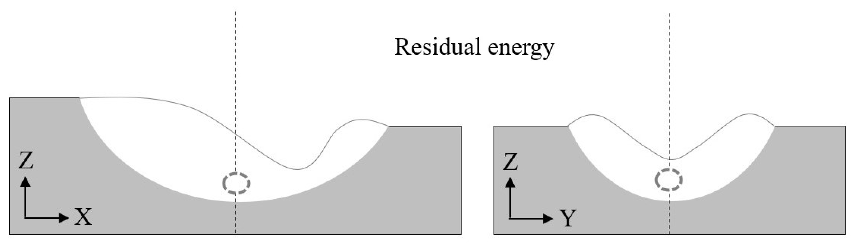
3.4. Residual Energy Transfer

The impact process of the molten droplet on the molten pool consumes part of the energy of the molten droplet. After the molten droplet completely enters the molten pool, the remaining part of the energy makes the molten droplet move into the molten pool. Due to the high flow velocity in the middle of the molten pool, the surrounding flow rate is low, the liquid metal has an intermediate depression phenomenon, and promotes further depression and deformation on the surface of the molten pool. Generally, it can be considered that the momentum of the molten droplet decreases sharply when the molten droplet moves to the inside of the molten pool. The next time the molten pool is driven and controlled before the spreading cycle, that is, at the stage of arc pressure on the surface of the molten pool, the momentum of the molten droplet was reduced to a negligible level, as shown in Figure 8.
Welding current determines the remaining energy of the molten droplet. Studies have concluded that as the welding current increases, the momentum of the molten droplet increases. Since the droplet quality and impact speed determine the remaining energy of the droplet, in the process of the droplet impacting the molten pool, the larger the droplet mass, the greater the energy consumption of the droplet, and the greater the impact velocity of the droplet, the greater the energy consumption of the droplet [27].
From the time when the molten droplet completely enters the molten pool to the stop of the relative movement between the molten droplet and the molten pool, the low-speed moving droplet performs fluid mechanical work on the molten pool under the action of gravity [28].
The work done by the remaining energy of the molten droplet on the molten pool is equal to the remaining impact deformation energy of the molten pool, and there is an equation:
0 h ( F ( s ) m d g ) d s = 1 2 m v 2 2
Then there is the equation:
E = 1 2 m v 2 2 + m d g h
where h is the remaining impact distance and E is the remaining impact deformation energy of the molten pool.

3.5. Theoretical Model of Controlled Drive and Spreading

Therefore, the controlled driving and spreading behavior of the CMT molten pool is a cyclic process, which includes arc pressure driving on the molten pool surface, droplet impact and residual energy transfer. Before the droplets reach the molten pool, the arc pressure acts on the surface of the molten pool, and the surface of the molten pool is deformed. After the molten droplet reaches the molten pool, it transmits its own mass and momentum to the molten pool to increase the depression of the molten pool [29]. After the molten droplet completely enters the molten pool, it transfers its own remaining energy to the molten pool, and the surface of the molten pool is further deformed and driven the molten pool flows around, as shown in Figure 9.
It is generally believed that the sum of the forces on the surface of the keyhole causes the change of the surface of the keyhole, and the surface shape equation of the molten pool can be expressed as [30]:
P ( θ , s ) + P d + P E ρ g z ( x , y ) = γ ( 1 / R 1 + 1 / R 2 )
Among them, according to the calculation formula of the space surface curvature:
1 R 1 + 1 R 2 = ( F ( x , y , z ) / | F ( x , y , z ) | )
where P ( θ , s ) is the arc pressure, P d is the droplet impact force, P E is the remaining droplet impact force, γ is the surface tension coefficient, R 1 is the transverse radius of curvature, and R 2 is the longitudinal radius of curvature.
Since the sum of the forces on the surface of the molten pool is mainly concentrated in the keyhole area, and the surface of the keyhole is continuous and guidable, the keyhole shape equation on the surface of the molten pool can be expressed as:
z ( x , y ) = { a k 1 x 2 + b k y 2 h k ( x 0 ) a k 2 x 2 + b k y 2 h k ( x 0 )
Since the area of the top section of the keyhole is only affected by the arc characteristics, and the keyhole curve is continuous and guidable, the keyhole shape equation can be expressed in a single direction as:
z ( x ) = { a k 1 x 2 h k , h k = a k 1 r 11 2 h w ( y = 0 , x 0 ) a k 2 x 2 h k , h k = a k 2 r 12 2 h w ( y = 0 , x 0 )
z ( y ) = b k y 2 h k , h k = b k r 2 2 h w ( x = 0 )
Therefore, under a fixed arc characteristic, the sum of the forces on the surface of the molten pool can affect the depth and width of the keyhole, and the height of the top section of the keyhole is basically unaffected, that is, the height of the molten pool surface is basically the same.
It is generally believed that when the molten pool flows into the solidification process of the molten pool, the molten pool and the substrate are in slow and continuous contact, and the contact angle of the molten pool is small. When the molten pool is solidified and the weld is formed, the surface of the weld is continuous, and the cross-sectional curve of the weld is continuous, basically conforming to the quadratic function distribution, therefore, the weld cross-section curve can be expressed as:
z = a w y 2 + h w
where a w is the constant of the section curve and h w is the weld reinforcement.
Then there is the equation:
L w / 2 + L w / 2 ( a w y 2 + h w ) d y = A w
d z d y | z = 0 = tan θ w
Therefore, the weld width can be expressed as:
L w = 6 ( a I + b L 0 I 2 ) h w 2 v w 2 ρ 2 + 18 v w ρ ( a I + b L 0 I 2 ) h w v w ρ
The weld contact angle can be expressed as:
θ w = arctan 2 h w h w 2 v w ρ + 18 v w ρ ( a I + b L 0 I 2 ) 2 h w 2 v w ρ 3 ( a I + b L 0 I 2 )

4. Analysis and Discussion

4.1. Molten Pool Transition Method

During the controlled driving cycle of the CMT molten pool, the transition form of the molten droplet is an important factor in determining the melt flow behavior. Under a small welding current, the transition form of the molten droplet is a droplet transition. At a moderate welding current, the transition form of droplets is droplet transition, and under larger welding current, the transition form of droplets is jet transition. Studies have shown that the form of droplet transition affects the flow form of the molten pool to a large extent. The droplet transition can bring a lot of heat to the root of the molten pool, and the droplet transition can bring more heat to the tail of the molten pool. In order to reduce the influence of heat input on the flow process of the molten pool and effectively analyze the influence of the molten droplet on the controlled cycle driving process of the molten pool, the experiment adopts a droplet transition form to analyze the flow process of the molten pool. The cross-sectional dimensions of the molten pool are shown in Figure 10.

4.2. The Controlled Driving Process of the Molten Pool

In a single CMT molten pool-controlled driving cycle, the arc pressure, droplet impact and residual energy transfer on the molten pool surface continuously transfer the molten pool laterally. In the arc pressure driving phase, the molten pool is driven by force for 1 ms, the molten pool is transferred in a smaller range. In the droplet impact phase, the force-driven time of the molten pool is 2 ms, and the molten pool spreads over a large area. In the remaining energy stage, the molten pool is driven by force for 1 ms, and the molten pool continues to transfer to the surroundings, and then reflows. Under the welding current of 80 A, the controlled driving cycle of the molten pool is shown in Figure 11. Under the welding current of 100 A, the controlled driving cycle of the molten pool is shown in Figure 12.
In a single CMT molten pool-controlled driving cycle, the molten pool is sequentially subjected to arc pressure, droplet impact and residual energy. During the arc pressure driving stage, the recessed area of the molten pool under the arc expands, the slope area affected by the arc spreads to the surroundings, and the molten pool flows to the surroundings. In the droplet impact phase, the depression area of the molten pool continues to expand, the arc-acting slope area continues to spread around, and the molten pool continues to flow around. In the remaining energy stage, the surface of the molten pool first produces a keyhole depression phenomenon, and then the depression phenomenon is obtained recovery. Under different welding currents, the degree of keyhole formation and recovery on the surface of the molten pool are different, the reflow speed and reflow distance of the molten pool are different, the height and width of the molten pool are different. Under the welding current of 80 A, the change trend of the molten pool is shown in Figure 13, its maximum melting width can reach 6.15 mm, and its maximum contact angle can reach 1.65. Under the welding current of 100 A, the change trend of the molten pool is shown in Figure 14, its maximum melting width can reach 7.65 mm, and its maximum contact angle can reach 1.56.

4.3. Controlled Driving and Spreading Process

For different welding currents, the spreading process of the molten pool in the three stages is different. When the welding current is set to 80 A, the spreading range of the molten pool is smaller and the width of the molten pool is narrow. The spreading process of the molten pool is mainly concentrated in the first and second stages, the experimental melting width is 5.4 mm, the experimental contact angle is 1.0725, the predicted melting width is 5.9648 mm, and the predicted contact angle is 1.25. When the welding current is set to 90 A, the spreading range of the molten pool increases and the width of the molten pool increases. Similarly, the spreading process of the molten pool is mainly concentrated in the first and second stages, the experimental melting width is 6.6 mm, the experimental contact angle is 1.0334, the predicted melting width is 6.5640 mm, and the predicted contact angle is 1.05. When the welding current is set to 100 A, the spreading range of the molten pool continues to increase, and the width of the molten pool continues to increase. The spreading process of the molten pool is mainly concentrated in the second stage, the experimental melting width is 7.3 mm, the experimental contact angle is 0.9773, the predicted melting width is 7.1650 mm, and the predicted contact angle is 1.01. When the welding current is set to 110 A, under the influence of the surface tension of the molten pool, the spread of the molten pool has reached the limit state, the spreading range of the molten pool is basically unchanged, the height of the molten pool is basically unchanged, and the width of the molten pool is basically unchanged. Similarly, the spreading process of the molten pool is mainly concentrated in the second stage, the experimental melting width is 7.6 mm, the experimental contact angle is 0.9593, the predicted melting width is 7.7674 mm, and the predicted contact angle is 0.99, the spreading characteristics are shown in Figure 15, and the spreading width and contact angle of the molten pool are shown in Figure 16 and Figure 17.

5. Conclusions

In this study, based on the controlled cycle of cold metal transition, a theoretical model of the controlled driving and spreading of the cold metal transition bath was established, and the mechanism of the single controlled driving and spreading of the molten bath was deduced.
The arc pressure, droplet impact and residual energy on the surface of the molten pool have a decisive influence on the flow process of the molten pool. The sum of the forces on the surface of the molten pool can determine the surface shape of the keyhole and change the overall size of the molten pool.
The welding current has a decisive effect on the flow behavior of the molten pool. Increasing the welding current cannot change the remaining height of the molten pool, but it can increase the width of the molten pool and reduce the contact angle of the molten pool. The welding current is increased from 80 A to 100 A, the maximum melting width is increased from 6.15 mm to 7.65 mm, and the maximum contact angle is reduced from 1.65 to 1.56.
The theoretical model of molten pool spreading predicts the width and contact angle of the molten pool, which is consistent with the experimental results, when the welding current is between 90 A and 110 A, the predicted results are highly consistent with the experimental results. The forming process and geometry of the weld can be predicted based on the molten pool spreading model.

Author Contributions

Methodology, A.Z. and Y.X.; software, A.Z.; validation, A.Z.; formal analysis, A.Z.; investigation, A.Z.; resources, A.Z.; data curation, A.Z.; writing—original draft preparation, A.Z.; writing—review and editing, A.Z.; visualization, A.Z.; supervision, Y.X. and X.Z.; project administration, Y.X. and F.Y.; funding acquisition, Y.X. and J.C. All authors have read and agreed to the published version of the manuscript.

Funding

This research received no external funding.

Institutional Review Board Statement

Not applicable.

Informed Consent Statement

Not applicable.

Data Availability Statement

The data used to support the findings of this study are available from the corresponding author upon request.

Acknowledgments

This work was partially supported by the Natural Science Foundation of Shanghai (Grant No. 20ZR1422600) and the Open Project of Shanghai Key Laboratory of Digital Manufacture for Thin-walled Structures (Grant No. 2019–002).

Conflicts of Interest

The authors declare that they have no conflict of interest.

References

  1. Wu, F.; Falch, K.; Guo, D.; English, P.; Drakopoulos, M.; Mirihanage, W. Time evolved force domination in arc weld pools. Mater. Des. 2020, 190, 108534. [Google Scholar] [CrossRef]
  2. Shi, Y.; Li, C.; Du, L.; Gu, Y.; Zhu, M. Frequency characteristics of weld pool oscillation in pulsed gas tungsten arc welding. J. Manuf. Processes 2016, 24, 145–151. [Google Scholar]
  3. Meng, X.; Qin, G.; Zou, Z. Characterization of molten pool behavior and humping formation tendency in high-speed gas tungsten arc welding. Int. J. Heat Mass Transf. 2018, 117, 508–516. [Google Scholar] [CrossRef]
  4. Cai, J.; Feng, Y.; Zhou, J.; Li, Y.; Zhang, X.; Wu, C. Numerical analysis of weld pool behaviors in plasma arc welding with the lattice Boltzmann method. Int. J. Therm. Sci. 2018, 124, 447–458. [Google Scholar] [CrossRef]
  5. Huang, J.; Pan, W.; Chen, J.; Shao, Y.; Yang, M.; Zhang, Y. The transient behaviours of free surface in a fully penetrated weld pool in gas tungsten arc welding. J. Manuf. Processes 2018, 36, 405–416. [Google Scholar] [CrossRef]
  6. Liu, X.; Wu, C.; Jia, C.; Zhang, G. Visual sensing of the weld pool geometry from the topside view in keyhole plasma arc welding. J. Manuf. Processes 2017, 26, 74–83. [Google Scholar] [CrossRef]
  7. Nguyen, A.; Tashiro, S.; Ngo, M.; Bui, H.; Tanaka, M. Effect of the eddies formed inside a weld pool on welding defects during plasma keyhole arc welding. J. Manuf. Processes 2020, 59, 649–657. [Google Scholar] [CrossRef]
  8. Li, Y.; Tian, S.; Wu, C.; Tanaka, M. Experimental sensing of molten flow velocity, weld pool and keyhole geometries in ultrasonic-assisted plasma arc welding. J. Manuf. Processes 2021, 64, 1412–1419. [Google Scholar] [CrossRef]
  9. Wu, D.; Tashiro, S.; Hua, X.; Tanaka, M. Analysis of the energy propagation in the keyhole plasma arc welding using a novel fully coupled plasma arc-keyhole-weld pool model. Int. J. Heat Mass Transf. 2019, 141, 604–614. [Google Scholar] [CrossRef]
  10. Ning, J.; Zhang, L.; Zhang, L.; Long, J.; Yin, X.; Zhang, J.; Na, S. Effects of power modulation on behaviours of molten pool and keyhole during laser–arc hybrid welding of pure copper. Mater. Des. 2020, 194, 108829. [Google Scholar] [CrossRef]
  11. Wu, D.; Nguyen, A.; Tashiro, S.; Hua, X.; Tanaka, M. Elucidation of the weld pool convection and keyhole formation mechanism in the keyhole plasma arc welding. Int. J. Heat Mass Transf. 2019, 131, 920–931. [Google Scholar] [CrossRef]
  12. Yang, M.; Liu, H.; Qi, B. The surface depression and temperatures in molten pool with pulsed arc welding. J. Manuf. Processes 2019, 37, 130–138. [Google Scholar] [CrossRef]
  13. Meng, X.; Qin, G.; Zou, Z. Sensitivity of driving forces on molten pool behavior and defect formation in high-speed gas tungsten arc welding. Int. J. Heat Mass Transf. 2017, 107, 1119–1128. [Google Scholar] [CrossRef]
  14. Meng, X.; Qin, G. A theoretical study of molten pool behavior and humping formation in full penetration high-speed gas tungsten arc welding. Int. J. Heat Mass Transf. 2019, 132, 143–153. [Google Scholar] [CrossRef]
  15. Wang, D.; Lu, H. Numerical analysis of internal flow of molten pool in pulsed gas tungsten arc welding using a fully coupled model with free surface. Int. J. Heat Mass Transf. 2021, 165, 120572. [Google Scholar] [CrossRef]
  16. Chen, C.; Wei, X.; Zhao, Y.; Yan, K.; Jia, Z.; He, Y. Effects of helium gas flow rate on arc shape, molten pool behavior and penetration in aluminum alloy DCEN TIG welding. J. Mater. Process. Technol. 2018, 255, 696–702. [Google Scholar] [CrossRef]
  17. Eda, S.; Ogino, Y.; Asai, S.; Hirata, Y. Numerical study of the influence of gap between plates on weld pool formation in arc spot welding process. Weld. World 2018, 62, 1021–1030. [Google Scholar] [CrossRef]
  18. Zong, R.; Chen, J.; Wu, C. A comparison of TIG-MIG hybrid welding with conventional MIG welding in the behaviors of arc, droplet and weld pool. J. Mater. Process. Technol. 2019, 270, 345–355. [Google Scholar] [CrossRef]
  19. Murphy, A.; Thomas, D. Prediction of arc, weld pool and weld properties with a desktop computer model of metal–inert-gas welding. Weld. World 2017, 61, 623–633. [Google Scholar] [CrossRef]
  20. Ikram, A.; Chung, H. Numerical simulation of arc, metal transfer and its impingement on weld pool in variable polarity gas metal arc welding. J. Manuf. Processes 2021, 64, 1529–1543. [Google Scholar] [CrossRef]
  21. Cho, W.; Na, S. Impact of driving forces on molten pool in gas metal arc welding. Weld. World 2021, 65, 1735–1747. [Google Scholar] [CrossRef]
  22. Komen, H.; Shigeta, M.; Tanaka, M. Numerical simulation of molten metal droplet transfer and weld pool convection during gas metal arc welding using incompressible smoothed particle hydrodynamics method. Int. J. Heat Mass Transf. 2018, 121, 978–985. [Google Scholar] [CrossRef]
  23. Wang, Y.; Tsai, H. Effect of surface active elements on weld pool fluid flow and weld penetration in gas metal arc welding. Metall. Mater. Trans. B 2001, 32, 501–515. [Google Scholar] [CrossRef]
  24. Kim, C.; Zhang, W.; Debroy, T. Modeling of temperature field and solidified surface profile during gas metal arc fillet welding. J. Appl. Phys. 2003, 94, 2667–2669. [Google Scholar] [CrossRef] [Green Version]
  25. Esser, W.; Walter, R. Heat transfer and penetration mechanisms with GMA and plasma-GMA welding. Weld. J. 1981, 60, 37–42. [Google Scholar]
  26. Ushio, M.; Wu, C. Mathematical modeling of three-dimensional heat and fluid flow in a moving gas metal arc weld pool. Metall. Mater. Trans. B 1997, 28, 509–516. [Google Scholar] [CrossRef]
  27. Tsao, K.; Wu, C. Fluid flow and heat transfer in GMA weld pools. Weld. J. 1988, 67, 70–75. [Google Scholar]
  28. Kim, Y.; Eagar, T. Analysis of metal transfer in gas metal arc welding. Weld. J. 1993, 72, 269–277. [Google Scholar]
  29. Ghosh, K. Chemical Engineering. In ASM Handbook of Engineering Mathematics; ASM: Geauga County, OH, USA, 1983; Volume 90, p. 75. [Google Scholar]
  30. Ketter, R.; Pravel, S. Modern Methods of Engineering Computation; McGraw-Hill Book Company: New York, NY, USA, 1971; Volume 66, p. 660. [Google Scholar]
Figure 1. CMT molten pool flow experiment device.
Energies 15 01575 g001
Figure 2. CMT molten pool flow substrate size.
Energies 15 01575 g002
Figure 3. Simplified controlled cycle process of the molten pool (a,b) Arc pressure; (ce) Droplet impact; (f) Residual energy transfer.
Energies 15 01575 g003
Figure 4. Simplified controlled driving and spreading process of the molten pool. (a) Wire feed: arc pressure; (b) Wire withdrawal: droplet impact; (c) Wire withdrawal: residual energy transfer.
Energies 15 01575 g004
Figure 5. Current density distribution on the surface of the molten pool.
Energies 15 01575 g005
Figure 6. Arc pressure distribution on the surface of the molten pool.
Energies 15 01575 g006
Figure 7. Process of droplet impact (a) the moment of droplet contact; (b) the moment of droplet impact; (c) the moment of droplet separation.
Energies 15 01575 g007
Figure 8. Residual energy transfer.
Energies 15 01575 g008
Figure 9. Deformation process of the surface depression of the molten pool under different welding currents: (a) Pulse current is 80 A; (b) Pulse current is 100 A.
Energies 15 01575 g009
Figure 10. The width and contact angle of molten pool section.(a) Early stage of single cycle; (b) Middle stage of single cycle; (c) Late stage of single cycle.
Energies 15 01575 g010
Figure 11. Controlled driving cycle of the molten pool with a welding current of 80 A.
Energies 15 01575 g011
Figure 12. Controlled driving cycle of the molten pool with a welding current of 100 A.
Energies 15 01575 g012
Figure 13. The change process of the weld pool size at a welding current of 80 A.
Energies 15 01575 g013
Figure 14. The change process of the weld pool size at a welding current of 100 A.
Energies 15 01575 g014
Figure 15. The spreading effect of the molten pool under different currents.
Energies 15 01575 g015
Figure 16. The changing trend of the spreading width of the molten pool.
Energies 15 01575 g016
Figure 17. The change trend of the spreading contact angle of the molten pool.
Energies 15 01575 g017
Table 1. Experimental parameter settings.
Test CodeWelding CurrentWelding Speed
180 A0.48 m/min
285 A0.48 m/min
390 A0.48 m/min
495 A0.48 m/min
5100 A0.48 m/min
6105 A0.48 m/min
7110 A0.48 m/min
8115 A0.48 m/min
Table 2. Physical and material properties used for analysis.
PropertiesSymbolValue
Density ρ 2.7 × 10⁶ g/m3
Arc heating parameter a 7.5 × 10⁻⁵ g/As
Joule heating parameter b 2.5 × 10⁻³ g/mA2s
Extension length L 0 1.2 × 10⁻² m
Transfer distance H 1.0 × 10⁻² m
Transfer time constant k 1 0.4
Impact time constant k 2 0.08
Surface tension γ 1.2 N/m
Publisher’s Note: MDPI stays neutral with regard to jurisdictional claims in published maps and institutional affiliations.

