
How to Reduce the Design of Disc-Shaped Heat Exchangers to a Zero-Degrees-of-Freedom Task †


Department of Mechanical and Aerospace Engineering, University of Roma “La Sapienza”, Via Eudossiana 18, 00184 Rome, Italy
†
This article was adapted from a paper presented at the 34th International Conference on Efficiency, Cost, Optimization, Simulation and Environmental Impact of Energy Systems (ECOS 2021), Taormina, Italy, 27 June–2 July 2021, paper #281.
†
This article was adapted from a paper presented at the 34th International Conference on Efficiency, Cost,
Optimization, Simulation and Environmental Impact of Energy Systems (ECOS 2021), Taormina, Italy,
27 June–2 July 2021, paper #281.
Energies 2022, 15(3), 1250; https://doi.org/10.3390/en15031250
Submission received: 18 September 2021
/
Revised: 22 December 2021
/
Accepted: 19 January 2022
/
Published: 8 February 2022
(This article belongs to the Special Issue Selected Papers from ECOS 2021—34th International Conference on Efficiency, Cost, Optimization, Simulation, and Environmental Impact of Energy Systems)
Abstract
:The continuous quest for improving the performance of heat exchangers, together with ever more stringent volume and weight constraints, especially in enclosed applications like internal combustion engines and electronic devices, has stimulated the search for compact, high-performance units. One of the shapes that has emerged from a vast body of research is the disc-shaped heat exchanger, in which the fluid to be heated/cooled flows through radial—often bifurcated—channels carved inside a metallic disc. The disc in turn exchanges thermal energy with the hot/cold source (the environment or another body). Several studies have been devoted to the identification of an “optimal shape” of the channels: most of them are based on the extremization of some global property of the device, like its monetary or resource cost, its efficiency, the outlet temperature of one of the fluids, the total irreversibility of the process, etc. The present paper demonstrates that-for all engineering purposes there is only one correct design procedure for such a heat exchanger, and that if a few basic rules of engineering common sense are adopted, this procedure depends solely on the technical specifications (type of operation, thermal load, materials, surface quality): the design in fact reduces to a zero-degree of freedom problem. The procedure is described in detail, and it is shown that a proper application of the constraints completely identifies the shape, size and similarity indices of both the disc and the internal channels. The goal of this study is to demonstrate that-in this, as in many similar cases-a straightforward application of prime principles and of diligent engineering rules, may generate “optimal” designs: these principles guarantee a sort of “embedded optimality”.
1. Introduction
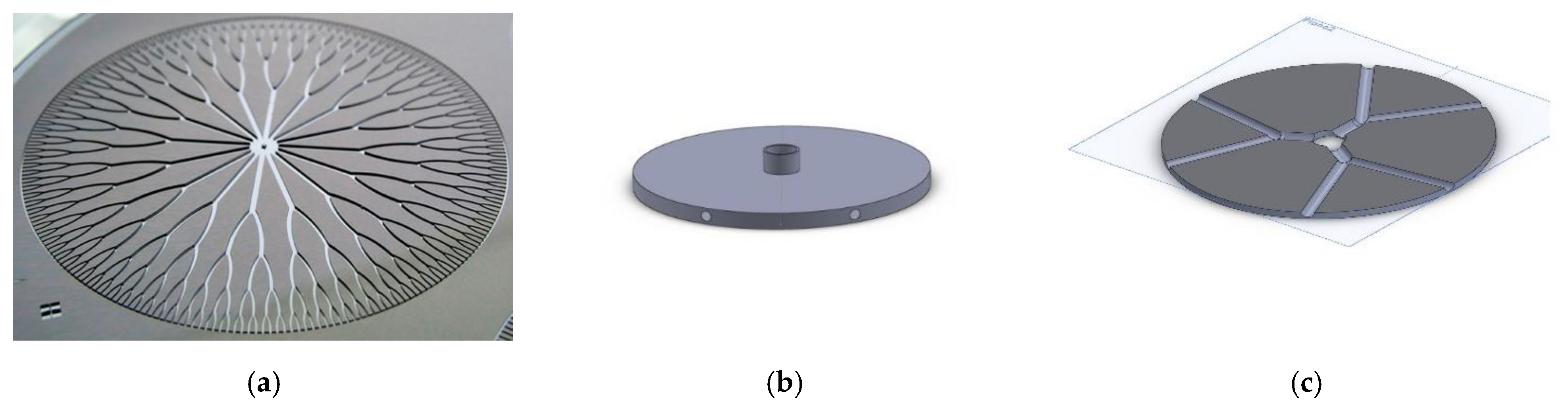
The general structure of a disc-shaped heat exchanger (DSHE) element is shown in Figure 1. A disc with an external radius “Rzb” is internally cooled or heated by a series of internal channels that originate from an axial inlet O and develop radially outwards in a branching fashion; the working fluid may be ejected radially or be collected by a toroidal manifold placed on the external periphery of the disc. The channels may have different cross-sections, hydraulic diameters and lengths. For the sake of simplicity, in this paper the internal channels are assumed to have a circular section and to perform the function of cooling the disc material.
One of the first problems designers must solve is the identification of the—rarely unique—set of lengths Lj and diameters dj of the channels. Another design issue is how to determine whether a larger number of branchings (i.e., a “more dendritic” structure) leads to a performance improvement, and how to quantify the correlation between the number of branches and the DSHE performance. Finally, one must investigate whether the branching angles βj (that represent so to say the “footprint” of the branchings) have an influence on the overall heat exchange characteristics.
In heat exchanger textbooks and manuals the problem is usually formulated in terms of “heat gain” of the working fluid versus “pressure drop” along the channels, the goal being that of maximizing the former while minimizing the latter [1]. A somewhat more sophisticated approach is that of calculating both the thermal entropy generation rate (due to the local temperature gradients in the fluid and in the disc) and its viscous counterpart (due to friction) and minimizing their sum; since the former is proportional to the HE efficiency and the latter to the pumping power, a global optimum is reached that balances benefits and costs of the energy exchange [2,3,4,5,6,7]. More recently, approaches have been proposed that introduce material costs considerations, either by applying thermo-economic principles or exergy analysis [8].
All of these studies lead to the definition of one or more similarity parameters directly linked to performance indicators: these “shape parameters” are the ratio of the diameters of successive branches, δj = dj+1/dj; that of successive lengths, λj = Lj+1/Lj and that of the diameter of the first branch to the disc radius, δ0 = d0/Rzb. Quite obviously, the more branches are etched inside of the disc, the more uniform the heat extraction from the solid material, and the better the performance: thus, both the initial number of “sectors” in which the disc is subdivided (first branches, z0) and the total number of peripheral discharge points, zb = 2nz0 (n = 0, n being the number of branching levels) have an influence on the performance of the device.
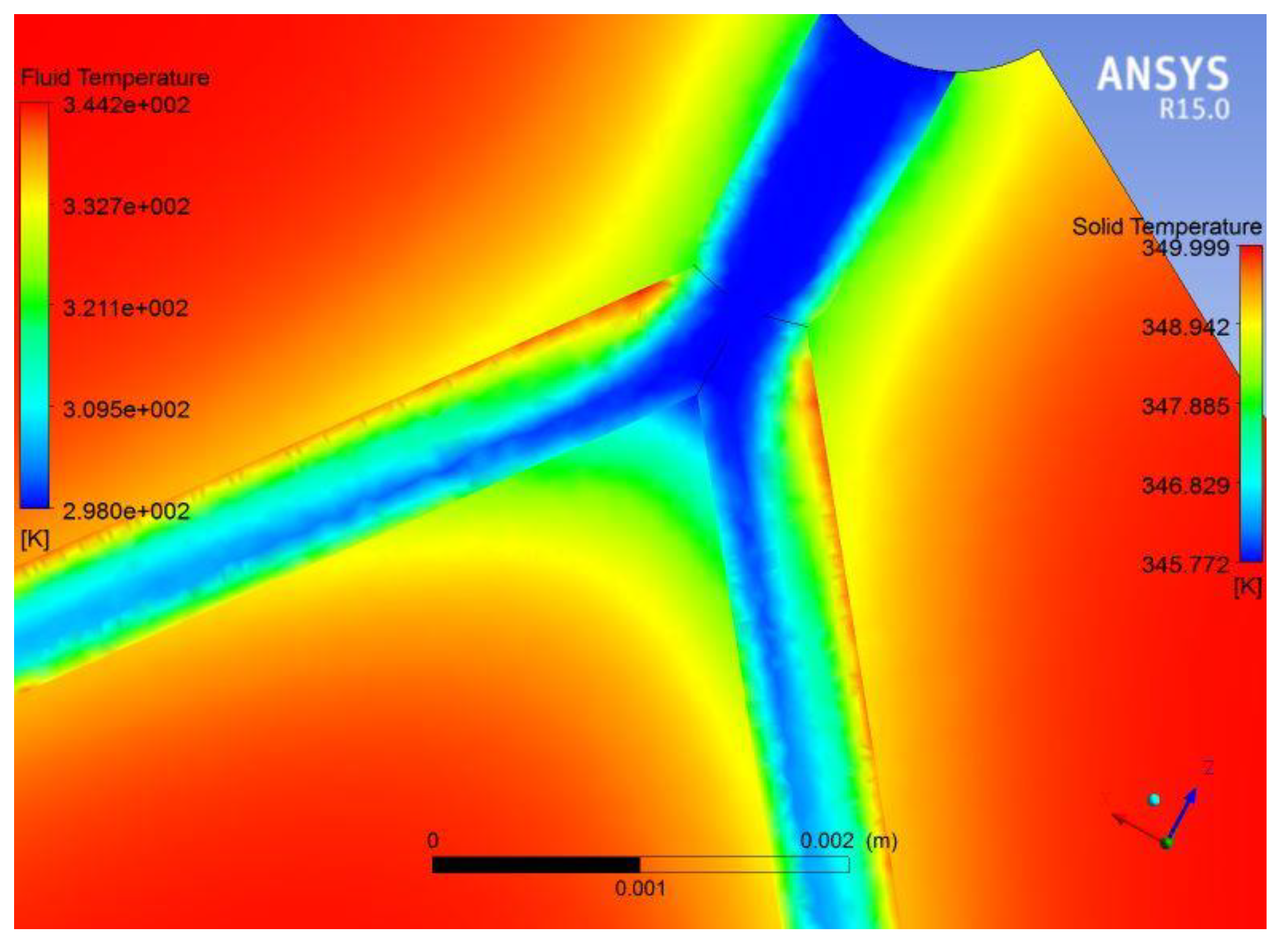
Investigators have taken different approaches to determining the solution: in general, global design optima have been identified either by fixing the fluid regime inside of the channels or recurring to some “allometric” formulae that define δj the and/or the λj for a given δ0 (an allometric correlation is one in which the scaling relationship between some relevant attribute and a characteristic length of the problem depends on some power of the characteristic length itself. For example, in biology, it is established opinion that within a certain species or family the metabolic rate depends on the cube of a single characteristic body length). Only a few studies [5,8,9] have investigated the influence of the number of branchings. The few numerical studies available are usually based on a pre-assigned initial choice of z0 and take advantage of the circumferential symmetry of the problem to simulate only a sector spanning 2π/z0 radians (Figure 2) [10,11].
From a designer’s point of view, the problem can be divided in a series of concatenated steps:
- (a)
- For a given thermal load (amount of power required by the fluid), calculate the necessary external load, or vice versa;
- (b)
- Link the thermal load to the external radius of the disc;
- (c)
- Identify the desired branching configuration;
- (d)
- Verify that the load requirements are satisfied.
Point “c” above has been the object of extensive debate in the last decade. Leaving aside the considerations related to the selection of the materials (a choice that has though a direct influence on manufacturing costs), the problem is to find an “optimal” balance between the internal heat exchange coefficient in the channels and the related pressure loss. This is the well-known dilemma of the heat exchanger designer: smaller tubes lead to higher pumping work but a higher heat transfer coefficient. It is thus clear that the selection of the tubes diameters is of paramount importance. For the purpose of this paper, it is irrelevant whether a constant velocity, a constant Reynolds number or any other allometric criterion is selected for the ratio δj of two successive branches: the choice influences the DSHE performance, but there is no a priori proof that one method is better than the other under all circumstances [12,13,14]. Referring the reader to specific comparisons among different choices of δj [3,7,12], we shall adopt in this paper a constant Reynolds number criterion: a perusal of the procedure will though show that other choices can be immediately integrated within the calculations.
More important for the “optimality” of the design is the choice of a proper criterion for the slenderness ratio of successive branches. It is definitely more convenient to impose each length so that the fluid remains inside the “entrance length” zone where—for comparable pressure losses—the Nu is substantially higher.
Notice that the above two choices represent “best practice engineering”, and the possible implicit approximations (e.g., the entry length ratio κGz = Lj/dj) fall well within the responsibility of the designer.
Once δj and κGz have been assigned their value, the DSHE design reduces to a completely deterministic engineering procedure. The procedure rests on the rigorous application of thermo-fluido-dynamics principles and on a careful analysis of the implications of the selected topology (z0, zb) on the global device performance. Section 2 presents a topological description of the disc, Section 3 demonstrates that a physically correct design procedure leads to an under-specified problem (more variables than equations), and Section 4 shows how the imposition of a correct set of common-sense engineering constraints can make the problem well-posed. Section 5 provides two examples of the advantages of a practical application of the procedure.
2. Classification of a Disc Heat Exchanger as to Its Design Purpose
- (a)
- The relevant topological parameters of a DSHE are:
- (b)
- The ratio of the diameters of successive branches, δj = dj+1/dj;
- (c)
- The ratio of successive lengths, λj = Lj+1/Lj;
- (d)
- The inlet shape ratio defined as the ratio of the diameter of the axial inlet tube to the disc radius, διν = din/R;
- (e)
- The initial number of “sectors” in which the disc is subdivided, z0;
- (f)
- The total number of peripheral outlets, zb = 2nz0.
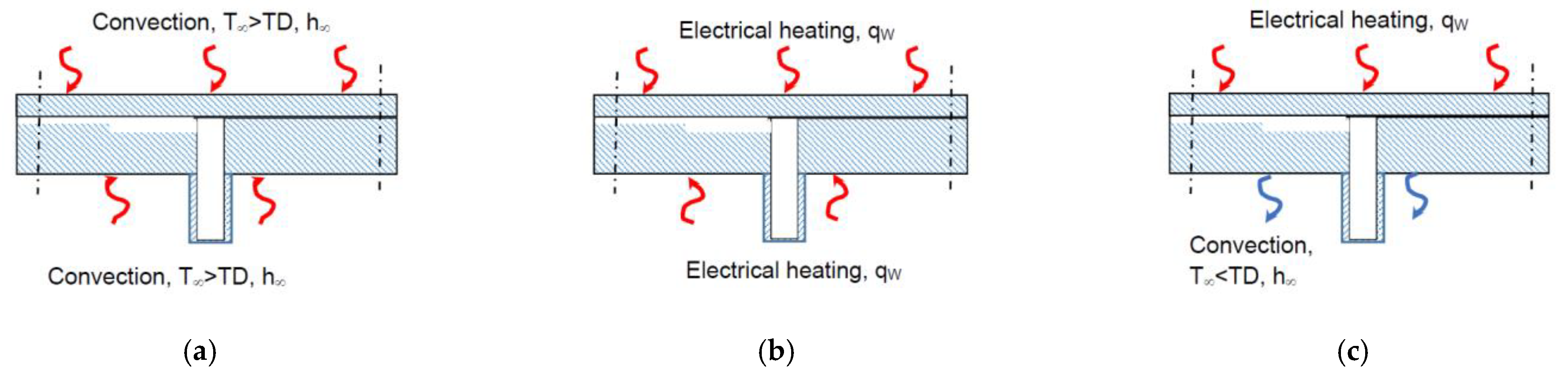
The above parameters define the shape of the DSHE: its size depends obviously on the design specifications. There are two fundamental operational modes that influence the DSHE configuration: either the fluid flowing in the channels cools the disc (i.e., from the point of view of the fluid, the DSHE is a heater), or the fluid is cooled by the disc (the DSHE is a cooler). Hereafter, the “DSHE heater” mode is analyzed, in which the cooling fluid flows through the disc internal channels, and the hot source is either the surroundings (via convection on the DSHE external surfaces, Figure 3a), surface heating by conduction or electrical (Figure 3b), or surface heating on one side and convection cooling on the other side (Figure 3c). In either configuration, the coolant absorbs heat from the bulk material of the disc, which in turn receives a continuous heat influx on one or both of its surfaces.
For such a DSHE-heater, a suitable set of design specifications includes:
- (i)
- The thermal flux qin the DSHE receives by conduction/convection or electrical input;
- (ii)
- The inlet and outlet coolant temperatures Tin and Tout;
- (iii)
- The final ΔT between the disc and the fluid: TD − Tout;
- (iv)
- The average temperature Text of the immediate surroundings;
- (v)
- The density ρf, specific heat cp,f, viscosity µϕ of the coolant;
- (vi)
- The density ρD and specific heat cp,D of the disc material;
- (vii)
- An average heat transfer coefficient for the convection on the outside surface of the disc, hext (if present).
2.1. Thermal Load and DSHE Efficiency
The net heat input Qdes depends on the type of operation, and the formulae related to some illustrative examples of operation are provided in Table 1. Once Qdes is known, the coolant mass flowrate can be calculated from the global energy balance:
where ηDSHE can be approximated as follows:
Incidentally, the numerical value of ηDSHE is not essential for the design procedure outlined here and is reflected only in the ∆T of the working fluid. Notice that Equation (2) shows that the DSHE efficiency depends mainly on the ratio s/R, “s” being the disc thickness: the higher this ratio, the higher the convection losses on the disc peripheral surface. This dependence is not considered in this study, in the sense that s is not considered a relevant variable.
From Equations (1) and (2), and using the formulae indicated in Table 1, one can calculate the mass flow rate of fluid for a given load Qdes, or alternatively the required load given the mass flow rate. In either case, both the efficiency ηDSHE and the external radius R can be directly calculated as well.
Notice that when the above formulae are used for cases (a) and (c) their results are approximate, because the disc is likely to have a radially variable surface temperature, meaning that ΔTD is not a constant but a function of R: if more accuracy is required, the value of R can be calculated iteratively using the final results of the procedure specified below.
2.2. Selection of the Inlet Pipe
A designer would in general select the range of Reynolds number for the inlet flow in such a way as to minimize the pressure losses in an area not involved in the heat exchange. Therefore it is advisable to select Re in the vicinity of the laminar→turbulent transition (where the friction factor is lowest). Once Rein is specified:
The above equations provide the designer with a tentative size R of the disc, with the diameter d0 of the first level of branching and with the required coolant mass flowrate: notice that the diameter din of the inlet tube is not a relevant parameter in the DSHE design, since it depends on the feeding arrangements. On this basis, an “intrinsically feasible”design procedure is described in the next section. There is no “optimization” proper here, because the proposed design procedure uses only fluid-thermodynamic constraint (the constancy of Re and the Graetz assumption, see below), and the feasibility arises simply out of symmetry and of the geometric features of the branchings. But the emerging solution is a very good start for a configuration optimization.
3. The Geometric/Fluid Dynamic Design Is an Underspecified Problem
The first design step is to calculate the diameter of the first branch. To do this, the designer must assign the number of sectors, z0, in which the disc is divided, select a Reynolds number Re0 and then use Equation (4): both choices are obviously arbitrary and may depend on technological issues.
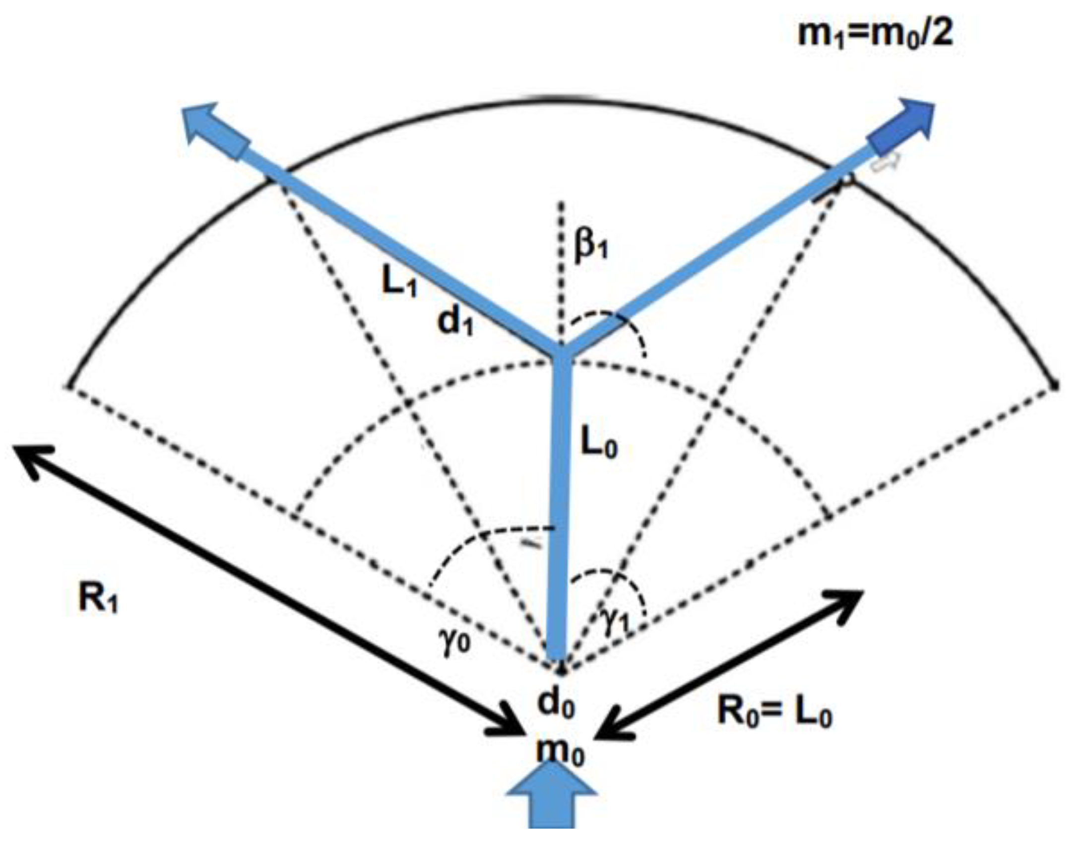
Now, the designer must specify the total number of branchings by assigning the value of the exponent n. This choice is also arbitrary, but an obvious consideration is that the more branchings, the more outlet points there will be on the disc periphery, the more uniform the disc temperature will be and the most effective the cooling. In practice, this choice is limited by technological considerations about the minimum feasible diameter of the smallest branches (see below). Once n has been selected, the configuration of the disc is schematically represented in Figure 4.
For a given surface quality (that depends on material and technological considerations), the internal coefficient of heat transfer in each channel depends on the Nusselt number that in turn is a (non-linearly growing) function of the Reynolds number: for the generic j-th branch:
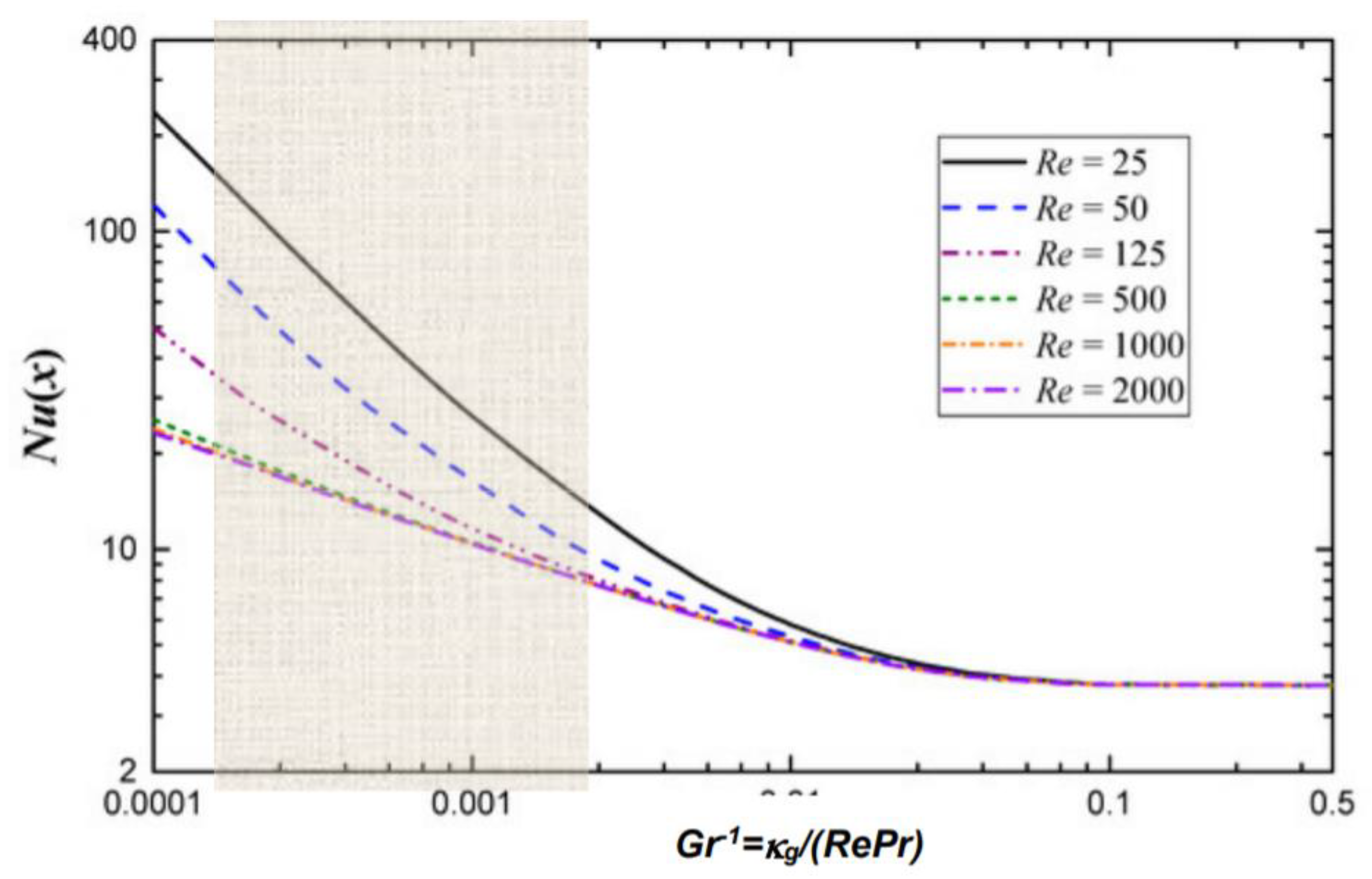
Since it is obviously convenient to have as high a Nuj as possible, a good design choice is to control the slenderness λj = dj/Lj of the channels in such a way that the flow in all of the j branches is within the respective Graetz entry lengths (Figure 5): in other words, Lj = κgdj, with κg falling in the shaded portion of the graph. On the other hand, the friction losses are—under the posited assumptions—also a growing function of Re:
so that the design choice reproduces the well known dilemma of the HE designer: higher pressure losses vs. higher heat transfer coefficient. Previous theoretical work on bifurcated structures [5,13] suggests to impose Rej = Re0, which leads to:
This is the design choice adopted in this paper. Any other selection of dj can be accommodated by the procedure, but of course it modifies the resulting configuration.
Thus, the diameter of the internal channel halves at every new split: this is the reason for which zb has an upper bound, posed both by Equation (6) and by possible technological limitations on the attainable surface roughness. The Graetz ratio must be checked at each level to make sure that it remains in the high-Nu region (Figure 5):
For circular tubes, The Graetz entry length varies between 5 and 15 diameters (kGr = 5 ÷ 15), depending on the boundary conditions on the tube wall and the flow structure. In most practical applications, a value kg ≈ 8–10 is satisfactory, see Section 5 below.
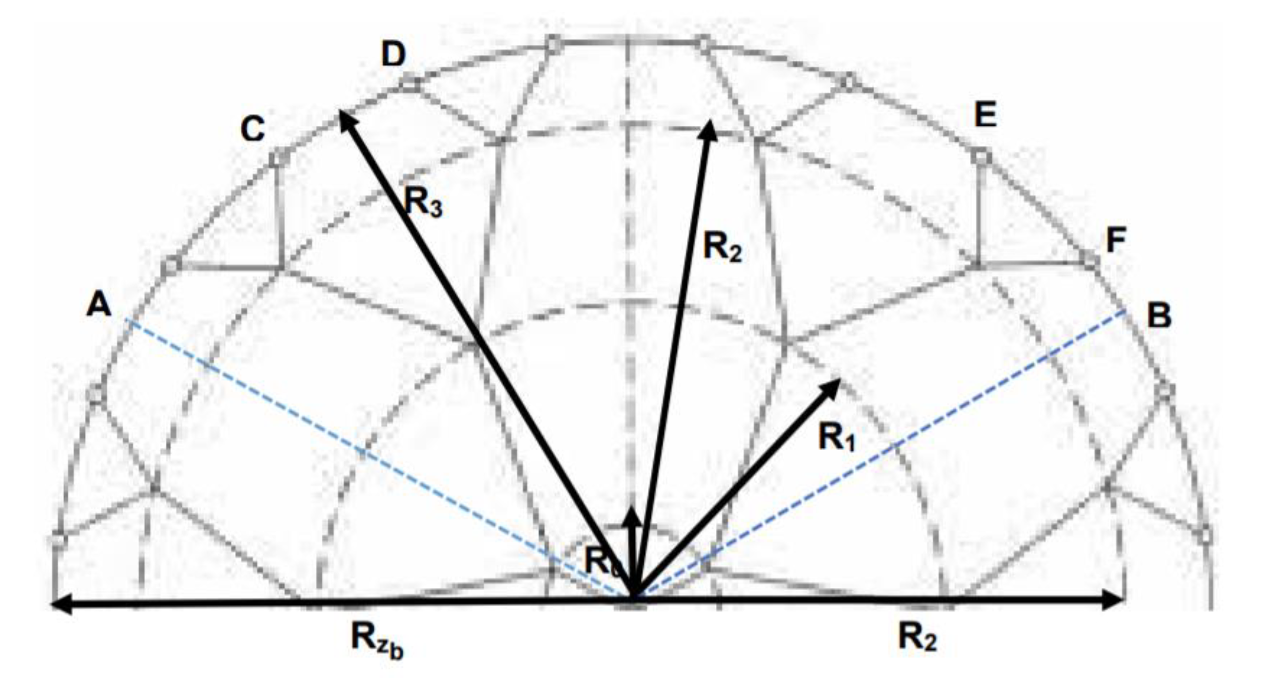
With the geometric parameters thus defined, from simple trigonometric manipulations it follows that the radii of the zb circumferences identified by each splitting level are given by a recursive formula:
A graphical representation for the structures defined by Equation (9) is provided in Figure 6. Equation (9) solves the problem, because Rin, R0, Rzb and d0 are known (Equations (2) and (4)), but it contains zb unknowns, namely, the splitting angles βj. To close the problem, zb−1 auxiliary conditions must be specified.
4. The Proper Additional Constraints
Once the initial number of branches (level 0), z0, and the total number of branchings zb are specified, a series of geometric constraints can be derived that completely defines the configuration by providing an equation for each of the βj. The line of reasoning is as follows: the circular arc at the external radius Rzb defined by γzb will contain (Figure 6) 2zb terminal points, each one being the outlet of a single channel. For all of the terminal points on the circumference to be equispaced, the central angle γzb spanned by two adjacent terminal points (with =) must be equal to . Then by simple trigonometric considerations, and making use of Equations (7) and (8):
where f is an arctan function of the indicated arguments. The set (10) contains zb equations, that together with the second equations in (9) and (2) make the problem position complete (via the solution of a set of trigonometric equation in Rj). Consider that the angles γ0 γj γzb are given by the recursive formula:
5. Examples of Application
To demonstrate the usefulness of the above procedure, two DSHE designs are critically examined here below. Both are real applications, actually built by different teams in one of the thermal sciences laboratories of the University Roma Sapienza between 2017 and 2019. Independently from one other, both configurations were “optimized” according to two different criteria: our goal here is to assess whether these configurations could be improved.
5.1. Comparison of Possible DSHE Configurations for a Glycol/Water Heater
In this application [3,12] the DSHE is cooled by a 50/50 (% mass) mixture of glycol and water. The coolant enters the disc from the axis (Figure 7) and is heated as it flows through the internal channels. The Al-Mn disc receives a uniform heat flux on its bottom surface, the upper one being insulated. The case specifications are listed in Table 2.
The above device has been built and tested, the results being reported in [3,12]. However, application of the procedure described in the previous sections demonstrates that:
- (a)
- The three branches at level 0 are far too short, and therefore the temperature of the portion of the disc within the radius R0 (refer to Figure 6) is bound to be higher-than-optimal, because the heat exchange area z0πd0L0 is too small, even if the Nu0 is here rather high;
- (a)
- Since the branches at levels 1 and 2 do not respect the constant-represcription (the design choice was in this case , i.e., constant velocity in successive branches), there is a disuniformity in the heat transfer (and therefore in the disc bulk temperature) between R1 and R2;
- (c)
- The κGZ is not the same in branches 1 and 2, and this adds up to the non-constant re effect, increasing the disuniformity in the disc body.
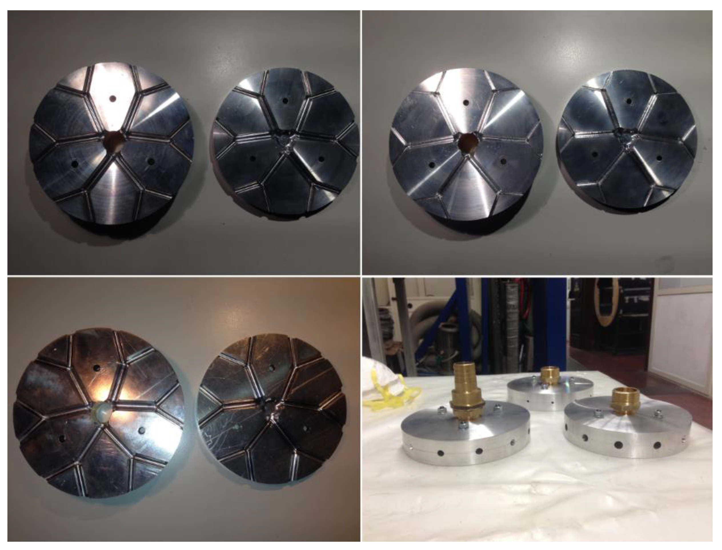
Applying the procedure outlined above, and retaining the same values for the fluid properties, the configuration shown in (Figure 8) is obtained: a slightly smaller size (new external radius 7.0 cm versus the original 7.5), the increased Re and the better allocation of the channel lengths (higher Graetz number) lead to an almost 1 K increase of the fluid exit temperature (304 vs. 303 as reported in [3]).
5.2. Selection of the DSHE Configuration for the Cooling of an Electronic Chip
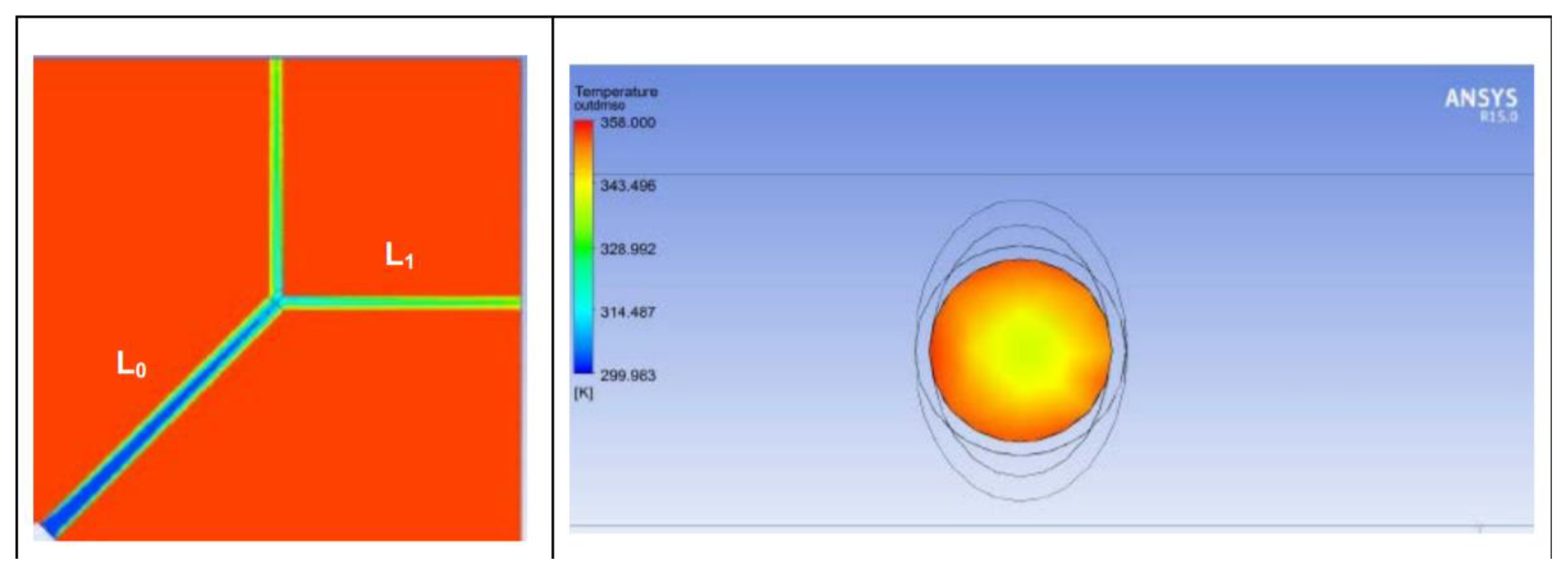
In this application [10] the DSHE is made of an Al-alloy and serves as the cooling unit of an electronic chip. it receives a constant heat flux (72 W) on its upper external surfaces, and it must be designed under the constraint that its upper surface temperature never exceeds 358 K when the disc lower external surface is insulated. The cooling fluid, (dimethylsulfoxide, DMSO) enters the disc from the axis (Figure 9) and flows through two sectors of equal diameter (z0 = 2, each shaped as a single split (zb = 1). Design specifications are listed in Table 3 and Table 4.
The results of the CFD simulation [9] show that:
- (a)
- The level 0 branch is too long: the Graetz number is relatively low, and the (calculated) Nu is about 8;
- (b)
- The branches at level 1 are, on the contrary, too long, and the flow does not become fully developed at the end of the channels (Figure 9, right): the Nu1 is high but the fluid displays a strong radial temperature disuniformity at the outlet;
- (c)
- In spite of the above shortcomings, the temperature of the disc is approximately constant, validating the assumption made in Section 2 as to the external convection loss.
6. Conclusions
A simple procedure for the design of a disc-shaped heat exchanger with internal bifurcated cooling channels is presented and discussed. The goal of this exercise is to show that, while the study of the onset and operation of bifurcated structures in nature requires accurate considerations of optimal energy (exergy) use ratios [5,13,14,15], when it comes to engineered devices it is not always necessary to “mimic Nature”, as many authors (including the present one!) have repeatedly stated. As mentioned in the Introduction, it is necessary to consider the “Interpretation of Nature” and the “Design of a branched heat exchanger” as two quite different activities: the former is a reverse design problem, while the second is obviously a direct one. “Interpreting Nature” involves several highly conceptual steps: first, one must recognize that “similar shapes” exist in natural structures (branching of waterways, of tree twigs, of capillaries in biological tissues, etc.) that are amenable to a common topological representation; then, a set of physical principles must be identified that explains why a certain branched configuration has evolved instead of a linearized one; finally, the conceptual explanation must be proven by extending its generality to the highest possible number of experimentally identified structures. In this sense, the inverse problem is completely falsifiable, because if it fails to explain even one single instance it must be either extended/reformulated to include it or abandoned.
“Design of a branched heat exchanger” is a much simpler engineering exercise, based on diligent scientific considerations, and a small number of prime principles in fluid- and thermodynamics suffice to concoct a sufficiently accurate preliminary design that is as “optimal” as needed. This happens by no chance: in the case of heat exchanger design, examined in this work, the specifications are quite stringent, and if additional symmetries are imposed by the selection of the device shape, the number of “design degrees of freedom” drops to zero. This does not imply that a design activity is devoid of creativity: quite on the contrary, as shown above, a certain degree of “creativity” is naturally embedded in engineering choices that an expert designer would define “obviously proper”, and that are instead the result of an engineering culture (“know-how) that is perceived as being implicit in the designer’s reasoning.
Funding
This research received no external funding.
Institutional Review Board Statement
Not applicable.
Informed Consent Statement
Not applicable.
Data Availability Statement
Not applicable.
Conflicts of Interest
The author declares no conflict of interest.
Nomenclature
| A: m2 | Disc area | p, bar | Pressure |
| cp, J/(kg × K) | Specific Heat | q, W/m2; Q, W | Specific and total heat load |
| d, m | Tube diameter | R, m | Disc radius |
| Gz = RePr/κGz | Graetz number | Re | Reynolds number |
| k, W/(m × K) | Thermal conductivity | s, m | Disc thickness |
| L | Channel length | T | Temperature |
| m | Mass flowrate | U | Equivalent heat transfer coefficient |
| n | Number of levels (“splits”) | z0 | Number of initial branchings |
| Nu = hd/k | Nusselt number | zb | Number of outlets at Rext |
| Greek Symbols | |||
| β | Branching angle | λ = Lj+1/Lj | Channel length ratio |
| γ | Central spanning angle | µ, kg/(ms) | Dynamic viscosity |
| δ = dj+1/dj | Diameter ratio | ν, m2/s | Kinematic viscosity |
| η | Disc efficiency | p, kg/m3 | density |
| κGz = L/d | Graetz factor | ||
References
- Sherman, T.F. On connecting large vessels to small: The meaning of Murray’s Law. J. General. Physiol. 1981, 78, 431–453. [Google Scholar] [CrossRef] [PubMed] [Green Version]
- Bejan, A. Entropy Generation through Heat and Fluid Flow; J. Wiley & Sons: New York, NY, USA, 1982. [Google Scholar]
- Capata, R.; Gagliardi, L. Experimental investigation on the Reynolds dependence of the performance of branched heat exchangers working with organic fluids. Int. J. Heat Mass Transf. 2019, 140, 129–138. [Google Scholar] [CrossRef]
- Miguel, A.F. A study of entropy generation in tree-shaped flow structures. Int. J. Heat Mass Transf. 2016, 92, 349–359. [Google Scholar] [CrossRef]
- Sciubba, E. Entropy generation minima in different configurations of the branching of a fluid-carrying pipe in laminar isothermal flow. Entropy 2010, 12, 1855–1866. [Google Scholar] [CrossRef] [Green Version]
- Sciubba, E. Entropy generation minimization as a design tool. Part 1: Analysis of different configurations of branched and non-branched laminar isothermal flow through a circular pipe. IJoT 2011, 4, 11–20. [Google Scholar]
- Sciubba, E. A critical reassessment of the hess–murray law. Entropy 2016, 18, 283. [Google Scholar] [CrossRef] [Green Version]
- Shah, R.K.; Sekulić, D.S. Fundamentals of Heat Exchangers Design; J. Wiley & Sons: New York, NY, USA, 2003. [Google Scholar]
- Bejan, A.; Alalaimi, M.; Sabau, A.S.; Lorente, S. Entrance-length dendritic plate heat exchangers. Int. J. Heat Mass Transf. 2017, 114, 1350–1356. [Google Scholar] [CrossRef]
- Cancellario, A. Waste Heat Recovery System at Nanoscales: Process Simulation, Optimization, Design of Heat Exchanger. Master’s Thesis, University of Roma Sapienza, Rome, Italy, 2017. [Google Scholar]
- Wechsatol, W.; Lorente, S.; Bejan, A. Dendritic convection on a disc. Int. J. Heat Mass Transf. 2003, 46, 4381–4391. [Google Scholar] [CrossRef]
- Capata, R.; Beyene, A. Experimental evaluation of three different configurations of constructal disc-shaped heat exchangers. Int. J. Heat Mass Transf. 2017, 115, 92–101. [Google Scholar] [CrossRef]
- Sciubba, E. Shape from function: The exergy cost of viscous flow in bifurcated diabatic tubes. Energy 2020, 213, 118663. [Google Scholar] [CrossRef]
- Silva, A.K.; Bejan, A. Dendritic counterflow heat exchanger experiments. Int. J. Thermal Sci. 2006, 45, 860–869. [Google Scholar] [CrossRef]
- Bejan, A. Constructal-theory network of conducting paths for cooling a heat generating volume. Int. J. Heat Mass Transf. 1997, 40, 799–816. [Google Scholar] [CrossRef]
Figure 1.
Sketch of a disc-shaped heat exchanger (a): highly-branched; (b): assembly; (c) single-branched configuration.
Figure 1.
Sketch of a disc-shaped heat exchanger (a): highly-branched; (b): assembly; (c) single-branched configuration.

Figure 2.
“Typical” CFD of a DSHE. Reprinted with permission from Ref. [12]. Copyright 2017 Elsevier.
Figure 2.
“Typical” CFD of a DSHE. Reprinted with permission from Ref. [12]. Copyright 2017 Elsevier.

Figure 3.
Fundamental modes of operation of a DSHE: (a) Convection both sides; (b) Conduction both sides; (c) Conduction and convection.
Figure 3.
Fundamental modes of operation of a DSHE: (a) Convection both sides; (b) Conduction both sides; (c) Conduction and convection.

Figure 4.
DSHE nomenclature (here, z0 = 3, zb = n = 1, γ0 = 60°).

Figure 5.
Nusselt number vs. Graetz number.

Figure 6.
Identification of the radii of successive branchings (here, z0 = 3, zb = 3).


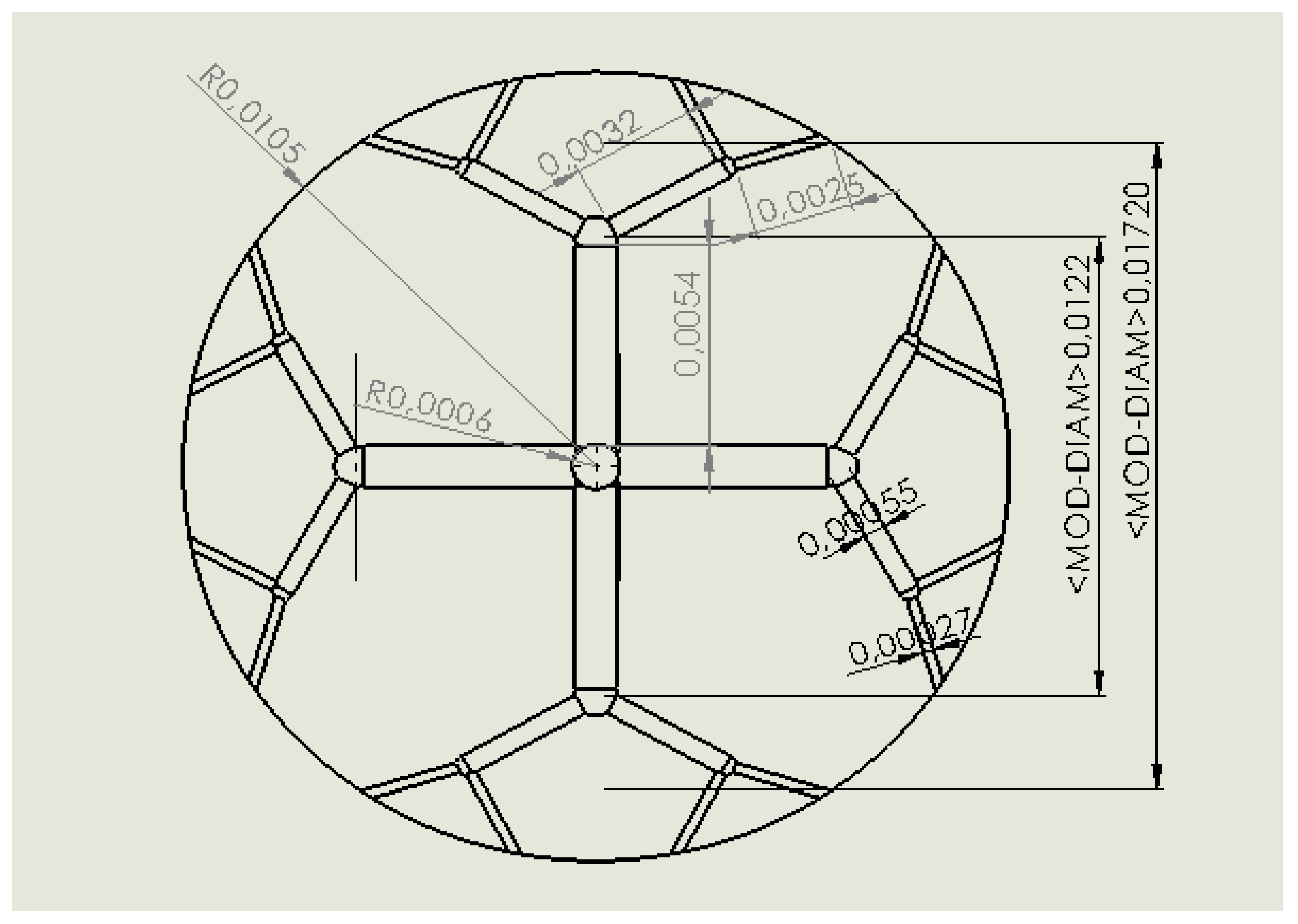
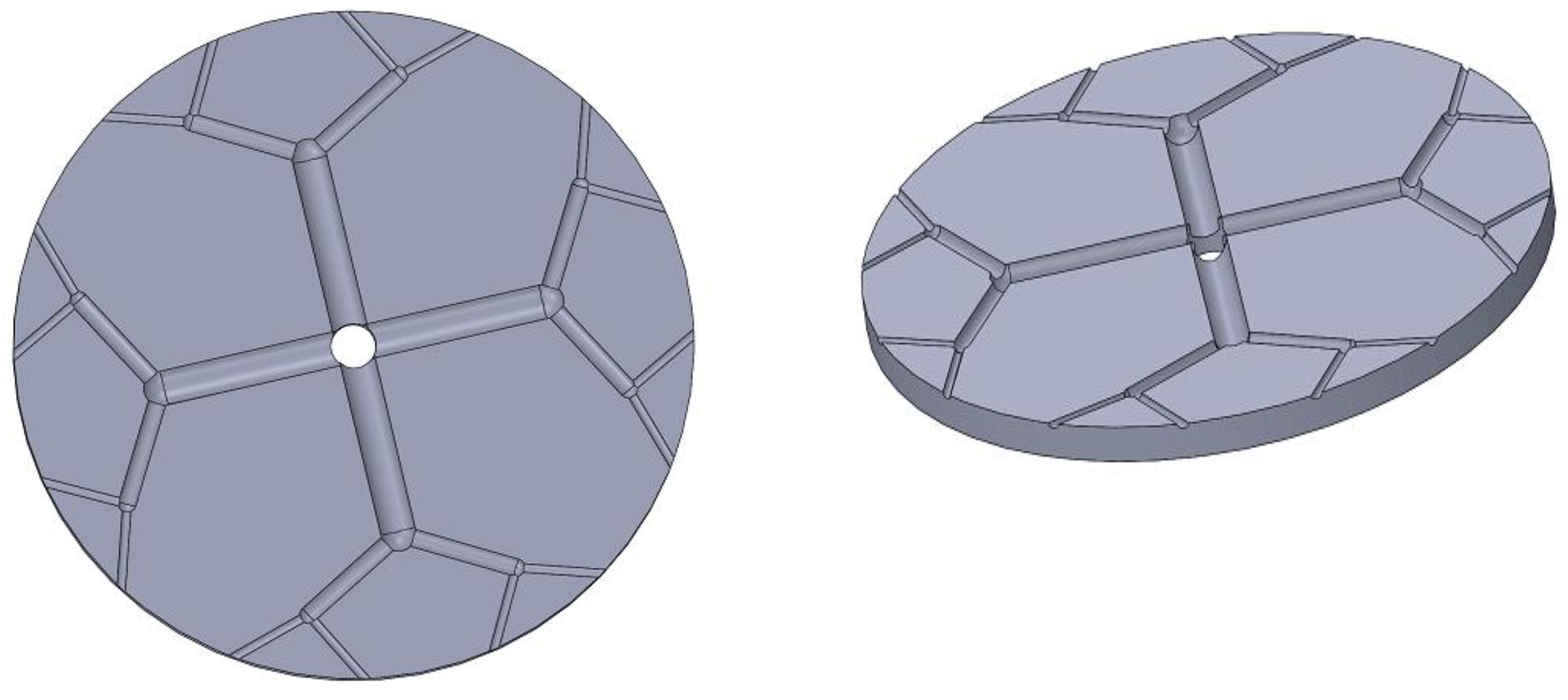
Figure 8.
The improved DSHE-C1 (above) and two 3–D renderings.

Figure 9.
Ultra-micro DSHE: Results of a RANS CFD simulation (Adapted from Ref. [10]).
Figure 9.
Ultra-micro DSHE: Results of a RANS CFD simulation (Adapted from Ref. [10]).

Figure 10.
The improved ultra-micro DSHE-C2.

Figure 11.
Two 3–D renderings of the improved DSHE-C2.


Table 1.
Definition of the design DSHE thermal load.
| Type of Operation (Heater) | Needed Design Specifications | QDES |
|---|---|---|
| Heat input by convection on both sides | hext, Text, TD | |
| Electrical or conduction heating on both sides | qin, sD, kD | |
| Electrical or conduction heating on one surface, cooling by free convection on the opposite one | hext, Text, TD, qin, sD, kD |
Table 2.
An Al/Mn alloy DSHE cooled by a glycol/water mixture (Data adapted from [3]).
Table 2.
An Al/Mn alloy DSHE cooled by a glycol/water mixture (Data adapted from [3]).
| Disc Radius, m | 0.075 | Glycol Mix Mass Flowrate, kg/s | 0.181 |
| Disc Thickness, m | 0.015 | Glycol Mix Density at Inlet, kg/m3 | 1088 |
| Number of Root Splits, Z0 | 3 | Glycol Mix Viscosity at Inlet, m2/s | 5.97 × 10⁻⁶ |
| Branching Exponent, Zb | 2 | Glycol Mix Conductivity kW/(m × K) | 0.65 |
| Dfeed, M | 0.022 | Glycol Mix Specific Heat, J/(kg × K) | 870 |
| D0, M | 0.013 | Tglycol,In, K | 300 |
| D1, M | 0.0065 | Tglycol,Out, K | 303 |
| D2, M | 0.00325 | Texternal Air, K | 293 |
| L0, M | 0.011 | Qelectr, W | 500 |
| L1, M | 0.048 | LMTD, K | 6.38 |
| L2, M | 0.024 | Uavg, W/(m2 × K) | 7227 |
| ReCHANNELS | 913 | ηDSHE | 0.91 |
Table 3.
Improved design of the DSHE of example 5.1.
| Disc Radius, m | 0.084 | L0, M | 0.030 |
| Disc Thickness, m | 0.015 | L1, M | 0.031 |
| Number of Root Splits, Z0 | 3 | L2, M | 0.033 |
| Branching Levels, N | 2 | TGLYCOL, IN, K | 300 |
| Total Number of Fluid Outlets, Zb | 12 | TGLYCOL, OUT, K | 304 |
| Dfeed, m | 0.022 | TEXTERNAL AIR, K | 293 |
| D0, m | 0.0059 | QELECTR, W | 500 |
| D1, m | 0.0029 | LMTD, K | 6.66 |
| D2, m | 0.00148 | Uavg, W/(m2 × K) | 14,400 |
| RECHANNELS | 2000 | ηDSHE | 0.91 |
Table 4.
A DMSO-cooled ultra-micro DSHE.
| Disc Radius, m | 0.052 | DMSO Mass Flowrate, kg/s | 7.84 × 10⁻⁴ |
| Disc Thickness, m | 0.001 | DMSO Mix Density at Inlet, kg/m3 | 1101 |
| Number of Root Splits, Z0 | 2 | DMSO Mix Viscosity at Inlet, m2/s | 1.8 × 10⁻⁶ |
| Branching Exponent, N | 1 | DMSO Mix Conductivity K, W/(m × K) | 0.16 |
| Dfeed, M | 0.0012 | DMSO Mix Specific Heat, J/(kg × K) | 1960 |
| D0, M | 0.0011 | Tdmso,In, K | 298 |
| D1, M | 0.00055 | Tdmso,Out, K | 352 |
| L0, M | 0.0123 | Texternal Air, K | 300 |
| L1, M | 0.0093 | Tdisc, W | 358 |
| Rein | 209 | Qload, W | 72.22 |
| Re1 | 694 | LMTD, K | 35 |
| Re2 | 968 | Uavg, W/(m2 × K) | 35,400 |
Table 5.
Improved design of the ultra-micro DSHE.
| Disc Radius, m | 0.01 | L0, m | 0.0055 |
| Disc Thickness, m | 0.001 | L1, m | 0.0043 |
| Number of Root Splits, Z0 | 4 | L2, m | 0.0034 |
| Branching Exponent, N | 1 | Tdmso, In, K | 298 |
| Total Number of Fluid Outlets, Zb | 8 | Tdmso, Out, K | 345 |
| Dfeed, m | 0.0012 | Texternal Air, K | 300 |
| D0, m | 0.0011 | Qelectr, W | 72.22 |
| D1, m | 0.00055 | LMTD, K | 31 |
| D2, m | 0.00027 | Uavg, W/(m2 × K) | 2973 |
| RECHANNELS | 115 | Rein | 839 |
Publisher’s Note: MDPI stays neutral with regard to jurisdictional claims in published maps and institutional affiliations. |
© 2022 by the author. Licensee MDPI, Basel, Switzerland. This article is an open access article distributed under the terms and conditions of the Creative Commons Attribution (CC BY) license (https://creativecommons.org/licenses/by/4.0/).
Share and Cite
MDPI and ACS Style
Sciubba, E. How to Reduce the Design of Disc-Shaped Heat Exchangers to a Zero-Degrees-of-Freedom Task. Energies 2022, 15, 1250. https://doi.org/10.3390/en15031250
AMA Style
Sciubba E. How to Reduce the Design of Disc-Shaped Heat Exchangers to a Zero-Degrees-of-Freedom Task. Energies. 2022; 15(3):1250. https://doi.org/10.3390/en15031250
Chicago/Turabian StyleSciubba, Enrico. 2022. "How to Reduce the Design of Disc-Shaped Heat Exchangers to a Zero-Degrees-of-Freedom Task" Energies 15, no. 3: 1250. https://doi.org/10.3390/en15031250
Note that from the first issue of 2016, this journal uses article numbers instead of page numbers. See further details here.