Article

Effects of an Unsteady Morphing Wing with Seamless Side-Edge Transition on Aerodynamic Performance

by
Chawki Abdessemed
1,*,
Abdessalem Bouferrouk
2 and
Yufeng Yao
2
1
Propulsion Engineering Centre, School of Aerospace Transport and Manufacturing, Cranfield University, Bedfordshire MK43 0AL, UK
2
School of Engineering, University of the West of England, Coldharbour Lane, Frenchay, Bristol BS16 1QY, UK
*
Author to whom correspondence should be addressed.
Energies 2022, 15(3), 1093; https://doi.org/10.3390/en15031093
Submission received: 21 December 2021 / Revised: 20 January 2022 / Accepted: 29 January 2022 / Published: 1 February 2022
(This article belongs to the Special Issue Modelling of Aerospace Vehicle Dynamics)

Abstract

:
This paper presents an unsteady flow analysis of a 3D wing with a morphing trailing edge flap (TEF) and a seamless side-edge transition between the morphed and static parts of a wing by introducing an unsteady parametrization method. First, a 3D steady Reynolds-averaged Navier–Stokes (RANS) analysis of a statically morphed TEF with seamless transition is performed and the results are compared with both a baseline clean wing and a wing with a traditional hinged flap configuration at a Reynolds number of 0.7 × 10⁶ for a range of angles of attack (AoA), from 4° to 15°. This study extends some previous published work by examining the inherent unsteady 3D effects due to the presence of the seamless transition. It is found that in the pre-stall regime, the statically morphed wing produces a maximum of a 22% higher lift and a near constant drag reduction of 25% compared with the hinged flap wing, resulting in up to 40% enhancement in the aerodynamic efficiency (i.e., lift/drag ratio). Second, unsteady flow analysis of the dynamically morphing TEF with seamless flap side-edge transition is performed to provide further insights into the dynamic lift and drag forces during the flap motions at three pre-defined morphing frequencies of 4 Hz, 6 Hz, and 8 Hz, respectively. Results have shown that an initially large overshoot in the drag coefficient is observed due to unsteady flow effects induced by the dynamically morphing wing; the overshoot is proportional to the morphing frequency which indicates the need to account for dynamic morphing effects in the design phase of a morphing wing.

1. Introduction

The aircraft industry has been under increasing pressure to move towards “Greener and Quieter” aircraft design through various frameworks, such as FlightPath 2050 [1]. However, modern aircrafts are reaching near peak levels of aerodynamic efficiency (such as lift-to-drag ratio) making any further improvement of current configuration a daunting task, if not impossible. Therefore, designers have been striving to re-imagine the present-day aircraft by employing innovative technologies, such as adaptive morphing structures for flight optimisation and flow control [2,3,4]. The benefits and challenges of morphing structures are well documented in the literature [5,6] and various reviews have been produced [7,8]. In the aerospace sector, researches on morphing concepts are very wide and varied, ranging from concepts on fighter aircraft [9], regional aircraft [10,11], hovering micro air vehicles [12] and general aircraft [13,14].
The use of morphing lifting surfaces for in-flight flow control can result in considerable drag reduction during the cruise [15,16,17], given the fact that a morphing trailing-edge flap (TEF) will seal the flap side-edge gaps, eliminating small pockets that are known for their high vorticity and for being a significant source of airframe noise [18]. The enhancement in the wing efficiency arising from the possible reduction of drag would contribute directly to a reduction of specific fuel consumption [7,8] and to the sustainability of future aircraft, paving the way not only to zero carbon emission goals for aviation, but also for applications in other fields, especially in renewable energy generation applications, such as wind energy (morphing wind turbines [19]) or tidal energy, where morphing blades could help to mitigate unsteady thrust while sustaining the mean harvested power [20].
Several approaches have been proposed to seal the flap side-edge gaps, such as the concept presented by Khorami et al. [21] where elastically deformable structures are introduced at each side-edge to passively deform along with the flap movements and thus seal the gaps. Another concept is the one developed by FlexSys Inc. under NASA’s Adaptive Compliant Trailing Edge (ACTE) project [22,23]. The high-lift flaps of a Gulfstream III business jet were replaced by a morphing transition structure with a compliant fairing at the ends of each flap to seal the gaps, and subsequent flight tests of this concept have demonstrated that it is possible to reduce aircraft noise by as much as 30% [24]. However, this concept does not offer a smooth geometry transition at the trailing edge, which could still be a source of disturbance in the flow. Recently, Woods et al. [25] presented a design for a compliant morphing flap that offers a smooth geometry transition, with an additional advantage being that the design can be integrated with the Fish Bone Active Camber (FishBAC) morphing airfoil [26].
On the numerical side, comparatively more work has been undertaken to quantify the aerodynamic efficiency of morphing concepts. Starting with optimisation problems using low-fidelity panel-based methods by Molinari et al. [27] or the Vortex-Lattice Methods (VLM) by Obradovic et al. [28] and Koreanschi et al. [29], the Reynolds-Averaged Navier-Stokes (RANS) solver, coupled with various turbulence models, has also been applied for morphing wings applications, e.g., Lyu et al. [30] have used the Spalart-Allmaras turbulence model with up to 5% drag reduction achieved. Finally, Jawahar et al. [31] used a hybrid RANS-LES approach, so-called Detached Eddy Simulation (DES), to study the aerodynamic and aeroacoustic flow around an airfoil with a rigid and morphing TEF. An increase of up to 13% in the CL,max was observed, but with a significant drag penalty that reduced the overall aerodynamic efficiency by 4%.
When it comes to flap side-edge studies, Woods et al. [25] provided initial qualitative results of a morphing concept with a seamless transition. It was found that the use of this concept can significantly reduce the pressure leakage from the lower wing surface to the upper wing surface, resulting in an improvement of aerodynamic performance. This is supported by a further study which compared the same morphing concept with a traditional unsealed configuration using both CFD and experimental methods, and results showed that up to 18% gains in aerodynamic efficiency is achievable [32]. Most recently, Rivero et al. [33] performed a quasi-2D wind-tunnel test to investigate the aerodynamic performance of a FishBAC morphing flap and compare it with a hinged flap configuration. Experimental results showed that the quasi-2D morphing flap was able to produce an over 50% improvement in the lift-to-drag ratio (L/D) at moderate to high lift coefficients where the flap device is significantly deflected, and an at least 16% higher lift-to-drag ratio at all lift coefficients, even for the lowest deflection values (~10°).
All of the studies surveyed to date have simplified the wing morphing to be a statically morphed wing configuration, thereby overlooking the dynamic effects that deforming motion of the TEF might have on the flow field and its subsequent contribution to the airframe noise. Abdessemed et al. [34,35,36,37,38] have previously introduced a framework to study 2D unsteady morphing airfoils by modifying a parametrization method to include a time variable and integrating it into a high-fidelity RANS solver [39] with the help of an in-house developed user-defined function (UDF) routine [40] to accommodate a dynamic meshing for mesh deformation. Nevertheless, to capture the physics of real-life morphing wings, the problem needs to be considered in 3D, allowing the turbulence to be properly resolved, and a more realistic morphing concept to be modelled, particularly the spanwise effects on the flow field.
The focus of this paper is therefore twofold: firstly, a comparative steady RANS analysis is presented between a wing equipped with a morphing TEF and a seamless transition already deflected (i.e., statically morphed), and a wing with a conventional hinged flap and unsealed side-edge gaps. The seamless transition is based on a recent concept, known as Morphing Elastically LofteD (MELD), introduced by Woods et al. [25], which still lacks quantitative performance analysis. Secondly, an extension to the above work by investigating the unsteady aerodynamic effects of a morphing wing [34,35,36,37] is proposed in order to study a dynamically morphing TEF with a seamless side-edge transition (where the TEF deforms continuously from a baseline position to a final deflection). A modified seamless transition function is proposed and used to model the transition between the static and morphing parts of the wing. Finally, the aerodynamic performance of a dynamically morphing TEF is investigated for three morphing frequencies of 4 Hz, 6 Hz and 8 Hz to understand their impacts on the aerodynamic performance.

2. Problem Definition

Two cases based on the NACA0012 section profiles are investigated in this work; first, a steady RANS modelling of 3D wing with a statically morphed TEF is compared with 3D wing with a conventional hinged flap, whilst the second case will investigate a 3D wing with dynamically morphing TEF using a newly modified parametrization method [41]. All configurations are studied at a Reynolds number of Re = 0.7 × 10⁶, based on the wing section airfoil chord length (c), and a Mach number of 0.115. A range of Angles of Attack (AoA) from 4° to 15° is considered for the steady flow analysis and the results at AoAs = 6° and 8° are presented for the dynamically morphing TEF at three morphing frequencies of 4 Hz, 6 Hz and 8 Hz, respectively. These frequencies correspond to the morphing deflection speed by which the flap deflects to the imposed final defection position, and they are inspired by previous experimental work [42] while taking into account the amount of computational resource required, e.g., a reduced time step with an increased frequency.

2.1. Unsteady Geometry Parameterization of a Dynamically Morphing TEF

In order to model the deformation of a wing, it is important to define the mathematical formulae in time to consider such deformations. For the present problem, two parametrization methods are adopted. The TEF deformation is parametrized using the modified method [36,43], introduced in a reference paper [44], and re-written in Equations (1) and (2), respectively. The unsteady camber distribution is then added to the NACA 0012 thickness distribution in order to obtain the desired deformation.
y t = ( t h 0.2 ) (   0.2969 x ¯ 0.1260 x ¯ 0.3516   x ¯ 2 + 0.2843 x ¯ 3 0.1015 x ¯ 4   )
y c = { 0     , 0 x ¯ < x s   a n d   0 t   T 4 w t e s i n ( 2 π t T ) ( x ¯ x s ) 3 ( 1 x s ) 3 ,     x ¯ x s   a n d   0 t   T 4 w t e ( x ¯ x s ) 3 ( 1 x s ) 3     , x ¯ x s   a n d   t >   T 4
where   y c   and   y t are the camber and thickness distributions, respectively, th is the maximum airfoil thickness, wte is the non-dimensional value of maximum vertical deflection at the TE, T is the morphing period and xs is the streamwise location along the airfoil chord (at 75% chord for all subsequent studies in this paper) for the morphing to start and x ¯ is the non-dimensional distance along the chord.
Moving from 2D to 3D raises the issue of implementing an unsteady parametrization to model the flap side-edge transition between the morphing and non-morphing parts. Woods et al. [25] proposed a simple parametric formula (Equation (3)) which yields a smooth continuous profile suitable for this application, but viable only for the statically morphing case.
w t e ( z ¯ ) = h   cos ( π z ¯ l ) h
where w t e ( z ¯ ) is the vertical TEF displacement for the transition part, z ¯ is the non-dimensional transition distance along the span and h is the half-amplitude of the control surface deflection and l is the non-dimensional spanwise length of the morphing portion of transition.
In the camber distribution defined in Equation (2), wte is a constant, but when a seamless distribution is required, the vertical displacement of the TEF is dependent on the spanwise coordinate z ¯ . Therefore, unsteady camber distribution for the seamless transition portion ( x ¯ x s ) during the morphing ( t s t a r t t T 4 ) is written as in the following:
y c = { w t e ( z ¯ ) sin ( 2 π ( t t s t a r t ) T ) ( x ¯ x s ) 3 ( 1 x s ) 3 , t r s t a r t z ¯   t r e n d 0                     ,   z ¯   t r s t a r t   o r z ¯   t r e n d
where t is time and T is the complete morphing period of the TEF motion, trstart and trend are the spanwise transition start and end locations respectively. At t = tstart the morphing commences, and the flap is deflected until it reaches the maximum deflection value of h, thus representing the deforming motion. The morphing flap uses the same camber definition as defined in Equation (2). It is noted that with the current parametrization a small elongation of the chord length is observed (0.001%), however it was assumed that the impact on the aerodynamics of the wing is negligible.
Figure 1 illustrates the final geometry resulting from the implementation of the proposed 3D parametrization method at three instantaneous time stages. It clearly illustrates the gradual morphing from the baseline wing (left) to the final morphed wing with a seamless side-edge transition (right).

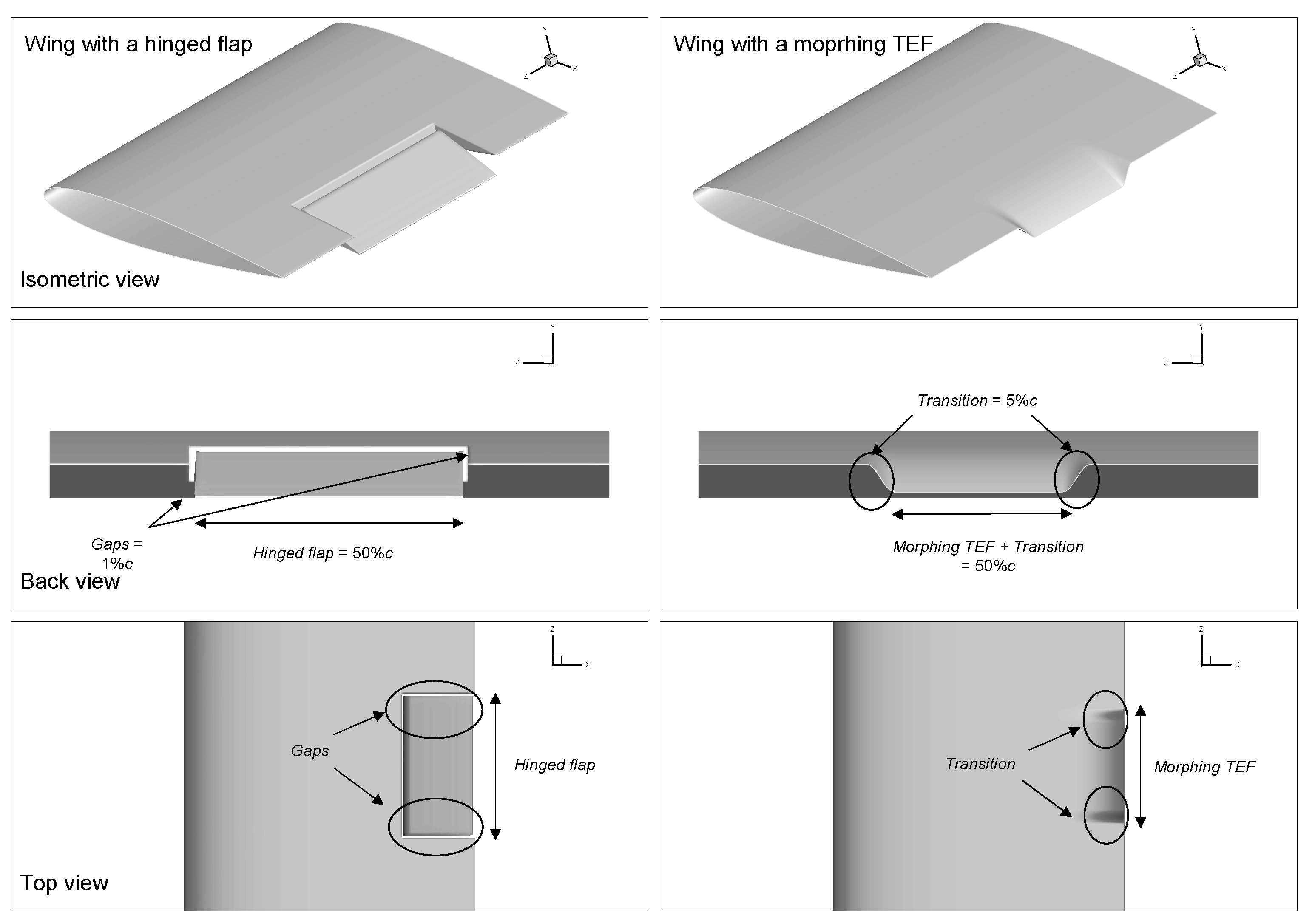
2.2. RANS Study of a Statically Morphed TEF vs. a Hinged Flap

To check the performance of a morphing flap design compared with a standard hinged flap, RANS flow analysis is performed to study the differences in the aerodynamic behaviour between a seamless transition flap with a sealed side-edge gap and a conventional hinged flap. A rectangular NACA 0012 wing demonstrator with a chord length c = 0.2286 m and a span S = 0.2286 m was investigated. Furthermore, the two side walls of the wings were treated as symmetry planes which effectively simulate a 2D wing with an infinite span similar to a 2D airfoil.
The statically morphed TEF was set to be 40% of the span with 5% allocated to each side of the transition, and the remaining 50% of the span is the non-morphing part. The same proportion (40%) is used for the wing with a hinged flap, where all side-edge gaps have a width of 1% of the chord c, and the remaining 58% of the span is static part. The flap trailing edges in both wings were deflected to the same position, i.e., a vertical distance of 5% of the chord (approximately equal to 14° flap deflection angle). To gain further insight into how the flap movements affect the aerodynamic performance, steady RANS CFD was performed for the baseline NACA 0012 wing. Figure 2 summarizes all configurations studied while Figure 3 illustrates the 3D view of the morphed and hinged flap wing concepts. It is worth mentioning that a plane flap design for the hinged flap was chosen in order to provide comparable size to the morphing TEF even though it is not the optimal aerodynamic design, as opposed to built-in or split flaps, for instance.

Experimental Data

As suggested by Holst et al. [45], there is a lack of quality data in the post stall region for nearly every airfoil. However, the experimental data used in this work is one of the most referenced and cited full range data sets, originating from measurements performed at the Sandia National Laboratories by Sheldahl and Klimas [46]. Although Sheldahl and Klimas provided airfoil data for low Reynolds numbers, some of their data were based on the airfoil section characteristic synthesizer computer code PROFILE. Therefore, for a NACA 0012 airfoil, the data for a Reynolds number Re = 0.86 × 10⁶ were used for comparison, as is they are the only data that are obtained purely from experimentation and they have not been extrapolated from higher Reynolds numbers. All experimental data were obtained with increasing AoA to 180 °. Lift, drag, and moment data were obtained from the balance system, with appropriate corrections (e.g., wake and wall blockage, buoyancy, upwash, and wind-turbulence factor, etc.). Further details regarding the experimental setup can be found in the reference paper [46].

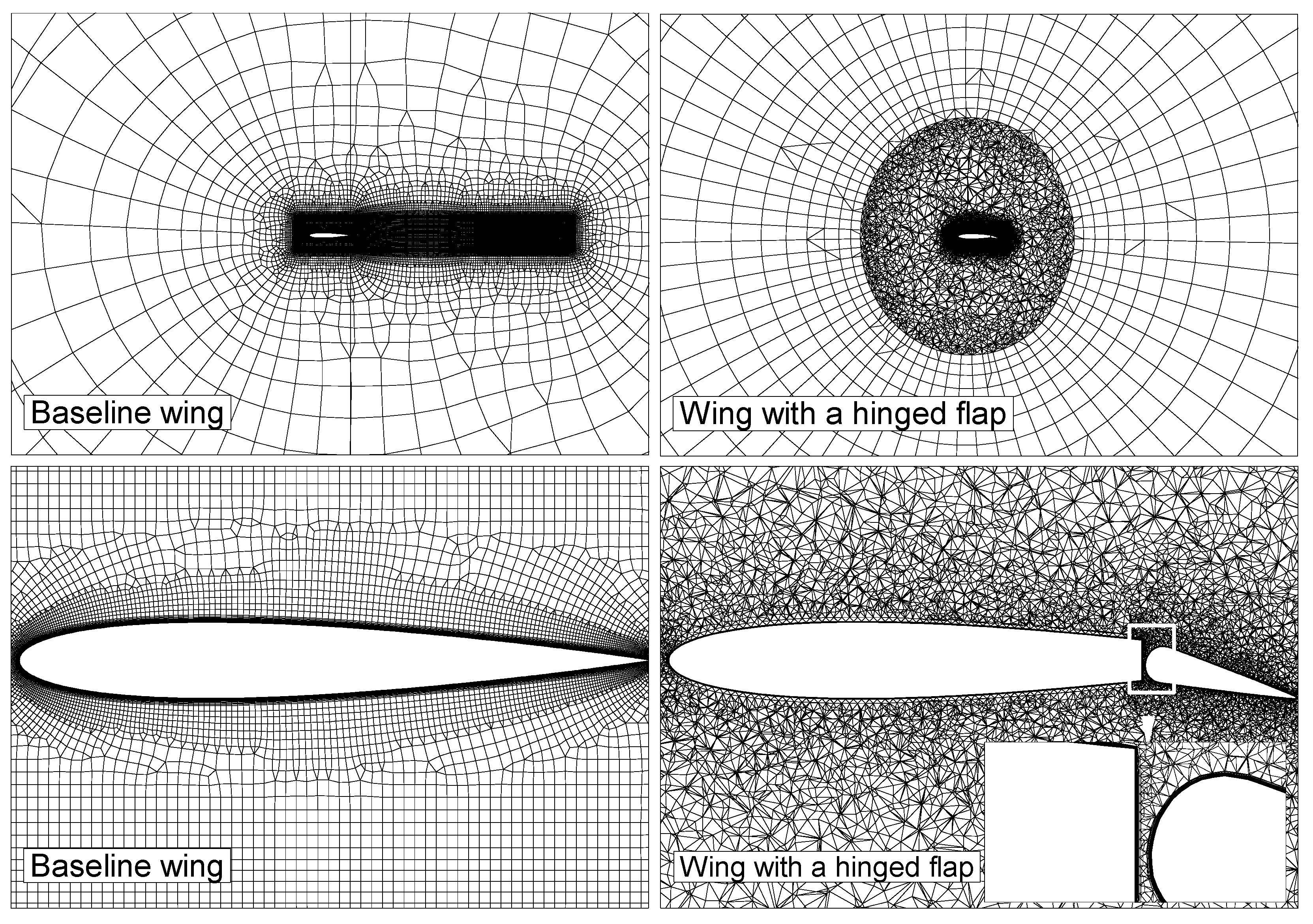
3. Computational Setup

3.1. Steady RANS

Steady RANS modelling using the software package ANSYS Fluent is conducted for the cases mentioned. A series of grids is generated around each configuration with the number of cells ranging between 2–4 million cells, and refined grids are placed around the wing surface and wake region. The far-field is placed at least 15 chord lengths away from the wing trailing edge. A maximum near-wall first-layer grid resolution of y+ < 1 is targeted with a minimum of 50 prism layers to properly capture the boundary layer. Hybrid grids (consisting of a prism layer covering the boundary layer and tetrahedral elements outside) are favoured for cases where the geometries have gaps or if the geometry is deforming. Hybrid grids are faster to generate while keeping good mesh quality metrics. Furthermore, having tetrahedral elements offers the flexibility to apply local re-meshing to remove any highly skewed elements. Finally, a quad dominant C-grid is generated for the statically morphed wing, giving the relative simplicity of the geometry. Figure 4 illustrates the computational domains used.
In order to achieve the mesh independent solution, a grid sensitivity analysis has been conducted using three different meshes of coarse, medium and fine resolutions with the number of cells ranging between two to six million cells. Based on the time history of CL and CD, the transition from medium to fine meshes has resulted in an error recovery of less than 1%. Therefore, by considering the grid resolution and computational accuracy and efficiency, the medium mesh (four million cells) has been selected to perform all the subsequent simulations in the present study.
The grids are also created in an iterative manner to be suitable for unsteady flow application, therefore over 90% of the cells have a CFL number around or less than unit, in particular all grid cells in the near field regions around the airfoil have a CFL less than a unit, which is sufficient to capture any significant flow field changes in the present application.
The pressure-velocity coupling is achieved using the coupled algorithm, and the least squares cell based spatial discretization is also used for all gradients calculations. Moreover, the intermittency k-ω SST model is used for turbulence closure, and a second order upwind scheme is utilized for the momentum and turbulence equations discretization. The intermittency k-ω SST has been chosen as it offers a good balance between the accuracy and computational cost, it has been shown that it is perfectly adequate for this type of turbulent separated flow [47], offering better predictions than the Spalart-Allmaras model [48], but at only a fraction of the cost compared to higher fidelity turbulence models, such as the hybrid SBES which has been used in previous published 2D work [37].
In order to eliminate the possible influence of wing tip vortices, the wing is modelled as a semi-infinite wing where the width of the domain matches the span of the studied wing, and a symmetry boundary condition is imposed on the sidewalls of the domain. All simulations are run until the CL and CD statistically converged, and all the residuals dropped below 10−5.

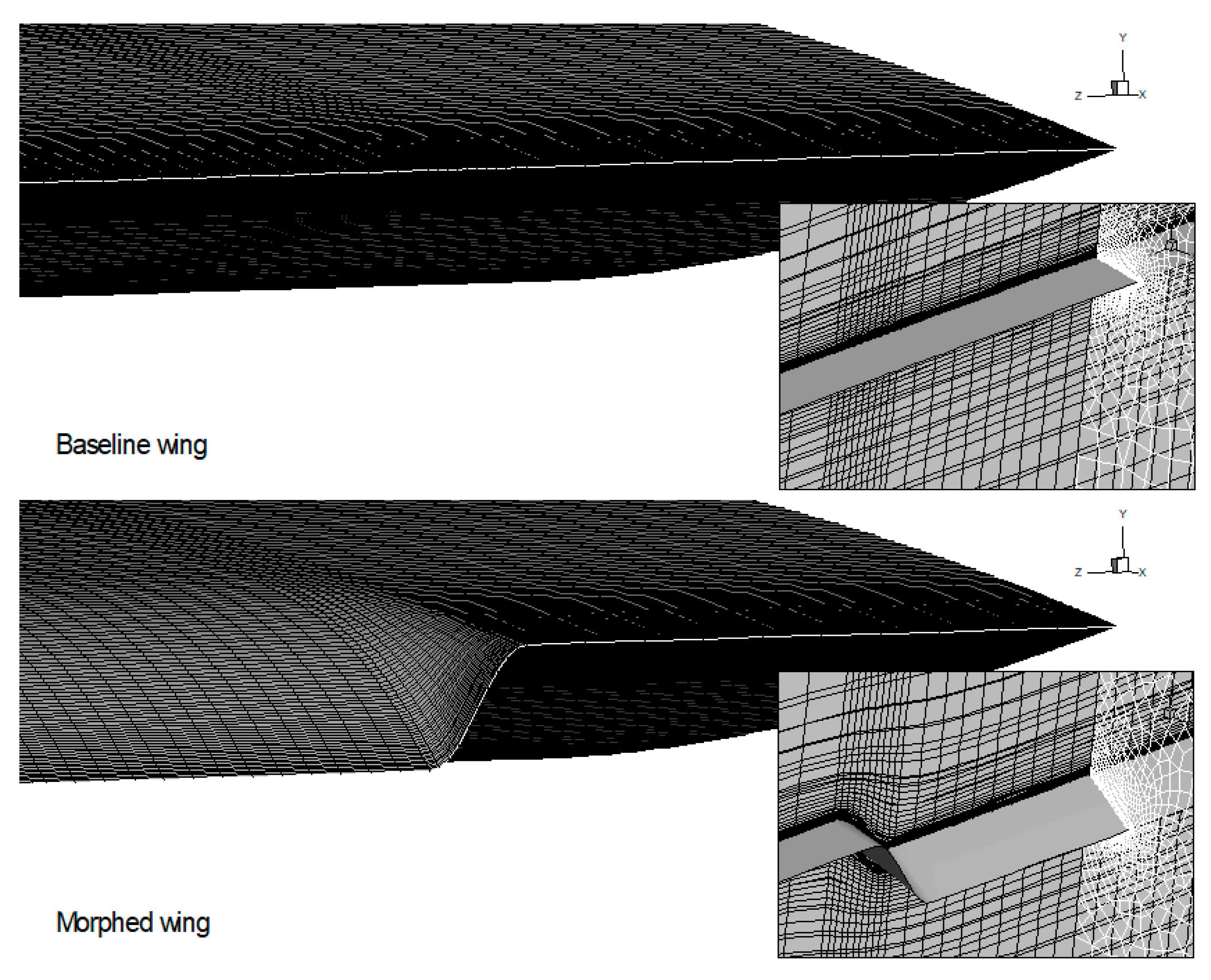
3.2. Unsteady RANS and Dynamic Meshing

Unsteady RANS modelling is performed using the baseline mesh generated for the NACA 0012 wing. It is initialized from the converged steady RANS simulation results and runs until both CL and CD statistically converge before engaging the dynamic meshing solver and starting the wing deformation.
In order to deform the mesh smoothly, a diffusion-based smoothing is applied. This is mainly due to its capability of better preserving mesh quality compared with other smoothing schemes [39,49], despite its higher computational cost than the spring-based smoothing, for instance. In addition, local re-meshing was used for cells with a skewness greater than 0.8. Figure 5 shows the mesh before and after the deformation of the TEF. All of the solver settings were similar to the steady RANS analysis, and additionally a second order transient discretization was used with a time step Δt = 10−4 s with a maximum of 20 iterations per time step and a residual criteria of 10−5.

4. Results and Discussion

4.1. Baseline Comparative Study

The lift and drag coefficients are plotted in Figure 6 for the baseline NACA 0012 airfoil obtained using Fluent, and are compared with the wind tunnel results of a 2D NACA 0012 wing with side plates at a close Re number (~0.86 × 10⁶) [46].
Lift coefficient results for the NACA 0012 using Fluent compare well to the wind tunnel test data, especially in the linear region of the flow where the maximum deviation from the experiment is 5% and the overall average deviation is 3.38% (Table 1). The discrepancies are well below acceptable values; for instance, Jain et al. [50] reported a 14% deviation from the same experiments. Both the numerical and experimental lift slopes in the linear region are comparable with a slope of 0.091 per degree from Fluent predictions and 0.094 per degree from experimental data. The discrepancies near the stall region are slightly higher, where the experimental results of Sheldahl et al. [46] predict a stall at AoA = 13.4° whilst the numerical results predict it at AoA = 13.0°, with a maximum discrepancy of 4.9% in lift coefficient at AoA = 14°. This is mainly due to the massively separated flow at the post stall which requires more advanced turbulence modelling [51].
Drag coefficient predictions show slightly less agreement with the experiment within the linear range, with an average of 10% discrepancy up to AoA = 10°. After AoA = 10° the discrepancies grow larger as the airfoil enters stall, with a maximum deviation of 21% for AoA = 12°. This discrepancy has been investigated using a finer mesh, however it is most likely attributed to the turbulence modelling used. Of course it is possible that improved predictions for drag coefficient may be obtained using advanced turbulence models, as demonstrated by Arko and McQuilling [52], who used the advanced turbulence models of Abe et al. [51] to improve drag predictions in the post stall. Also, Abdessemed et al. [37] used Stress-Blended Eddy Simulation modelling to improve 2D airfoil flow prediction. However, given the increased computational resources that already exists in a 3D dynamically morphing configuration, the current predictions were deemed satisfactory for the purpose of this paper, especially that the morphing configuration and its settings are merely compared relatively to each other, rather than to an absolute accuracy.

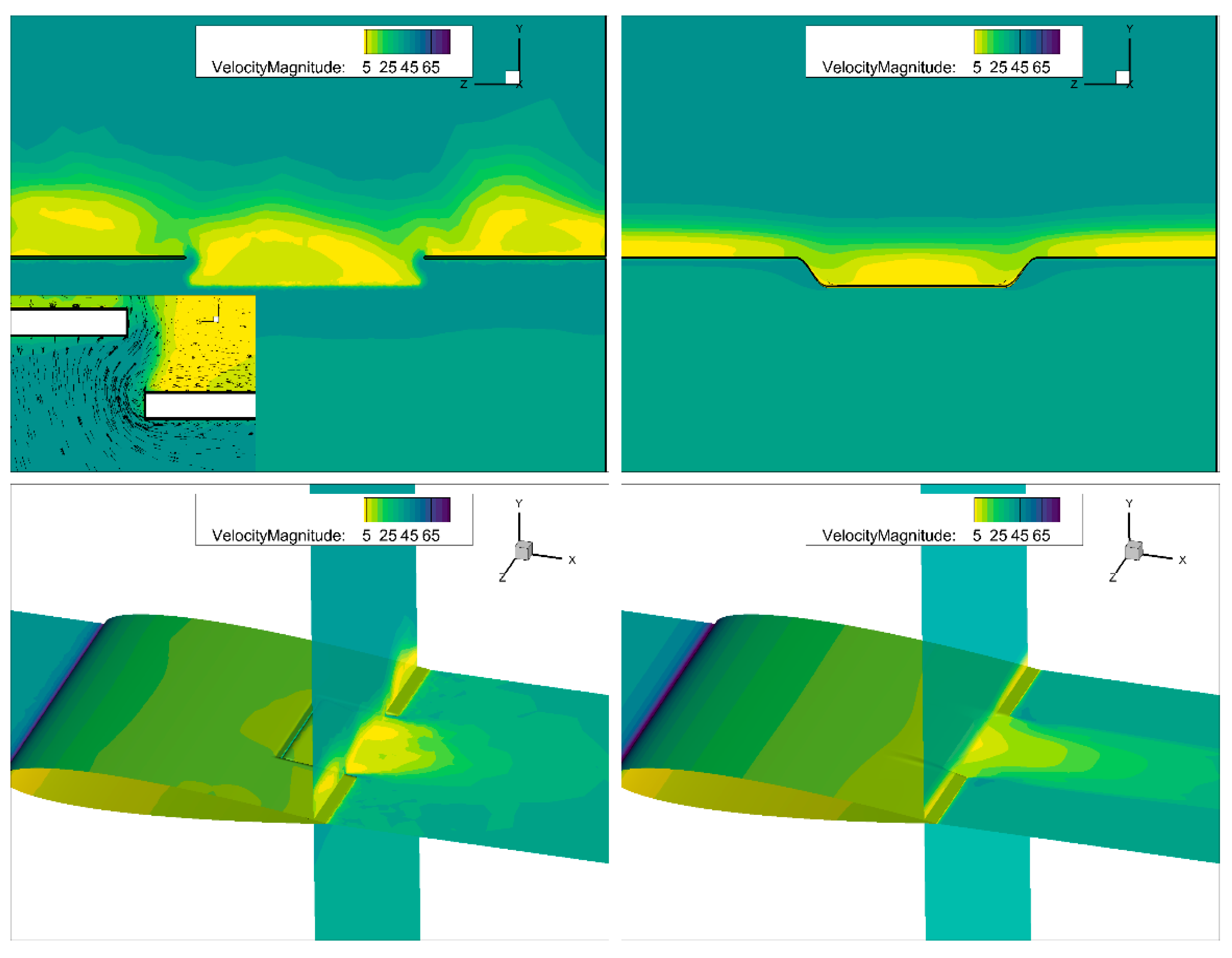
4.2. Statically Morphed TEF vs. Hinged Flap

Figure 7 shows comparative results for CL, CD, and aerodynamic efficiency (CL/CD) for a baseline NACA 0012 wing, a wing equipped with a morphed flap and a wing with a hinged flap, respectively. Table 2 provides individual values for the CL and CD. Comparing the aerodynamic performance of a wing equipped with TEF and a seamless transition and a wing with a traditional hinged TEF gives further insights into their behaviour. When it comes to lift generation, the morphed wing consistently produces an average of a 22% higher lift compared with the hinged flap configuration. The morphed wing also produces a near constant drag reduction of 25% throughout the AoA in the pre-stall, compared with the hinged flap configuration. This results in a consistently higher efficiency for the wing equipped with a morphing flap over a large range of angles of attack, resulting in a maximum of 40% enhanced L/D at AoA = 14°. This result is also consistent with published numerical work, where up to 18% gains in aerodynamic efficiency was achieved for a similar morphing configuration [32] and an over 50% improvement in (L/D) was obtained for a quasi-2D FishBAC experimental study [33].
Another key difference between the morphed and hinged flap configurations is that the wing with a hinged flap experiences the stall at AoA = 12° whereas the morphed flap enters the stall region at AoA = 14°. Compared with the baseline wing configuration, both the hinged flap and the morphed TEF wings produce higher lift and experience earlier stall.
The large difference in the lift between the morphed and hinged flap could be explained by the fact that the morphed wing has two side-edge transition portions deflecting with the flap, creating additional deflection in the camber. This contributes to the extra lift to some extent, whereas the side edges of the hinged flap are static, which does not contribute to lift as much as the seamless transition.
Likewise, those gaps in the hinged flap wing induce large recirculation areas and cavity flows between the gaps while reducing the effective lifting surface. Such effects are particularly significant for the main gap presented between the wing and the flap, which gets larger during the flap deflecting; this may explain the lower aerodynamic efficiency observed for the hinged flap.
Figure 8 illustrates the differences between the wing with a morphed TEF and the seamless transition, and the wing with a hinged flap at three AoAs. Recirculation regions are clearly shown in the velocity contours superimposed with streamlines, and the higher the AoA the larger those regions are. Unlike the wing with the seamless transition, a separation region on the pressure side of the hinged flap seems to be constantly present, growing larger at higher AoAs. In contrast, the velocity field distribution is smoother around the morphed wing. The close-up view in Figure 8 shows the presence of flow leakage through the gaps in the hinged flap configuration with a jet flow emanating from the main gap and increasing in strength with higher AoA.
Figure 9 further illustrates the differences between both configurations. Velocity vectors (top-left figure) clearly demonstrate the effect of the presence of the flap side-edge gaps, side tip vortices are forming at the tips of the flaps and due to the pressure leakage between the suction and pressure sides of the wing, flow is rapidly drawn into the gaps creating a local jet stream flowing towards the suction side. The bottom of Figure 9 shows that the wake flow in the configuration with the hinged flap is more energized and turbulent compared with the morphed wing. The side tip vortices seem to roll up towards the static portion of the wings, triggering more turbulent flow to develop whereas the seamless side-edge transition appears to allow a more gradual and orderly development of the flow, which may contribute to drag reduction observed.
Figure 10 and Figure 11 give more insights into the behaviour of the flow around the configurations studied by investigating the Cp and Cf distributions at the mid-span location (z = 0.5 S) and at x = 0.80 c location (in downstream the flap gap at 0.75c). At the mid-span location, a direct comparison between the FishBAC morphed flap concept and a hinged flap can be made. It can be seen that the difference of Cp is larger around the entire morphed section at all three AoAs, which may explain the extra lift generated compared with the hinged flap case (Figure 7). Two peaks are also noticeable in the pressure distribution of the hinged flap case near the location of the gaps, indicating the presence of the jet flow coming from the pressure side towards the suction side through the gaps. This behaviour could be clearly detected from the Cf plots as well, where the high shear flow is characterized by a peak near the gaps. Differences in Cp distribution are not only presented near the flap region, but also on the main wing where the difference is larger for the wing with a morphed TEF indicating that the perceived camber for the morphed flap is greater from the hinged flap case.
From the Cf plots, sharp peaks associated with the high shear flow due to the jet stream happening near the main gap characterize the distribution of the hinged flap configuration, whereas the transition from the main wing of the morphed flap occurs smoothly. This could be the main reason the wing with a seamless morphed TEF produced an average of 2% less drag.
Figure 11 shows Cp and Cf in the spanwise z-direction at x = 0.8c which is located shortly after the flap starts at x = 0.75c. This graph gives a clear illustration of the differences a sealed seamless transition and an unsealed hinged side-edge flap could produce. The morphed flap Cp distribution is continuous and exhibits an overall similarity in scale and shape between the two configurations with the peaks produced because of the unsealed gaps. The increased contribution of the side-edge seamless transition to the lift is clearly shown for the static side-edge as well.
Finally, when it comes to Cf, a large difference in size is observed, the hinged flap distribution is larger and, overall, more energetic (as exhibited by the oscillation in the Cf distribution). This large difference could be due to the fact that the configuration chosen for this study is a simple flap, not an enclosed flap or a traditional high-lift device. This makes the main gap more influential, triggering the high shear flows over the discrete flap (as clearly observed in the velocity contours of Figure 8) which may contribute to the large drag around the flap and impact on overall loss in the aerodynamic efficiency.

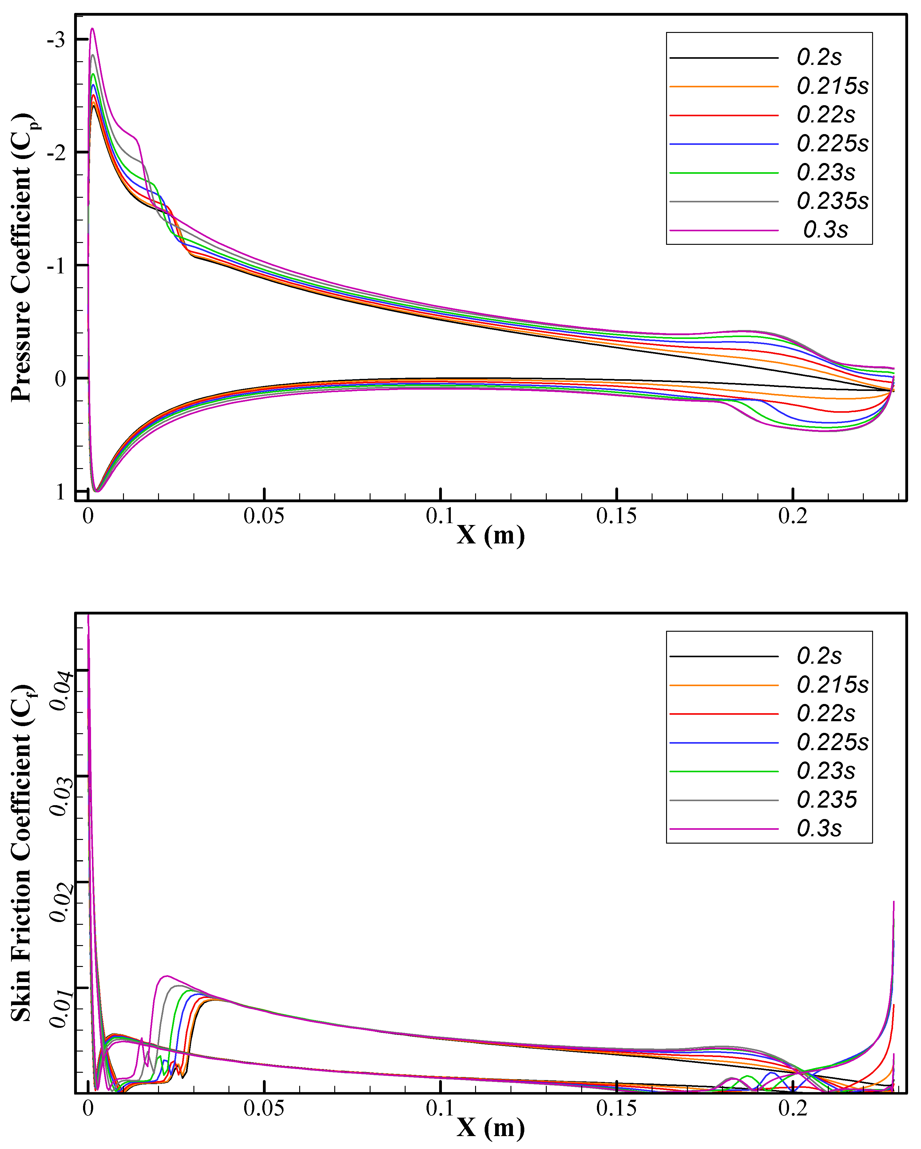
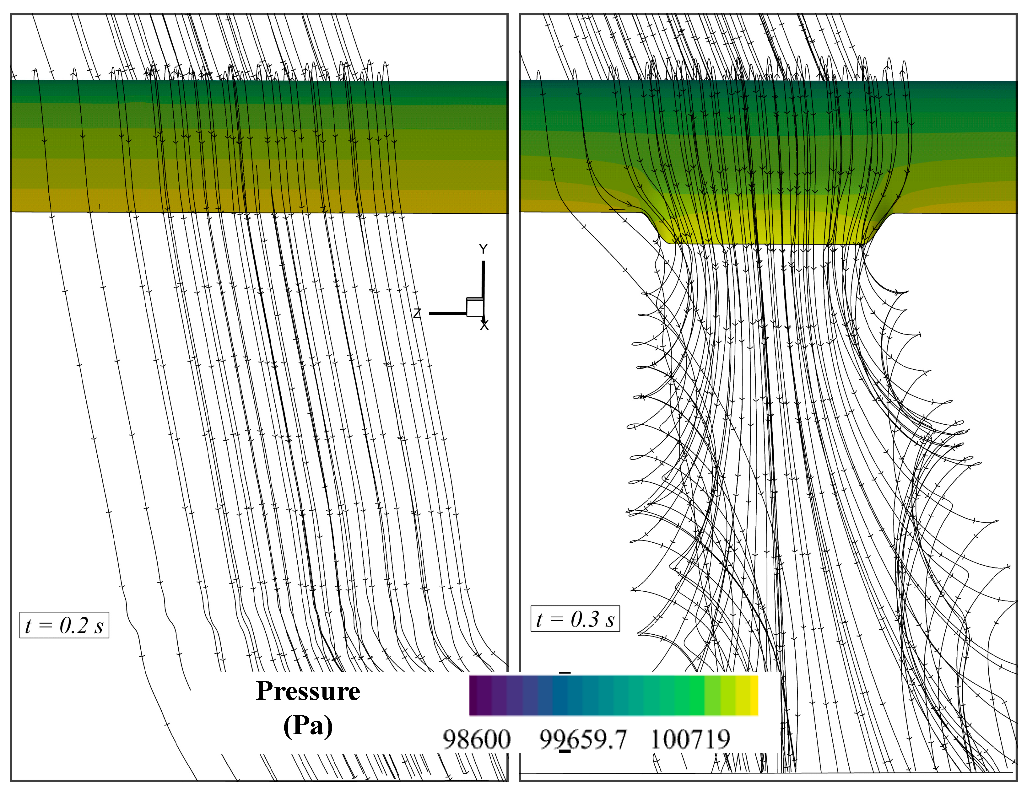
4.3. Unsteady RANS of a Dynamically Morphing TEF

Figure 12 shows the instantaneous CL and CD obtained for the dynamically morphing TEF, for which the dynamic morphing begins at tstart = 0.2 s after the baseline has reached a statically converged state. When the morphing begins, the lift and drag coefficients start increasing in a quasi-linear fashion, similar to those observed in the 2D dynamic morphing [34,53] shows the instantaneous CL and CD obtained for the dynamically morphing TEF, for which the dynamic morphing begins at tstart = 0.2 s after the baseline has reached a statically converged state. When the morphing begins, the lift and drag coefficients start increasing in a quasi-linear fashion, as was observed for the 2D dynamic morphing [34,53].
Throughout the morphing process, small oscillations around the mean value are observed, giving an indication of the presence of a growing vortex shedding. Shortly before the morphing stops, the overshoots in CD observed in previous 2D study [36] is also appeared in present 3D results, with the amplitude of the peak being proportional to the morphing frequency. The highest morphing frequency explored (8 Hz) resulted in a higher peak with an overshoot of 30% compared with the mean value of the coefficient after morphing stops. After the morphing ends, both lift and drag coefficients reach a converged state where small-amplitude oscillations are observed in the coefficient, as can be clearly seen on the embedded figures of Figure 13.
These predictions may be more realistic compared with the statically morphed wing, as in real-life scenarios, the flap is deployed dynamically which gives rise to unsteady flow phenomena (e.g., vortex formation and convection downstream) that could influence the aerodynamic performance, such as the sudden peaks in drag observed before the final TEF position.
For further insights into the unsteady morphing process, instantaneous Cp and Cf distributions at a mid-span (z = 0.5S) and a streamwise location of x = 0.8c are presented in Figure 14 and Figure 15, respectively. These two figures show various instances from the start of the morphing until the end of the morphing. The Cp plots clearly illustrate the effect of the increase in camber has on the pressure distribution. It is clear that the Cp distribution gets larger as the TEF deflection increases which generates more lift. Additionally, instantaneous Cp distribution shows that an incipient Laminar Separation Bubble (LSB) (located initially at 10% of the chord location, i.e., at x = 0.024 m) moves upstream towards the leading edge during the morphing, and settles at the 5% of the chord station (x = 0.013 m) when the flap reaches the maximum morphing deflection prescribed (5% of the chord).
The effects of varying the camber are also present in the Cf distributions. The flow appears to be laminar for the baseline wing at the beginning of morphing, however the more the flap is deflected a clearer transition from laminar to turbulence has been captured, as seen in sudden increase of Cf and the transition location moved upstream with the flap deflection (indicated by time increases from 0.2 s to 0.3 s). The laminar transition to turbulent BL is clearly captured as seen in the sudden increase of Cf, and it appears that the transition gets closer to the LE the more the main flap is deflected, indicating that the transition has some connections with the LSB. A similar conclusion was drawn in a reference paper [37] when the Stress-Blended Eddy Simulation (SBES) model was used along with the intermittency transition modelling. In addition, the transient behaviour of the turbulent separation at the start of the flap is also clearly captured where it appears that with larger deflections the incipient separation point moved more upstream.
The spanwise distribution of Cf (at x = 0.8 c) indicates the presence of a growing recirculation area at the TE with the largest regions presented at the mid-section of the morphing flap. It is worth noting that the distributions of Cp and Cf are mostly symmetrical around the mid-span location.
Further qualitative understanding of this process could be gained by the inspection of the instantaneous velocity and turbulence intensity contours during the morphing process, as illustrated in Figure 16 and Figure 17, respectively. At t = 0.2 s (i.e., the start of the morphing), Figure 16 shows typical behaviour of symmetrical airfoils with a small separation pocket near the TE, this separation bubble grows larger as the flap is gradually morphed, the separation region extends with a more prominent effect on the wake regions. Separation around the flap region becomes larger at t = 0.215 s (Figure 17) where tip vortices start to form around the seamless transition part; this becomes clearer when the TEF reaches its final morphed position. This is clearly illustrated in Figure 18 where the streamlines clearly show the 3D effects induced by the presence of the morphing, seamless side-edge transition. As a consequence of morphing, an elongated separation region is present in the wake region. The effect of tip vortices on the wake is clearly identifiable especially in the turbulence intensity contours (Figure 17) where three regions are identified: a central region related to the flow separation due to the morphing flap, and two side regions resulting from the wakes of the two seamless transitions.
At x = 0.8c, the Cp distribution shows the effects of the seamless side-edge transitions and a gradual increase in the pressure distribution, blending well the Cp values on the morphing flap with the static side edge part. It also shows the massive contribution in lift induced by the downward deflection of the flap.

4.4. Practical Implementation

One of the main strengths of the numerical work produced in this work is the fact that it offers a first look at the fluid dynamics observed in morphing wings with seamless side-edge transition, which otherwise would be hard to replicate in experimental work. Previous works have attempted the study of the dynamic motion of a deflecting flap such as the work by Medina et al. [42], in which a series of experiments to investigate the transient flow responses to low-amplitude high deflection rates of conventional hinged flaps were conducted, however with morphing research, advanced porotypes are needed for experimental investigation which augments the complexity of the problem even for statically deformed configuration. The practical implementation of dynamic morphing would require specific advanced materials needed for the morphed wing (e.g., shape memory alloys or piezoelectric materials), controlled actuation, and, most importantly, experimental setup and associated sensors and equipment that are able to detect transient forces during the morphing process in addition to high-speed cameras. Furthermore, some assumptions were made in this study regarding the operating regime and the morphing frequencies; these should be replicated in an experimental setup for the purpose of fundamental understanding of various flow phenomena, but the latter might be too challenging to replicate in a practical setup which could result in a misalignment of the flow features studied.
Finally, the full set of experimental work might be too expensive to achieve, therefore in order to provide an experimental validation of the current work it is suggested in experimental studies to focus first on the validation of the unsteady lift and drag loads for specific frequency/amplitude pairs at moderate angles of attack. Doing this would provide a robust set of data that can be used for a numerical validation without the extra uncertainties added, for example, at massively separated regime.

5. Conclusion and Future Work

In order to perform the unsteady flow analysis of dynamically morphing TEF with seamless transition, a parametrization method has been modified and implemented in an in-house developed UDF to drive the dynamic mesh in ANSYS Fluent. First, a 3D steady RANS analysis of a statically morphed TEF with seamless transition was performed and the results were compared with both a baseline clean wing and a wing with a traditional hinged flap configuration at a Re = 0.62 × 10⁶ for a range of AoA.
It was found that the baseline NACA 0012 wing produced results comparable with published experimental data and previous numerical work for the NACA 0012 airfoil. Moreover, the morphed wing with the seamless side-edge transition was found to have an average 22% higher lift compared with the hinged flap configuration for a constant drag reduction for the morphed wing of 25% throughout the AoA in pre-stall, resulting in an up to 40% enhancement in aerodynamic efficiency.
Finally, the parametrization method was successfully implemented and unsteady flow analysis at AoA = 6° was performed, offering the possibility to include the deformation motion in the modelling of such morphing configurations. Results for three morphing frequencies of 4 Hz, 6 Hz, and 8 Hz showed that, due to unsteady effects, an overshoot in the drag coefficient was observed for all the configurations studied, which is consistent with the results in published literature.
At the system level, the implication for aircraft with TE morphing flaps will have benefit of ‘net’ specific fuel consumption reduction, giving an enhanced aerodynamic efficiency, but this needs an in-depth system performance analysis which would need to consider the energy expended to operate the actuators. At the design level, this study also demonstrates the need to account for the unsteady effects of morphing motion which could provide large benefits, but at the same time could lead to deterioration at off-design conditions if not taken into account in the preliminary design stages.
In the future, a comparative study between the morphing TEF concept with a seamless side-edge transition and traditional high-lift devices (e.g., 30P30N) will be performed for a better evaluation of their respective performance. Moreover, the developed framework will be used to conduct high fidelity parametric studies of morphing wing configurations at different deflection angles and frequency/magnitude pairs to gain a deeper understanding of how the motion of the flap could affect the flow. Finally, this framework will allow the exploration of 3D harmonic forcing in both the streamwise and spanwise directions. Finally, this 3D morphing concept would be integrated in vertical wind turbine for possible load alleviation purposes and to optimise the energy harvested.

Author Contributions

Conceptualization, C.A., A.B., and Y.Y.; methodology, C.A., A.B., and Y.Y.; software, C.A.; validation, C.A., A.B., and Y.Y.; formal analysis, C.A., A.B., and Y.Y.; investigation, C.A., A.B., and Y.Y.; resources, C.A., A.B., and Y.Y.; data curation, C.A.; writing—original draft preparation, C.A.; writing—review and editing, C.A., A.B., and Y.Y.; visualization, C.A.; supervision, A.B. and Y.Y.; project administration, Y.Y., A.B., and C.A.; funding acquisition, Y.Y., A.B., and C.A. All authors have read and agreed to the published version of the manuscript.

Funding

This research received no external funding.

Institutional Review Board Statement

Not applicable.

Informed Consent Statement

Not applicable.

Data Availability Statement

The data presented in this study are available on request from the corresponding authors.

Acknowledgments

The first author gratefully acknowledges the PhD studentship funding received from the Engineering Modelling and Simulation Research Group, University of the West of England, Bristol, UK. The authors acknowledge the APC funding received from the University of the West of England, Bristol, UK.

Conflicts of Interest

The authors declare no conflict of interest.

Nomenclature

AoAangle of attack, °
cairfoil chord length, m
CDdrag coefficient
CLlift coefficient
CL,maxmaximum lift coefficient
Cfskin friction coefficient
Cppressure coefficient
hhalf-amplitude of the control surface deflection, m
lnon-dimensional spanwise length of morphing portion of transition
Swing span, m
ttime, s
thmaximum airfoil thickness in tenths of chord
Tmorphing period, s
Ufree stream velocity, m/s
wtenon-dimensional maximum vertical Trailing Edge deflection distance
x ¯ non-dimensional distance along the chord
xsnon-dimensional morphing start location
ycnon-dimensional camber line
ytnon-dimensional thickness distribution
z ¯ non-dimensional spanwise transition distribution
ztnon-dimensional vertical TE displacement for the transition part

References

  1. European Commission; Dareki, M.; Edelstenne, C.; Enders, T.; Fernandez, E.; Hartman, P.; Herteman, J.-P.; Kerkloh, M.; King, I.; Ky, P.; et al. Flightpath 2050: Europe’s Vision for Aviation; Publications Office of the European Union: Luxembourg, 2011; Volume 28, ISBN 978-92-79-19724-6. [Google Scholar] [CrossRef]
  2. Gabor, O.S.; Koreanschi, A.; Botez, R.M. A new non-linear vortex lattice method: Applications to wing aerodynamic optimizations. Chin. J. Aeronaut. 2016, 29, 1178–1195. [Google Scholar] [CrossRef] [Green Version]
  3. Abdessemed, C.; Viba, J. Investigation of flight of micro aerial vehicle with flapping wings. Eng. Rural Dev. 2014, 13, 234–240. [Google Scholar]
  4. Osborn, R.F.; Kota, S.; Hetrick, J.A.; Geister, D.E.; Tilmann, C.P.; Joo, J. Active flow control using high-frequency compliant structures. J. Aircr. 2004, 41, 603–609. [Google Scholar] [CrossRef]
  5. Communier, D.; Botez, R.M.; Wong, T. Experimental validation of a new morphing trailing edge system using Price—Païdoussis wind tunnel tests. Chin. J. Aeronaut. 2019, 32, 1353–1366. [Google Scholar] [CrossRef]
  6. Grigorie, T.L.; Khan, S.; Boötes, R.M.; Mamou, M.; Mébarki, Y. Design and experimental testing of a control system for a morphing wing model actuated with miniature BLDC motors. Chin. J. Aeronaut. 2019, 33, 1272–1287. [Google Scholar] [CrossRef]
  7. Weisshaar, T. Morphing aircraft technology-new shapes for aircraft design. Multifunct. Struct./Integr. Sens. Antennas 2006, O1-1–O1-20. [Google Scholar] [CrossRef]
  8. Barbarino, S.; Bilgen, O.; Ajaj, R.M.; Friswell, M.I.; Inman, D.J. A Review of Morphing Aircraft. J. Intell. Mater. Syst. Struct. 2011, 22, 823–877. [Google Scholar] [CrossRef]
  9. Smith, S.B.; Nelson, D.W. Determination of the aerodynamic characteristics of the mission adaptive wing. J. Aircr. 1990, 27, 950–958. [Google Scholar] [CrossRef]
  10. Moens, F. Augmented aircraft performance with the use of morphing technology for a turboprop regional aircraft wing. Biomimetics 2019, 4, 64. [Google Scholar] [CrossRef] [Green Version]
  11. Arena, M.; Palumbo, R.; Pecora, R.; Amoroso, F.; Amendola, G.; Dimino, I. Flutter clearance investigation of camber-morphing aileron tailored for a regional aircraft. J. Aerosp. Eng. 2019, 32, 4018146. [Google Scholar] [CrossRef]
  12. Jianyang, Z.; Lin, J.; Yu, H. Aerodynamic performance of the three-dimensional lumped flexibility bionic hovering wing. Int. J. Aerosp. Eng. 2018, 2018, 1314258. [Google Scholar] [CrossRef]
  13. Arena, M.; Concilio, A.; Pecora, R. Aero-servo-elastic design of a morphing wing trailing edge system for enhanced cruise performance. Aerosp. Sci. Technol. 2019, 86, 215–235. [Google Scholar] [CrossRef]
  14. Bowers, A.H.; Murillo, O.J.; Jensen, R.R.; Eslinger, B.; Gelzer, C. On Wings of the Minimum Induced Drag: Spanload Implications for Aircraft and Birds; NASA: Washington, DC, USA, 2016.
  15. Nguyen, N. Project Elastically Shaped Future Air Vehicle Concept. NASA Innovation Fund Award 2010. Available online: https://www.nasa.gov/pdf/499930main_arc_nguyen_elastically_shaped.pdf (accessed on 14 November 2021).
  16. Urnes, J.; Nguyen, N. A Mission Adaptive Variable Camber Flap Control System to Optimize High Lift and Cruise Lift to Drag Ratios of Future N+3 Transport Aircraft. In Proceedings of the 51st AIAA Aerospace Sciences Meeting including the New Horizons Forum and Aerospace Exposition (AIAA-2013-214), Grapevine, TX, USA, 7–10 January 2013; pp. 1–24. [Google Scholar] [CrossRef] [Green Version]
  17. Daochun, L.; Shijun, G.; Osman, A.T.; Daqing, Y.; Jinwu, X. Active control design for an unmanned air vehicle with a morphing wing. Aircr. Eng. Aerosp. Technol. Int. J. 2016, 88, 168–177. [Google Scholar] [CrossRef]
  18. Macaraeg, M. Fundamental investigations of airframe noise. In Proceedings of the 4th AIAA/CEAS Aeroacoustics Conference, Toulouse, France, 2–4 June 1998; American Institute of Aeronautics and Astronautics: Toulouse, France, 1998; pp. 123–132. [Google Scholar] [CrossRef] [Green Version]
  19. Daynes, S.; Weaver, P.M. A morphing trailing edge device for a wind turbine. J. Intell. Mater. Syst. Struct. 2012, 23, 691–701. [Google Scholar] [CrossRef]
  20. Pisetta, G.; Le Mestre, R.; Viola, I.M. Morphing blades for tidal turbines: A theoretical study. Renew. Energy 2022, 183, 802–819. [Google Scholar] [CrossRef]
  21. Khorrami, M.R.; Lockard, D.P.; Moore, J.B.; Su, J.; Turner, T.L.; Lin, J.C.; Taminger, K.M.; Kahng, S.K.; Verden, S.A. Elastically Deformable Side-Edge Link for Trailing-Edge Flap Aeroacoustic Noise Reduction. US20120153086A1, 15 April 2014. [Google Scholar]
  22. Kota, S.; Osborn, R.; Ervin, G.; Maric, D.; Flick, P.; Paul, D. Mission adaptive compliant wing–design, fabrication and flight test. In Proceedings of the RTO Applied Vehicle Technology Panel (AVT) Symposium, Evora, Portugal, 20–24 April 2009. [Google Scholar]
  23. Kota, S.; Flick, P.; Collier, F.S. Flight Testing of FlexFloil TM Adaptive Compliant Trailing Edge. In Proceedings of the 54th AIAA Aerospace Sciences Meeting, San Diego, CA, USA, 4–8 January 2016; pp. 1–13. [Google Scholar] [CrossRef]
  24. NASA. Hear This: 30 Percent Less Noise. Available online: https://www.nasa.gov/centers/armstrong/feature/ACTE_30_percent_less_noise.html (accessed on 13 April 2017).
  25. Woods, B.K.S.; Parsons, L.; Coles, A.B.; Fincham, J.H.S.; Friswell, M.I. Morphing elastically lofted transition for active camber control surfaces. Aerosp. Sci. Technol. 2016, 55, 439–448. [Google Scholar] [CrossRef] [Green Version]
  26. Woods, B.K.S.; Friswell, M.I. Preliminary investigation of a fishbone active camber concept. In Proceedings of the ASME 2012 Conference on Smart Materials, Adaptive Structures and Intelligent Systems, Stone Mountain, GA, USA, 19–21 September 2012; pp. 555–563. [Google Scholar]
  27. Molinari, G.; Quack, M.; Dmitriev, V.; Morari, M.; Jenny, P.; Ermanni, P. Aero-Structural Optimization of Morphing Airfoils for Adaptive Wings. J. Intell. Mater. Syst. Struct. 2011, 22, 1075–1089. [Google Scholar] [CrossRef]
  28. Obradovic, B.; Subbarao, K. Modeling and Simulation of Morphing Wing Aircraft. In Morphing Aerospace Vehicles and Structures; Valasek, J., Ed.; John Wiley & Sons, Inc.: Hoboken, NJ, USA, 2012; Volume 48, pp. 87–125. [Google Scholar] [CrossRef]
  29. Koreanschi, A.; Gabor, O.S.; Acotto, J.; Brianchon, G.; Portier, G.; Botez, R.M.; Mamou, M.; Mebarki, Y. Optimization and design of an aircraft’s morphing wing-tip demonstrator for drag reduction at low speed, Part I—Aerodynamic optimization using genetic, bee colony and gradient descent algorithms. Chin. J. Aeronaut. 2017, 30, 149–163. [Google Scholar] [CrossRef]
  30. Lyu, Z.; Martins, J.R.R.A. Aerodynamic Shape Optimization of an Adaptive Morphing Trailing-Edge Wing. J. Aircr. 2015, 52, 1951–1970. [Google Scholar] [CrossRef] [Green Version]
  31. Jawahar, H.K.; Ai, Q.; Azarpeyvand, M. Experimental and Numerical Investigation of Aerodynamic Performance of Airfoils Fitted with Morphing Trailing-edges. In Proceedings of the 23rd AIAA/CEAS Aeroacoustics Conference, Denver, CO, USA, 5–9 June 2017; American Institute of Aeronautics and Astronautics: Reston, VA, USA, 2017. [Google Scholar] [CrossRef] [Green Version]
  32. Ninian, D.; Dakka, S. Design, Development and Testing of Shape Shifting Wing Model. Aerospace 2017, 4, 52. [Google Scholar] [CrossRef] [Green Version]
  33. Rivero, A.E.; Fournier, S.; Manolesos, M.; Cooper, J.E.; Woods, B.K.S. Experimental Aerodynamic Comparison of Active Camber Morphing and Trailing-Edge Flaps. AIAA J. 2021, 59, 2627–2640. [Google Scholar] [CrossRef]
  34. Abdessemed, C.; Yao, Y.; Bouferrouk, A.; Narayan, P. Morphing airfoils unsteady flow analysis using dynamic meshing. Int. J. Numer. Methods Heat Fluid Flow 2018, 28, 1117–1133. [Google Scholar] [CrossRef] [Green Version]
  35. Abdessemed, C.; Yao, Y.; Narayan, P.; Bouferrouk, A. Unsteady parametrization of a morphing wing design for improved aerodynamic performance. In Proceedings of the 52rd 3AF International Conference on Applied Aerodynamics, Lyon, France, 27–29 March 2017; pp. 1–10. [Google Scholar]
  36. Abdessemed, C.; Yao, Y.; Bouferrouk, A.; Narayan, P. Flow Response to Rapid Morphing Flap Deflection. In Proceedings of the 54th 3AF International Conference on Applied Aerodynamics, Paris, France, 25–27 March 2019; pp. 1–10. [Google Scholar]
  37. Abdessemed, C.; Yao, Y.; Bouferrouk, A. Near Stall Unsteady Flow Responses to Morphing Flap Deflections. Fluids 2021, 6, 180. [Google Scholar] [CrossRef]
  38. Abdessemed, C.; Bouferrouk, A.; Yao, Y. Aerodynamic and Aeroacoustic Analysis of a Harmonically Morphing Airfoil Using Dynamic Meshing. Acoustics 2021, 3, 177–199. [Google Scholar] [CrossRef]
  39. ANSYS Release 18.2, Help System; Ansys: Canonsburg, PA, USA, 2018.
  40. Abdessemed, C. Dynamic Mesh Framework for Morphing Wings CFD—User Defined Function. 2020. Available online: https://doi.org/10.5281/zenodo.3724146(accessed on 3 April 2020).
  41. Abdessemed, C.; Yao, Y.; Bouferrouk, A.; Narayan, P. Analysis of a 3D Unsteady Morphing Wing with Seamless Side-edge Transition. In Proceedings of the 2018 Applied Aerodynamics Conference, Atlanta, GA, USA, 25–29 June 2018; p. 2897416. [Google Scholar] [CrossRef] [Green Version]
  42. Medina, A.; Hemati, M.S.; Rockwood, M. Separated flow response to rapid flap deflection. AIAA J. 2020, 58, 1446–1457. [Google Scholar] [CrossRef]
  43. Abdessemed, C. Dynamic Mesh Framework for Morphing Wings CFD. Ph.D. Thesis, University of the West of England, Bristol, UK, 2019. [Google Scholar]
  44. Woods, B.K.S.; Fincham, J.H.S.; Friswell, M.I. Aerodynamic Modelling of the Fish Bone Active Camber Morphing Concept. In Proceedings of the RAeS Applied Aerodynamics Conference, Bristol, UK, 22–24 July 2014; Volume 25, pp. 772–785. [Google Scholar] [CrossRef]
  45. Holst, D.; Church, B.; Pechlivanoglou, G.; Tüzüner, E.; Saverin, J.; Nayeri, C.N.; Paschereit, C.O. Experimental Analysis of a NACA 0021 Airfoil Section Through 180-Degree Angle of Attack at Low Reynolds Numbers for Use in Wind Turbine Analysis. In Proceedings of the ASME Turbo Expo 2017: Turbomachinery Technical Conference and Exposition, Charlotte, NC, USA, 26–30 June 2017. [Google Scholar] [CrossRef]
  46. Sheldahl, R.E.; Klimas, P.C. Aerodynamic characteristics of seven symmetrical airfoil sections through 180-degree angle of attack for use in aerodynamic analysis of vertical axis wind turbines. Chem. Amp. 1981, SAND80-211, 118. [Google Scholar] [CrossRef] [Green Version]
  47. Menter, F.R. Best Practice: Scale-Resolving Simulations in ANSYS CFD; Ansys: Canonsburg, PA, USA, 2012; pp. 1–70. [Google Scholar] [CrossRef]
  48. Spalart, P.R.; Deck, S.; Shur, M.L.; Squires, K.D.; Strelets, M.K.; Travin, A. A new version of detached-eddy simulation, resistant to ambiguous grid densities. Theor. Comput. Fluid Dyn. 2006, 20, 181–195. [Google Scholar] [CrossRef]
  49. Abdessemed, C.; Yao, Y.; Bouferrouk, A.; Narayan, P. Influence of non-iterative time-advancement schemes on the aerodynamic prediction of pitching airfoils using dynamic mesh. In Proceedings of the 8th International Symposium on Physics of Fluids (ISPF8), Xi’an, China, 10–13 June 2019. [Google Scholar]
  50. Jain, S.; Sitaram, N.; Krishnaswamy, S. Effect of Reynolds Number on Aerodynamics of Airfoil with Gurney Flap. Int. J. Rotating Mach. 2015, 2015, 628632. [Google Scholar] [CrossRef] [Green Version]
  51. Abe, K.; Kondoh, T.; Nagano, Y. A new turbulence model for predicting fluid flow and heat transfer in separating and reattaching flows—I. Flow field calculations. Int. J. Heat Mass Transf. 1994, 37, 139–151. [Google Scholar] [CrossRef]
  52. Arko, B.M.; McQuilling, M. Computational study of high-lift low-pressure turbine cascade aerodynamics at low reynolds number. J. Propuls. Power 2013, 29, 446–459. [Google Scholar] [CrossRef]
  53. Abdessemed, C.; Yao, Y.; Bouferrouk, A.A.; Narayan, P. Aeroacoustic Investigation of a Harmonically Morphing Trailing Edge Flap. In Proceedings of the 53rd 3AF International Conference on Applied Aerodynamics, Salon de Provence, France, 26–28 March 2018; pp. 23–26. [Google Scholar]
Figure 1. Illustration showing the dynamic morphing process driven by the modified unsteady parametrization method.
Energies 15 01093 g001
Figure 2. Mid-span slices showing the configurations studied and their dimensions.
Energies 15 01093 g002
Figure 3. 3D models of the statically morphed wing and the hinged flap wing from various views.
Energies 15 01093 g003
Figure 4. Computational domains used studies with close-up of the baseline NACA0012 win and hinged flap wing.
Energies 15 01093 g004
Figure 5. Direct comparison between the baseline un-deformed mesh (upper) and the mesh after the TEF deformation (lower).
Energies 15 01093 g005
Figure 6. CL and CD results for the baseline NACA 0012 wing compared with numerical results obtained for the NACA 0012 airfoil from Sheldahl et al. [46].
Energies 15 01093 g006
Figure 7. Comparative results for CL and CD and the aerodynamic efficiency (CL/CD) for the baseline NACA 0012 wing, the wing equipped with a morphed flap and the one with a hinged flap in addition to the 2D prediction of an airfoil with a morphed TEF.
Energies 15 01093 g007
Figure 8. Velocity contours comparison at mid-span between the wing with the hinged and a morphed TEF at AoA = 6°, 8° and 13°. The close-ups show the side view at mid-span for both configurations.
Energies 15 01093 g008
Figure 9. Top: Velocity contours and vectors of the wing with a morphed TEF flap (top right) compared with the one with a hinged flap (top left) on a plane placed at x = 0.99c at AoA = 13°. Bottom: wake flow structure visualisation by means of velocity contours with a slice at y = 0 and x = 0.95c.
Energies 15 01093 g009
Figure 10. Cp and Cf comparison between the wing with a morphing TEF and seamless transition and the wing with a hinged flap, mid-span location at AoA = 6°, 8° and 13° from top to bottom.
Energies 15 01093 g010
Figure 11. Cp and Cf comparison between the wing with a morphing TEF and seamless transition and the wing with a hinged flap, x = 0.8c location at AoA = 6°, 8° and 13° from top to bottom.
Energies 15 01093 g011
Figure 12. Visualization of flow separation by means of velocity contours with a slice at y = 0 and x = 0.95c comparing the wing with a morphing TEF and seamless transition (bottom) and the wing with a hinged flap (top).
Energies 15 01093 g012
Figure 13. Time history of CL and CD for the dynamically morphing TEF of the wing with side transition at AoA = 6° for three morphing frequencies.
Energies 15 01093 g013
Figure 14. Instantaneous Cp (top) and Cf (bottom) distributions for the dynamically morphing TEF at AoA = 6° at a mid-span slice (z = 0.5S).
Energies 15 01093 g014
Figure 15. Instantaneous Cp (top) and Cf (bottom) for the dynamically morphing TEF at AoA = 6° on a slice at x = 0.8c.
Energies 15 01093 g015
Figure 16. Instantaneous velocity contours placed at three stations at six time instances illustrating the dynamic morphing process of a 3D wing with seamless side-edge transitions at AoA = 6° and a morphing frequency of 8 Hz.
Energies 15 01093 g016
Figure 17. Instantaneous turbulent intensity contours placed at three stations and six time instances illustrating the dynamic morphing process of a 3D wing with seamless side-edge transitions at AoA = 6° and a morphing frequency of 8 Hz.
Energies 15 01093 g017
Figure 18. Streamlines and surface pressure contours illustrating the 3D effect induced by the dynamic morphing process of a 3D wing with seamless side-edge transitions, in comparison to a baseline configuration, before morphing starts (AoA = 6°, morphing frequency = 8 Hz).
Energies 15 01093 g018
Table 1. Comparative table of numerical results for CL and CD coefficient compared with experiment.
AOACLCD
FluentExpDeltas (%)FluentExpDeltas (%)
40.4480.4294.3370.0080.0087.735
60.6800.6465.0140.0120.01010.700
80.8570.8243.8330.0130.0134.923
100.9960.9930.3610.0190.01616.084
121.1371.1181.7030.0260.02121.076
131.1711.1293.5630.0320.0298.849
141.1321.0774.9000.0440.0416.204
Average 3.38 10.79
Table 2. Comparative table of numerical results for CL and CD coefficient for the studied configurations; baseline NACA0012, hinged flap and morphed flap.
AoACLCD
NACA0012Hinged FlapMorphed FlapNACA0012FlappedMorphed
40.4480.5540.7330.0080.0210.018
60.6800.7390.9100.0120.0260.023
80.8570.9031.0820.0130.0320.027
100.9961.0541.2450.0190.0420.032
121.1371.1481.3920.0260.0550.040
131.1711.0931.4470.0320.0760.047
141.1320.7881.4810.0440.1490.054
Publisher’s Note: MDPI stays neutral with regard to jurisdictional claims in published maps and institutional affiliations.

