Article

A Study on a Design Considering the Transient State of a Line-Start Permanent Magnet Synchronous Motor Satisfying the Requirements of the IE4 Efficiency Class

1
Department of Electrical Engineering, Hanyang University, Seoul 04763, Republic of Korea
2
Intelligent Mechatronics Research Center, Korea Electronics Technology Institute, Bucheon-si 14502, Republic of Korea
*
Author to whom correspondence should be addressed.
Energies 2022, 15(24), 9644; https://doi.org/10.3390/en15249644
Submission received: 11 November 2022 / Revised: 12 December 2022 / Accepted: 15 December 2022 / Published: 19 December 2022
(This article belongs to the Special Issue Regulations and Advances in High Performance Electric Motor and Drive)

Abstract

:
In this paper, the transient state analysis of a Line-Start Permanent Magnet Synchronous Motor (LSPMSM) and the optimum design for high efficiency were studied. In the case of an LSPMSM, aluminum bars and permanent magnets are inserted in the rotor. Since it has aluminum bars, it can be directly started on-line without closed-loop control at the time of starting, like an induction motor. Furthermore, once driven, it rotates at a synchronous speed due to the permanent magnets in the steady state. Theoretically, since the rotor bars have no induced current, copper loss does not occur in the rotor bars. Further, because of the inserted permanent magnets, an LSPMSM has a higher power density than an induction motor with the same output power. However, since it is driven directly on-line, the transient state is longer than that of a synchronous motor driven by an inverter. Therefore, it is important to analyze the characteristics of the transient state depending on the rotor shape in the LSPMSM design. In this study, an LSPMSM that has the same outer diameter of a 7.5 kW IE3 efficiency class induction motor currently used for the industry was designed. The optimal design of the motor was designed using Finite-Element Analysis (FEA) and Design of Experiment (D.O.E). In the design process, the velocity ripple was minimized in the transient state, and the steady state was quickly reached. Finally, the efficiency of the motor satisfies the requirements of the IE4 efficiency class, an efficiency standard described in IEC 60034-30, which is an international standard.

1. Introduction

Recently, awareness of the crisis of environmental problems and the limits of energy resources has been gradually increasing. Furthermore, almost all developed countries have implemented policies for carbon neutrality. In the field of automobiles, various attempts are being made, such as replacing the existing internal combustion engine with an electric motor for electric vehicles. Furthermore, in the field of construction machinery, an electric cylinder has been replacing the existing hydraulic cylinder. In addition, the Minimum Energy Performance Standard (MEPS) policy is implemented for the popularization of high-efficiency motors that could reduce green gas and save energy [1]. Efficiency standards are being gradually made stricter. More than 54% of the total energy is used in industrial induction motors, and in general, the lifespan of induction motors is 15 years or more. Therefore, it is important to increase the efficiency of the induction motor. According to IEC 60034-30, the efficiency standard of a motor is defined, and Figure 1 shows the efficiency of IE1 and IE4. IE1 and IE4 are defined as standard efficiency and super premium efficiency, respectively. Furthermore, the IE4 efficiency class requires about 5% higher efficiency than IE1 regardless of output. Specifically, the efficiency of the IE4 class for a 7.5 kW motor is 92.6% [2,3,4,5].
In driving a general synchronous motor, an inverter for generating the desired AC output and a position sensor and current sensors for generating an accurate sinusoidal current according to the rotor position are required. However, unlike general synchronous motors, LSPMSMs do not require an inverter or sensors and are synchronous motors that can be driven directly on-line [6,7,8,9]. Additionally, LSPMSMs have aluminum bars inserted into the rotor in addition to permanent magnets. Therefore, when the motor is initially started, induced currents are generated in the rotor bars by the rotating magnetic field from the stator. The induced currents make it possible to drive the motor even when the rotor speed is asynchronous. This is the same as the principle of an induction motor. However, in the steady state, it is driven at synchronous speed by the permanent magnets of the rotor, which is different from the induction motor operating at asynchronous speed [10,11,12,13,14,15,16]. The design of the LSPMSM has been researched [15,16,17], and LSPMSMs are currently mass-produced in some advanced companies, such as WEG and SEW, to replace induction motors due to the regulation of IE4 class efficiency. Furthermore, LSPMSMs with 4 and 6 poles of 7.5 kW or less are mainly produced. Two-pole motors with less than 7.5 kW and motors with more than 7.5 kW have not yet been commercialized because IE4 class induction motors could be produced through the efficiency improvement technology of the existing IE3 class induction motor.
In this study, an LSPMSM was design for satisfying IE4 class efficiency. Meanwhile, rare earth magnets (neodymium) were selected as the permanent magnet of the LSPMSM. However, there is not much price difference compared to induction motors since the stack length, die-casting and coil length can be reduced. In addition, it has the advantage of not having to use advanced die-casting technology for manufacturing IE4 class induction motors. Furthermore, it has the same size as the outer diameter of the case of the 7.5 kW IE3 efficiency class induction motor currently used in the industrial field. In addition, the optimal design was discovered using FEA and DOE to maintain the outermost size of the induction motor. First, in the case of LSPM in this paper, since the frame of the conventional induction motor is used, the outer diameter of the stator and the outer diameter of the rotor are determined, and the stacking is calculated using the sizing method. Second, the shape of the rotor aluminum bar is determined based on the NEMA class. Third, Finite-Element Analysis (FEA) and Design of Experiment (D.O.E) are used to analyze the transient state of LSPM, and the final model is determined using the optimum design. Fourth, the performance of the manufactured motor based on the final model verified by the experiment to see if the designed efficiency was achieved.

2. Structure and Characteristic of LSPM

Figure 2 shows the rotor of a four-pole LSPMSM. The rotor of LSPMSM has four permanent magnets and aluminum bars on the rotor. Therefore, it can be started directly on-line without an inverter. Figure 2 shows the d-axis and q-axis of a four-pole LSPM. The d-axis means the main magnetic flux axis by the permanent magnet, and the q-axis means the axis 90 electrical degrees ahead of the d-axis. For the d-axis in Figure 2, there are permanent magnets and rotor slot aluminum, a magnetic air gap and a mechanical air gap, so the equivalent air gap is large, and the d-axis inductance ( L d ) is minimal. However, along the q-axis, the equivalent air gap along the q-axis includes only the mechanical air gap, so the q-axis inductance ( L q ) is maximized. Therefore, in the case of LSPMSM, it has a reverse saliency ( L q > L d ) similar to an Interior Permanent Magnet Synchronous Motor (IPMSM). Therefore, when operating in a steady state, the LSPMSM operates like an IPMSM and thus has the characteristics of an IPMSM with high power density.

3. Design of the LSPMSM

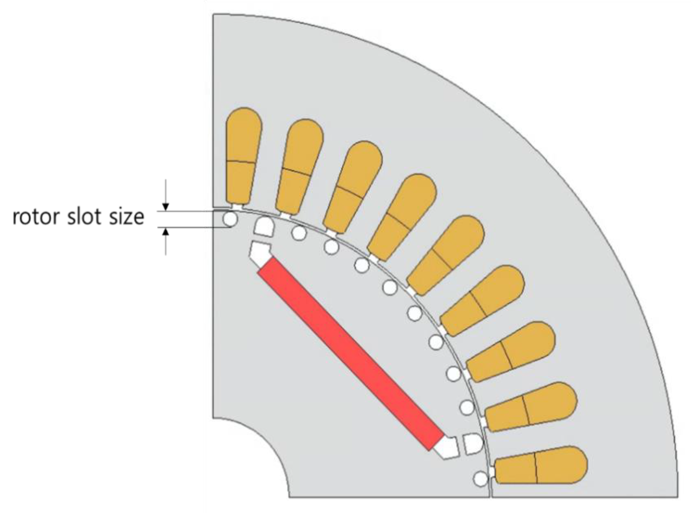
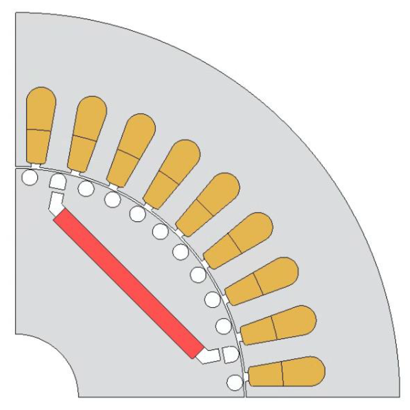
3.1. Determination of the Motor Size and Rotor Slot Shape

In this paper, the stator and frame of the motor are made to have the same shape as the 7.5 kW induction motor used in the industry. Therefore, it can improve the manufacturability and reduce the manufacturing cost. It can also easily replace an induction motor at any time. Since the size of the stator and rotor is determined by the induction motor, only the stack length was selected for satisfying the 7.5 kW output power. Therefore, it can be selected to 170 mm, and the detailed specifications of the motor is shown in Table 1.
Figure 3 shows the four rotor bar shapes according to the NEMA design standard, and Figure 4 shows the speed–torque characteristic curves for each shape [18,19]. Classes A and B have relatively low initial driving torque and drive with a slip of up to 5%. In the case of class B, the maximum locked rotor torque is slightly lower than that of class A, and it is the most widely used for induction motors. In the case of the C class, it has a medium initial driving torque and is driven with a slip of up to 5%. Furthermore, the efficiency of class C is lower than that of classes A and B. Class D has the highest locked rotor torque and operates with a slip of 5–8%. Furthermore, the efficiency of class D is the lowest among the four classes. However, since LSPSM drives at a synchronous speed in the steady state and has no copper loss, it is not important to consider efficiency in the NEMA standard. In addition, since the permanent magnet in the rotor of the LSMPSM generates a braking torque during initial operation, a large driving torque is required to overcome that torque. Therefore, Class D is the most appropriate for the design of the LSPMSM, considering the insertion space of the permanent magnet as well as the largest torque in the initial drive.
After determining the shape of the rotor bar, the number of rotor bars must be determined. In the case of rotor bars, it is advisable to use a successful combination of slots to avoid parasitic torque, noise, vibration, etc. [20,21]. Table 2 shows commonly used rotor bar combinations depending on the number of poles and stator slots. Meanwhile, it is not possible to verify the slot combination each time a motor is designed, so it is desirable to choose a successful slot combination using empirical knowledge. Therefore, we chose 48 rotor bars based on the recommended combination.

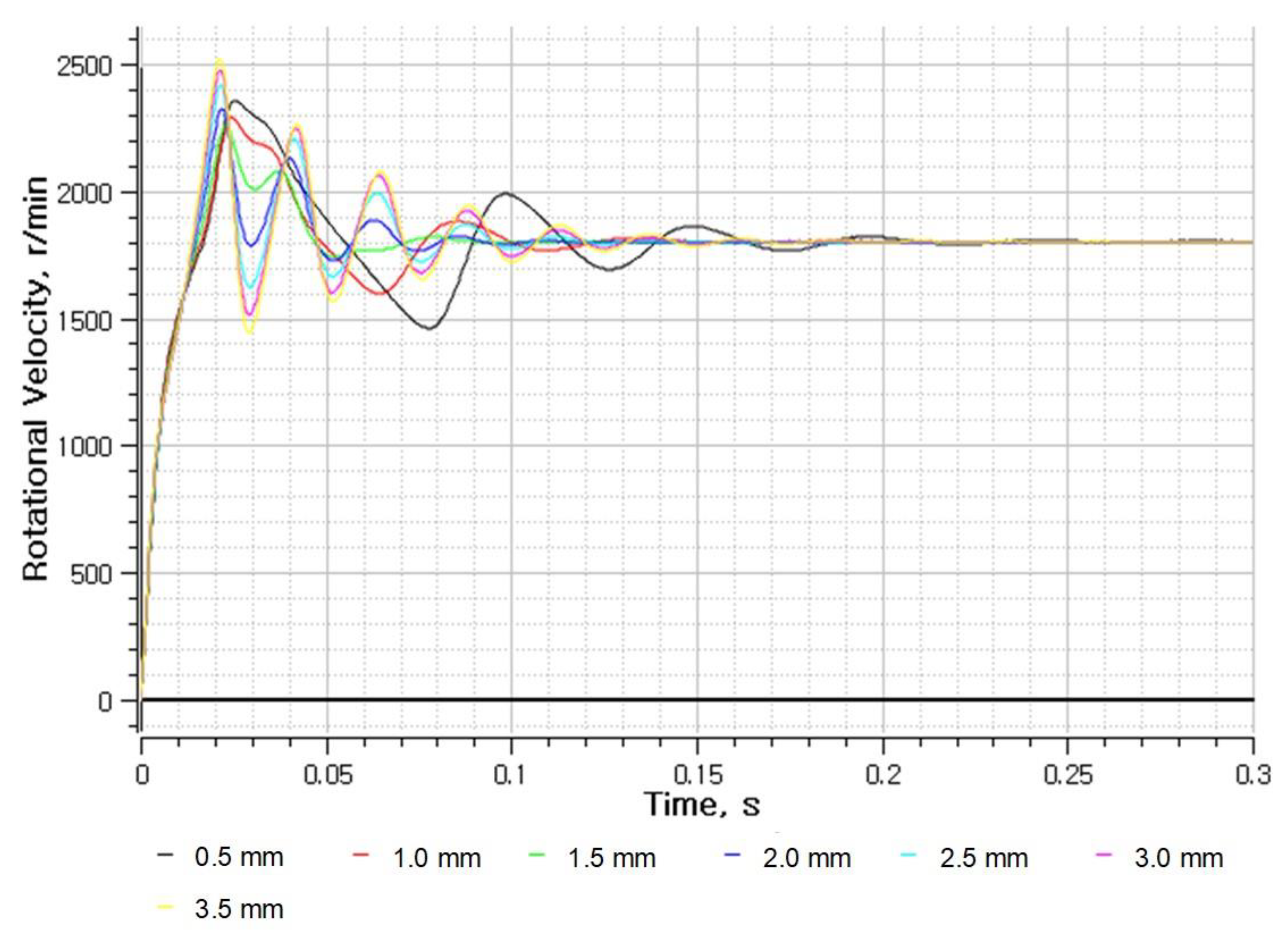
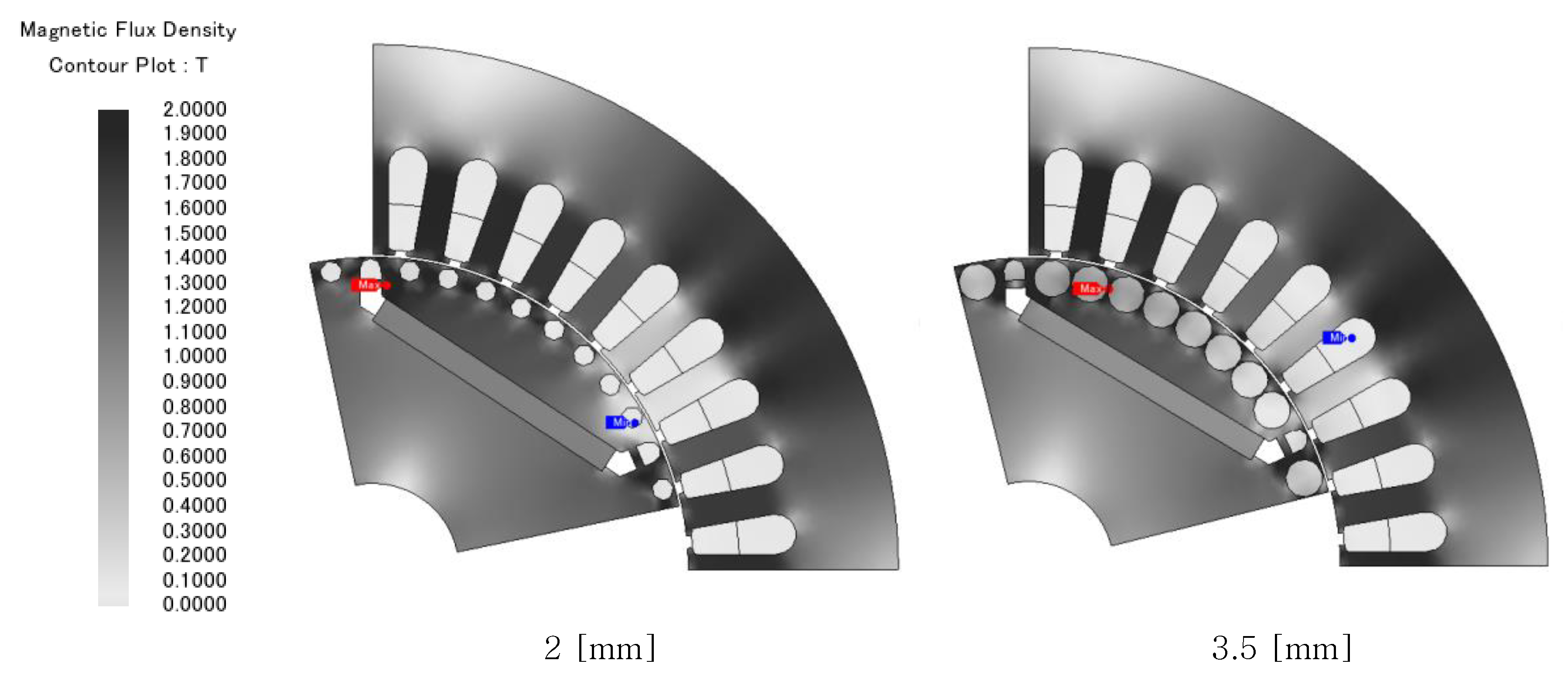
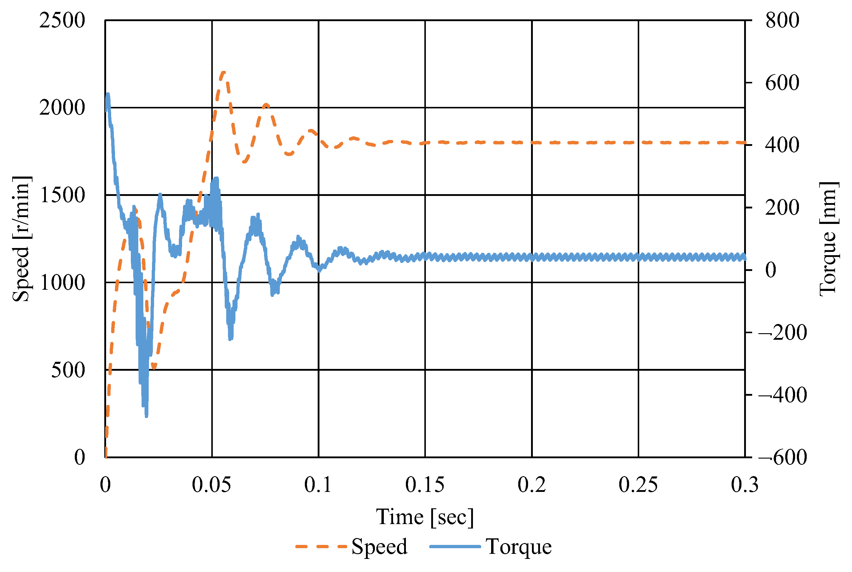
3.2. Design of Rotor Slot Considering Transient State Using FEA

In this section, in order to analyze the initial characteristics of the LSPMSM, motor performance in the transient state was analyzed using FEA depending on the rotor bar size. Figure 5 shows a 1/4 model of LSPMSM, wherein the size of the rotor bar varied from 0.5 to 3.5 mm. In addition, FEA analysis was performed for two cases when inertia was set to the default value (0.022 kg·m2/s) and when inertia was set to 30 times the default value.
Figure 6 and Table 3 show the FEA results when inertia is set as the default value. Figure 6 shows the motor speed in the time domain depending on the size of the rotor bars in the transient state, and Table 3 shows the motor performance in a steady state.
In Figure 6, when the bar size is 0.5, it is shown that the velocity ripple is large and that the convergence rate is relatively slow. Furthermore, in Table 3, when the bar size is 2.5 or more, the current increases to 30 Arms or more. Furthermore, the efficiency becomes less than 90% and does not satisfy the requirements of the IE4 efficiency class. Therefore, it is appropriate to select bar sizes of 1, 1.5, and 2 when inertia is the default value.
In Figure 7, when the bar size is smaller than 2, the steady-state speed does not reach the rated 1800 RPM. Furthermore, Table 3 shows that the current is large and that the efficiency is low in the steady state except for a bar size of 2. Therefore, it can be confirmed that 2 is the optimal value for the bar size according to the FEA analysis result.
When the diameter of the rotor bars of an induction motor increases, the resistance of the rotor bar ( r 2 ) decreases. The starting torque increases as shown in Equation (1) of the torque equation for an induction motor, and the settling time for steady state would be shortened [22].
T = P 2 ω s = P 4 π f m V 2 r 2 / s ( r 1 + r 2 / s ) 2 + ( x 1 + x 2 ) [ N m ] ,
where P 2 is the rotor input, ω s is the slip speed, s is slip, m is the number of the phase, r 1 is the stator resistance, and x 1 ,   x 2 are the reactance of the stator and rotor bar, respectively. Furthermore, looking at Table 4, it can be confirmed that the efficiency decreases as the bar size increases in the range of 2.5 to 3.5 mm. The reason is that, as the size of the bar increases, the saturation of the rotor increases, as shown in Figure 8, and the magnetic flux of the permanent magnet cannot flow to the stator side, and more current is required to generate the same torque. As a result, copper loss increases and efficiency decreases. Therefore, there is a trade-off relationship between efficiency and transient state characteristics, and if the bar size is unconditionally increased to improve the transition state characteristics, a large amount of current will flow and efficiency will drop, so an appropriate bar size must be selected. Therefore, we selected a bar size of 2 mm, which starts with a bar maximum inertia of 30 times and has a high efficiency and power factor.

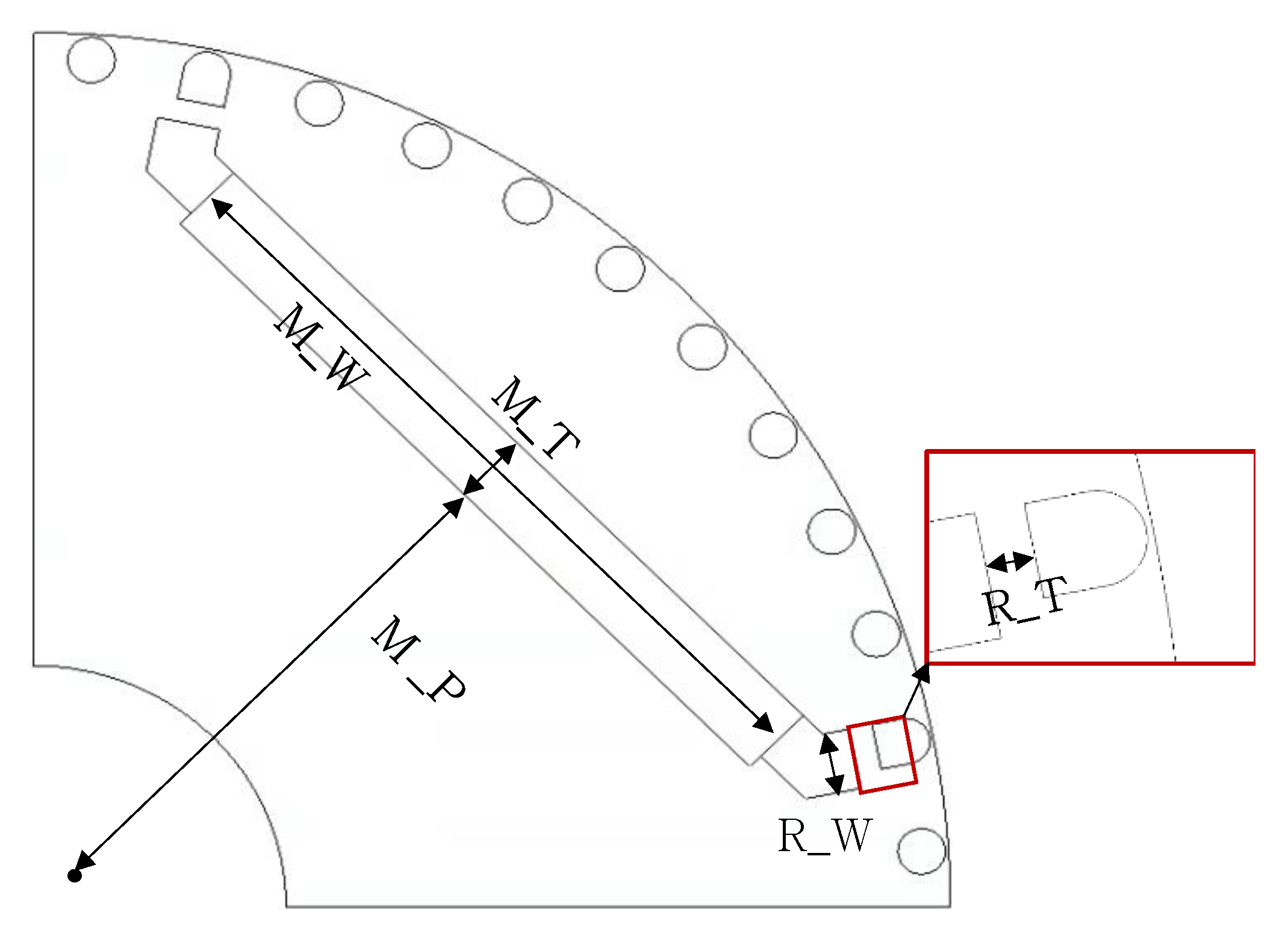
3.3. Optimal Design of Rotor Using Design of Experiments and Finite Element Analysis

Design of Experiment (D.O.E) is a method in which the user selects various factors that affect the characteristics of a model, uses experiments or simulates, and efficiently finds the optimum conditions of the model through these processes. In this paper, we designed experiments using the Taguchi method among various D.O.E.s. The design objective function and main design parameters are shown in Table 5 and Figure 9. The design objective function is maximizing the efficiency and power factor. Furthermore, the main design parameters are Permanent Magnet (PM) position, PM thickness, PM width, rib thickness, and rib width. The motor performance, varying the design parameters, is analyzed using FEA. From the FEA results, the objective function is analyzed. Figure 10 and Figure 11 show the main effect plots of the efficiency and power factor according to the design parameters. As shown in Figure 10 and Figure 11, varying the position of the PM and the thickness of the PM makes a large difference in efficiency and power factor. Efficiency and the power factor are increased by moving the PM closer to the surface of the rotor. However, if the position of the permanent magnet is too close to the aluminum bar, it will be difficultfor aluminum die-casting. Therefore, it is necessary to take this into consideration when selecting an appropriate value. Increasing the thickness of the PM increases the efficiency and power factor, but the magnetic torque acts as a braking torque in the transient state. As a result, the motor cannot be driven at the rated speed. Therefore, it is important to select an appropriate thickness value. Additionally, the leakage flux would be minimized by reducing the thickness and width of the lip. However, there would be manufacturing difficulty if it was overly thin. Based on the above results, Figure 12 shows the final shape of the designed rotor.

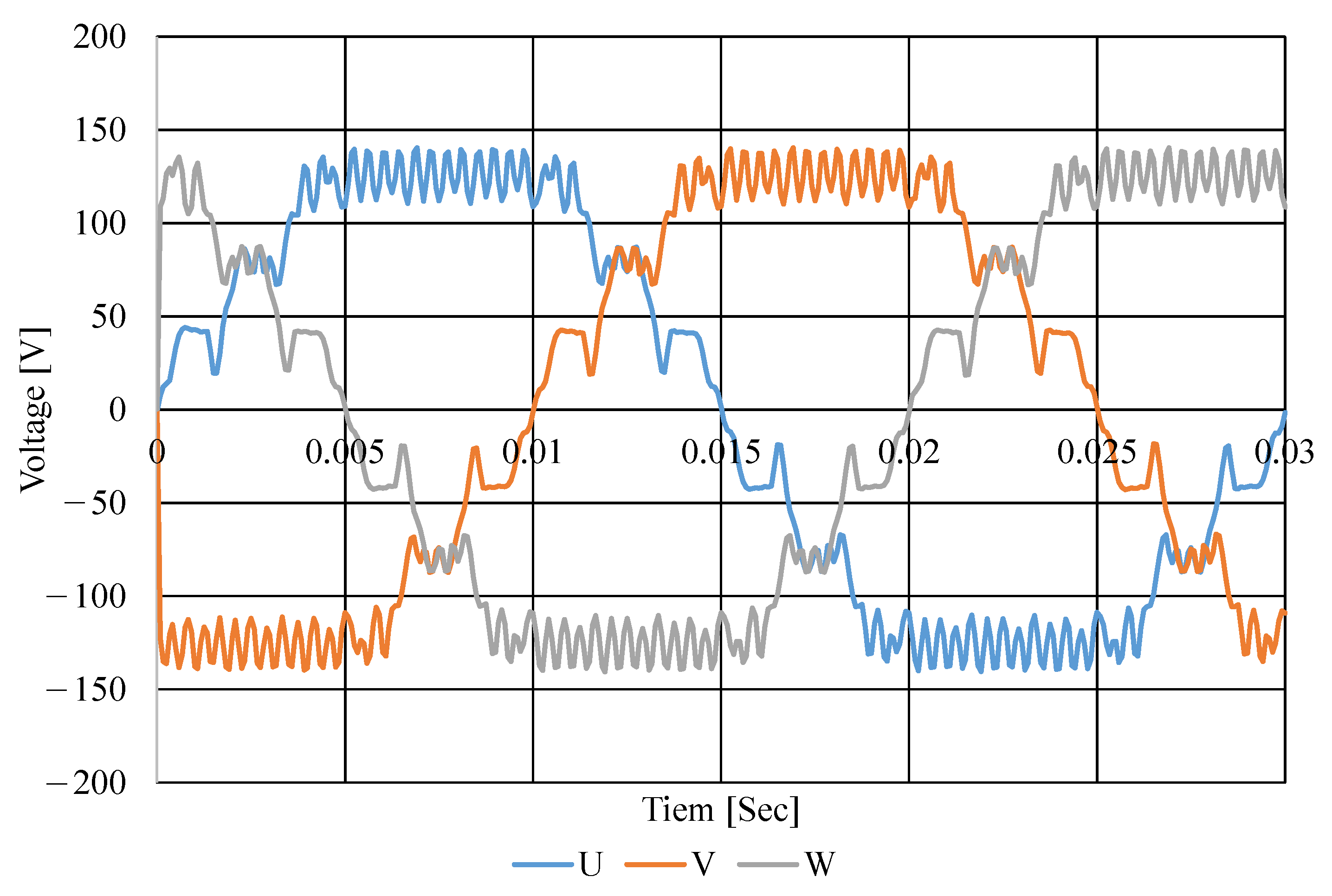
3.4. Design of the Stator Winding Using Finite Element Analysis
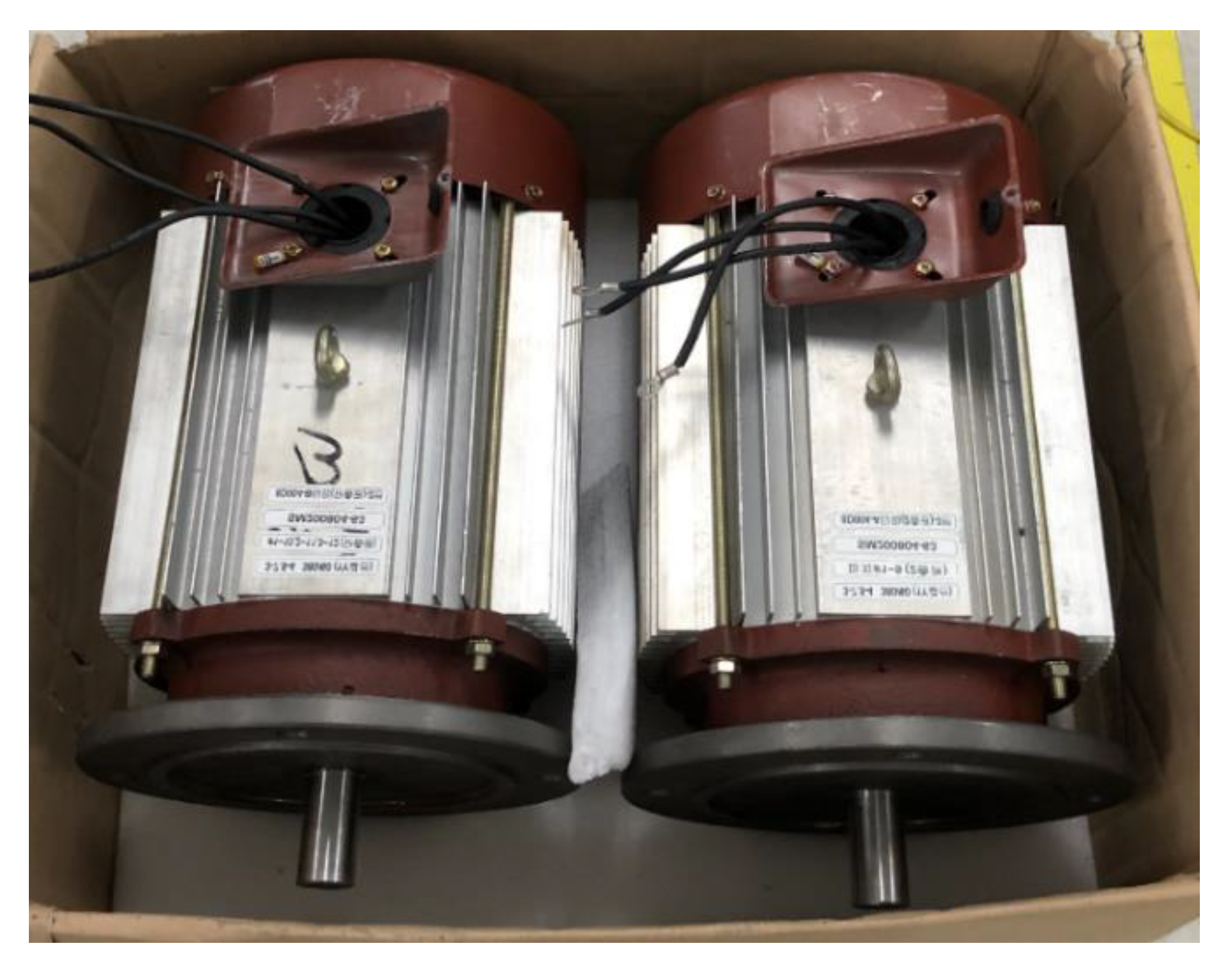
In this section, the stator windings are optimally designed through FEA. In this paper, the stator is wound with the distributed winding, and in the case of the distributed winding model, the fill factor is generally about 40%. In addition, the total area of the winding is calculated according to the predetermined slot area and fill factor. Furthermore, the number of turns of the winding can be calculated when the diameter of the winding is in the range of 0.7 to 0.9 mm. Meanwhile, since the LSPMSM is driven in the same way as the IPMSM in the steady state, the voltage equation of the IPMSM in Equation (2) can be applied.
V a = ( R s i d ω e m L q i q ) 2 + ( R s i q + ω e m L d i d + ω e m λ p m ) 2
Assuming the rated speed in Equation (2), the components by resistance ( R s i d ,   R s i q ) and by reactance ( ω e m L q i q , ω e m L d i d ) generally have a value smaller than the back-electromotive force component ( ω e m λ p m ). Therefore, ignoring those voltage drop components, the back-electromotive force component is 70~90% of voltage. Table 6 is the results of FEA according to the number of winding turns. As shown in the analysis results, the currents decrease as the number of winding turns grows. The generating torque is not changed until the number of winding turns is 18, since the back-electromotive force is increasing. However, the generating torque decreases when the number of turns is over 18, because the back-electromotive force exceeds the voltage limit. Therefore, referring to the results in Table 6, an appropriate number of winding turns should be carefully selected. Considering the results of torque and efficiency in Table 6, 14 turns and 16 turns are candidates for the final model. In the case of 14 turns, the power factor is lower, but it has higher efficiency. Furthermore, in the case of 16 turns, the copper loss is higher since the coil resistance increases with the decreasing wire diameter. In this paper, the main goal of LSPM design is achieving IE4 efficiency class (super premium class). Therefore, the 14-turn model is selected as the final model for higher efficiency.
Table 7 shows the motor parameters for the final design model. In the table, the stator resistance, back electromotive force (EMF) constant, d-axis inductance, and q-axis inductance are shown. Figure 13 shows the back electromotive force of the LSPMSM at a synchronous speed of 1800 RPM and a peak voltage of 140 V. Figure 14 shows the starting characteristics of the designed motor. Figure 15 shows the magnetic flux density of the motor.

4. Test Result

Figure 16 is a picture of the manufactured LSPMSM, and Figure 17 shows the motor setup on the test bench. The LSPMSM is driven by three-phase in-line power of 380 V and 60 Hz. Table 8 shows the test results. LSPMSM operates at a speed of 1800 RPM because it is designed as a 4-pole motor and rotates synchronized with the input voltage frequency of 60 Hz in a steady state. The measured efficiency is 94.10%, which is hardly different from the expected efficiency of 94.22% in the design. Furthermore, it is about 1.5% higher than the 92.6% requirement of the IE4 efficiency class. The current and torque are 13.6 A and 39.79 Nm, respectively, and both values are less than 0.1% different from FEA results. In addition, the input voltage and output are measured to be 219.05 Vrms and 7501.2 kW, respectively. Based on the test results, it can be confirmed that the manufactured motor fits well with the values analyzed by FEA. Therefore, it was confirmed that the manufactured LSPMSM can replace the existing induction motor while satisfying the requirements of the IE4 efficiency class. In addition, Table 9 shows the noise and vibration results measured in the test, and it is confirmed that there was no problem caused by noise and vibration in the steady-state.

5. Conclusions

In this paper, the optimal design of a Line-Start Permanent Magnet Synchronous Motor (LSPMSM) for replacing an industrial induction motor is studied with transient state analysis by FEM. Since it is a motor that replaces an industrial induction motor, the stator and frame maintain the original shape of the induction motor. Meanwhile, the rotor is optimally designed for the LSPMSM. The FEA and D.O.E are used to achieve the optimum rotor design, especially the position and size of the PMs and barriers. The designed LSPMSM achieves higher efficiency and output density than traditional induction motors. In addition, the performance of the manufactured motor was verified by a test. Induction motors account for 50 percent or more of total electricity consumption, but the efficiency of industrial induction motors is lower than that of PMSMs that use permanent magnets because copper loss occurs in the stator and rotor. A LSPMSM can be driven with the same performance as a PMSM in a steady state and be started without a controller and inverter. However, considering the results, due to the characteristic of the LSPMSM, it has more advantages in applications such as pumps and fans that have a low starting load. Moreover, it can be out of step and operate as an induction motor due to a sudden load change. Therefore, with more studies to improve the LSPMSM performance, industrial induction motors could be replaced with a high-efficiency LSPMSM. Finally, it could help to save energy and solve the carbon emission problem.

Author Contributions

Conceptualization, H.-B.H.; methodology, H.-B.H.; software, H.-J.P.; validation, H.-B.H., H.-J.P.; formal analysis, H.-J.P.; investigation, H.-J.P.; resources, H.-J.P.; data curation, H.-B.H., H.-J.P.; writing—original draft preparation, H.-B.H.; writing—review and editing, H.-J.P., K.-D.L.; visualization, H.-J.P.; supervision, K.-D.L.; project administration, K.-D.L.; funding acquisition, K.-D.L. All authors have read and agreed to the published version of the manuscript.

Funding

This work was supported by the Korea Institute of Energy Technology Evaluation and Planning(KETEP) and the Ministry of Trade, Industry & Energy(MOTIE) of the Republic of Korea (No. 20192010106780).

Institutional Review Board Statement

Not applicable.

Informed Consent Statement

Not applicable.

Data Availability Statement

The data presented in this study are available on request from the corresponding author. The data are not publicly available due to ongoing studies.

Conflicts of Interest

The authors declare no conflict of interest.

References

  1. Kim, H.; Park, Y.; Oh, S.-T.; Jeong, G.; Seo, U.-J.; Won, S.-H.; Lee, J. Study on Analysis and Design of Line-Start Synchronous Reluctance Motor Considering Rotor Slot Opening and Bridges. IEEE Trans. Magn. 2022, 58, 1–6. [Google Scholar] [CrossRef]
  2. Ferreira, F.; Baoming, G.; Almeida, A. Reliability and Operation of High-Efficiency Induction Motors. IEEE Trans. Ind. Appl. 2016, 52, 4628–4637. [Google Scholar] [CrossRef]
  3. Tabora, J.; Tostes, M.; Bezerra, U.; Matos, E.; Filho, C.; Soares, T.; Rodrigues, C. Assessing Energy Efficiency and Power Quality Impacts Due to High-Efficiency Motors Operating Under Nonideal Energy Supply. IEEE Access 2021, 9, 121871–121882. [Google Scholar] [CrossRef]
  4. Zöhra, B.; Akar, M.; Eker, M. Design of A Novel Line Start Synchronous Motor Rotor. Electronics 2019, 8, 25. [Google Scholar] [CrossRef] [Green Version]
  5. Chasiotis, I.D.; Karnavas, Y.L.; Scuiller, F. Effect of Rotor Bars Shape on the Single-Phase Induction Motors Performance: An Analysis toward Their Efficiency Improvement. Energies 2022, 15, 717. [Google Scholar] [CrossRef]
  6. Lu, X.; Iyer, K.L.V.; Mukherjee, K.; Kar, N.C. Development of a Novel Magnetic Circuit Model for Design of Premium Efficiency Three-Phase Line Start Permanent Magnet Machines With Improved Starting Performance. IEEE Trans. Magn. 2013, 49, 3965–3968. [Google Scholar] [CrossRef]
  7. Villani, M.; FABRI, G.; Credo, A.; Leonardo, L.; Collazzo, F. Line-Start Synchronous Reluctance Motor: A Reduced Manufacturing Cost Avenue to Achieve IE4 Efficiency Class. IEEE Access 2022, 10, 100094–100103. [Google Scholar] [CrossRef]
  8. Idziak, P.; Kowalski, K. Analysis of Selected Operating States of the Line Start Synchronous Reluctance Motor Using the Finite Element Method. Energies 2021, 14, 6825. [Google Scholar] [CrossRef]
  9. Seo, U.-J.; Kim, D.-J.; Han, P.-W.; Chun, Y.-D. FE-Aided Synchronization Analysis of Line-Start Synchronous Reluctance Motors. Appl. Sci. 2021, 11, 11673. [Google Scholar] [CrossRef]
  10. Yan, B.; Wang, X.; Yang, Y. Comparative Parameters Investigation of Composite Solid Rotor Applied to Line-Start Permanent-Magnet Synchronous Motors. IEEE Trans. Magn. 2018, 54, 11. [Google Scholar] [CrossRef]
  11. Baek, S.; Kim, B.; Kwon, B. Practical Optimum Design Based on Magnetic Balance and Copper Loss Minimization for a Single-Phase Line Start PM Motor. IEEE Trans. Magn. 2011, 47, 3008–3011. [Google Scholar] [CrossRef]
  12. Fei, W.; Luk, P.C.K.; Ma, J.; Shen, J.X.; Yang, G. A High-Performance Line-Start Permanent Magnet Synchronous Motor Amended From a Small Industrial Three-Phase Induction Motor. IEEE Trans. Magn. 2009, 45, 4724–4727. [Google Scholar] [CrossRef] [Green Version]
  13. Fu, W.N.; Chen, Y. A Post-Assembly Magnetization Method for a Line-Start Permanent-Magnet Motor. IEEE Trans. Appl. Super. 2016, 26, 4. [Google Scholar] [CrossRef]
  14. Kazakbaev, V.; Paramonov, A.; Dmitrievskii, V.; Prakht, V.; Goman, V. Indirect Efficiency Measurement Method for Line-Start Permanent Magnet Synchronous Motors. Mathematics 2022, 10, 1056. [Google Scholar] [CrossRef]
  15. Li, D.; Feng, G.; Li, W.; Zhang, B.; Zhang, J. Effect of Stator Slots on Electromagnetic Performance of a High-Voltage Line-Start Permanent Magnet Synchronous Motor. Energies 2022, 15, 3358. [Google Scholar] [CrossRef]
  16. Sarac, V.; Minovski, D.; Janiga, P. Parametric Analysis for Performance Optimization of Line-Start Synchronous Motor with Interior Asymmetric Permanent Magnet Array Rotor Topology. Electronics 2022, 11, 531. [Google Scholar] [CrossRef]
  17. Schommarz, P.D.; Wang, R.-J. Development of a Transient Synchronization Analysis Tool for Line-Start PM Motors. Energies 2022, 15, 9206. [Google Scholar] [CrossRef]
  18. Jeon, K.-W.; Chung, T.-K.; Hahn, S.-C. NEMA Class A Slot Shape Optimization of Induction Motor for Electric Vehicle Using Response Surface Method. In Proceedings of the 2011 International Conference on Electrical Machines and Systems, Beijing, China, 20–23 August 2011. [Google Scholar]
  19. Lee, G.; Min, S.; Hong, J.-P. Optimal Shape Design of Rotor Slot in Squirrel-Cage Induction Motor Considering Torque Characteristic. IEEE Trans. Magn. 2013, 49, 2197–2200. [Google Scholar] [CrossRef]
  20. Hirotsuka, I.; Tsuboi, K.; Ishibashi, F. Effect of Slot-Combination on Electromagnetic Vibration of Squirrel-Cage Induction Motor under Loaded Condition. In Proceedings of the Power Conversion Conference, Nagaoka, Japan, 6 August 1997. [Google Scholar]
  21. Kobayashi, T.; Tajima, F.; Ito, M.; Shibukawa, S. Effects of Slot Combination on Acoustic Noise from Induction Motors. IEEE Trans. Magn. 1997, 33, 2101–2104. [Google Scholar] [CrossRef]
  22. Zhang, D.; Park, C.S.; Koh, C.S. A New Optimal Design Method of Rotor Slot of Three-Phase Squirrel Cage Induction Motor for NEMA Class D Speed-Torque Characteristic Using Multi-Objective Optimization Algorithm. IEEE Trans. Magn. 2012, 48, 879–882. [Google Scholar] [CrossRef]
Figure 1. Efficiency of IE1 (Standard) and IE4 (Super Premium) according to IEC 60034-30.
Energies 15 09644 g001
Figure 2. The rotor of a 4-pole LSPMSM.
Energies 15 09644 g002
Figure 3. Rotor slot shape classification according to NEMA standard.
Energies 15 09644 g003
Figure 4. Torque–speed characteristics of induction motors by NEMA class.
Energies 15 09644 g004
Figure 5. FEA model for transient analysis.
Energies 15 09644 g005
Figure 6. FEA results in the time domain depending on the rotor slot size (normal inertia).
Energies 15 09644 g006
Figure 7. FEA results in the time domain depending on the rotor slot size (maximum inertia).
Energies 15 09644 g007
Figure 8. Magnetic flux density with the maximum inertia.
Energies 15 09644 g008
Figure 9. Design parameter of LSPMSM.
Energies 15 09644 g009
Figure 10. Main effect plot of efficiency.
Energies 15 09644 g010
Figure 11. Main effect plot of the power factor.
Energies 15 09644 g011
Figure 12. Optimal design model.
Energies 15 09644 g012
Figure 13. Back EMF of the designed LSPMSM at 1800 RPM.
Energies 15 09644 g013
Figure 14. Speed and torque of the designed LSPMSM.
Energies 15 09644 g014
Figure 15. Magnetic flux density of the designed LSPMSM.
Energies 15 09644 g015
Figure 16. The manufactured LSPMSM.
Energies 15 09644 g016
Figure 17. Test setup of the LSPMSM.
Energies 15 09644 g017
Table 1. Specifications for design model.
VariablesValueUnit
Rated Power7500W
Rated Torque39.8Nm
Number of Poles4-
Number of Slots36-
Stator Outer195mm
Rotor Inner116mm
Table 2. The recommended slot combination of induction motor.
PolesNumber of Stator SlotsNumber of Rotor Bars
22418, 20, 22, 28, 30, 33, 34
3625, 27, 28, 29, 30, 43
4830, 37, 39, 40, 41
42416, 18, 20, 30, 33, 34, 35, 36
3628, 30, 32, 33, 34, 45, 48
4836, 40, 44, 57, 59
7242, 48, 54, 56, 60, 61, 62, 68, 76
62420, 22, 28, 44, 47, 49
3634, 36, 38, 40, 44, 46
4844, 46, 50, 60, 61, 62, 82, 83
Table 3. FEA results depending on the rotor slot size (normal inertia).
Bar Size
(mm)
Torque
(Nm)
Speed
(r/min)
Current
(Arms)
BarLoss
(W)
Copper Loss
(W)
Efficiency
(%)
Power Factor
(%)
0.539.23180021.32127.41294.691.4560.84
139.65180021.56137.59301.2291.3560.36
1.539.66180022.19115.2319.0191.4357.5
239.66180026.181.14441.390.4654.05
2.539.64180036.6101.43867.7185.7739.4
339.56180055.07212.11965.2775.1931.18
3.539.59180078.47508.243990.2160.9227.65
Table 4. FEA results depending on the rotor slot size (maximum inertia).
Slot Size
(mm)
Torque
(Nm)
Speed
(r/min)
Current
(Arms)
BarLoss
(W)
Copper Loss
(W)
Efficiency
(%)
Power Factor
(%)
0.533.61868.4116.226094.638754.7416.3534.37
139.23948.4125.579122.6810,217.4216.3740.24
1.539.541491.7115.33646.498613.5632.8436.73
239.66180026.181.11441.3190.4652.57
2.539.64180036.6101.42867.8485.7739.40
339.57180055.08211.91965.8575.1931.17
3.539.55180078.5508.19399360.8827.62
Table 5. Object functions and design variables.
Design Objective FunctionsDesign Variables (Level)
Max (Efficiency)
and
Max (Power Factor)
1. Permanent Magnet Position (5 Level)
2. Permanent Magnet Thickness (5 Level)
3. Permanent Magnet Width (5 Level)
4. Rib Thickness (5 Level)
5. Rib Width (5 Level)
Table 6. FEA results depending on the number of stator winding turns.
TurnsTorque
(Nm)
Torque Ripple
(%)
Speed
(rpm)
Current
(Arms)
Efficiency
(%)
Power Factor
(%)
1239.643.33180026.289.4949.08
1439.8248.62180012.8994.2295.02
1639.8953.22180012.3294.1699.66
1839.8766.21180012.7793.2696.85
2024.281808.25962.2362.6012.2660.86
Table 7. Motor parameters for the final model.
VariablesValueUnit
Stator resistance0.282W
Back EMF constant4.54V·s
d-axis inductance ( L d )16.31mH
q-axis inductance ( L q )34.59mH
The moment of inertia ( J )0.022kg·m2/s
Table 8. Test results of the LSPMSM.
Torque
(Nm)
Speed
(rpm)
Voltage
(Vrms)
Current
(Arms)
Copper Loss
(W)
Output
(W)
Efficiency
(%)
Analysis39.82180022012.8946.857507.794.22
Test39.791800219.0513.652.167501.294.1
Table 9. Test results of noise and vibration.
VariablesValueUnit
Noise71.5dB
Vibration1.0mm/s
Publisher’s Note: MDPI stays neutral with regard to jurisdictional claims in published maps and institutional affiliations.

