Review

Different Topologies of Electrical Machines, Storage Systems, and Power Electronic Converters and Their Control for Battery Electric Vehicles—A Technical Review

by
Elango Sangeetha
and
Vijayapriya Ramachandran
*
Vellore Institute of Technology, School of Electrical Engineering, Vellore 632014, Tamil Nadu, India
*
Author to whom correspondence should be addressed.
Energies 2022, 15(23), 8959; https://doi.org/10.3390/en15238959
Submission received: 16 August 2022 / Revised: 30 September 2022 / Accepted: 25 October 2022 / Published: 27 November 2022
(This article belongs to the Collection "Electric Vehicles" Section: Review Papers)

Abstract

:
Electric vehicles (EVs) are emerging as an alternative transportation system owing to a reduction in depleting lubricates usage and greenhouse gas emissions. This paper presents a technical review of each and every sub-system and its feasible control of battery EV (BEV) propulsion units. The study includes the possible combination of electrical machines (EMs), storage system, and power electronic converters and their associated control strategies. The primary unit, i.e., EM, is the heart of the EV, which is used to drive the vehicle at the desired speed as well as to restore the regenerative braking (RB) energy that is generated to enhance the overall system reliability. To electrify the transportation sector, it is necessary to include new options of power electronic converter topologies and their associated control strategies for numerous reasons, which include extracting maximum power from sources in case the EV is powered from renewable energy resources, boosting the energy storage capability for longer electric range, managing power flow from the source to battery or battery to vehicle or vehicle to battery, and regulating the speed of the vehicle and braking control. Based on the survey, the suitable combination of sub-systems and their control for three and four-wheeler EVs are summarized in this paper.

1. Introduction

Electric vehicles (EVs) are foreseen to be a promising technology option in the transportation sector with the advancement in various technologies such as power electronics, digital controllers, and electrical machines (EMs). EVs are widely regarded as a feasible solution for reducing environmental pollution and ground transportation’s reliance on fossil fuels [1]. Greenhouse gas emission from automotive exhausts is the most significant contributor to global warming, and every country has already been provided with a deadline to not exceed the emission limit stated by the United Nations. To reduce locomotive carbon footprint as the demand for clean and green product development increases, the most well-known alternative is automotive electrification which can be achieved by EMs. Electric motoring and generating systems find their application in vehicle traction not only due to more vehicle electrification but also because of increasing operational efficiency and zero-emission [2,3,4]. The various combination of EVs includes plug-in hybrid EVs (PHEVs), battery EVs (BEVs), and hybrid EVs (HEVs) [5]. BEVs have no exhaust emissions and are considered the most appealing alternative for long-term carbon dioxide (CO2) emissions reduction. Despite the fact that BEVs reduce CO2 emissions, consumer acceptance in the passenger vehicle industry faces challenges such as limited driving range and long battery charge time [6].
The general block diagram of the BEV propulsion system considered in this study is shown in Figure 1. The system consists of sub-systems such as the energy storage system (ESS), power electronic converters (PECs), and EM and its related controller. The sub-systems employed in EV are not unique and different configurations of such systems are implemented in real-time applications. Additionally, studies have been carried out with many new technologies for each and every sub-system to bring forth the importance of novelty in their proposed system. Research work has also been reported to review the current, emerging, and future trends of propulsion sub-systems. The current technologies, future trends, and requirements of EV propulsion systems are reviewed in ref. [7]. Various types of electric motors, such as induction machines (IMs), switched reluctance machines (SRMs), synchronous reluctance machines (SyncRMs), and PM-Assist SyncRMs for EV application, are investigated. Additionally, the emerging trend of semiconductors and their significance in power converters is emphasized with the required power conversion stages. The conversion stages include a propulsion inverter, an onboard battery charger, and a DC–DC converter for converting the high voltage to 12 V DC. The advantages of ESS, such as lithium-ion batteries and lithium-air technology, are highlighted. Finally, the concept of different charging types, such as AC and DC charging, inductive power transfer, and the general requirements of BEV and PHEV systems are addressed. However, the selection of motors, storage systems, power converters, and controls for specific EVs and their application is not specified clearly.
The advanced and emerging EMs for EV applications, including design ideas, topologies, structures, methodologies, control strategies, foresight, merits and demerits, are reviewed in ref. [8]. Advanced EMs such as IM, SRM, permanent magnet synchronous machine (PMSM), and PMA-SynRM and emerging EMs such as stator-PM, flux-controllable, double-stator, and double-rotor are also discussed. Machine design methodologies in terms of finite element and analytical methods, with respect to system-level machine design, power loss, and high-efficiency design aspects, are discussed further. Structure, pros and cons of EM drive control techniques such as field-oriented control (FOC), direct torque control (DTC), and model predictive control (MPC) with ancillary controls such as fault-tolerance, sensorless, and high-frequency control are presented. Emerging technologies such as integrated motor drive, wireless motor drive, flying EVs with ultra-lightweight propulsion, autonomous driving of EVs, 5G communication, and artificial intelligence are also discussed.
A brief review of the current trends and emerging technologies of EVs are discussed in ref. [9]. The necessities of power electronic components and electric motor drives for enhanced operation of EVs are also reviewed. Primarily, the basic concepts and general classification of HEVs are discussed and the fundamental concept of the conversion of HEVs into PHEVs is presented. Consequently, a fuel-cell-based vehicle propulsion system with its associated components for vehicles is demonstrated. Eventually, PEC requirements such as research on switches, switch packaging technologies, manufacturing processes, switching topology, the necessity of a cooling system, and converter control techniques such as the switching method, electromagnet interference (EMI) filter, and fault-tolerant topology are highlighted. Overall, the paper presented the general requirement of PHEV with respect to the power source, power unit control, and PEC. In ref. [10], a novel control technique for EV traction motor systems is reviewed, mainly focusing on DTC and FOC. A detailed design of conventional DTC followed by the implementation of possible control techniques such as space vector modulation (SVM), fuzzy logic control (FLC), sliding-mode control (SMC) and artificial neural network (ANN) is discussed. Similarly, the application of FOC in the EV drive system is presented. The requirements of additional control strategies, such as flux-weakening and sensorless control for both DTC and FOC, are highlighted.
Different ESSs, such as batteries, supercapacitors, fuel cells, and hybrid storage, along with power, temperature, and heat management, are illustrated in ref. [11]. Considering the lithium-ion battery is the most powerful and popular choice of storage, the paper discusses various aspects such as energy management systems (EMSs), challenges, issues, and recommendations for future work. EMS control includes battery monitoring, charging–discharging control, state-of-charge estimation, protection, and fuel-cell equalization. The paper also discusses some of the critical aspects of lithium-ion batteries, including temperature and safety, life-cycle and memory effects, environmental effects, and recycling processes.
In ref. [12], a summary of present fast charging technique limitations, classification and comparison of different approaches to determine the state of health of fast charging strategies, evaluation of research gaps, and recommendations for further development is highlighted. A review of the current status and implementation of battery chargers, charging power levels, and infrastructure for plug-in EVs and PHEVs is provided in ref. [13]. Battery charger topologies such as interleaved unidirectional chargers, single-phase unidirectional multilevel chargers, and three-level diode-clamped bidirectional chargers are discussed. Bidirectional chargers are also illustrated with single-phase half-bridges, single-phase full-bridges, and three-phase full-bridges. Furthermore, power on-board and off-board charger levels 1, 2, and 3 and their corresponding infrastructure are detailed. Other concepts, such as integrated and contactless inductive charging, are also discussed. International charging codes, standards, isolation, and safety requirements for EV chargers are also summarized.
The major contribution of this paper includes the selection of a suitable power converter and its controller, EM and ESS, for EV application. This paper is organized as follows: Section 2 reviews different types of the EMs topologies and their possible basic, advanced, and additional control techniques. Passive and active ESSs are summarized in Section 3. Section 4 presents different types of power converters employed in EV applications. The summary of sub-system topology for three and four-wheelers is highlighted in Section 5. Finally, Section 6 concludes the paper.

2. Electrical Machines (EMs)

Generally, the EV design starts with the selection of EMs as the machine determines the propulsion system characteristics, ESS capacity, and power converter ratings. The motor/generator (MG) system is the basic concept of any EM used in an EV. The EM operates as a motor to provide the required torque to start the engine, and once the engine starts, the same EM can be transformed into a generator to produce electrical power during deceleration. The various types of EMs and their associated control for EV application are provided in this section highlighting the purposes, real-time implementation, pros, and cons.

2.1. EMs Control Technologies
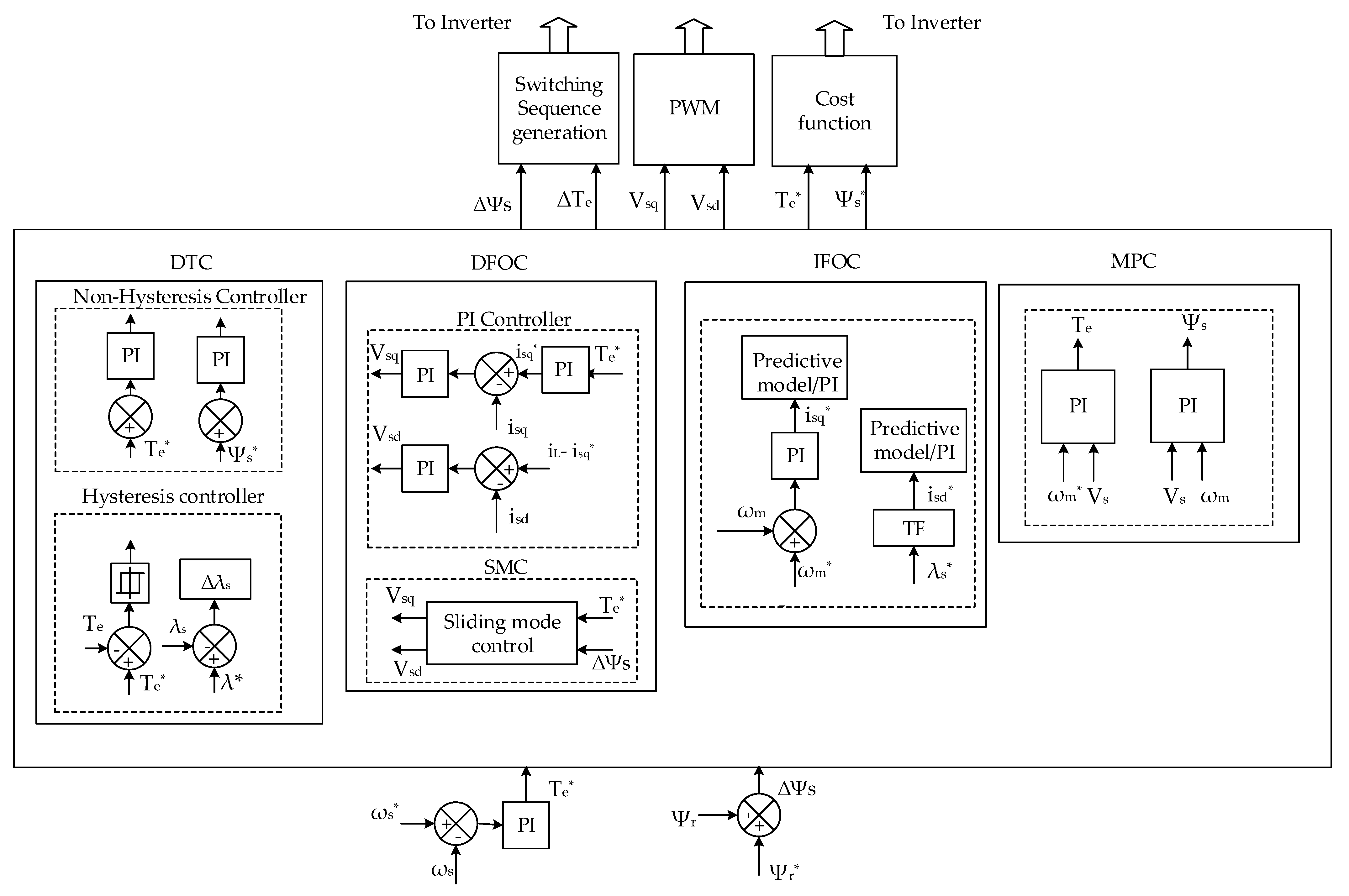
The performance evaluation of EM is mainly decided by the type of the PEC and its associated control strategies implemented. The two-level PEC in the controller is employed with FOC, DTC, or MPC to achieve the desired control of EM [14].

2.1.1. FOC

During motoring and generating mode, the reference value of the stator-current corresponding to real power (can be either d or q-axis current, and q-axis component is considered throughout this paper), i.e., the q-axis component (isq), is derived based on the output of the torque regulator and voltage regulator, respectively. The FOC can be either the direct FOC (DFOC) or indirect FOC (IFOC) based on the method of deriving the angle information which is needed to transform the electrical quantities from three-phase ac to synchronous reference frame (SRF) or vice versa. IFOC schemes evade flux regulators to determine the flux position information. However, the rotor (or stator)-flux orientation and regulation are obtained by deriving the relationship between the rotor (or stator) flux and stator-current based on the machine–model equations. Contrarily, DFOC schemes employ flux observer regulators to determine the flux amplitude and location. The output of the flux regulator generates the stator current reference value in the d-axis, and hence the direct control of flux can be achieved through constant frequency and current regulation.

2.1.2. DTC

The basic structure of DTC with an outer torque regulator is shown in Figure 2. In DTC strategies, the inner-current loops and pulse width modulation (PWM) blocks are replaced by hysteresis controllers and a sector identifier. Based on stator-flux errors, instantaneous torque, and angular position of the estimated voltage vector, the sector identifier outputs the proper switching signals through the optimal switching table.

2.1.3. Model Predictive Control (MPC)

The outer speed loop of MPC remains the same as FOC, and the inner current loop is replaced with a predictive model. MPC involves three stages. In the first stage, stator, current, and voltage are used to predict the present system states. The second stage includes the prediction of the system’s next states under different current and voltage vectors using the corresponding predictive model. In the third and final stage, the cost function is used to select the optimal voltage vector.

2.1.4. Fault Tolerant Control (FTC)

The EM drive system in EVs experiences many failures, such as open circuit faults, short circuit faults, and current sensor errors due to the presence of electric and mechanical ports. The impact of these faults and errors is mitigated using FTC, which includes fault diagnosis and fault tolerance. Fault diagnosis can be carried out employing calculation-based methods such as phase current FFT analysis and phase current coordinates transformation. Additionally, fault diagnosis uses additional device-based methods such as resistance observer and DC bus current regulation. Fault tolerance includes phase current reconstruction, torque ripple minimization, and offset compensation to mitigate open circuit, short circuit, and current sensor faults, respectively.

2.2. Induction Machine (IM)

IM with magnetic field windings and armatures on the stator and rotor, respectively, along with the elimination of brushes and commutators, operate as a brushless drive system. IMs find their application in EVs due to low construction and maintenance cost, improved robustness and reliability, availability of starting torque and good starting performance, high power level and efficiency, reduction in vehicle drive system cost and losses, and ultimately, improved efficiency of the overall vehicular system. Different classifications of IMs, such as squirrel-cage (SCIM), wound-rotor (WRIM), and doubly fed (DFIM), are employed in EVs [14,15,16,17,18,19,20,21,22,23,24,25,26,27,28]. To become competitive with PM machines in relation to this power and torque density, stator windings with bar wound wires and rotor cages with casted copper conductors are reported as an alternative solution [15]. The general structure of DFOC and IFOC for IM-based EVs is depicted in Figure 2. The various control strategies applied for IMs for EV applications, including basic, advanced, emerging, and future scopes addressed in various research works, are summarized below.
SCIM is a competitive machine for MG systems possessing the advantages of simple and robust construction, cheaper cost and low maintenance, and better overload proficiency. The motoring/generating process involves three stages such as the starting process, the transition process, and the generating process. During the process, the ignition power supplies the real and reactive power to the MG system via the PEC. The MG system operates as a motor and provides the torque needed to drive the engine and transforms the electric power into mechanical power during this process. Once the engine starts, it accelerates and reaches a certain speed, and during the transition process, the MG system gradually starts to transition to generating mode with only a smaller percentage of required torque. During the generating process, the MG system builds up the voltage, and after reaching the commanded level, the system provides electrical power which is stored in the battery with the help of the same PEC. Through this process, the IM transforms the mechanical power into electric power. The performance evaluation of start-up, motoring, transition, and generating processes is mainly decided by the type of the PEC, and its associated control strategies implemented [14]. The outer torque loop makes the control process consistent during the starting and generating modes. Nevertheless, the hysteresis controllers and optimal switching table introduce variable switching frequencies and torque ripples. To overcome those problems, the PI controllers and SVM can be selected, and the direct flux vector control can be used to manage the stator flux’s rotating speed and amplitude [16].
In ref. [17], the motoring and generating mode controller of IM is synthesized by the NN and voltage regulator based on two energy systems, namely the main and an auxiliary system, respectively. The controllers employ recurrent high-order NN, an inverse optimal controller, and a super-twisting observer for system identification, trajectory tracking, and state estimation, respectively. Torque trajectory tracking and state estimation are implemented correspondingly to reject the undesired disturbances and to estimate the rotor magnetic fluxes. Additionally, the paper addresses the RB control issue, i.e., when the battery cannot be able to store the generated energy during the generating mode of operation. During this condition, an auxiliary energy system consisting of a supercapacitor (SC) and a buck–boost converter is activated to recover the braking energy, and this, in turn, is used to power the motor during acceleration.
A new configuration of cascaded DFIM for EV application is presented in ref. [18] as a future trend. The configuration enables the synchronous control of both power and control winding currents. The drive system indirectly couples the power and control winding through the induction mechanism, and the system is controlled similar to a traditional IM to attain high torque density. A different dual-electrical-port control scheme with only one proportional-integral (PI) controller is proposed possessing numerous advantages such as the elimination of complex coordinate transformation, enhanced operation of the system to obtain an ideal linear relationship between torque and the corresponding current component, and minimum slip frequency to reduce core losses. A low-voltage IM is employed for EV application in ref. [19] with the introduction of a MPC-based field-weakening scheme instead of the PI regulator to obtain a wider range of operating speed. Compared to the PI regulator, the proposed MPC possess several advantages, such as a small signal model to precisely predict the stator voltage and speed instead of the mathematic model as in the case of the PI regulator. Additionally, the scheme uses incremental form to obtain smooth output, whereas, in the PI regulator, the proportional gain kp needs to be tuned in a wider range within a short time to obtain the smooth output.
A sensor fault-tolerant control (FTC) for the IM drive system is implemented in ref. [20]. The control structure is framed to switch between two techniques: IFOC and speed control with slip regulation in the case of healthy and failed current sensors, respectively. In contrast to FOC and DTC, a loss model-based controller for IM is implemented in ref. [21]. Primarily, loss is calculated using the energy balance equation of IM’s port-controlled Hamilton model. Based on the conceived loss model, the obtained loss is converted into steady-state currents, which in turn are used to frame the loss minimization algorithm. The algorithm is implemented using interconnection and damping assignment to offer high-efficiency driving solutions for EVs. Compared to conventional FOC or DTC, the proposed method has significant merits such as simple control design, higher optimization speed, and lesser percentage of torque oscillation.
A dynamic maximum torque per ampere (MTPA) control is demonstrated in ref. [22] to minimize the stator current amplitude for a given step variation of the torque reference. IM is widely employed as the core propulsion component in many commercial EVs, as shown in Table 1. Although IM possesses several advantages, the efficiency of the machine is less than PMSM and highly precise speed control is challenging.

2.3. Permanent Magnet (PM) Machines

PMSM is increasingly employed in passenger EVs due to enhanced machine performances, high torque density, power density, and efficiency. The main classification of PMSM, i.e., surface-mounted PM (SPM) and interior PM (IPM), both have been progressively applied in commercial EV applications based on their control technique [29,30,31,32,33,34,35,36,37,38,39,40,41,42]. Similar to IM, the basic control of PMSM can be obtained by employing FOC, DTC, or MPC. Considering the significance of PMSM in EVs, ref. [29] detailed the design procedures of two machines: IPM-based PMA-SynR and concentrated-winding SPM using design equations, finite element analysis, and multi-objective optimization algorithms. An interior V-type PM machine with a strengthening rib and magnetic bridge is designed for EV application in ref. [30]. The proposed machine has the advantage of high torque density and high efficiency (94%) in the constant torque region of 40 Nm. However, under the rated and peak running period, it is reported that the machine is subjected to a significant rise in temperature. In ref. [31], a novel double-rotor flux switching PM machine is introduced for EVs with the ability of magnetic differential. The proposed work is intended to provide a new set of winding to magnetically couple with the rotors such that the magnetic coupling winding field interacts with the PM field of the rotors. This paves the way to generate differential torque between the wheels to attain accurate cornering during vehicle steering. Subsequently, the proposed system offers higher efficiency and density than the traditional mechanical differential system while providing higher reliability and safer operation than the electronic differential system. As high-fidelity IPM machines are needed to capture physical effects such as magnetic saturation, simulation-based design optimization is proposed in ref. [32].
A torque control strategy based on MPC Is presented to efficiently attain torque demand in EVs. The MPC-based control scheme meets the EV propulsion requirements such as fast and smooth torque regulation, energy consumption reduction, and current saturation limit regulation, which leads to significant energy saving and improved efficiency. To achieve fast control in predictive processes, a search tree is built to select the optimal inputs using a dynamic programming algorithm. Finally, a pruning method is designed to check the aspirant inputs that can step into the next stage to reduce the input sequences evaluation computational burden. In ref. [33], a new method is investigated to decrease the PWM carrier harmonic iron loss in the low torque region and to improve the vehicle mileage by revealing the relationship between phase current and carrier harmonic iron loss. Additionally, the novel loss reduction technique is validated with the proposed concentrated winding PMSM with two sets of three-phase windings. The efficiency of the motor is 2% higher than that of the conventional machine. Using the maximum torque current ratio strategy, an energy efficiency optimization control is proposed in ref. [34] with strong universality and a robust design, as the technique does not depend on motor parameters. A modified FOC algorithm is presented in ref. [35] to ensure smoother starting of the machine and to avoid the initial jerk of the machine, and in ref. [36], a motor control method during anti-lock conditions is proposed. To suppress the torque ripple, a modified DTC method is proposed based on bus voltage vector selection in ref. [37]. A speed adaptive control structure is developed in ref. [38] to overcome the risk of high current during high-speed operation and to extend the operating range of speed.
A hierarchical control strategy is proposed for an EV with a two-speed automated mechanical transmission to address the issues involved during the downshifting process of RB. For the upper controller, an off-line calculation and online look-up table method are adopted to obtain the optimal downshift point, and a series RB distribution strategy is designed. For the medium controller, a nonlinear sliding mode observer is designed to obtain the actual hydraulic brake torque. For the lower controller, cooperative control of RB and hydraulic braking is provided to ensure brake safety during the downshift process, and a resembling PWM scheme is brought forward to regulate the hydraulic brake torque during the downshifting process. The system efficiency is 86.51% [39].
In ref. [40], an electrical braking torque limit trajectory is designed for both IPM and SPM based on regenerative power analysis to improve the RB of EVs. The torque limit trajectories are included in the controller design, as depicted in Figure 3, with the provision of harvesting maximum regenerative energy under any situation by the battery. The effective utilization of RB energy during extreme conditions and its controller design for an EV is brought forward in ref. [41]. The system employs a hybrid energy storage system (HESS) which consists of a Li-ion battery and ultra-capacitor (UC) as well as a dissipative resistor. The UC will be mainly involved in braking and traction modes. The role of the resistor is to protect the dc bus and the battery according to the voltage and current constraints. The size of the elements takes into consideration the extreme braking conditions of the vehicle. Controllers are used in order to regulate the various electrical variables of the overall system. A sequential logic controller is also introduced. The role of the sequential logic controller is to activate the different existing regulation controllers and to ensure the switching between the storage elements depending on the system states.
A new approach is presented in ref. [42] to emulate EV braking performance on a motor with brake force distribution between RB and friction braking of both the front and rear axles. A brake controller is designed considering both the RB and friction braking limitations. The performance of the proposed brake controller is validated in real-time by integrating the design into the EV hardware-in-the-loop control structure. The RB contributions to EV’s energy efficiency improvement are brought out by evaluation methods, and the corresponding energy flow is analyzed [43,44,45,46,47,48]. Additionally, three different control strategies are proposed, namely serial 1, serial 2, and parallel control strategy. The performance evaluation of all three control strategies is compared, and it is reported that the serial 2 control strategy offers considerably higher regeneration efficiency than the parallel strategy and serial 1 strategy for the prevailing road condition. To enhance the driving range, commercial passenger EVs are adopting PMSMs as the essential propulsion system, as shown in Table 2. Despite high efficiency and power density, PMSM also possesses disadvantages. The flux-weakening technique required under high-speed regions increases the risk of demagnetization and involves complex controller design. Furthermore, rare-earth PMs are prone to eddy current loss, demagnetization risk, and mechanical failure. Henceforth, the reliability and fault tolerance of EV systems must be addressed properly. Eventually, the vibration of the EV propulsion system is significant as PMs introduce strong magnetic forces.

2.4. Switched Reluctance Machine (SRM)

Being a family of doubly salient topology, SRM is suitable for small-sized and service-type EVs owing to distinct features such as the absence of rotor windings or PMs, which leads to simple, robust, and reliable rotor structure, high-speed drive range, high power density, absence of rotor magnetic bridges, and improved safety and fault tolerance capability. Considering the abovementioned unique features, research work has been reported to design a new SRM for practical passenger EVs.
As mentioned, a new 6/16 three-phase in-wheel SRM with the ideas of multi-teeth per stator pole and more rotor poles than stator teeth is proposed in ref. [49]. The purpose of the new design is to attain wider operating speed and enhanced torque output. The design employs a genetic algorithm method to optimize the motor parameters in order to achieve the maximum torque output. In ref. [50], a multi-objective Taguchi-chicken swarm optimization algorithm is employed considering six objective functions such as maximum speed, accelerated time, maximum climbing gradient, energy usage ratio, and torque ripple factor to design an SRM. To fulfill all the requirements required for electric propulsion, such as active cruise control, anti-slip control, and active damping of mechanical drivetrain oscillations, a modified control with a sampling frequency is 100 HZ is presented in ref. [51]. In ref. [52], DTC, with a fast-nonlinear modeling method, is proposed to enhance the accuracy of the system by analyzing the flux-linkage using the Fourier series and Kriging model. A high-performance digital PI regulator for current control is presented in ref. [53], considering the nonlinear behavior of saturation, back electromotive force (EMF), and mutual coupling. To obtain enhanced machine performance, a multi-objective optimization algorithm is presented considering maximum torque, minimum copper loss, and torque ripple.
To improve the braking performance and to recover the braking energy under sliding braking conditions, RB control is proposed based on multi-objective optimization technique, braking force, and angle optimization controller as depicted in ref. [54,55]. The drive system is designed accounting the current regulation and braking torque control strategy. Upon testing, it is validated that the proposed control strategy can effectively balance braking energy recovery efficiency, braking comfort, and charging current performance. SRM are prone to torque ripple and electromagnetic vibration, which may cause acoustic noise pollution for drivers and passengers. Additionally, due to its torque density limitation, SRM-based passenger EV propulsion systems are hardly found in real-time applications, as shown in Table 3.

2.5. Synchronous Reluctance Machine (SyncRM)

In recent years, there has been a scarcity of rare-earth materials, and the operation of rare-earth PMs hardly performs in extreme conditions. This paves the way to employ rare-earth-free and PM-free EMs such as SyncRMs in EV applications. The machine provides advantages such as high reluctance owing to rotor pole saliency, higher efficiency, and lower cost. Likewise, using rare-earth free PMs instead of SyncRMs, which are defined as PMA-SyncRMs, can improve the overall machine performance. These types of machines are suitable for low-cost EV drive applications owing to distinct features: improved reliability, low overheating risk and high rotor strength, easy realization of flux weakening and high-speed driving strategy, and higher power density than PMSM.
SyncRM is identified as a suitable variable-gear drive for EV applications, and many research works have been reported in terms of improving the machine design, especially the rotor design, as the average torque is due to the rotor anisotropy. While position-sensorless control strategy is concerned, the main drawback of such a machine is due to limited saliency magnitude; the drive’s ability is limited at zero or very small current magnitudes. To increase the SyncRM saliency at zero reference currents, an epoxy–resin-casted rotor with the elimination of iron ribs is proposed in refs. [56,57,58,59,60]. The performance of the proposed design is validated by employing finite-element analysis, and the results are compared with the traditional flux barrier SyncRM rotor. In ref. [57], a deep investigation of SyncRM capabilities is carried out with respect to traction application requirements and compared with the PMA-SyncRM. Rotor configurations with multiple flux barriers per pole results in high rotor saliency in turn high average torque. It is validated in the proposed work that SyncRM exhibits a slight decrease of torque density with respect to PMA-SyncRM but high overload capability, wider operating range of resultant torque, and torque ripple falls within the specified limit even under high overload conditions. However, the main drawback of SyncRM is the worsening of torque under flux-weakening operations. The three main factors the manufacture considered for traction machine design are cost, weight, and size. In particular, the machine’s proper size estimation is the major design step to be decided before attempting the rotor geometry design. This is crucial in passenger vehicles in which compactness is a requirement and the size and weight are indeed the design limitations. In ref. [58], the methodology for sizing a SyncRM is presented. The performance of the advanced control technique employed in EVs is provided in Table 3. The main advantages of PMA-SyncRM are increased torque density and power factor. Nevertheless, the drawback is the risk of demagnetization due to PMs adoption which in turn highly limit the machine’s maximum overload capability, which is a salient requirement of a traction motor. Additionally, the design and optimization of air barriers on the rotor tend to be complex and time-consuming, especially when the rotor encompasses multiple layers of magnetic barriers and numerous design parameters. Figure 4 represents performance indices of Ems.

2.6. Brushless DC Machine (BLDCM)

BLDCM is a type of synchronous machine, i.e., the magnetic field produced by the stator and rotor rotates at the same speed. The machine is well suited for EV application due to good speed–torque characteristics, higher efficiency and power density, extended operating speed range, and less maintenance. Unlike IM, BLDCM does not possess slip during its operation. A preliminary design of high-speed ferrite-based BLDC is proposed in ref. [61] to achieve high-speed operation and to prevent the demagnetization risk of ferrite magnets. In ref. [62], RB control is adapted by employing the switching algorithm of transferring energy to SC or battery via the inverter. Additionally, to provide a reliable and smooth brake, a braking force distribution is realized using ANN, and concurrently, the braking current is adjusted by a PI regulator for constant torque braking. RB control is proposed in ref. [63] utilizing the traditional PID regulator and FLC for braking force distribution, as illustrated in Figure 5. To continuously provide the instantaneous speed information as a function of motor rotation for motor drive and RB control, a rotor information estimation method is proposed in ref. [64]. In the proposed method, based on the hall position sensor signals characteristics, sources of speed measurement error were extracted by employing simple logical operations.
The performance comparison of various types of EMs and their control strategies employed in EV are provided in Table 4 and Table 5, respectively.

3. Energy Storage Systems (ESSs)

The efficiency and operating range of EVs mostly depend on the ESSs capability, as they store large amounts of energy from the source and EMs during RB, along with the ability to release the energy quickly as per the load demands. The significant characteristics of EVs ESSs include high energy and power density, extended lifetime, low cost, and low maintenance. Presently, batteries and UCs are the most common choice of ESS.

3.1. Battery

Functioning as an energy storage and supply device, the battery is the one which mainly decides the safety and mileage of the EV. Batteries typically possess high energy densities and store the majority of onboard electric energy; hence, this technology is considered one of the core areas in EVs. Various power batteries, such as lead–acid, nickel–metal hydride, lithium-ion, nickel–zinc, and nickel–cadmium, are employed in EVs. Among them, lithium-ion batteries are widely recognized for commercial use owing to high energy density, long lifespan, and higher design flexibility. However, chemical batteries have many limitations, such as high cost, limited power density, and limited life cycle, as demonstrated in refs. [65,66,67,68,69,70,71,72,73]. Performance comparison of different types of batteries is presented in Table 6 and Figure 6. Additionally, the application of different types of batteries in EVs and their merits and demerits are summarized in Table 7.

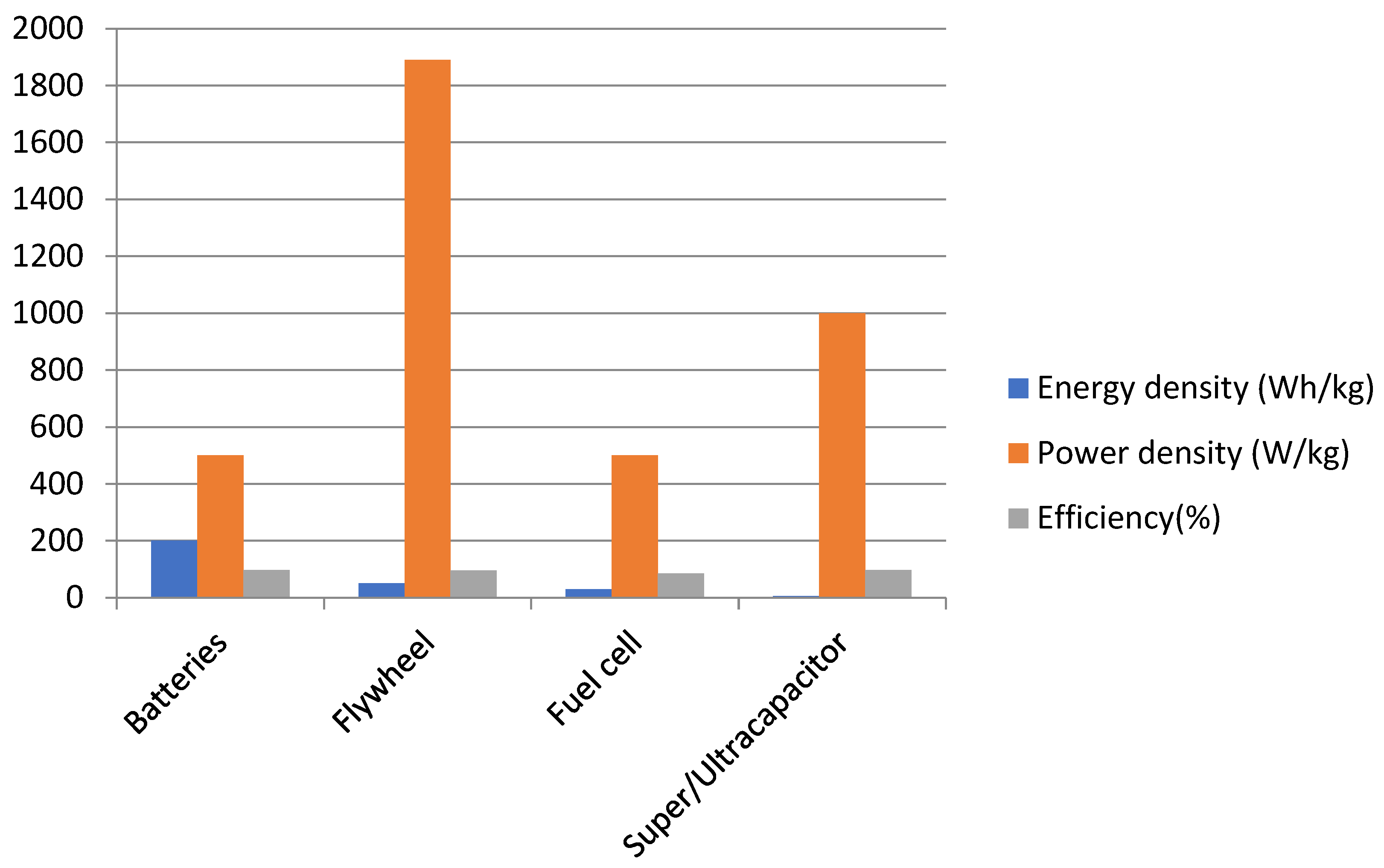
3.2. Super-Capacitor/Ultra-Capacitor

SCs are high capacitance capacitors that offer many outstanding features such as high power density, long life-cycle, wide operating temperature range, and fast charging/discharging response. SC works on the principle of storing energy on two parallel electrodes separated by an insulator.
As there are no chemical variations on the electrodes, SCs have a long lifetime. Although SC offers better performance in most of the terms, it cannot be used as the main ESS since its energy density is relatively low. Likewise, as SCs technology was only recently developed, they are not as reliable as conventional batteries.

3.3. Fuel Cell

A fuel cell (FC) is another clean energy source and generates electricity based on the reaction in the electrolyte with fuel and oxidant on the anode and cathode, respectively. Generally, the reactants and their product flow in and out of the cell during the electricity generation process. As long as the flow of the reactant is maintained, FC is capable of generating electricity. FC offers numerous advantages: higher fuel-to-electrical energy conversion efficiency, noiseless operation, zero or very low emission, waste heat recoverability, fuel flexibility, durability, and reliability. FCs employ different combinations of fuels (hydrogen, hydrocarbons, and alcohols) and oxidants (chlorine and chlorine dioxide). Among various fuels, hydrogen is an ideal nonpollutant which possesses higher energy density. Unlike electrochemical batteries, FC reactants must be restocked prior to usage. FCs find limited application in EVs due to longtime constants, i.e., high response time.

3.4. Flywheel Energy Storage System

A clever way to store electricity in the form of kinetic energy is through the use of flywheels. According to the proposed method, excess electricity can be saved by powering a motor that spins a flywheel at a high rate of speed to store kinetic energy. Because it is levitated in an evacuated chamber using magnets and very effective bearings, the flywheel moves effortlessly. The flywheel’s momentum, which is the stored kinetic energy, can activate an electricity generator as another component of the system to generate power. The flywheel is supported using magnetic levitation to reduce mechanical wear. When compared to other storage options for electric vehicles, flywheels have many benefits. For example, they are lighter, quicker, and more effective at absorbing energy from regenerative braking. They are also quicker at supplying a large amount of energy in a short period of time when rapid acceleration is required. The performance comparison of the flywheel energy storage system against various ESSs is illustrated in Figure 7.

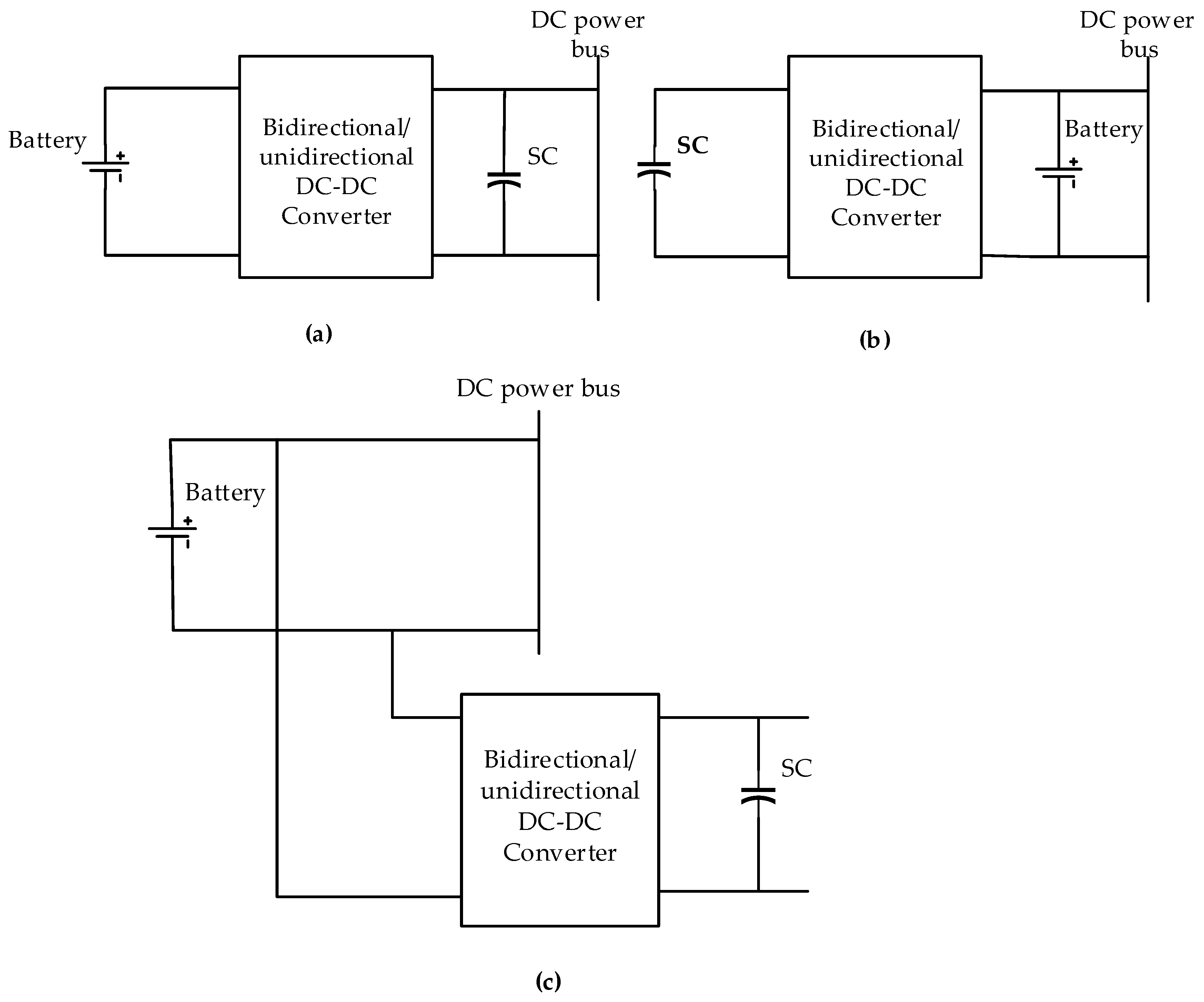
3.5. Hybrid Energy Storage System (HESS)

As a single energy storage element may not meet the entire electric energy range of an EV, HESSs have evolved. Complementary features of different ESSs, such as batteries, SCs, and FC, can be integrated and utilized as HESS. HESS offers combined advantages of individual ESSs: high power densities of SC effectively harness the kinetic energy during braking; SCs assist the batteries during peak power demand aiding in extending battery life and improving vehicle acceleration; furthermore, as the braking energy is fruitfully saved, the driving range of EVs is considerably increased. Overall, HESS utilization offers several benefits, such as efficient RB, battery safety, and improved vehicle acceleration. The different passive and active HESS for EV applications and their purpose are summarized in Table 8. A switching control strategy based on hysteresis and logic switching is proposed to manage the power flow in UC using a bidirectional DC-DC converter [74]. An active HESS with a bidirectional non-isolated multi-input converter is proposed in ref. [75] for energy regulation in the battery and SC. The uniqueness of the proposed topology is that the converter requires only one extra active switch and results in a reduced number of elements. Likewise, a bidirectional interleaved buck–boost converter is designed in ref. [76] to control the charging and to discharge batteries. The converter’s controller adopts SMC employing a hyperbolic tangent function to reduce the current ripple. The difference between active and passive ESS is demonstrated in Table 9.

4. Power Converter Topologies

The application of power electronics is expanding day by day with the advancement in semiconductor technologies, especially in the fields primarily concerned with transforming power from one form to another and regulating different voltage levels. As depicted in Figure 1, different configurations of PECs are employed in EV applications as chargers (DC-DC/AC-DC), active HESS energy regulators (DC-DC), and machine drivers (DC-AC). The purpose of PECs and the different topologies employed in EV application is detailed in this section.

4.1. Charger

With the emerging application of EVs, the design of efficient and high-quality ESS chargers has become a vital research topic. A charger is used to recharge the battery pack either from solar power using a DC-DC converter or from the grid using an AC-DC converter. Additionally, the charger (DC-DC) may be the one associated with the fuel stack and hydrogen tank. Various topologies for both configurations are discussed in this section.

4.1.1. DC-DC Converters

Depending on the application, different DC-DC converter topologies are reported in the literature as chargers which perform the basic boost, buck, and buck–boost operation.

Boost Converter

A new multi-input multi-output DC-DC boost converter for hybridizing two different power sources, such as a dc power supply and a battery for EV application, is proposed in ref. [85]. The converter is designed to have multiple outputs with varying voltage levels and also controls the power flow between sources and the load. The controller is framed in such a way that in the battery discharging mode, both input sources supply power to the EV, whereas in the battery charging mode, one of the input sources (DC supply) supplies the loads as well as charges the battery. In refs. [86,87,88,89], a stackable switched converter for an EV powered by FCs is implemented with improved particle swarm optimization (IPSO) and adaptive cuckoo search optimization (ACSO) control techniques for MPPT. It is reported that ACSO provides a better response compared to IPSO.

Buck Converter

An integrated synchronous buck converter is proposed to independently regulate multiple outputs of the auxiliary power supply system with minimum switching components compared to traditional buck converters [90]. Single input multiple output buck converters are proposed in ref. [91].

Buck-Boost Converter

Two configurations of bidirectional DC-DC converters, i.e., cascaded buck–boost and non-isolated capacitor and inductor in the middle, are proposed for the charging application [92]. The proposed converter performance is validated in terms of device requirements, switching device rating, and control strategy. Likewise, a bidirectional DC-DC converter with a variable inductor is implemented in refs. [93,94] to enhance the performance under load variation. In this topology, extra winding is added to the conventional topology to inject the current and in turn to regulate the magnetic core permeability C-Chopper. The performance of all types of converters is provided in Table 10.

4.1.2. AC-DC Converters

In ref. [95], an AC-DC battery charger with an active cell is employed to efficiently achieve the power factor correction. The converter employs zero voltage and current switching to minimize the switching losses. The proposed controller design ensures the unity power factor as well as soft switching operations for the prevailing load conditions from light to full load. A novel integrated converter is proposed in ref. [96] to enable the battery to charge either from the utility grid or a solar photovoltaic system. The proposed converter utilizes a lesser number of components, incorporates power factor correction evading the current sensor, and the same converter can be used to operate in all modes such as charging, propulsion, and RB.
In ref. [97], a new configuration is presented for an onboard battery charger with the symmetrical six-phase open-end winding machine, 12-leg inverter, and a DC-DC converter. The proposed system possesses the advantage of high power density, unity power factor operation, high filtering, and fault-tolerant capability. An electrolytic capacitor with less onboard charger is suggested in ref. [98], which employs the cascade structure of a constant frequency resonant converter with a very simple control algorithm to employ harmonic regulation, charging control, and power factor correction. In ref. [99], a new configuration, namely a lands-man power factor correction converter cascaded with a flyback converter, is designed to charge the battery initially under constant current mode and later under constant voltage mode. The proposed method ensures robust regulation of DC-link voltage, unity power factor operation, improved power quality, low device stress, and low input and output current ripple.

4.2. Machine Driver: Inverter

A DC-AC converter uses the high voltage of the battery to propulse the electric motor. The inverter can convert energy from the high-voltage battery to multiphase AC current to drive the traction motor in an EV application.

4.2.1. Basic Level Inverter

A three-phase inverter employing GaN MOSFET as a switching device with predictive current control is investigated in ref. [100]. The performance of the proposed system is validated against the conventional one in terms of switching losses, efficiency, and driving range. With the objective of improving the efficiency of the powertrain, an improved control strategy is proposed for the quasi-Z-source inverter-based PMSM drive [101]. In ref. [102], to achieve a long-driving range, a new distributed three single-phase inverter is proposed for open-end winding IM. The topology eliminates the requirement of the parallel combination of batteries and, in turn, reduces the rise in circulation current. A detailed investigation is carried out in ref. [103] to study the nonlinearities of the inverters with silicon carbide MOSFETs and silicon IGBT as a switching devices. System parameters such as voltage drops, dead time, output capacitance, switching time delay, and voltage overshoot of both the power devices are studied. In ref. [104], a three-level neutral-point clamped inverter is employed to control the drive with a new switching sequence for SV-PWM. Unlike the conventional technique, with the proposed topology, the number of switching sequences is reduced, and the voltage difference between two dc-link capacitors is maintained at the preferred level. An air-cooled SiC inverter with the improvement in the power unit, DC-link capacitor, and heat sink level is implemented by incorporating a multi-physics model, DC-link capacitor design, and electro-thermal evaluation techniques, respectively.

4.2.2. Multilevel Inverter

A cascaded H-bridge multilevel boost inverter without an inductor is proposed in ref. [105]. Generally, every H-bridge requires a DC power source; however, in the proposed method, the H-bridge in series with each inverter leg uses a capacitor as the power supply. To attain the battery balance discharging and motor speed regulation, a cascaded multilevel inverter is proposed in ref. [106]. An asymmetrical cascaded H- bridge inverter is presented in ref. [107] to mitigate the problem of conventional ones by functioning some of the auxiliary bridges as active series filters.
The proposed topology requires only one DC source and can produce the maximum output voltage levels of 27. A comparative analysis of symmetrical and asymmetrical cascaded multilevel inverters is detailed in ref. [108] with several findings such as the way to increase the voltage levels, reduce the redundancy level, and achieve the lowest distortion.

4.2.3. Dual Inverter

A dual voltage source inverter and a modified SVM controller design are proposed with the intention of reducing the switching losses [109]. The proposed topology evades the necessity of a DC-DC converter which is an unavoidable component in the conventional structure of the propulsion unit. The performance of the inverter is summarized in Table 11 and Figure 8.

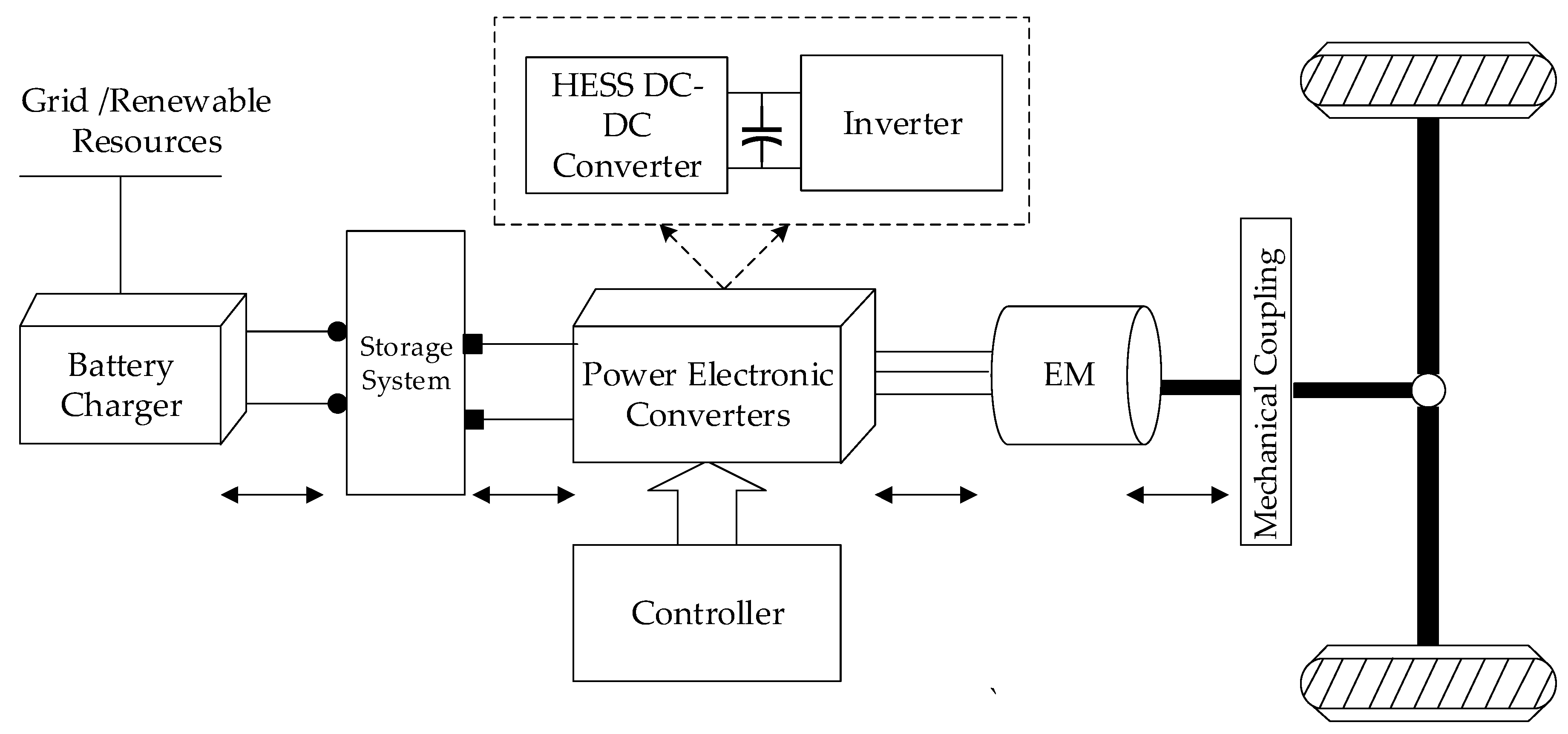
4.3. Active HESS Energy Manager

The onboard ESS is expected to possess high energy capacity and power capability to sustain long-distance driving and to enable sharp accelerations and RB. To sustain high power loads, one possible solution is to deploy SCs as the second energy storage device in addition to batteries. Such HESS comprises components such as a battery pack, SC pack, and one/multiple DC-DC converter(s). Generally, a DC-DC converter is employed to interface the battery and SC and to manage the energy flow between them. An online EMS with a variable perception horizon based on both neural network and rule-based techniques is proposed in ref. [79] to optimize the operating cost of HESS due to their improved performances compared with the sole energy source in system efficiency and battery lifetime. A real-time EMC strategy based on a combination of the wavelet transform, neural network, and fuzzy logic is proposed in ref. [80] to improve EV performance. In ref. [81], a power control framework is formulated with two stages, one for computing the SC reference voltage, and the other for optimizing the power flowing through the HESS. The sizing of HESS components is presented in ref. [77] and ref. [78] to minimize the financial costs over the vehicle lifetime considering various factors such as driving cycle and range, converter’s efficiency, nominal bus voltage, and HESS topology. Similarly, the optimal sizing of HESSs, considering the energy management strategy based on frequency-separation, is presented in ref. [82]. The different types of topologies in HESS are provided in Figure 9.
Based on the literature review, the state of the art of real-time use cases are presented in Table 12.

5. Selection of Sub-Systems
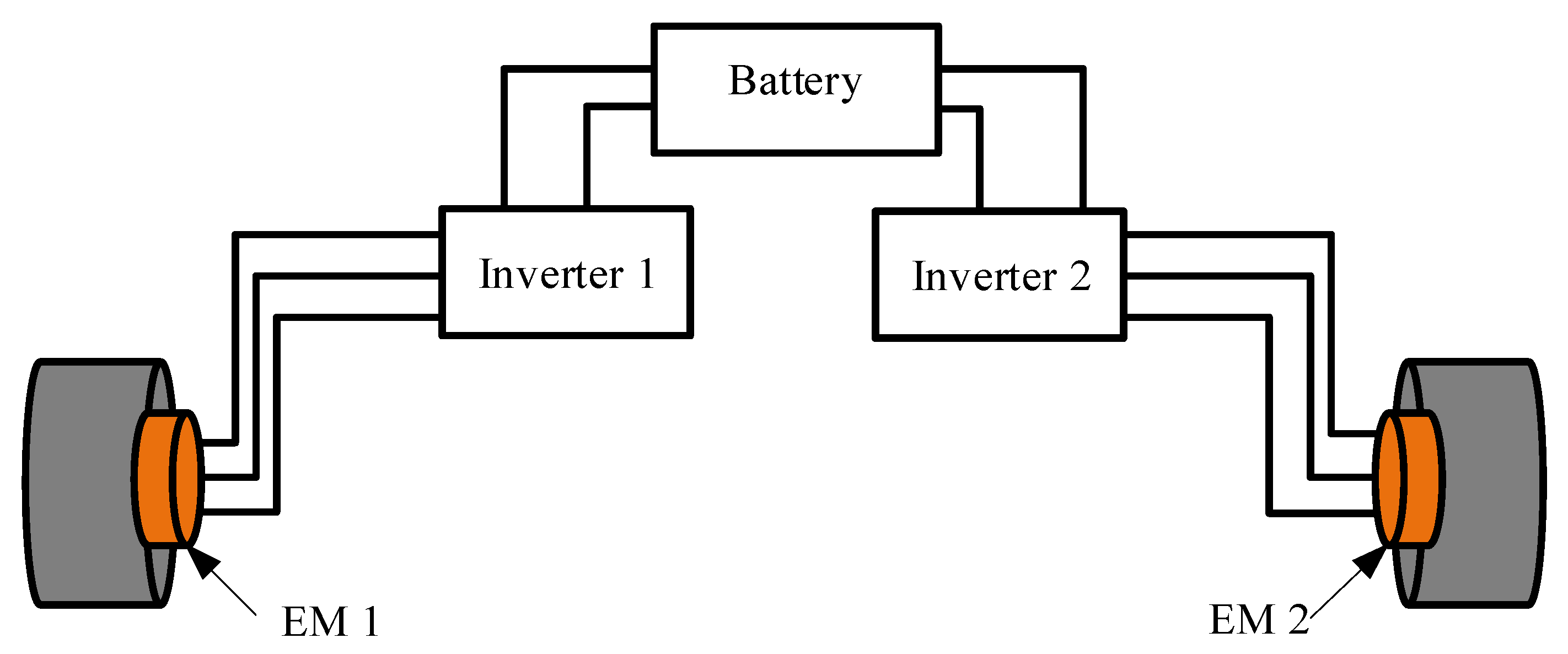
Based on the survey, the basic, additional, and advanced control techniques needed for PECs used in EVs, such as charger, active HSSS energy manager, and machine driver, are summarized in this section. The control techniques are listed for both three- and four-wheeler EVs.

5.1. Four-Wheeler

Among different passenger transportation EVs, four wheelers have the highest demand. This type of vehicle generally employs machine drives such as IM, PMSM, SRM, and SyncRM, as indicated in the previous section. Irrespective of the machines, the control techniques employed for EV application remain almost the same as illustrated in Figure 10, which includes the same basic, additional, and advanced control as that of BLDC-based drive. The advanced control also includes disturbance rejection and FTC. The control of PEC’s charger and active HESS energy manager remains the same as the three-wheeler structure.

5.2. Three-Wheeler

The most suitable drives for three-wheeler propulsion systems, such as BLDC and PMSM’s control strategies, are highlighted. The strategies include basic controls such as speed, torque, and current control during motoring mode and DC bus voltage regulation during RB mode. The drive control also includes additional control such as sensorless estimation of motor flux, speed, and rotor position. Supplementary controls such as torque limiter and MTPA are also reported in the literature. Likewise, advanced control techniques such as the minimization of torque ripple and EMI are essential. While moving to power electronic converter topology corresponding to charging, i.e., the DC-DC converter controller is basically employed with the MPPT technique if the EV is powered from solar energy, or else, the controller is employed with voltage regulation in case of grid support. Similarly, the PEC used to manage the AHESS employs basic and advanced control of EMC and voltage regulation, respectively.

5.3. In-Wheel Motor EV

High-speed electric machine is a workable technique for boosting the BEVs powertrain drive power density even though the approach burdens the transmission system and its design. The alternative technique to the high-speed electric machines path for BEV application is direct drive in-wheel electric machines. The main advantage of the in-wheel machine is improved space for passengers and the battery pack, separate motor control for each wheel providing better ride and performance, and the elimination of mechanical gears and transmission. The different types of in-wheel machines used in BEVs are PM hybrid, axial flux PM, and BLDC. The structure of the in-wheel motor is provided in Figure 11.

6. Conclusions

Due to the depletion of fossil fuel resources and the volatility of oil prices, the electrification of vehicles is emerging as an alternative solution to improve the efficiency of existing transportation technologies. This article investigated the key structures and control techniques of various components of EV propulsion systems. The detailed study of system components such as the battery charger, active HESS manager, machine driver, and its corresponding control strategies are analyzed. The aim of this article is to offer a clear roadmap of the existing components and the technologies of three- and four-wheeler EVs.

Author Contributions

Conceptualization, E.S. and V.R.; methodology, E.S.; software, E.S.; validation, V.R.; formal analysis, V.R.; investigation, V.R.; resources, E.S.; data curation, E.S.; writing—original draft preparation, E.S.; writing—review and editing, V.R.; visualization, E.S.; supervision, V.R.; project administration, V.R. All authors have read and agreed to the published version of the manuscript.

Funding

This research received no external funding.

Data Availability Statement

Not applicable.

Acknowledgments

The authors would like to thank Vellore Institute of Technology, Vellore for the support.

Conflicts of Interest

The authors declare no conflict of interest.

References

  1. Needell, Z.A.; McNerney, J.; Chang, M.T.; Trancik, J.E. Potential for widespread electrification of personal vehicle travel in the United States. Nat. Energy 2016, 1, 16112. [Google Scholar] [CrossRef] [Green Version]
  2. Rind, S.J.; Ren, Y.; Hu, Y.; Wang, J.; Jiang, L. Configurations and control of traction motors for electric vehicles: A review. Chin. J. Electr. Eng. 2017, 3, 1–17. [Google Scholar] [CrossRef]
  3. Spichartz, P.; Bokker, T.; Sourkounis, C. Comparison of electric vehicles with single drive And Four Wheel Drive System Concerning Regenerative Braking. In Proceedings of the 2017 Twelfth International Conference on Ecological Vehicles and Renewable Energies (EVER), Monte Carlo, Monaco, 11–13 April 2017; IEEE: Piscataway, NJ, USA, 2017; pp. 1–7. [Google Scholar]
  4. Buekers, J.; Van Holderbeke, M.; Bierkens, J.; Panis, L.I. Health and environmental benefits related to electric vehicle introduction in EU countries. Transp. Res. Part D Transp. Environ. 2014, 33, 26–38. [Google Scholar] [CrossRef]
  5. Bilgin, B.; Magne, P.; Malysz, P.; Yang, Y.; Pantelic, V.; Preindl, M.; Korobkine, A.; Jiang, W.; Lawford, M.; Emadi, A. Making the Case for Electrified Transportation. IEEE Trans. Transp. Electrif. 2015, 1, 4–17. [Google Scholar] [CrossRef]
  6. Broadbent, G.H.; Metternicht, G.; Drozdzewski, D. An Analysis of Consumer Incentives in Support of Electric Vehicle Uptake: An Australian Case Study. World Electr. Veh. J. 2019, 10, 11. [Google Scholar] [CrossRef] [Green Version]
  7. Rajashekara, K. Present Status and Future Trends in Electric Vehicle Propulsion Technologies. IEEE J. Emerg. Sel. Top. Power Electron. 2013, 1, 3–10. [Google Scholar] [CrossRef]
  8. Liu, C.; Chau, K.T.; Lee, C.H.T.; Song, Z. A Critical Review of Advanced Electric Machines and Control Strategies for Electric Vehicles. Proc. IEEE 2021, 109, 1004–1028. [Google Scholar] [CrossRef]
  9. Emadi, A.; Lee, Y.J.; Rajashekara, K. Power Electronics and Motor Drives in Electric, Hybrid Electric, and Plug-In Hybrid Electric Vehicles. IEEE Trans. Ind. Electron. 2008, 55, 2237–2245. [Google Scholar] [CrossRef]
  10. De Klerk, M.L.; Saha, A.K. A Comprehensive Review of Advanced Traction Motor Control Techniques Suitable for Electric Vehicle Applications. IEEE Access 2021, 9, 125080–125108. [Google Scholar] [CrossRef]
  11. Kamrul, M.; Habib, A.K.M.A.; Motakabber, S.M.A.; Islam, S. Review of Electric Vehicle Energy Storage and Management System: Standards, Issues, and Challenges. J. Energy Storage 2021, 41, 102940. [Google Scholar]
  12. Wassiliadis, N.; Schneider, J.; Frank, A.; Wildfeuer, L.; Lin, X.; Jossen, A.; Lienkamp, M. Review of fast charging strategies for lithium-ion battery systems and their applicability for battery electric vehicles. J. Energy Storage 2021, 44, 103306. [Google Scholar] [CrossRef]
  13. Yilmaz, M.; Krein, P.T. Review of Battery Charger Topologies, Charging Power Levels, and Infrastructure for Plug-In Electric and Hybrid Vehicles. IEEE Trans. Power Electron. 2013, 28, 2151–2169. [Google Scholar] [CrossRef]
  14. Bu, F.; Liu, H.; Huang, W.; Hu, Y.; Degano, M.; Gerada, C.; Rajashekara, K. Induction-Machine-Based Starter/Generator Systems: Techniques, Developments, and Advances. IEEE Ind. Electron. Mag. 2020, 14, 4–19. [Google Scholar] [CrossRef]
  15. Rivière, N.; Volpe, G.; Leonardo, L. Di Design Analysis of a High Speed Copper Rotor Induction Motor for a Traction Application. In Proceedings of the 2019 IEEE International Electric Machines & Drives Conference (IEMDC), San Diego, CA, USA, 12–15 May 2019; pp. 1024–1031. [Google Scholar]
  16. Saad, K.; Abdellah, K.; Ali, T.B. Advanced fault-tolerant control of multiphase induction motor drives in EV. In Proceedings of the 2019 1st International Conference on Sustainable Renewable Energy Systems and Applications (ICSRESA), Tebessa, Algeria, 4–5 December 2019; IEEE: Piscataway, NJ, USA, 2019; pp. 1–5. [Google Scholar]
  17. Quintero-Manríquez, E.; Sanchez, E.N.; Antonio-Toledo, M.E.; Muñoz, F. Neural control of an induction motor with regenerative braking as electric vehicle architecture. Eng. Appl. Artif. Intell. 2021, 104, 104275. [Google Scholar] [CrossRef]
  18. Han, P.; Cheng, M.; Chen, Z. Dual-Electrical-Port Control of Cascaded Doubly-Fed Induction Machine for EV/HEV Applications. IEEE Trans. Ind. Appl. 2016, 53, 1390–1398. [Google Scholar] [CrossRef]
  19. Su, J.; Gao, R.; Husain, I. Model Predictive Control Based Field-Weakening Strategy for Traction EV Used Induction Motor. IEEE Trans. Ind. Appl. 2017, 54, 2295–2305. [Google Scholar] [CrossRef]
  20. Tabbache, B.; Rizoug, N.; El, M.; Benbouzid, H.; Member, S. A Control Reconfiguration Strategy for Post-Sensor FTC in Induction Motor-Based EVs. IEEE Trans. Veh. Technol. 2013, 62, 965–971. [Google Scholar] [CrossRef] [Green Version]
  21. Yu, J.; Pei, W.; Zhang, C. A Loss-Minimization Port-Controlled Hamilton Scheme of Induction Motor for Electric Vehicles. IEEE/ASME Trans. Mechatron. 2014, 20, 2645–2653. [Google Scholar] [CrossRef]
  22. Attaianese, C.; Di Monaco, M.; Spina, I.; Tomasso, G. A Variational Approach to MTPA Control of Induction Motor for EVs Range Optimization. IEEE Trans. Veh. Technol. 2020, 69, 7014–7025. [Google Scholar] [CrossRef]
  23. Haddoun, A.; El, M.; Benbouzid, H.; Member, S.; Diallo, D.; Member, S.; Abdessemed, R.; Ghouili, J.; Srairi, K. A Loss-Minimization DTC Scheme for EV Induction Motors. IEEE Trans. Veh. Technol. 2007, 56, 81–88. [Google Scholar] [CrossRef] [Green Version]
  24. Naganathan, P.; Srinivas, S. MTPA Associated DTC Methodologies for Enhanced Performance and Energy Savings in Electric Vehicle Mobility With Induction Motor Drive. IEEE Trans. Transp. Electrif. 2022, 8, 1853–1862. [Google Scholar] [CrossRef]
  25. Quintero-manríquez, E.; Sanchez, E.N. Real-Time Direct Field-Oriented and Second Order Sliding Mode Controllers of Induction Motor for Electric Vehicles Applications. In Proceedings of the 2015 10th System of Systems Engineering Conference, San Antonio, TX, USA, 17–20 May 2015; pp. 220–225. [Google Scholar]
  26. Iffouzar, K.; Amrouche, B.; Cherif, T.O.; Benkhoris, M.-F.; Aouzellag, D.; Ghedamsi, K. Improved direct field oriented control of multiphase induction motor used in hybrid electric vehicle application. Int. J. Hydrog. Energy 2017, 42, 19296–19308. [Google Scholar] [CrossRef]
  27. Zhang, X. Sensorless Induction Motor Drive Using Indirect Vector Controller and Sliding-Mode Observer for Electric Vehicles. IEEE Trans. Veh. Technol. 2013, 62, 3010–3018. [Google Scholar] [CrossRef]
  28. Muduli, U.R.; Beig, A.R.; Behera, R.K.; Al Jaafari, K.; Alsawalhi, J.Y. Predictive Control With Battery Power Sharing Scheme for Dual Open-End-Winding Induction Motor Based Four-Wheel Drive Electric Vehicle. IEEE Trans. Ind. Electron. 2022, 69, 5557–5568. [Google Scholar] [CrossRef]
  29. Lu, C.; Ferrari, S.; Pellegrino, G. Two Design Procedures for PM Synchronous Machines for Electric Powertrains. IEEE Trans. Transp. Electrif. 2017, 3, 98–107. [Google Scholar] [CrossRef] [Green Version]
  30. Chen, Z.; Li, G. A V Type Permanent Magnet Motor Simulation Analysis and Prototype Test for Electric Vehicle. IEEE Access 2019, 7, 174839–174846. [Google Scholar] [CrossRef]
  31. Cao, L.; Member, S.; Chau, K.T.; Lee, C.H.T.; Member, S.; Wang, H.; Member, S. A Double-Rotor Flux-Switching. IEEE Trans. Ind. Electron. 2021, 68, 1004–1015. [Google Scholar] [CrossRef]
  32. Ahn, K.; Bayrak, A.E.; Papalambros, P.Y. Electric Vehicle Design Optimization: Integration of a High-Fidelity Interior-Permanent-Magnet Motor Model. IEEE Trans. Veh. Technol. 2015, 64, 3870–3877. [Google Scholar] [CrossRef]
  33. Miyama, Y.; Hazeyama, M.; Hanioka, S.; Watanabe, N.; Daikoku, A.; Inoue, M. PWM Carrier Harmonic Iron Loss Reduction Technique of Permanent-Magnet Motors for Electric Vehicles. IEEE Trans. Ind. Appl. 2016, 52, 2865–2871. [Google Scholar] [CrossRef]
  34. Lu, Y.; Jiang, Z.; Chen, C.; Zhuang, Y. Energy efficiency optimization of field-oriented control for PMSM in all electric system. Sustain. Energy Technol. Assess. 2021, 48, 101575. [Google Scholar] [CrossRef]
  35. Ramesh, P.; Umavathi, M.; Bharatiraja, C.; Ramanathan, G.; Athikkal, S. Materials Today: Proceedings Development of a PMSM Motor Field-Oriented Control Algorithm for Electrical Vehicles. Mater. Today Proc. 2022, 65, 176–187. [Google Scholar] [CrossRef]
  36. Zhang, Z.; Ma, R.; Wang, L.; Zhang, J. Novel PMSM Control for Anti-Lock Braking Considering Transmission Properties of the Electric Vehicle. IEEE Trans. Veh. Technol. 2018, 67, 10378–10386. [Google Scholar] [CrossRef]
  37. Wei, J.; Member, S.; Kong, X.; Tao, W.; Zhang, Z.; Member, S.; Zhou, B. The Torque Ripple Optimization of Open-Winding Permanent Magnet Synchronous Motor with Direct Ratio Range. IEEE Trans. Power Electron. 2022, 37, 7156–7168. [Google Scholar] [CrossRef]
  38. Arias, A.; Ibarra, E.; Trancho, E.; Griñó, R.; Kortabarria, I.; Caum, J. Comprehensive high speed automotive SM-PMSM torque control stability analysis including novel control approach. Int. J. Electr. Power Energy Syst. 2020, 109, 423–433. [Google Scholar] [CrossRef]
  39. Li, L.; Li, X.; Wang, X.; Song, J.; He, K.; Li, C. Analysis of downshift’s improvement to energy efficiency of an electric vehicle during regenerative braking. Appl. Energy 2016, 176, 125–137. [Google Scholar] [CrossRef]
  40. Choo, K.-M.; Won, C.-Y. Design and Analysis of Electrical Braking Torque Limit Trajectory for Regenerative Braking in Electric Vehicles with PMSM Drive Systems. IEEE Trans. Power Electron. 2020, 35, 13308–13321. [Google Scholar] [CrossRef]
  41. Itani, K.; De Bernardinis, A.; Khatir, Z.; Jammal, A.; Oueidat, M. Regenerative Braking Modeling, Control, and Simulation of a Hybrid Energy Storage System for an Electric Vehicle in Extreme Conditions. IEEE Trans. Transp. Electrif. 2016, 2, 465–479. [Google Scholar] [CrossRef]
  42. Fajri, P.; Lee, S.; Member, S.; Anand, V.; Prabhala, K.; Member, S.; Ferdowsi, M. Modeling and Integration of Electric Vehicle Regenerative and Friction Braking for Motor/Dynamometer Test Bench Emulation. IEEE Trans. Veh. Technol. 2016, 65, 4264–4273. [Google Scholar] [CrossRef]
  43. Qiu, C.; Wang, G. New evaluation methodology of regenerative braking contribution to energy efficiency improvement of electric vehicles. Energy Convers. Manag. 2016, 119, 389–398. [Google Scholar] [CrossRef]
  44. Gao, S.; Wei, Y.; Zhang, D.; Qi, H.; Wei, Y.; Yang, Z. Model-Free Hybrid Parallel Predictive Speed Control Based On Ultralocal Model of PMSM for Electric Vehicles. IEEE Trans. Ind. Electron. 2022, 69, 9739–9748. [Google Scholar] [CrossRef]
  45. Meesala, E.K.; Athikkal, S.; Prasad, A. Modified Direct Torque Control of PMSM Drive for Electric Vehicle Application. In Proceedings of the 2021 IEEE Madras Section Conference, Chennai, India, 27–28 August 2021. [Google Scholar]
  46. Sreejith, R. Intelligent Nonlinear Sensorless Predictive Field Oriented Control of PMSM Drive for Three Wheeler Hybrid Solar PV-Battery Electric Vehicle. In Proceedings of the 2019 IEEE Transportation Electrification Conference and Expo (ITEC), Detroit, MI, USA, 19–21 June 2019. [Google Scholar]
  47. Li, G.; Hu, J.; Li, Y.; Zhu, J. An Improved Model Predictive Direct Torque Control Strategy for Reducing Harmonic Currents and Torque Ripples of Five-Phase Permanent Magnet Synchronous Motors. IEEE Trans. Ind. Electron. 2019, 66, 5820–5829. [Google Scholar] [CrossRef]
  48. Abdelrauf, A.A.; Galea, M. Model Predictive Control Based PID Controller for PMSM for Propulsion Systems. In Proceedings of the 2018 IEEE International Conference on Electrical Systems for Aircraft, Railway, Ship Propulsion and Road Vehicles & International Transportation Electrification Conference (ESARS-ITEC), Nottingham, UK, 7–9 November 2018; pp. 7–13. [Google Scholar]
  49. Zhu, J.; Cheng, K.W.E.; Xue, X.; Zou, Y. Design of a New Enhanced Torque In-Wheel Switched Reluctance Motor With Divided Teeth for Electric Vehicles. IEEE Trans. Magn. 2017, 53, 1–4. [Google Scholar] [CrossRef]
  50. Chen, H.; Yan, W.; Gu, J.J.; Sun, M. Multiobjective Optimization Design of a Switched Reluctance Motor for Low-Speed Electric Vehicles With a Taguchi–CSO Algorithm. IEEE/ASME Trans. Mechatron. 2018, 23, 1762–1774. [Google Scholar] [CrossRef]
  51. Inderka, R.B.; Menne, M.; Doncker, R.W.A.A. De Vehicle Applications. IEEE Trans. Ind. Electron. 2002, 49, 48–53. [Google Scholar] [CrossRef]
  52. Sun, X.; Diao, K.; Lei, G.; Guo, Y.; Zhu, J. Direct Torque Control Based on a Fast Modeling Method for a Segmented-Rotor Switched Reluctance Motor in HEV Application. IEEE J. Emerg. Sel. Top. Power Electron. 2021, 9, 232–241. [Google Scholar] [CrossRef]
  53. Schulz, S.; Rahman, K. High-performance digital pi current regulator for ev switched reluctance motor drives. IEEE Trans. Ind. Appl. 2003, 39, 1118–1126. [Google Scholar] [CrossRef]
  54. Zhu, Y.; Wu, H.; Zhen, C. Regenerative braking control under sliding braking condition of electric vehicles with switched reluctance motor drive system. Energy 2021, 230, 120901. [Google Scholar] [CrossRef]
  55. Xue, X.D.; Cheng, K.W.E.; Lin, J.K.; Zhang, Z.; Luk, K.F.; Ng, T.W.; Cheung, N.C. Optimal Control Method of Motoring Operation for SRM Drives in Electric Vehicles. IEEE Trans. Veh. Technol. 2010, 59, 1191–1204. [Google Scholar] [CrossRef]
  56. Villet, W.T.; Member, S.; Kamper, M.J.; Member, S. Variable-Gear EV Reluctance Synchronous Motor Drives—An Evaluation of Rotor Structures for Position-Sensorless Control. IEEE Trans. Ind. Electron. 2014, 61, 5732–5740. [Google Scholar] [CrossRef]
  57. Bianchi, N.; Bolognani, S.; Carraro, E.; Castiello, M.; Fornasiero, E. Reluctance Motors. IEEE Trans. Ind. Appl. 2016, 52, 4762–4769. [Google Scholar] [CrossRef]
  58. Taghavi, S.; Pillay, P. A Sizing Methodology of the Synchronous Reluctance Motor for Traction Applications. IEEE J. Emerg. Sel. Top. Power Electron. 2014, 2, 329–340. [Google Scholar] [CrossRef]
  59. Boldea, I.; Pitic, C.; Lascu, C.; Andreescu, G.-D.; Tutelea, L.; Blaabjerg, F.; Sandholdt, P. DTFC-SVM motion-sensorless control of a PM-assisted reluctance synchronous machine as starter-alternator for hybrid electric vehicles. IEEE Trans. Power Electron. 2006, 21, 711–719. [Google Scholar] [CrossRef]
  60. Niazi, P.; Toliyat, H.A.; Member, S.; Goodarzi, A.; Member, S.; Recently, A. Robust Maximum Torque per Ampere (MTPA) Control of PM-Assisted SynRM for Traction Applications. IEEE Trans. Veh. Technol. 2007, 56, 1538–1545. [Google Scholar] [CrossRef]
  61. Damiano, A.; Floris, A.; Fois, G.; Marongiu, I.; Porru, M.; Serpi, A. Design of a High-Speed Ferrite-Based Brushless DC Machine for Electric Vehicles. IEEE Trans. Ind. Appl. 2017, 53, 4279–4287. [Google Scholar] [CrossRef] [Green Version]
  62. Naseri, F.; Farjah, E.; Ghanbari, T. An Efficient Regenerative Braking System Based on Battery/Supercapacitor for Electric, Hybrid and Plug-In Hybrid Electric Vehicles with BLDC Motor. IEEE Trans. Veh. Technol. 2016, 66, 3724–3738. [Google Scholar] [CrossRef]
  63. Nian, X.; Peng, F.; Zhang, H. Regenerative Braking System of Electric Vehicle Driven by Brushless DC Motor. IEEE Trans. Ind. Electron. 2014, 61, 5798–5808. [Google Scholar] [CrossRef]
  64. Pan, C.; Chen, L.; Chen, L.; Jiang, H.; Li, Z.; Wang, S. Research on motor rotational speed measurement in regenerative braking system of electric vehicle. Mech. Syst. Signal Process. 2016, 66–67, 829–839. [Google Scholar] [CrossRef]
  65. Olson, J.B.; Sexton, E.D. Operation of Lead-Acid Batteries for HEV Applications. In Proceedings of the Fifteenth Annual Battery Conference on Applications and Advances, Long Beach, CA, USA, 11–14 January 2000; pp. 205–210. [Google Scholar]
  66. Caumont, O.; Le Moigne, P.; Rombaut, C.; Muneret, X.; Lenain, P. Energy gauge for lead-acid batteries in electric vehicles. IEEE Trans. Energy Convers. 2000, 15, 354–360. [Google Scholar] [CrossRef]
  67. Weiss, H.; Winkler, T.; Ziegerhofer, H. Large Lithium-Ion Battery-Powered Electric Vehicles—From Idea to Reality; IEEE: New York, NY, USA, 2018. [Google Scholar]
  68. Xiao, L.; Haitao, X.; Dgguhvv, E. Cycle life prediction method of lithium ion batteries for new energy electric vehicles. In Proceedings of the 2021 International Conference of Social Computing and Digital Economy (ICSCDE), Chongqing, China, 28–29 August 2021; IEEE: Piscataway, NJ, USA, 2021; pp. 108–112. [Google Scholar]
  69. Manzoni, R. Sodium Nickel Chloride Batteries in Transportation Applications. In Proceedings of the 2015 International Conference on Electrical Systems for Aircraft, Railway, Ship Propulsion and Road Vehicles (ESARS), Aachen, Germany, 3–5 March 2015; pp. 1–6. [Google Scholar]
  70. Reisner, D.; Klein, M. Bipolar nickel-metal hydride battery for hybrid vehicles. IEEE Aerosp. Electron. Syst. Mag. 1994, 9, 24–28. [Google Scholar] [CrossRef]
  71. Jiayuan, W.; Zechang, S.; Xuezhe, W.; Basics, A. Performance and Characteristic Research in LiFePO4 Battery for Electric Vehicle Applications. In Proceedings of the 2009 IEEE Vehicle Power and Propulsion Conference, Dearborn, MI, USA, 7–10 September 2009; pp. 1657–1661. [Google Scholar]
  72. Disosway, M. Development of High Power Nickel-Cadmium Batteries for Hybrid Vehicles. In Proceedings of the Thirteenth Annual Battery Conference on Applications and Advances; Long Beach, CA, USA, 16 January 1998, pp. 19–23.
  73. Squiller, D.; Brody, R.; Centre, T.; Diego, S. Nickel-Zinc Batteries for Hybrid Electric Vehicles and Stationary Storage. Nano Sci. Technol. Inst. 2011, 1, 690–693. [Google Scholar]
  74. Mendoza-Torres, A.; Visairo, N.; Nuñez, C.; Armenta, J.; Rodríguez, E.; Cervantes, I. Switching rule for a bidirectional DC/DC converter in an electric vehicle. Control Eng. Pract. 2019, 82, 108–117. [Google Scholar] [CrossRef]
  75. Akar, F.; Tavlasoglu, Y.; Ugur, E.; Vural, B.; Aksoy, I. A Bidirectional Nonisolated Multi-Input DC–DC Converter for Hybrid Energy Storage Systems in Electric Vehicles. IEEE Trans. Veh. Technol. 2016, 65, 7944–7955. [Google Scholar] [CrossRef]
  76. Huangfu, Y.; Guo, L.; Ma, R.; Gao, F. An Advanced Robust Noise Suppression Control of Bidirectional DC–DC Converter for Fuel Cell Electric Vehicle. IEEE Trans. Transp. Electrif. 2019, 5, 1268–1278. [Google Scholar] [CrossRef]
  77. Zhu, T.; Wills, R.G.; Lot, R.; Kong, X.; Yan, X. Optimal sizing and sensitivity analysis of a battery-supercapacitor energy storage system for electric vehicles. Energy 2021, 221, 119851. [Google Scholar] [CrossRef]
  78. Zhu, T.; Lot, R.; Wills, R.G.; Yan, X. Sizing a battery-supercapacitor energy storage system with battery degradation consideration for high-performance electric vehicles. Energy 2020, 208, 118336. [Google Scholar] [CrossRef]
  79. Zhu, T.; Wills, R.G.; Lot, R.; Ruan, H.; Jiang, Z. Adaptive energy management of a battery-supercapacitor energy storage system for electric vehicles based on flexible perception and neural network fitting. Appl. Energy 2021, 292, 116932. [Google Scholar] [CrossRef]
  80. Zhang, Q.; Wang, L.; Li, G.; Liu, Y. A real-time energy management control strategy for battery and supercapacitor hybrid energy storage systems of pure electric vehicles. J. Energy Storage 2020, 31, 101721. [Google Scholar] [CrossRef]
  81. Choi, M.-E.; Lee, J.-S.; Seo, S.-W. Real-Time Optimization for Power Management Systems of a Battery/Supercapacitor Hybrid Energy Storage System in Electric Vehicles. IEEE Trans. Veh. Technol. 2014, 63, 3600–3611. [Google Scholar] [CrossRef]
  82. Snoussi, J.; Ben Elghali, S.; Benbouzid, M.; Mimouni, M.F. Optimal Sizing of Energy Storage Systems Using Frequency-Separation-Based Energy Management for Fuel Cell Hybrid Electric Vehicles. IEEE Trans. Veh. Technol. 2018, 67, 9337–9346. [Google Scholar] [CrossRef]
  83. Dusmez, S.; Khaligh, A. A Supervisory Power-Splitting Approach for a New Ultracapacitor—Battery Vehicle Deploying Two. IEEE Trans. Ind. Inform. 2014, 10, 1960–1971. [Google Scholar] [CrossRef]
  84. Zhang, L.; Hu, X.; Wang, Z.; Sun, F.; Deng, J.; Dorrell, D.G. Multiobjective Optimal Sizing of Hybrid Energy Storage System for Electric Vehicles. IEEE Trans. Veh. Technol. 2018, 67, 1027–1035. [Google Scholar] [CrossRef]
  85. Nahavandi, A.; Hagh, M.T.; Bagher, M.; Sharifian, B.; Danyali, S. A Nonisolated Multiinput Multioutput DC–DC Boost. IEEE Trans. Power Electron. 2015, 30, 1818–1835. [Google Scholar] [CrossRef]
  86. Shilaja, C.; Kiran, S.R.; Murali, M.; Moinuddin, S.K.; Navani, K.; Yousuf, S.; Harshith, M. Design and analysis of global optimization methods for proton exchange membrane fuel cell powered electric vehicle system with single switch DC-DC converter. Mater. Today Proc. 2022, 52, 2057–2064. [Google Scholar] [CrossRef]
  87. Devi, P.V.; Immanuel, D.G. Materials Today: Proceedings DC-DC Converter in Electric Vehicles Using Smart Technology to Reduce Overall Ripple Current. Mater. Today Proc. 2020. [Google Scholar] [CrossRef]
  88. Rajalashmi, K.; Vignesh, S.; Kaviyadevi, R.S. Materials Today: Proceedings Experimental Analysis of Super Boost Converter for Solar Motorized Electric Vehicle System. Mater. Today Proc. 2022, 66, 1074–1081. [Google Scholar] [CrossRef]
  89. Hong, T.; Geng, Z.; Qi, K.; Zhao, X.; Ambrosio, J.; Gu, D. A Wide Range Unidirectional Isolated DC-DC Converter for Fuel Cell Electric Vehicles. IEEE Trans. Ind. Electron. 2021, 68, 5932–5943. [Google Scholar] [CrossRef]
  90. Chen, G.; Deng, Y.; Dong, J.; Hu, Y.; Jiang, L.; He, X. Integrated Multiple-Output Synchronous Buck Converter for Electric Vehicle Power Supply. IEEE Trans. Veh. Technol. 2017, 66, 5752–5761. [Google Scholar] [CrossRef]
  91. Ramesh, M.; Mallikarjuna, B.; Rajasekar, T. A Novel Investigation on Single-Input Three-Output Dc-Dc Buck Converter for Electrical Vehicles. In Proceedings of the Proceedings of the 7th International Conference on Electrical Energy Systems (ICEES), Chennai, India, 11–13 February 2021; pp. 141–146. [Google Scholar]
  92. Khan, M.A.; Member, S.; Ahmed, A.; Member, S. Performance Analysis of Bidirectional DC–DC Converters for Electric Vehicles. IEEE Trans. Ind. Appl. 2015, 51, 3442–3452. [Google Scholar] [CrossRef]
  93. Beraki, M.W.; Member, S.; Trov, P.F.; Perdig, M.S. Variable Inductor Based Bidirectional DC–DC Converter for Electric Vehicles. IEEE Trans. Veh. Technol. 2017, 66, 8764–8772. [Google Scholar] [CrossRef]
  94. Joshi, M.C. Modeling and Control of Bidirectional DC-DC Converter Fed PMDC Motor for Electric Vehicles. In Proceedings of the India Conference (INDICON), Mumbai, India, 13–15 December 2013; pp. 1–6. [Google Scholar] [CrossRef]
  95. Turksoy, O.; Yilmaz, U.; Teke, A. Ef Fi Cient AC-DC Power Factor Corrected Boost Converter Design for Battery Charger in Electric Vehicles. Energy 2021, 221, 119765. [Google Scholar] [CrossRef]
  96. Singh, A.K.; Mishra, A.K.; Gupta, K.K.; Bhatnagar, P.; Member, S.; Kim, T.; Member, S. An Integrated Converter with Reduced Components for Electric Vehicles Utilizing Solar and Grid Power Sources. IEEE Trans. Transp. Electrif. 2020, 6, 439–452. [Google Scholar] [CrossRef]
  97. Raherimihaja, H.J.; Zhang, Q.; Na, T.; Shao, M.; Wang, J. A Three-Phase Integrated Battery Charger for EVs Based on Six-Phase Open-End Winding Machine. IEEE Trans. Power Electron. 2020, 35, 12122–12132. [Google Scholar] [CrossRef]
  98. Lee, J.-Y. An EL Capacitorless EV On-Board Charger Using Harmonic Modulation Technique. IEEE Trans. Ind. Electron. 2014, 61, 1784–1787. [Google Scholar] [CrossRef]
  99. Kushwaha, R.; Singh, B. Power Factor Improvement in Modified Bridgeless Landsman Converter Fed EV Battery Charger. IEEE Trans. Veh. Technol. 2019, 68, 3325–3336. [Google Scholar] [CrossRef]
  100. Kumar, K.; Santra, S.B. Performance Analysis of a Three-Phase Propulsion Inverter for Electric Vehicles Using GaN Semiconductor Devices. IEEE Trans. Ind. Appl. 2018, 54, 6247–6257. [Google Scholar] [CrossRef]
  101. Battiston, A.; Miliani, E.-H.; Pierfederici, S.; Meibody-Tabar, F. Efficiency Improvement of a Quasi-Z-Source Inverter-Fed Permanent-Magnet Synchronous Machine-Based Electric Vehicle. IEEE Trans. Transp. Electrif. 2016, 2, 14–23. [Google Scholar] [CrossRef]
  102. Akhtar, M.J.; Behera, R.K. Space Vector Modulation for Distributed Inverter-Fed Induction Motor Drive for Electric Vehicle Application. IEEE J. Emerg. Sel. Top. Power Electron. 2021, 9, 379–389. [Google Scholar] [CrossRef]
  103. Ding, X.; Du, M.; Duan, C.; Guo, H.; Xiong, R.; Xu, J.; Cheng, J.; Chi, P.; Member, S. Analytical and Experimental Evaluation of SiC-Inverter Nonlinearities for Traction Drives Used in Electric Vehicles. IEEE Trans. Veh. Technol. 2018, 67, 146–159. [Google Scholar] [CrossRef] [Green Version]
  104. Choudhury, A.; Pillay, P.; Williamson, S.S. DC-Link Voltage Balancing for a Three-Level Electric Vehicle Traction Inverter Using an Innovative Switching Sequence Control Scheme. IEEE J. Emerg. Sel. Top. Power Electron. 2014, 2, 296–307. [Google Scholar] [CrossRef]
  105. Du, Z.; Ozpineci, B.; Member, S.; Tolbert, L.M.; Member, S.; Chiasson, J.N.; Member, S. DC–AC Cascaded H-Bridge Multilevel Boost Inverter with No Inductors for Electric/Hybrid Electric Vehicle Applications. IEEE Trans. Ind. Appl. 2009, 45, 963–970. [Google Scholar] [CrossRef]
  106. Zhang, Y.; Chen, G.; Hu, Y.; Gong, C.; Wang, Y. Cascaded multilevel inverter based power and signal multiplex transmission for electric vehicles. CES Trans. Electr. Mach. Syst. 2020, 4, 123–129. [Google Scholar] [CrossRef]
  107. Pereda, J.; Member, S.; Dixon, J.; Member, S.; Cascaded, A.; Chb, H. 23-Level Inverter for Electric Vehicles Using a Single Battery Pack and Series Active Filters. IEEE Trans. Veh. Technol. 2012, 61, 1043–1051. [Google Scholar] [CrossRef]
  108. Stöttner, J.; Hanzl, C.; Endisch, C. Extensive investigation of symmetrical and asymmetrical cascaded multilevel inverters for electric vehicle applications. Electr. Power Syst. Res. 2022, 209, 108009. [Google Scholar] [CrossRef]
  109. Dehghani, A.; El, K.; Drissi, K.; Pasquier, C. Angular Modulation of Dual-Inverter Fed Open-End Motor for Electrical Vehicle Applications. IEEE Trans. Power Electron. 2016, 31, 2980–2990. [Google Scholar] [CrossRef]
Figure 1. Block diagram of BEV propulsion system.
Energies 15 08959 g001
Figure 2. Control strategies for IM-based EV system.
Energies 15 08959 g002
Figure 3. Control strategies for PMSM-based EV system.
Energies 15 08959 g003
Figure 4. Spiderchart representation of different EMs performance indices.
Energies 15 08959 g004
Figure 5. Intelligent control of BLDC motor.
Energies 15 08959 g005
Figure 6. Spiderchart represents the performance comparisons of various batteries.
Energies 15 08959 g006
Figure 7. Performance comparison of various ESSs.
Energies 15 08959 g007
Figure 8. Spiderchart represents the performance comparison of inverter used in real-time applications.
Energies 15 08959 g008
Figure 9. Different types of semi-active topologies in HESS; (a) battery-converter-SC; (b) SC battery-converter; (c) hybrid battery SC.
Energies 15 08959 g009
Figure 10. Control strategies deployed in four-wheeler EVs.
Energies 15 08959 g010
Figure 11. In-wheel motor EV.
Energies 15 08959 g011
Table 1. Control strategies used in IM.
Control StrategyControl PrincipleControl TypeFlux ObserverOuter LoopInner LoopAdditional
Control
MotorRBMotorRBMotorRBMotor and RB
DTCDirect flux and Torque control [23]
MTPA [24]
VoltageTorque [23,24]Angular Frequency ControlUsing stator voltage and current
[23,24]
Speed
[23,24]
Angular frequencyΔT, Δψs [23,24]
ΔT, Δψs and
ɷs based switching configuration selection
Sensorless estimation of ψs, Te, and ɷs using vs. and is
DFOCMTPA [22]
Decoupled control of rotor flux and torque with torque ripple reduction [25,26]
VoltageTorqueDC bus Voltage regulationUsing stator voltage and current [25,26]Speed
[22]
Rotor flux and torque control using SMC [25] and PI [26]
VoltageStator current and its reference currentTorque ripple reduction
IFOCSpeed and slip control [20]
Torque and magnetic flux tracking
[17]
Speed and torque control [27]
VoltageTorque
[17,20,27]
DC bus Voltage regulation [17,27]Flux estimation using sliding mode observer Rotor flux estimation using super twisting observer [17] and speed [20]Speed
[17,20]
SC Voltage [17] DC bus Voltage regulationStator current and its reference current [20]FTC [20]
MPCField Weakening control [19]
MPDTC [28]
VoltageSpeed
[19,28]
DC bus Voltage regulationUsing stator voltage and currentSpeed [19,28]DC bus Voltage regulationStator current and its reference current [19]Field weakening control
Table 2. Control strategies used in PMSM.
Control StrategyControl PrincipleControl TypeFlux ObserverOuter LoopInner LoopAdditional
Control
MotorRBMotorRBMotorRBMotor & RB
DTCAsymmetric torque ripple regulation [37]
Model predictive speed control [44]
Torque control [45]
voltageTorque control [37]
Speed Control [44]
voltageUsing Stator voltage and stator current [37] stator current and voltage vector [44] stator current [45]Speed [44,45]voltageElectromagnetic torque and its reference torque for hysteresis controller [37]
Look up the table for voltage vector selection [45]
Sensorless control
DFOCMTPA [34] Speed regulation [35]
Anti-Lock Braking Control [36]
Voltage [35]
PID controller [36]
Speed control [34]
Torque [35,36]
VoltageStator current and voltageSpeed Voltage [35]
Torque [36]
VoltageCurrentCurrent regulation
Speed Control with Slip Regulation
IFOCMTPA [40] speed adaptive Controller [38] speed and predictive current controller [46]MRPPSpeed [40] Torque control Speed [38]Regenerate more power with less electrical braking torque [46]Flux and torque estimation using sliding mode observerTorque and SpeedSpeed, torque and temperatureCurrent [40]
Δiq* and iq* [46]
Current controller
MPCMPDTC [47] Speed control [48]VoltageTorque control [47]VoltageFlux and torque estimation using prediction model [47]Speed [47]voltagecurrentGeneralized predictive controller
Table 3. Control strategies used in SRM, SyncRM, BLDC, and DFIG.
Types of MachineControl PrincipleControl
SRMTorque control: DTC [49]
Speed control: MPC [50]
Anti-Slip and Braking Control: DTC [51]
Current chopping and direct torque control: DTC [52]
Digital PI current regulator: MPC [53]
Current regulation and braking torque control: DTC [54]
Torque per ampere control: DTC [55]
Torque [49,51,52,55]
Speed [50]
RBC [54]
Current control [53]
SyncRMField-oriented control: IFOC [56]
Flux-weakening control: IFOC [57]
Torque per ampere control: DTC [58]
Sensorless DTFC-SVM Control: IFOC [59]
MTPA: DTC [60]
Speed [58]
Torque [56,57]
BLDCSpeed control: DTC [61]
Braking torque control: DFOC [62,63]
Motor rotational speed measurement: IFOC [64]
Speed [61]
RBC [62,63,64]
DFIGDTC: Electrical port control [18]Torque [18]
Table 4. Performance comparison of various types of motor.
Type of MotorPower Density
(100 KW/m2)
Volume (m3)Efficiency (%)
IM0.260.896.37
PMSM0.420.5697.62
SRM0.220.9787
SyncRM0.20.6580
BLDC0.300.7085
Table 5. Comparison of advanced control strategies employed in EVs.
Control StrategyStructureStrengthWeaknessApplication in EV
DTC
  • It needed one speed PI and one hysteresis controller required.
  • It needed a switching table.
  • Required low switching frequency.
  • Less computation work
  • Quick reaction
  • simple to tune
  • Small current control bandwidth
  • Expect resistance to be required for all parameters
  • High THD
  • Applied in high-power EVs
IFOC
  • It needed one speed and two current controllers.
  • PWM control is required.
  • Sensor-less control.
  • Accuracy is high
  • Low cost
  • Recovered energy is low
  • Existing applied in EVs.
DFOC
  • It required one speed PI and fuzzy logic controller.
  • SMC is required.
  • Low energy losses
  • Low cost
  • High switching frequency
  • Required all parameters except resistance
  • Applied in EVs.
MPC
  • One speed controller and predictive controller were needed.
  • Cost function is crucial.
  • High control bandwidth
  • Quick response time
  • East of tuning.
  • Extremely perceptive in tiny inductance motors
  • High computational cost
  • Low robustness
  • Direct drive propulsion system trend for the future
Table 6. Performance comparison of different types of batteries.
Energy StorageEnergy Density (Wh/kg)Power Density (kW/kg)Reaction Type
Lead–acid battery30–500.18Electrochemical
Lithium-ion110–2000.8–2
Sodium–Nickel chloride95–1200.35–1.1
Nickel–metal hydride battery60–1200.4–1.2
Lithium–iron Phosphate90–1601.3–3.5
Nickel–cadmium battery45–800.5–0.75
Nickel zinc1000.28
Table 7. Different types of passive batteries employed in EVs.
Type of BatteryAdvantagesDisadvantages
Lead–acid
[65,66]
High power and efficiency, used for a long time without fundamental problems since no significant constraint was really applied to them.Battery currents have great amplitude variations
Lithium-ion
(Li-ion)
[67,68]
Ability to accept high power supply, and efficiency, batteries are the most common and commonly recognized power source for mobile applications.High battery capacity detection error and low life prediction accuracy
Sodium–nickel chloride
(Na-NiCl2)
[69]
High specific energy, consistent performance, the ability to store things for a long time without them degrading, safety, and low environmental impact to materials that are completely recyclableHigh operational temperature of the cells.
Nickel–metal hydride (Ni-MH) [70]Excellent life cycle.Longer charge time than NiCd and produces greater heat while charging. Self-discharge is high.
Lithium–iron phosphate (LiFePO4)
[71]
Higher than average theory capacity, excellent thermal and chemical stability, inexpensive and simple to produce, and environmentally responsible manufacturing and recycling.Very low electronic conductivity.
Nickel–cadmium (NiCd) [72]Lighter weight, smaller size, and lower cost energy storage for the series hybrid propulsion system.Exhibits negative temperature coefficient. More costly than lead–acid batteries.
Nickel–zinc
(NiZn) [73]
High power energy storage and low cost.Higher cost than lead acid batteries.
Table 8. Comparison of HESS used for EVs application.
TopologyAdvantageDisadvantage
SC + Battery + Bidirectional DC-DC converter,
Battery + SC + Unidirectional or bidirectional DC-DC converter [77]
Improved optimal sizing and sensitivity analysis of HESS. Decreased economic cost.The battery pack needs to provide extra energy to cover the DC-DC conversion losses.
SC + Bidirectional DC-DC Converter + Battery [78]Minimize battery degradation and financial costs, and reduced battery power fluctuation.Increased energy capacity loss with increased battery sizing.
Battery + SC + DC-DC Converter
[79]
Reduced complexity, flexible perception and intelligent rulemaking, improved adaptive energy management techniques, and optimized HESS technology.Difficult to forecast the performance.
Battery + SC + DC-DC converter
[80]
More RB energy can be effectively absorbed by the supercapacitor due to its high charge efficiency.Low system efficiency.
Battery + SC + DC-DC Converter
[81]
Battery power fluctuation can be minimized, energy loss is low, the SC voltage and its reference value gap are reduced, and effective RBC is achieved.Low power flow.
Battery + SC + Fuel + DC-DC Converter
[82]
The Li-ion battery supplies the required power and provides a high level of energy.ESS weight affects the vehicle’s performance.
UC + Battery+ Bidirectional DC-DC converter
[83]
Power density and decoupling power of ESS can be improved, and battery lifetime and performance can be improved.Increased computational time particularly slows down the run-time simulation.
Battery + SC + DC-DC converter
[84]
Maintain the frequent charging–discharging operations of batteries and allow peak power fulfillment.A fixed gear ratio might decrease the speed of the motor.
Table 9. Difference between active and passive energy storage systems.
Passive Energy StorageSemi-Active Energy StorageFully-Active Energy Storage
The passive HESS couples directly to the load without using any electronic converters, connecting the battery and UC banks in parallel. The battery voltage, which often experiences slight fluctuations during operation, is what determines the voltage of the ultra-capacitor bank. As a result of the inherent connection between voltage and energy provided, the power potential of ultra-capacitors may not be fully used.Only one DC-DC converter is used by the semi-active HESS to provide a simple circuit with good performance.Two DC-DC converters are used by the fully-active HESS to provide the best performance.
Table 10. Performance comparison of converters.
Ypes of ConverterAdvantagesDisadvantagesControl
Boost converter
MIMO DC-DC [85].
Stackable switched converter [86].
Boost converter [87,88].
Isolated DC-DC converter [89].
  • Less number of components required, low power range is required for prototype verification [85]
  • While using this type of converter, it has a high voltage conversion ratio, and it requires fewer conduction losses and fewer passive components [86].
  • It has a high density, low component count, and increased robustness [87].
  • It improves total system performance and thus enhances the unit’s usefulness for applications such as power generation, clean energy integration, hybrid cars, and aerospace [88].
  • High efficiency [89].
  • It required more steps for conversion [85].
  • The converter produces less voltage [86].
  • The efficiency of solar PV is
  • low, so the converter is used to progressively lower the power level [87,88].
  • The feed-forward control does require extra computational power that increases the local controller cost [89].
  • Power flow control between the source and EV using a PI controller [85].
  • IPSO and ACSO as an MPPT controller [86].
  • PI controller for output voltage control [87].
  • RBC [88].
  • PI controller for output current control [89].
Buck converter
Integrated multiple output synchronous converters [90].
Single input multiple outputs [91].
  • Simple design and easy to control, high reliability and low cost [90,91].
  • Control circuit is highly complicated [90,91].
  • Voltage control using PI compensator [90,91].
Buck-Boost converter
Boost and buck mode [92].
VI-based converter (boost motoring buck RB) [93]. Half bridge non-isolated converters (boost motoring, buck RB) [94].
  • Better converter flexibility and reliability [92].
  • Converter required less number of components [92]
  • The value of the current is twice the rated value, but the current ripple is decreased [93].
  • Low stress on semiconductor devices and a wide range of output voltage [93].
  • High efficiency [94].
  • Complex operation [92].
  • It requires auxiliary winding and extra decoupling action [93].
  • Increased current ripple, decreased efficiency [93].
  • Accuracy [94].
  • A digital controller is used to control the output voltage and current [92].
  • DC link voltage control using PI controller [93]
  • PID controller is used to control the speed of the PMDC motor [94]
Table 11. Comparison of inverter and its motor control technique.
Types of InverterAdvantagesDisadvantageTypes of ControlTypes of Motor
Three-phase propulsion inverter [100]
Quasi Z-source inverter [101]
Distributed inverter [102]
SiC inverter [103]
Three-level EV traction inverter [104]
  • The current controller improves the efficiency of the drive leads to enhancing the driving range of the EV [100].
  • Improving the control strategy and efficiency of the system [101].
  • Good performance [102].
  • The proposed system has high efficiency. System voltage drop is minimum [103].
  • Increasing the performance of the motor [104].
  • Initial cost is high [100].
  • Due to the difficulty of modifying the capacitances values, the results are presented for parameter errors [101].
  • Life of the battery is reduced [102].
  • It operates a high switching frequency [103].
  • In EV traction applications, due to high dynamic performance, the capacitor voltage may change differently [104].
  • Model predictive current controller for propulsion of PMSM and PI Controller for speed control [100].
  • Disturbance rejection evaluation by using a flatness-based controller and PI controller (torque control) [101].
  • SVM technique is implemented to control the voltage of an inverter [102].
  • PWM technique is used to test the performance of the motor drive [103].
  • To decrease the total number of switching sequences, SV-PWM is used (speed control) [104].
H-bridge multilevel boost inverter [105]
Cascaded MLI [106]
23-level inverter [107]
Symmetrical and asymmetrical MLI [108]
Dual inverter [109]
  • The proposed method eliminates the use of bulky inductors [105].
  • Reducing the system wiring [106].
  • Switching losses is low [107,108].
  • Reduces total harmonic distortion of the phase voltage and partially THD of the phase current [109].
  • The output voltage of the inverter is decreased when the frequency is decreased [105].
  • Voltage fluctuation is high [106].
  • Required more number of supply for inverter [107].
  • Voltage distortion is high [108].
  • Complex calculation [109].
  • Digital controller is used to control the output voltage [105].
  • Power and signal multiplex transmission for motor speed control and battery balancing discharge for EVs [106].
  • RBC [107].
  • SVM is used to generate the control signal for VSI [109].
  • IM [105].
  • PMSM [106].
  • IM or PMSM (brushed or brushless) [107].
  • Open-end medium power SCIM [109].
Table 12. Real-time EV application.
TypeEV ModelManufacturing YearPower Rating (kW)Max. Torque (Nm)Max. Speed (km/h)Type of MotorBattery Type with Capacity (kWh)
4 WheelerChevrolet Bolt202265360145PMSMLi-ion (66)
Tesla Model Y2021179660222PMSyncRMMLi-ion (75)
Nio Ec62020320725100PMSMLi-ion (100)
Mercedes-Benz Eqc201980230130PMSMLi-ion (80)
Volkswagen E-Up201960212100PMSMLi-ion (32.3)
Xpeng G32018139300170PMSMLi-ion (59.5)
Bjev Eu52018160300160PMSMLi-ion (53.6)
Hyundai Kona201888–150395167PMSMLi-ion polymer (39.2)
Prius201753163180PMSMLi-ion (4.4)
Bolt2017150360145PMSMLi-ion (66)
Mahindra E2o Plus201619–307090IMLi-ion (30)
Hyundai Ioniq Electric201688169165PMSMLi-ion polymer (8.9)
Tesla Model X2015193–375660250IMLi-ion (100)
BMW I32013125250150PMSMLi-ion (42.2)
Renault Zoe201265245135PMSMLi-ion (52)
Renault Fluence Z.E201270226135PMSMLi-ion (22)
Tesla Model S2012235–568660276.5IMLi-ion (22)
3 WheelerKinetic Safer Jumbo20208.14555BLDCLi-ion (8.2)
Lohia Narain Cargo20181950-25BLDCLi-ion (105 Ah)
Mahindra Tero Zor2016842125-Li-ion (7.37)
Piaggio Ape E xtra20139.554545-Li-ion (8)
Publisher’s Note: MDPI stays neutral with regard to jurisdictional claims in published maps and institutional affiliations.

