
Numerical Simulation of the Combination of Novel Spiral Fin and Phase Change Material for Cylindrical Lithium-Ion Batteries in Passive Thermal Management


1
College of Ocean Science and Engineering, Shanghai Maritime University, Shanghai 201306, China
2
City Operation Office of Tinglin Town, Shanghai 201505, China
*
Author to whom correspondence should be addressed.
Energies 2022, 15(23), 8847; https://doi.org/10.3390/en15238847
Submission received: 22 October 2022
/
Revised: 13 November 2022
/
Accepted: 18 November 2022
/
Published: 23 November 2022
(This article belongs to the Special Issue Development of New Energy Materials/Devices and Their Safety)
Abstract
:This paper uses ANSYS Fluent to simulate the heat dissipation of a phase change material (PCM)-based cooling system combined with novel spiral fins for a single battery cell. Compared with a circular fin, a spiral fin with the same contact length can reduce the battery temperature by 0.72 °C, and has a superior temperature uniformity. For the PCM-based system with spiral fins, increasing the spiral width from 2 mm to 8 mm can reduce the battery temperature from 41.27 °C to 39.9 °C. As the number of spiral turns increases from two to eight, the maximum temperature rise of the battery shows a downward trend, and six turns can effectively satisfy the heat dissipation requirements of the battery. With respect to the effect of ambient temperature on the cooling performance, the system with a PCM-spiral fin still exhibits optimal cooling effectiveness compared with the pure PCM and PCM-circular systems.
1. Introduction
In recent years, the world has encountered serious energy challenges, and electric vehicles (EVs) are considered an effective strategy for solving problems such as fossil fuel energy scarcity and global warming [1,2,3]. Lithium-ion batteries (LIBs), with the advantages of low self-discharge rates, long life cycles, no memory effect and high energy density [4,5,6], are considered to be among the most promising energy storage devices and have been widely used. However, an excessive working temperature for single cells or excessive temperature inhomogeneity for the battery modules aggravates their degradation process, and can even cause thermal runaway [7,8]. Under normal circumstances, the best working temperature range of the LIB is 20∼40 °C, and the temperature lower or higher than that will affect its normal operation [9,10]. Moreover, when the temperature difference among the batteries is greater than 5 °C, the battery energy will be reduced by 2% [11]. In this context, various battery thermal management technologies have been proposed, aiming at strictly controlling the temperature of the battery, so as to effectively avoid heat accumulation in the battery pack and ensure that it can work within an appropriate temperature range [12,13].
At present, common battery thermal management systems (BTMSs) mainly include air cooling [14], liquid cooling [15], PCM cooling [16,17] and composite cooling [18] methods. Since 2000, PCM-based BTMSs have received considerable attention due to their compactness and homogenization temperature capability during the battery charging and discharging processes [19,20]. Among them, paraffin wax is one of the most commonly used PCMs due to its high latent heat, small volume change during phase change, non-flammability, and non-toxicity [21]. Hallaj and Selman [22] initially introduced the PCM for developing the BTMS, and they found that the battery temperature can be reduced by about 8 °C compared with natural convection cooling. Subsequently, scholars made great efforts to investigate the effects of PCM thickness [23], phase change temperature (PCT) [24], viscosity and the latent heat of PCM [25] on the cooling effectiveness of the BTMSs. Recently, Liu et al. [26] even experimentally prepared the mixed PCMs with different PCTs to investigate their cooling performance, and found that the mixed PCM is conditionally superior to the single one, depending on the heat generation of the battery. As a whole, the studies above lay a solid foundation for the efficient utilization of PCM for developing BTMSs.
However, the thermal conductivity of pure PCM is particularly low, which results in a small thickness for effective heat transfer [27]. Therefore, despite the excellent heat storage capacity of PCM, the heat generated by the battery is transferred to the PCM at a very slow heat transfer rate [28,29], which hinders the rate of heat absorption and heat dissipation. In order to address this issue, researchers have attempted to add materials with high thermal conductivity, such as expanded graphite [30], carbon fibers [31] and metal foams [32,33] into the PCM to improve its thermal conductance. Although this method can effectively improve the heat exchange capacity of the system, it will reduce the volume fraction of PCM to a certain extent. In the cases of the metal foam and carbon-based materials, this will pose a short-circuit hazard and leakage risk to the safety of the battery due to their good electrical conductivity. Once the battery is thermally out of control and has caught on fire, these materials are likely to act as combustion accelerants [34]. In order to overcome the above problems, researchers have found that adding fins into the PCM to increase the heat transfer area is another efficient method, which has been widely used in the thermal management of electronic devices due to its high thermal conductivity and simplicity [35,36].
Wang et al. [37] experimentally designed a PCM-fin coupled cooling system for cylindrical batteries, and found that the best cooling performance occurred when using eight rectangular fins, because the heat is rapidly transferred to the PCM near the rectangular fins. Zheng et al. [38] conducted a study based on rectangular fins to study the performance of the system during discharge. It was found that the operating time of batteries with fins is 75%, 68% and 61% longer than that of batteries without fins when the heat output is 10 W, 12.5 W and 15 W, respectively. Fan et al. [39] studied the effect of rectangular fin length and orientation on the continuous heating inside the battery, and found that the heat of the battery was rapidly transferred to the PCM through the embedded metal fins. In addition to the above-mentioned conventional rectangular fins, other shapes of fins have also attracted the attention of researchers. Liu et al. [40] developed a shell-and-tube latent heat energy storage device, which adopted longitudinal triangular fins to enhance the solidification performance of PCM, and the total solidification time was shortened by 38.3% compared with the rectangular fin structure. Skaalum and Groulx [41] compared the effects of branched fins and straight fins on heat transfer performance, and found that branched fins hinder the natural convection process of heat storage under the same volume or mass. Therefore, branched fins transfer less energy than straight fins. Zhao et al. [42] designed a latent heat energy storage device with tree-like fins, where two heat transfer modes were considered, namely metal foam and fins, and the two methods were quantitatively analyzed. The results show that the melting rate of PCM is lower than that of fins in the case of metal foams. Weng et al. [43] studied fins with different branch structures of X, I, V and Y, and the results showed that, compared with other structures, the X-fin reduced the maximum temperature of the battery more effectively due to its large heat dissipation area. Hasse et al. [44] studied the temperature change of a battery filled with paraffin wax PCM to a honeycomb plate (fin), and the experimental results show that the existence of the honeycomb structure reduces the temperature of the heat source. Yang et al. [45] found that a latent heat energy storage device with circular fins showed good potential in improving the heat transfer of PCM. Inserting circular fins in the PCM can reduce the melting time by 65%, mainly due to the significant increases in heat conduction and local natural convection. Recently, Naeim et al. [46] investigated the integration of a thermal control unit (TCU) containing metal fins into a battery and injected PCMs into it, and found that if the number of heat sinks increased from three to five, the temperature of the battery was reduced by 1 °C–1.7 °C. In the literature reviewed above, there is a consensus that the presence of fins can improve the heat dissipation performance of pure PCM. Their results are further tabulated in Table 1 for the sake of convenience.
It was also found that rectangular and circular fins are the main configurations investigated in the literature. Rectangular fins have a favorable influence on the heat dissipation of air convection, while circular ones have a stronger heat conduction ability in PCM due to their larger heat transfer area [20]. However, it should be noted that due to the distribution and shape limitations of the fins, there is still local overheating, which affects the thermal uniformity of the battery. Inspired by the annular fin, a more uniform fin structure, i.e., a spiral-shaped one, is introduced to the PCM-based BTMS to improve its heat dissipation performance. It combines the advantages of the uniform heat dissipation of rectangular fins and the large heat dissipation area of circular fins, which can notably improve the cooling effectiveness of the system. With reference to the work by Sun et al. [47], the current model is composed of 8 mm thickness PCM (paraffin wax), aluminum alloy fins and an acrylic container. Using ANSYS Fluent software, the BTMS with spiral fins was carefully compared with the one with annular fins, and the effects of the width and number of turns of the spiral fins on heat dissipation were also numerically examined.
2. Numerical Modelling
2.1. Physical Model
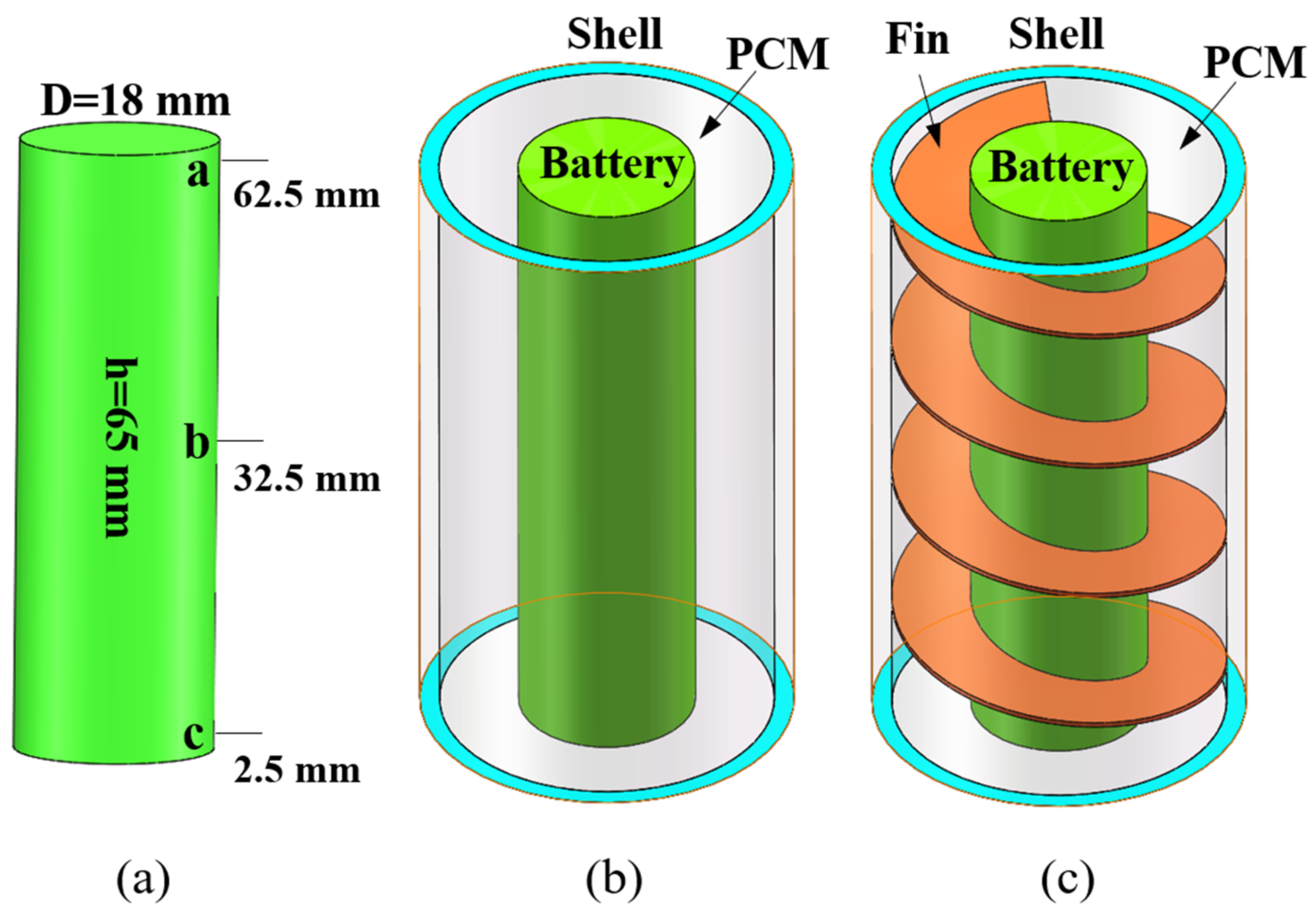
This study involves three physical models, namely single battery (Figure 1a), pure PCM + single battery (Figure 1b), and PCM + fin + battery (Figure 1c), which mainly consists of 18650-type cylindrical battery, aluminum alloy fin, PCM and acrylic shell. A cylindrical electric heater (18 mm in diameter, 65 mm in height) was used to simulate the battery. The thickness of the PCM was fixed as 8 mm, which was experimentally demonstrated to be the optimal heat dissipation condition according to the work by Sun et al. [47]. The cylindrical container shell for the single battery system has an inner diameter of 34 mm and a height of 65 mm. The battery is arranged in the middle of the container, the fin closely clings to the battery and the empty space is filled with PCM. In current study, commercial solid–solid PCM was used, the main component of which is paraffin wax. The 7075-aluminum alloy was used as the fin with a fixed thickness of 0.5 mm [38]. The typical parameters of the used battery cell, PCM, fin and acrylic container are specified in Table 2.
2.2. Assumptions and Governing Equations
In this study, the computational domain that needed to be simulated included the non-metallic shell, PCM, fins and the battery cell. An enthalpy-porosity-based approach was employed, in which the porous region was used to represent a solid fuzzy region with a liquid fraction equal to the porosity [48]. To simplify the numerical simulation, the following assumptions were considered [49,50,51]:
- The physical properties of various materials inside the battery are consistent and isotropic.
- Joule heat is the main source of heat produced by batteries, ignoring the effect of reversible entropy heat generation.
- The thermal conductivity and specific heat capacity of the single battery and various performance parameters of the battery will not change due to changes in battery temperature and residual state of charge (SOC).
- The heat generation inside the battery is uniform.
- The solid and liquid phases of the PCM are homogeneous and isotropic.
- The density of the PCM is approximately determined by Boussinesq, and other thermophysical properties are constant and uniform. The Boussinesq model will take into account buoyancy during natural convection.
- The gravitational acceleration is constant 9.81 m/s2 in the negative Z-axis direction.
- Based on these assumptions, the governing equations are as follows:
- The energy equation for the battery can be expressed as [52]
The energy equation for the fins and shell is
where is density, T is temperature, t is time, is specific heat and is thermal conductivity.
To accurately simulate the melting of PCM, this work uses the enthalpy-porosity method, where the liquid fraction represents the proportion of PCM undergoing phase change. In each cycle, the PCM domain, the mushy region, i.e., the space between the solid and the liquid, is determined according to the enthalpy balance, and this part is classified as the porous region. In the simulation, the thermophysical properties of the PCM, such as thermal conductivity, viscosity and specific heat, were treated as constants. When a sufficient amount of PCM melts into the liquid, natural convection may dominate during heat transfer. In the momentum equation, the effects of natural convection are approximated using Boussinesq [53].
The heat transfer inside the PCM is divided into specific heat and latent heat, which are controlled by the following formulas [54].
The energy equation for PCM is
The expression for the enthalpy of PCM is
The expression for the melting of PCM within a certain range is
where and H are the latent heat content and enthalpy, respectively, h is sensible heat, is coefficient of thermal expansion and is specific latent heat.
2.3. Boundary Conditions and Calculation Steps
The initial temperature of the system was 298.15 K. According to the heat production results of Ref. [55], the heat production rates of 10,447.00 W/m3, 41,788.37 W/m3 and 94023.84 W/m3 were determined at the current rates of 1 C, 2 C and 3 C. The natural convection between the shell and air was set as constant with a heat transfer coefficient of 5.7 W/m2K [55]. The bottom of the system was insulated, and the top and sides were subject to natural convection [43].
The 3D numerical simulation in this work was achieved using the commercial CFD software ANSYS 2021R1 Fluent. Before that step, SolidWorks software was used to build the physical models, and CFD ICEM software was used to generate meshes. Finite volume-based numerical simulations were developed to solve the governing Equations (1)–(7). The pressure-based solver was used to solve the continuity and momentum equations in the phase transition process. The change of PCM density was almost negligible. The solving procedure used the default solidification and melting model, SIMPLEC algorithm for pressure–velocity coupling, and pressure correction equation PRESTO!. In addition, the discrete energy and momentum equations used second-order upwind, and the under-relaxation factor remained the default.
2.4. Grid Independence Test
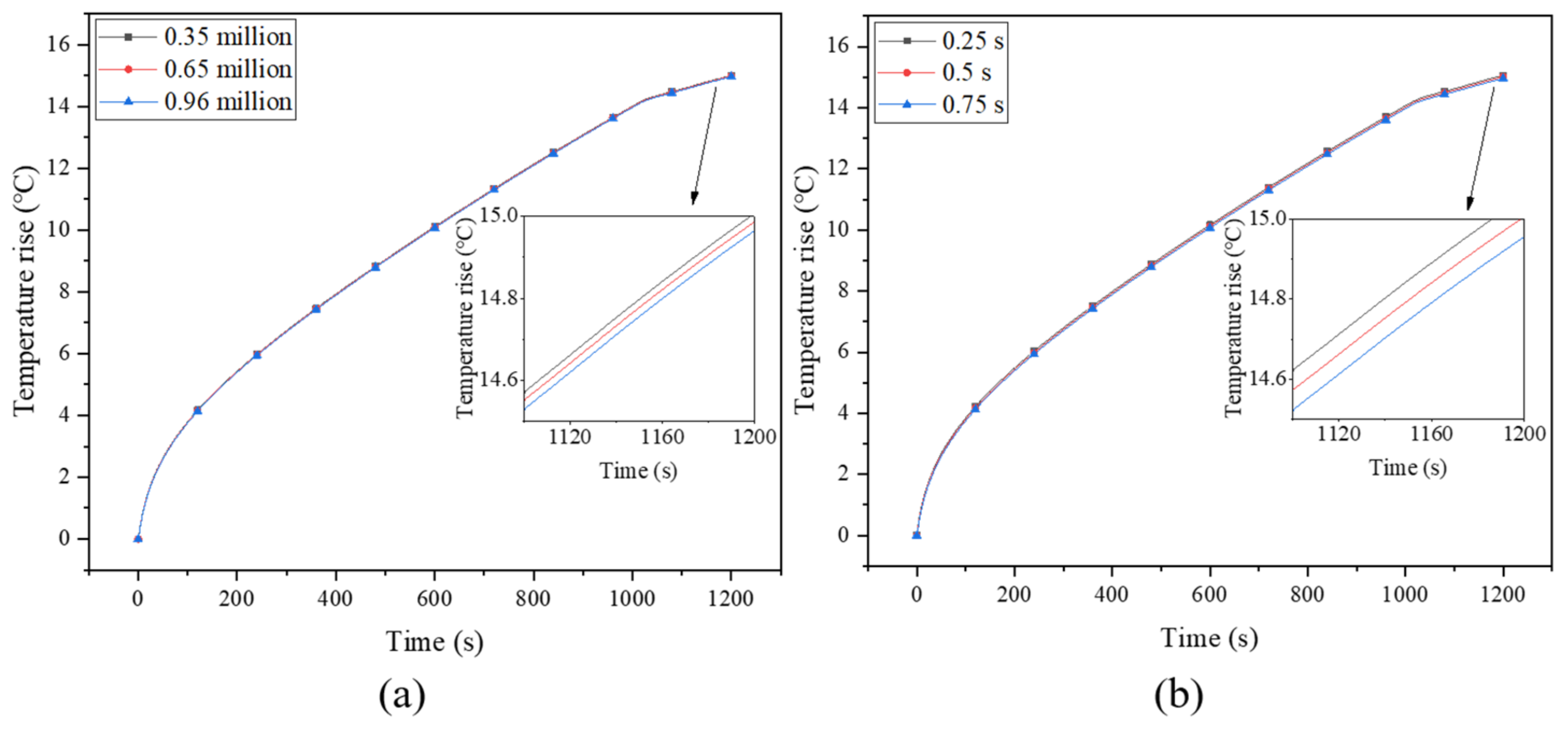
The size of the grid and the time step are the two main factors that affect the error of the result. Therefore, in order to ensure the accuracy of the numerical results and calculate the optimal time step and grid size, a grid independence test was conducted for the model with 0.5-mm-thick and 4-turn fins, and the grid numbers of 350,000, 650,000 and 960,000 were tested, as shown in Figure 2a. The result was the temperature of point b on the battery surface at a discharge rate of 3 C. When the number of grids decreases from 960,000 to 350,000, the maximum difference in battery surface temperature is only 0.27%, which means that the number of grids of 350,000 meets the calculated requirements. Since the melting of PCM is a time-varying process, a small time step is usually required to obtain accurate results [38]. The test results for time steps of 0.25 s, 0.5 s and 0.75 s are shown in Figure 2b, where slight differences among them can be observed. Since 0.25 s would result in a very long calculation time, the time step of 0.5 s was used in current study.
2.5. Model Validation
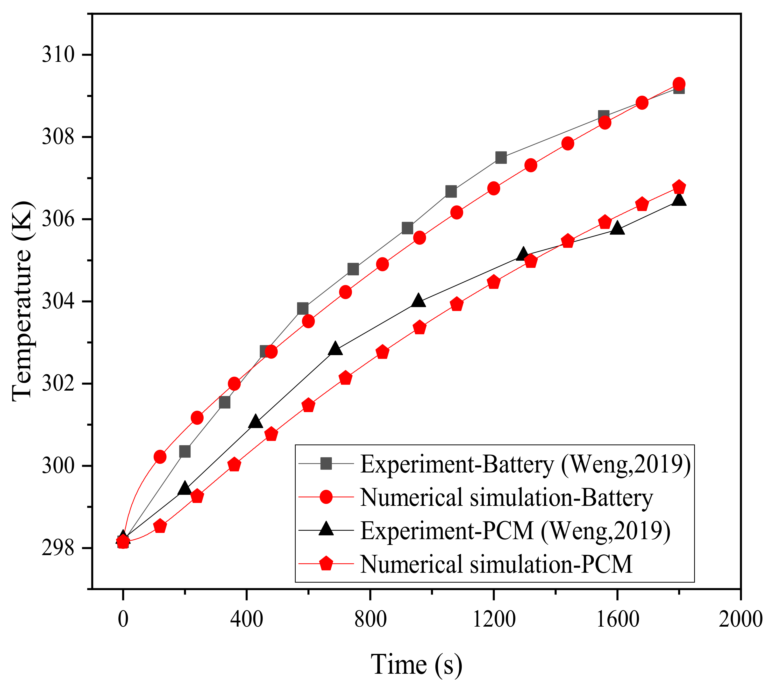
In order to compare and verify with the experimental results of Weng et al. [43], this paper was developed according to the following experimental conditions. In the experiment, the battery model was an 18,650 cylindrical LIB, and there were four circular fins with widths of 8 mm and thicknesses of 0.5 mm. The thickness of the PCM was the same as the width of the fins, and the thickness of the shell was 2 mm. The temperature rise process of the battery (point b) under the 2 C discharge rate was measured experimentally, and the physical model simulated in this paper was designed according to these working conditions, and then compared with the experimental results in the literature. The verification results for the temperatures of the battery and PCM are plotted in Figure 3. The results show that the simulated data is basically consistent with the experiment, and the maximum temperature difference between them is 0.86 °C. The error rate, expressed as ( and ) denoting the temperature data obtained by the experiment and simulation, respectively, does not exceed 0.28%. This verifies that the model in this work can simulate the thermal characteristics of lithium batteries and can therefore be further used.
3. Results
3.1. The Effectiveness of Pure PCM
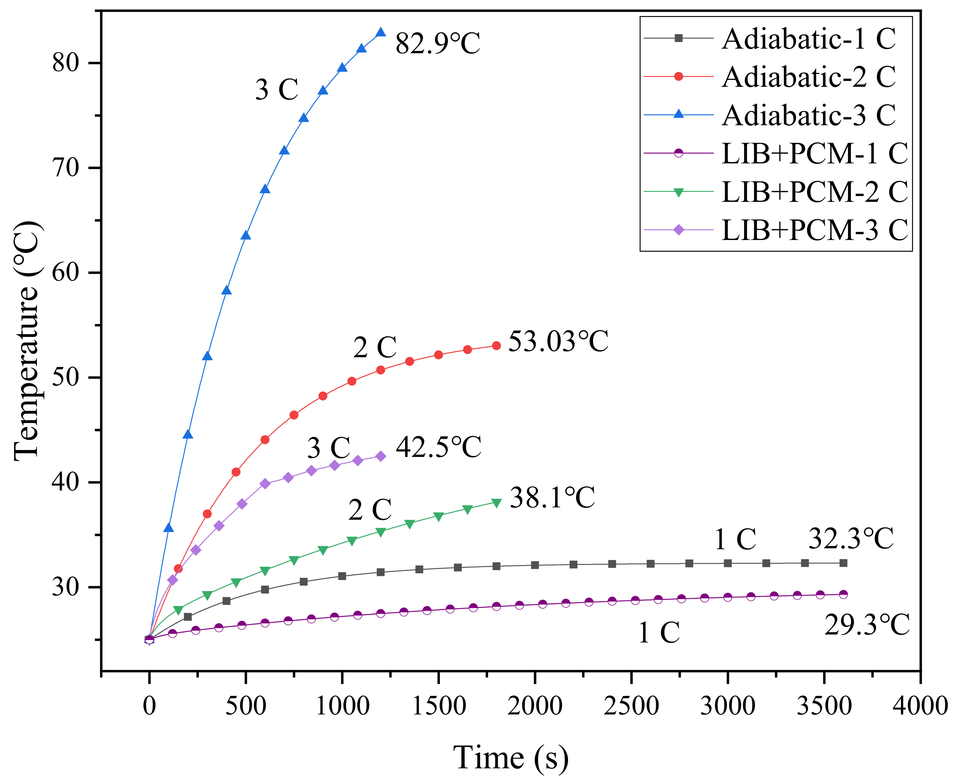
The role of PCM in the battery cooling system was investigated through a comparison with the adiabatic conditions, as shown in Figure 4, which displays the simulated results based on the single-battery cooling system in Figure 1a. Under adiabatic conditions, for a 1 C discharge rate, the maximum temperature of the battery surface is only 32.3 °C, much lower than 40 °C, while those for 2 C and 3 C discharge rates are 53.03 °C and 82.9 °C, respectively, far exceeding the safe operating temperature range. Thus, an effective BTMS is required to cool the battery. The battery temperatures under different discharge rates are simulated for cases with pure PCM as the cooling medium. It can be observed that the PCM can alleviate the temperature rise of the battery. At a 2 C discharge rate, the battery temperature is reduced by 53.3% ((53.03–38.1)/53.03 = 53.3%), while that at 3 C is about 48.7% ((82.9–42.5)/82.9 = 48.7%), and the maximum temperature still exceeds 40 °C. In practical use, the charge–discharge rate may be higher than 3 C, and the heat generated at higher charging rates may not be absorbed efficiently due to the limited energy storage capacity and low thermal conductivity of PCM [20]. If the heat accumulated at a high charge–discharge rate cannot be dissipated effectively, it will cause the failure of the BTMS. From this point of view, pure PCM is obviously not enough to meet the requirements of effective heat dissipation. In this case, the metal heat sinks can greatly extend the thermal boundary, allowing the heat source to penetrate the PCM, thereby enhancing the heat transfer efficiency of the system.
3.2. Comparison of Circular and Spiral Fins
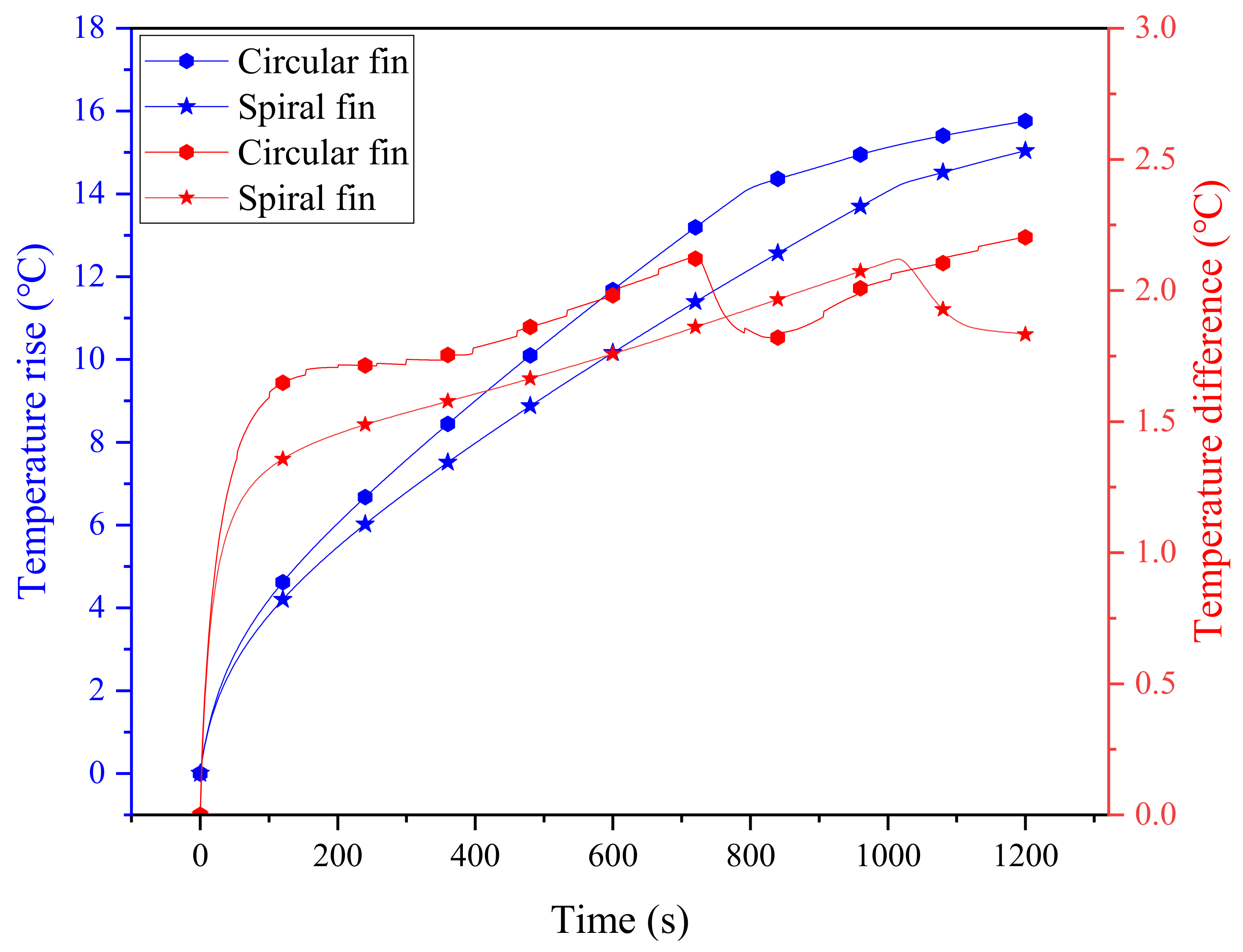
Here, the cooling system with four circular fins (0.5 mm thickness) is selected as a baseline for comparison. In order to guarantee the reliability of the comparison results, the contact length between the spiral fin and the battery is maintained to be consistent with the circular fin case, i.e., the spiral length, calculated as ( is the diameter of the battery; is the pitch of the spiral), is equivalent to four rings (about 226.08 mm), which is about 3.88 turns for the spiral fin. At a 3 C discharge rate, the maximum temperatures of the battery for the two comparative cases are shown in Figure 5, where the improvement effect of the spiral fin can be clearly observed. Specifically, the maximum temperature rise and temperature difference of the battery cooling system with circular fins are 15.76 °C and 2.2 °C, respectively, and these values for spiral fins are 15.04 °C and 1.83 °C. During the discharging process, the maximum temperature difference between the two cases even approaches about 1.95 °C in the range of 700∼800 s. This implies that the spiral fin can alleviate the rapid temperature rise and temperature inhomogeneity of the battery, ensuring its durability and thermal safety. This may be due to the special advantages of the spiral fin with its evenly distributed structure, which can efficiently match with PCM to present better cooling performance. It can also be noted that the temperature differences for the two fins exhibit a sharp decrease in the later stage, which is mainly due to the fact that the rise of the maximum temperature of the battery slows down, and thus, the temperature difference correspondingly decreases. In contrast, however, the temperature difference of circular fins is not as smooth as that of spiral fins, which further proves its instability.
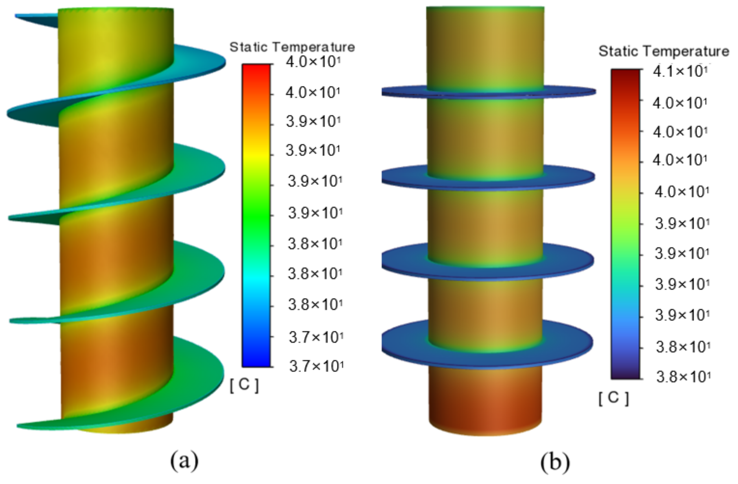
According to the temperature cloud diagram in Figure 6, the battery temperature exhibits a gradually increasing trend from top to bottom, which is attributed to the presupposed boundary conditions of the natural convection at the top of the battery and the insulation at the bottom. The results also show that the maximum temperature for the circular fins still exceeds 40 °C, and, especially, that the heat dissipation capacity of the circular fins at the bottom of the battery is rather limited. As it is constrained by the shape of the circular fins, even if the heat of the battery can be dissipated through the fin, it is still concentrated in the vicinity of the fin, and the area away from it cannot be sufficiently balanced. In contrast, the cooling system with the spiral fin shows better uniformity due to its evenly distributed structure, which effectually addresses the issue of local heat accumulation to a certain extent, making the temperature distribution of the entire battery more uniform. Furthermore, the maximum battery temperature for the spiral fins can be maintained at no higher than 40 °C, effectively improving the cooling performance of the system.
3.3. Influence of the Width of the Spiral Fin
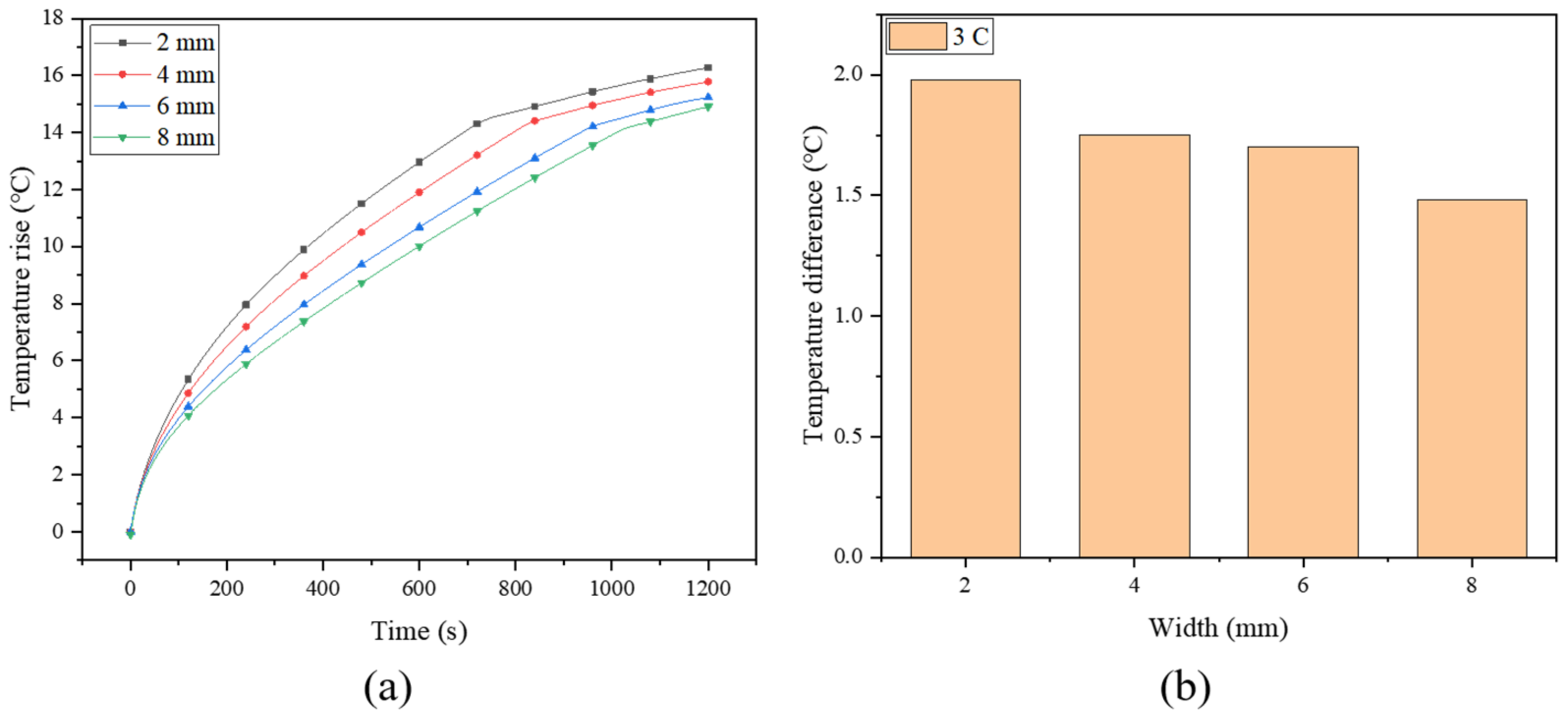
As mentioned previously, the fins create new heat conduction channels within the PCM, enhancing the heat transfer process, while the spiral fin makes the heat conduction network more uniform. In order to determine the optimal dimension of the spiral fin, four spiral turns are maintained constant to investigate the effect of the width of the spiral fin. The histories of the maximum temperature of the battery (at a discharge rate of 3 C) under different fin widths (2, 4, 6 and 8 mm) are simulated and plotted in Figure 7a. Previous work has demonstrated that the battery temperature decreases with increasing fin width, while the temperature uniformity of the battery increases with the increase of fin width [16]. Due to the high thermal conductivity of the fin, the heat of the battery can be transferred efficiently from the core area of the battery to the outer boundary of the battery module through the fin, and the surrounding PCM cools the battery by absorbing the heat transferred by the fin. This indicates that increasing the width of the fin can effectively improve the thermal management performance of the system [53]. Compared with the pure PCM system, the maximum temperatures for the four fin widths can be reduced by about 4.0%, 8.3%, 11.9% and 14.2%, respectively. For a narrower spiral fin, the PCM cannot properly absorb the heat of the battery. In order to effectively utilize the PCM at the periphery of the module in terms of latent heat storage, a wider fin is more suitable for this system. Similar work has also been conducted by Zheng et al. [38], who numerically investigated the influence of three rectangular fin widths (2.5, 5.0 and 7.5 mm) on battery temperature, and found that the battery temperature decreased by 6.09%, 9.52% and 11.74%, respectively, under the three widths compared with the case without fins. By contrast, the spiral fin in the current study exhibits a better cooling improvement effect.
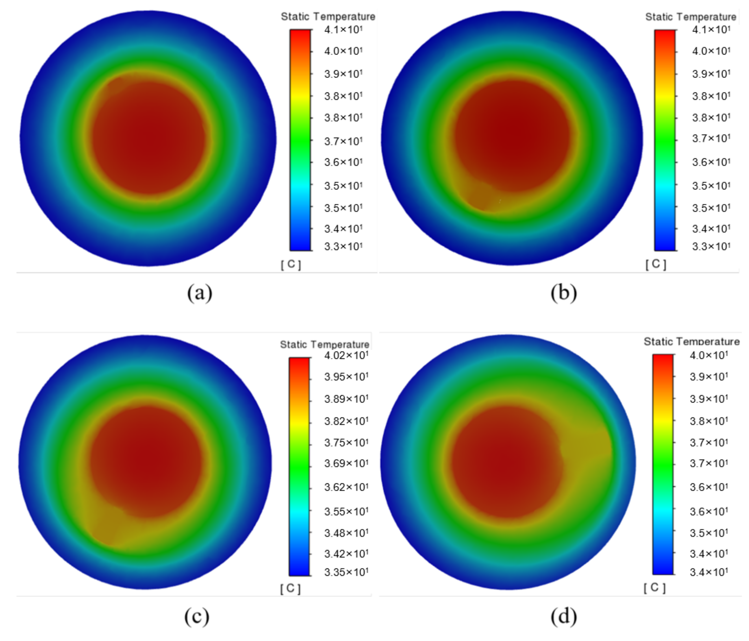
Figure 7b shows the temperature difference of the battery under different widths. It shows that the temperature difference of the battery decreases from 1.98 °C to 1.48 °C with the fin width ranging from 2∼8 mm, indicating that increasing the fin width can improve the temperature uniformity of the battery. The temperature nephogram in Figure 8 shows that the temperature gradually decreases in the radial direction. Due to the poor thermal conductivity of the PCM, the area without a fin exhibits an apparent temperature gradient, while that with a fin can better transfer heat to the surrounding PCM. Moreover, the wider fin allows for a larger contact area between the fin and the PCM, for which the PCM can be more fully utilized, especially the peripheral PCM in the system. Therefore, by continuously optimizing the fin, the heat generated in the battery can be transferred to a place farther away from the battery, and quickly absorbed by the PCM.
3.4. Influence of the Number of Spiral Turns
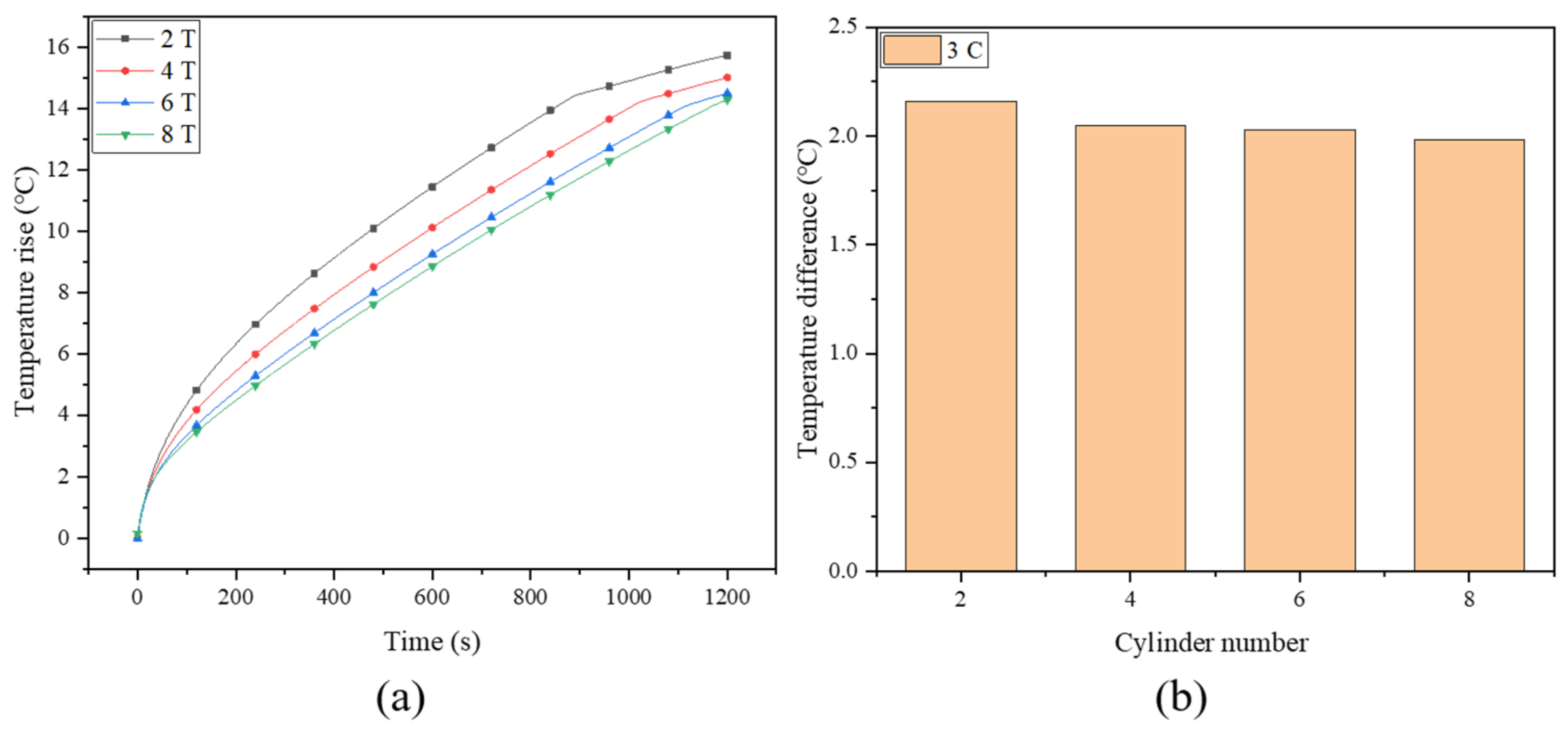
To further enhance the performance of the system, the effect of the number of fin turns was also investigated. Figure 9a depicts the maximum temperature rise of the battery for the spiral fins with the number of turns being two (2 T), four (4 T), six (6 T) and eight (8 T), where the fin width and battery discharge rate are fixed at 8 mm and 3 C, respectively. With the increase in the number of turns, the maximum battery temperature decreases from 40.88 °C to 39.28 °C, which can be maintained in a safe operating temperature range. When the number of fin turns increases from 2 T to 6 T, the maximum battery temperature drops significantly, while the difference between 6 T and 8 T is rather small, with an insignificant improvement of about 0.22 °C (from 39.5 °C to 39.28 °C). In effect, although the thermal conductivity of the system is improved by increasing the number of turns, it should be noted that in the limited battery cooling system, a continuous increase in the number of fins will occupy too much space, accordingly resulting in a decrease in the amount of PCM. This will attenuate the energy storage capacity of the PCM; thus, the excessive fins may not always play a positive role in enhancing cooling effectiveness [56]. Therefore, the number of fin turns should be optimized to obtain the maximum heat storage capacity and heat dissipation capability at the same time. The temperature differences under different fin turns are depicted in Figure 9b, where the temperature uniformity of the battery is also improved with the increasing fin turns, but to a very limited extent.
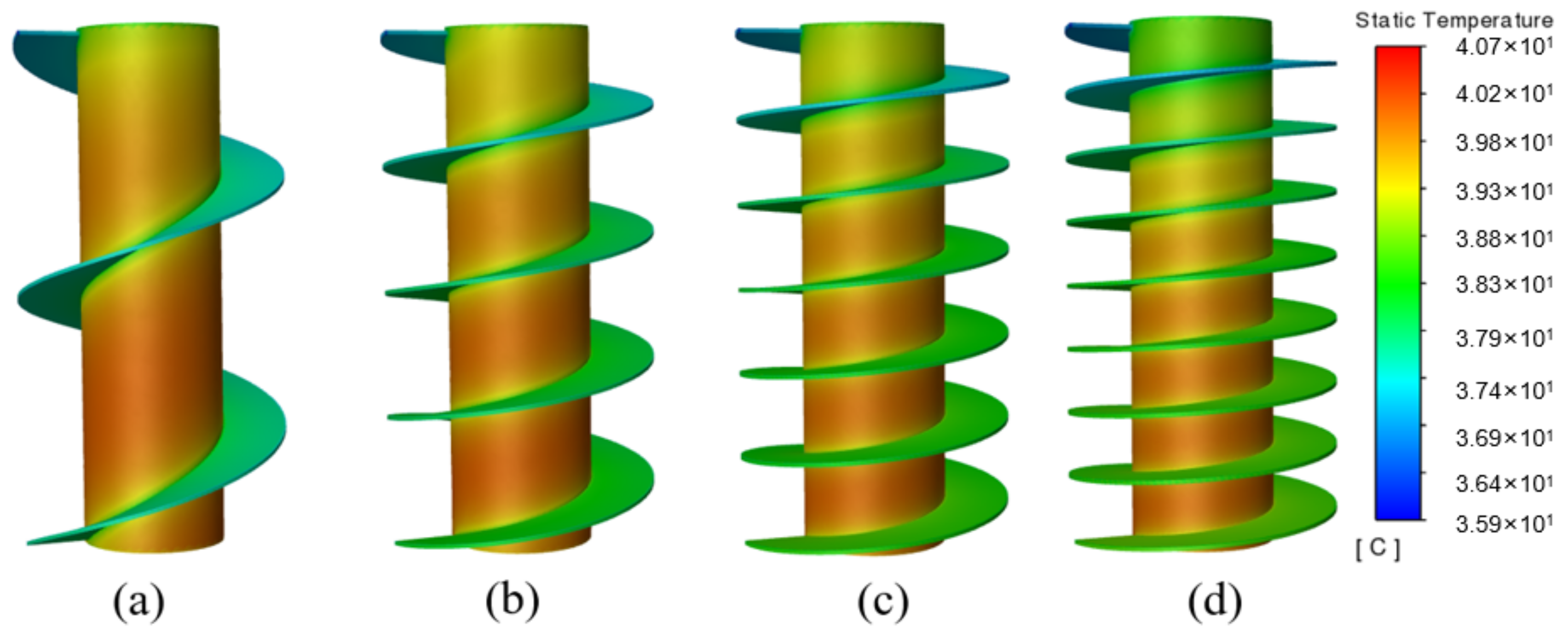
The temperature cloud diagrams under different fin turns are depicted in Figure 10, where the entire heat conduction network is extended, i.e., the effective heat transfer area is increased with the increasing number of fin turns. Therefore, the battery temperature is better controlled, and the temperature of the bottom is more uniform. On the whole, the spiral fin with 6 T may be the optimal choice in the current study.
3.5. Influence of Ambient Temperature
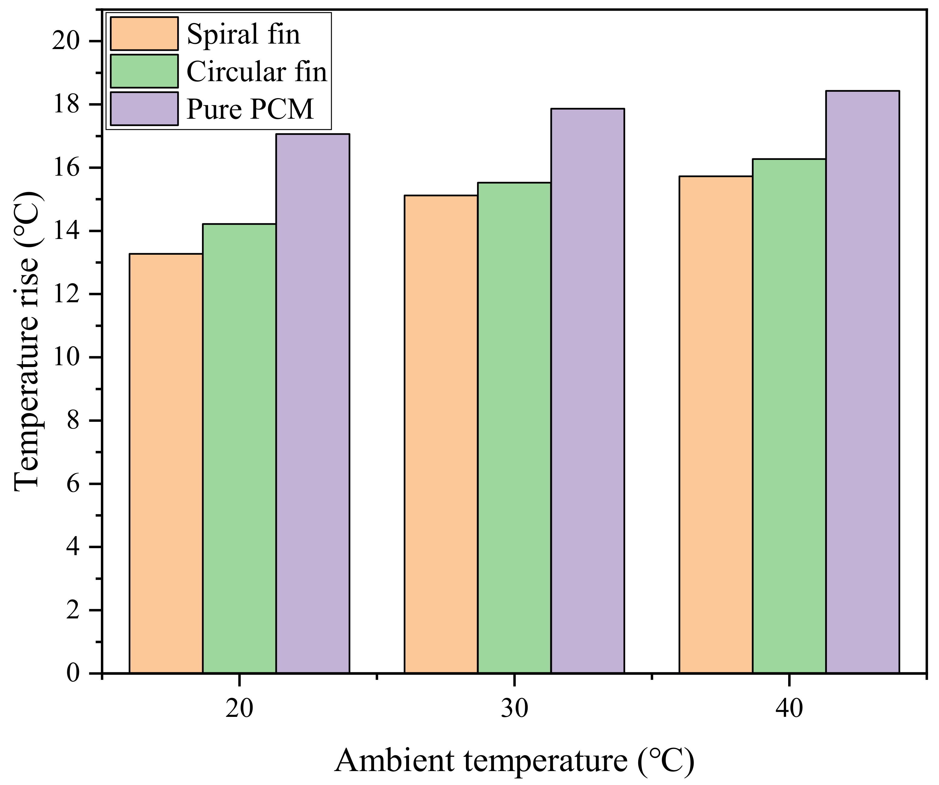
The power battery can be used in different seasons, which requires the BTMS to stably exert its heat dissipation performance under different ambient temperatures. Therefore, it is necessary to analyze the impact of ambient temperature on the cooling performance of the system. The previous work in this paper was based on the simulation of the ambient temperature of 25 °C, so the heat dissipation of the system was also studied when the ambient temperature was 20 °C, 30 °C and 40 °C. Figure 11 shows the comparison of the maximum temperature rise of the battery in pure PCM, PCM-spiral and PCM-circular systems at different ambient temperatures. The maximum temperature rise of the system increases with the increase in the ambient temperature. For the PCM-based BTMS, the PCM will absorb more heat from the higher ambient temperature, thereby reducing the energy storage capacity [39]. When the ambient temperature rises from 20 °C to 40 °C, the maximum temperature rise of the battery under the pure PCM system rises from 17.05 °C to 18.43 °C, while those of the PCM-spiral and PCM-circular systems range from 13.27∼15.72 °C and 14.22∼16.27 °C, respectively. Compared with the pure PCM system, the maximum temperature rise of the PCM-spiral optimized system decreases by 3.78 °C, 2.74 °C and 2.71 °C, respectively. Compared with the PCM-circular system, it decreases by 0.95 °C, 0.41 °C and 0.55 °C, respectively. In summary, the PCM-plus-spiral-fin system still has significant advantages in high-temperature environments.
4. Conclusions
In this paper, a numerical study of a battery cooling system with a combination of PCM and a novel spiral fin was conducted. The optimal fin width and fin turn number were simulated and analyzed, and the effect of ambient temperature on the cooling effectiveness of the system was also investigated. The major findings are summarized as follows:
- 1.
- Compared with circular fins, a spiral fin of the same line length can reduce the maximum temperature of the battery by 0.72 °C. The most important point is that the spiral fin showed a greater advantage in improving the temperature uniformity of the battery, which made the temperature difference decrease by 16.8%.
- 2.
- Compared with the finless system, when the width of the spiral fin was 2, 4, 6 and 8 mm, the maximum temperature of the battery decreased by 4%, 8.3%, 11.9% and 14.2%, respectively.
- 3.
- When the number of turns of the fin increased from 2 T to 8 T, the maximum temperature of the battery decreased from 40.88 °C to 39.28 °C. Moreover, when the number of turns increased from 6 T to 8 T, the temperature drop was no longer obvious, being only 0.22 °C.
- 4.
- When the ambient temperature was 20 °C, 30 °C and 40 °C, the maximum temperature rise of the PCM-spiral optimization system decreased by 3.78 °C, 2.74 °C and 2.71 °C, respectively, compared with the pure PCM system, and by 0.95 °C, 0.41 °C and 0.55 °C, respectively, compared with the PCM-circular system. This shows that the PCM-spiral fin system has certain advantages even in a high-temperature environment.
Author Contributions
Conceptualization, J.L. and X.L.; methodology, J.L. and X.L.; software, Q.M.; validation, Q.M.; formal analysis, Q.M.; investigation, Q.M. and J.L.; resources, J.L.; data curation, Q.M.; writing—original draft preparation, Q.M.; writing—review and editing, J.L. and X.L.; visualization, Q.M.; supervision, J.L.; project administration, J.L.; funding acquisition, J.L. All authors have read and agreed to the published version of the manuscript.
Funding
This research was funded by the National Natural Science Foundation of China, grant number 51909152.
Data Availability Statement
Data available on request due to restrictions, e.g., privacy or ethical restrictions.
Acknowledgments
This research is financially supported by the National Natural Science Foundation of China (No. 51909152). The authors deeply appreciate the support.
Conflicts of Interest
The authors declare no conflict of interest.
References
- Shahbaz, M.; Raghutla, C.; Chittedi, K.R.; Jiao, Z.; Vo, X.V. The Effect of Renewable Energy Consumption on Economic Growth: Evidence from the Renewable Energy Country Attractive Index. Energy 2020, 207, 118162. [Google Scholar] [CrossRef]
- Xu, F.; Zhai, Y.; Zhang, E.; Liu, Q.; Jiang, G.; Xu, X.; Qiu, Y.; Liu, X.; Wang, H.; Kaskel, S. Ultrastable Surface-Dominated Pseudocapacitive Potassium Storage Enabled by Edge-Enriched N-Doped Porous Carbon Nanosheets. Angew. Chem. Int. Ed. Engl. 2020, 59, 19460–19467. [Google Scholar] [CrossRef] [PubMed]
- Tran, M.-K.; Akinsanya, M.; Panchal, S.; Fraser, R.; Fowler, M. Design of a Hybrid Electric Vehicle Powertrain for Performance Optimization Considering Various Powertrain Components and Configurations. Vehicles 2020, 3, 20–32. [Google Scholar] [CrossRef]
- Saw, L.H.; Poon, H.M.; Thiam, H.S.; Cai, Z.; Chong, W.T.; Pambudi, N.A.; King, Y.J. Novel Thermal Management System Using Mist Cooling for Lithium-Ion Battery Packs. Appl. Energy 2018, 223, 146–158. [Google Scholar] [CrossRef] [Green Version]
- Lander, L.; Kallitsis, E.; Hales, A.; Edge, J.S.; Korre, A.; Offer, G. Cost and Carbon Footprint Reduction of Electric Vehicle Lithium-Ion Batteries through Efficient Thermal Management. Appl. Energy 2021, 289, 116737. [Google Scholar] [CrossRef]
- Farag, M.; Sweity, H.; Fleckenstein, M.; Habibi, S. Combined Electrochemical, Heat Generation, and Thermal Model for Large Prismatic Lithium-Ion Batteries in Real-Time Applications. J. Power Sources 2017, 360, 618–633. [Google Scholar] [CrossRef]
- Weng, J.; Ouyang, D.; Yang, X.; Chen, M.; Zhang, G.; Wang, J. Alleviation of Thermal Runaway Propagation in Thermal Management Modules Using Aerogel Felt Coupled with Flame-Retarded Phase Change Material. Energy Convers. Manag. 2019, 200, 112071. [Google Scholar] [CrossRef]
- Wu, W.; Wu, W.; Wang, S. Form-Stable and Thermally Induced Flexible Composite Phase Change Material for Thermal Energy Storage and Thermal Management Applications. Appl. Energy 2019, 236, 10–21. [Google Scholar] [CrossRef]
- Malik, M.; Dincer, I.; Rosen, M.A. Review on Use of Phase Change Materials in Battery Thermal Management for Electric and Hybrid Electric Vehicles: Review on Use of PCM in Battery Thermal Management for EV and HEV. Int. J. Energy Res. 2016, 40, 1011–1031. [Google Scholar] [CrossRef]
- Zheng, Y.; Shi, Y.; Huang, Y. Optimisation with Adiabatic Interlayers for Liquid-Dominated Cooling System on Fast Charging Battery Packs. Appl. Therm. Eng. 2019, 147, 636–646. [Google Scholar] [CrossRef]
- Feng, X.; Xu, C.; He, X.; Wang, L.; Zhang, G.; Ouyang, M. Mechanisms for the Evolution of Cell Variations within a LiNixCoyMnzO2/Graphite Lithium-Ion Battery Pack Caused by Temperature Non-Uniformity. J. Clean. Prod. 2018, 205, 447–462. [Google Scholar] [CrossRef]
- Chen, K.; Chen, Y.; She, Y.; Song, M.; Wang, S.; Chen, L. Construction of Effective Symmetrical Air-Cooled System for Battery Thermal Management. Appl. Therm. Eng. 2020, 166, 114679. [Google Scholar] [CrossRef]
- Akinlabi, A.A.H.; Solyali, D. Configuration, Design, and Optimization of Air-Cooled Battery Thermal Management System for Electric Vehicles: A Review. Renew. Sustain. Energy Rev. 2020, 125, 109815. [Google Scholar] [CrossRef]
- Zhang, L.; Chen, Q.; Wang, T. Effects of Air-Cooling Structure on Cooling Performance Enhancement of Prismatic Lithium-ion Battery Packs Based on Coupled Electrochemical-thermal Model. Energy Sci. Eng. 2021, 9, 1450–1464. [Google Scholar] [CrossRef]
- Sundin, D.W.; Sponholtz, S. Thermal Management of Li-Ion Batteries with Single-Phase Liquid Immersion Cooling. IEEE Open J. Veh. Technol. 2020, 1, 82–92. [Google Scholar] [CrossRef]
- Liu, F.; Wang, J.; Liu, Y.; Wang, F.; Yang, N.; Liu, X.; Liu, H.; Li, W.; Liu, H.; Huang, B. Performance Analysis of Phase Change Material in Battery Thermal Management with Biomimetic Honeycomb Fin. Appl. Therm. Eng. 2021, 196, 117296. [Google Scholar] [CrossRef]
- Huang, R.; Li, Z.; Hong, W.; Wu, Q.; Yu, X. Experimental and Numerical Study of PCM Thermophysical Parameters on Lithium-Ion Battery Thermal Management. Energy Rep. 2020, 6, 8–19. [Google Scholar] [CrossRef]
- Qin, P.; Liao, M.; Zhang, D.; Liu, Y.; Sun, J.; Wang, Q. Experimental and Numerical Study on a Novel Hybrid Battery Thermal Management System Integrated Forced-Air Convection and Phase Change Material. Energy Convers. Manag. 2019, 195, 1371–1381. [Google Scholar] [CrossRef]
- Jaguemont, J.; Omar, N.; Van den Bossche, P.; Mierlo, J. Phase-Change Materials (PCM) for Automotive Applications: A Review. Appl. Therm. Eng. 2018, 132, 308–320. [Google Scholar] [CrossRef]
- Weng, J.; Ouyang, D.; Yang, X.; Chen, M.; Zhang, G.; Wang, J. Optimization of the Internal Fin in a Phase-Change-Material Module for Battery Thermal Management. Appl. Therm. Eng. 2020, 167, 114698. [Google Scholar] [CrossRef]
- Zhang, J.; Shao, D.; Jiang, L. Advanced thermal management system driven by phase change materials for power lithium-ion batteries: A review. Renew. Sustain. Energy Rev. 2022, 159, 112207. [Google Scholar] [CrossRef]
- Hallaj, S.A.; Selman, J.R. A Novel Thermal Management System for Electric Vehicle Batteries Using Phase-Change Material. J. Electrochem. Soc. 2000, 147, 3231. [Google Scholar] [CrossRef]
- Verma, A.; Shashidhara, S.; Rakshit, D. A Comparative Study on Battery Thermal Management Using Phase Change Material (PCM). Therm. Sci. Eng. Prog. 2019, 11, 74–83. [Google Scholar] [CrossRef]
- Liu, J.; Fan, Y.; Xie, Q. Temperature Mitigation Effect of Phase Change Material on Overcharging Lithium-Ion Batteries: An Experimental Study. J. Therm. Anal. Calorim. 2022, 147, 5153–5163. [Google Scholar] [CrossRef]
- Wang, Y.; Wang, Z.; Min, H.; Li, H.; Li, Q. Performance Investigation of a Passive Battery Thermal Management System Applied with Phase Change Material. J. Energy Storage 2021, 35, 102279. [Google Scholar] [CrossRef]
- Liu, J.; Fan, Y.; Xie, Q. An Experimental Study on the Thermal Performance of Mixed Phase Change Materials-Based Battery Cooling System. J. Energy Storage 2022, 46, 103839. [Google Scholar] [CrossRef]
- Heyhat, M.M.; Mousavi, S.; Siavashi, M. Battery Thermal Management with Thermal Energy Storage Composites of PCM, Metal Foam, Fin and Nanoparticle. J. Energy Storage 2020, 28, 101235. [Google Scholar] [CrossRef]
- Lazrak, A.; Fourmigué, J.-F.; Robin, J.-F. An Innovative Practical Battery Thermal Management System Based on Phase Change Materials: Numerical and Experimental Investigations. Appl. Therm. Eng. 2018, 128, 20–32. [Google Scholar] [CrossRef]
- Siddique, A.R.M.; Mahmud, S.; Heyst, B.V. A Comprehensive Review on a Passive (Phase Change Materials) and an Active (Thermoelectric Cooler) Battery Thermal Management System and Their Limitations. J. Power Sources 2018, 401, 224–237. [Google Scholar] [CrossRef]
- Jiang, G.; Huang, J.; Fu, Y.; Cao, M.; Liu, M. Thermal Optimization of Composite Phase Change Material/Expanded Graphite for Li-Ion Battery Thermal Management. Appl. Therm. Eng. 2016, 108, 1119–1125. [Google Scholar] [CrossRef]
- Zou, D.; Ma, X.; Liu, X.; Zheng, P.; Hu, Y. Thermal Performance Enhancement of Composite Phase Change Materials (PCM) Using Graphene and Carbon Nanotubes as Additives for the Potential Application in Lithium-Ion Power Battery. Int. J. Heat Mass Transf. 2018, 120, 33–41. [Google Scholar] [CrossRef]
- Alipanah, M.; Li, X. Numerical Studies of Lithium-Ion Battery Thermal Management Systems Using Phase Change Materials and Metal Foams. Int. J. Heat Mass Transf. 2016, 102, 1159–1168. [Google Scholar] [CrossRef]
- Buonomo, B.; Ercole, D.; Manca, O.; Menale, F. Thermal Cooling Behaviors of Lithium-Ion Batteries by Metal Foam with Phase Change Materials. Energy Procedia 2018, 148, 1175–1182. [Google Scholar] [CrossRef]
- Zhi, M.; Fan, R.; Yang, X.; Zheng, L.; Yue, S.; Liu, Q.; He, Y. Recent Research Progress on Phase Change Materials for Thermal Management of Lithium-Ion Batteries. J. Energy Storage 2022, 45, 103694. [Google Scholar] [CrossRef]
- Usman, H.; Ali, H.M.; Arshad, A.; Ashraf, M.J.; Khushnood, S.; Janjua, M.M.; Kazi, S.N. An Experimental Study of PCM Based Finned and Un-Finned Heat Sinks for Passive Cooling of Electronics. Heat Mass Transf. 2018, 54, 3587–3598. [Google Scholar] [CrossRef]
- Ali, H.M.; Arshad, A. Experimental Investigation of N-Eicosane Based Circular Pin-Fin Heat Sinks for Passive Cooling of Electronic Devices. Int. J. Heat Mass Transf. 2017, 112, 649–661. [Google Scholar] [CrossRef]
- Wang, Z.; Zhang, H.; Xia, X. Experimental Investigation on the Thermal Behavior of Cylindrical Battery with Composite Paraffin and Fin Structure. Int. J. Heat Mass Transf. 2017, 109, 958–970. [Google Scholar] [CrossRef]
- Zheng, N.; Fan, R.; Sun, Z.; Zhou, T. Thermal Management Performance of a Fin-enhanced Phase Change Material System for the Lithium-ion Battery. Int. J. Energy Res. 2020, 44, 7617–7629. [Google Scholar] [CrossRef]
- Fan, R.; Zheng, N.; Sun, Z. Evaluation of Fin Intensified Phase Change Material Systems for Thermal Management of Li-Ion Battery Modules. Int. J. Heat Mass Transf. 2021, 166, 120753. [Google Scholar] [CrossRef]
- Liu, S.; Peng, H.; Hu, Z.; Ling, X.; Huang, J. Solidification Performance of a Latent Heat Storage Unit with Innovative Longitudinal Triangular Fins. Int. J. Heat Mass Transf. 2019, 138, 667–676. [Google Scholar] [CrossRef]
- Skaalum, J.; Groulx, D. Heat Transfer Comparison between Branching and Non-Branching Fins in a Latent Heat Energy Storage System. Int. J. Therm. Sci. 2020, 152, 106331. [Google Scholar] [CrossRef]
- Zhao, C.; Opolot, M.; Liu, M. Numerical study of melting performance enhancement for PCM in a circular enclosure with internal-external fins and metal foams. Int. J. Heat Mass Transf. 2020, 150, 119348. [Google Scholar] [CrossRef]
- Weng, J.; He, Y.; Ouyang, D.; Yang, X.; Zhang, G.; Wang, J. Thermal Performance of PCM and Branch-Structured Fins for Cylindrical Power Battery in a High-Temperature Environment. Energy Convers. Manag. 2019, 200, 112106. [Google Scholar] [CrossRef]
- Hasse, C.; Grenet, M.; Bontemps, A.; Dendievel, R.; Sallée, H. Realization, Test and Modelling of Honeycomb Wallboards Containing a Phase Change Material. Energy Build. 2011, 43, 232–238. [Google Scholar] [CrossRef] [Green Version]
- Yang, X.; Lu, Z.; Bai, Q. Thermal performance of a shell-and-tube latent heat thermal energy storage unit: Role of circular fins. Appl. Energy 2017, 202, 558–570. [Google Scholar] [CrossRef]
- Farouk, N.; Alotaibi, A.A.; Alshahri, A.H.; Almitani, K.H. Challenges in Incorporating Phase Change Materials into Thermal Control Units for Lithium-Ion Battery Cooling. J. Energy Storage 2022, 49, 104094. [Google Scholar] [CrossRef]
- Sun, Z.; Fan, R.; Yan, F.; Zhou, T.; Zheng, N. Thermal Management of the Lithium-Ion Battery by the Composite PCM-Fin Structures. Int. J. Heat Mass Transf. 2019, 145, 118739. [Google Scholar] [CrossRef]
- Al-abidi, A.A.; Bin Mat, S.; Sopian, K.; Sulaiman, M.Y.; Mohammed, A.T. CFD Applications for Latent Heat Thermal Energy Storage: A Review. Renew. Sustain. Energy Rev. 2013, 20, 353–363. [Google Scholar] [CrossRef]
- Seddegh, S.; Wang, X.; Henderson, A.D. Numerical Investigation of Heat Transfer Mechanism in a Vertical Shell and Tube Latent Heat Energy Storage System. Appl. Therm. Eng. 2015, 87, 698–706. [Google Scholar] [CrossRef]
- Zhang, F.; Yi, M.; Wang, P.; Liu, C. Optimization Design for Improving Thermal Performance of T-Type Air-Cooled Lithium-Ion Battery Pack. J. Energy Storage 2021, 44, 103464. [Google Scholar] [CrossRef]
- Kong, D.; Peng, R.; Ping, P.; Du, J.; Chen, G.; Wen, J. A Novel Battery Thermal Management System Coupling with PCM and Optimized Controllable Liquid Cooling for Different Ambient Temperatures. Energy Convers. Manag. 2020, 204, 112280. [Google Scholar] [CrossRef]
- Inc A. ANSYS FLUENT 18.0: Theory Guide; ANSYS: Cannonsburg, PA, USA, 2017.
- Mansir, I.B.; Sinaga, N.; Farouk, N.; Aljaghtham, M.; Diyoke, C.; Nguyen, D.D. Numerical Simulation of Dimensions and Arrangement of Triangular Fins Mounted on Cylindrical Lithium-Ion Batteries in Passive Thermal Management. J. Energy Storage 2022, 50, 104392. [Google Scholar] [CrossRef]
- Cao, J.; Ling, Z.; Fang, X.; Zhang, Z. Delayed Liquid Cooling Strategy with Phase Change Material to Achieve High Temperature Uniformity of Li-Ion Battery under High-Rate Discharge. J. Power Sources 2020, 450, 227673. [Google Scholar] [CrossRef]
- Choudhari, V.G.; Dhoble, A.S.; Panchal, S. Numerical Analysis of Different Fin Structures in Phase Change Material Module for Battery Thermal Management System and Its Optimization. Int. J. Heat Mass Transf. 2020, 163, 120434. [Google Scholar] [CrossRef]
- Ambekar, S.; Rath, P.; Bhattacharya, A. A Novel PCM and TCE Based Thermal Management of Battery Module. Therm. Sci. Eng. Prog. 2022, 29, 101196. [Google Scholar] [CrossRef]
Figure 1.
(a) Single battery; (b) pure PCM + single battery; (c) PCM + fin + single battery.

Figure 2.
(a) Grid independence test and (b) optimal time step.

Figure 3.
Model validation.

Figure 4.
Battery temperature in the case of adiabatic conditions and cooling with PCM.

Figure 5.
The evolution of temperature and temperature difference of two PCM-fin systems with circular and spiral fins.
Figure 5.
The evolution of temperature and temperature difference of two PCM-fin systems with circular and spiral fins.

Figure 6.
Temperature cloud diagrams of two kinds of PCM-fin systems: (a) spiral fins and (b) circular fins.
Figure 6.
Temperature cloud diagrams of two kinds of PCM-fin systems: (a) spiral fins and (b) circular fins.

Figure 7.
(a) The maximum temperature rise and (b) temperature difference of battery with different fin widths.
Figure 7.
(a) The maximum temperature rise and (b) temperature difference of battery with different fin widths.

Figure 8.
Temperature cloud diagram of cross section of battery with different fin widths: (a) 2 mm; (b) 4 mm; (c) 6 mm; (d) 8 mm.
Figure 8.
Temperature cloud diagram of cross section of battery with different fin widths: (a) 2 mm; (b) 4 mm; (c) 6 mm; (d) 8 mm.

Figure 9.
(a) Maximum battery temperature rise and (b) temperature difference of battery with different fin turns.
Figure 9.
(a) Maximum battery temperature rise and (b) temperature difference of battery with different fin turns.

Figure 10.
Temperature cloud diagram under different numbers of fin turns: (a) 2 T; (b) 4 T; (c) 6 T; (d) 8 T.
Figure 10.
Temperature cloud diagram under different numbers of fin turns: (a) 2 T; (b) 4 T; (c) 6 T; (d) 8 T.

Figure 11.
Maximum battery temperature rise for all three systems.


Table 1.
A review of research on various fin shapes.
| Refs. | Fin Shape | Major Findings |
|---|---|---|
| [37] | rectangular | Eight rectangular fins present the best cooling performance. |
| [38] | rectangular | When the heat production is 15 W, the working time with fins is 61% longer than that without fins. |
| [39] | rectangular | The length and direction of the fin have an effect on heat dissipation, and the heat is quickly transferred to the PCM through the embedded fin. |
| [40] | longitudinal triangular | The total solidification time of PCM is 38.3% shorter than that of rectangular finned structure. |
| [41] | branched | Branching fins impede the natural convection process of heat storage. |
| [42] | tree-like | In the case of foam metal, the melting rate of PCM is lower than that of fin. |
| [43] | X, I, V, Y-shaped | The X-shaped fin reduces the maximum temperature of the battery more effectively due to the large heat dissipation area. |
| [44] | honeycomb plate | The presence of the honeycomb structure reduces the temperature of the heat source. |
| [45] | circular | The insertion of circular fins into the PCM can reduce the melting time by 65%. |
| [46] | circular | The number of fins is increased from 3 to 5, and the temperature of the battery is reduced by 1–1.7 °C. |
Table 2.
Typical parameters of battery, PCM, fin and container [38].
Table 2.
Typical parameters of battery, PCM, fin and container [38].
| Parameter | Unit | Battery | PCM | Fin | Acrylic |
|---|---|---|---|---|---|
| Size/thickness | mm | 18 × 65 | - | 0.5 | 2 |
| Density | kg/m3 | 2720 | 820 | 2719 | 1215 |
| Heat capacity | J/(kg·K) | 300 | 2000 | 896 | 1300 |
| Coefficient of thermal conductivity | W/(m·K) | 3 | 0.2 | 202.4 | 0.17 |
| Dynamic viscosity | kg/m·s | - | 0.02 | - | - |
| Coefficient of thermal expansion | K−1 | - | 0.0001 | - | - |
| Heat of fusion | J/kg | - | 165,000 | - | - |
| Temperature of the solid phase | K | - | 311.15 | - | - |
| Temperature of the liquid phase | K | - | 316.15 | - | - |
| Nominal capacity | Ah | 2.4 | |||
| Nominal voltage | V | 3.6 |
Publisher’s Note: MDPI stays neutral with regard to jurisdictional claims in published maps and institutional affiliations. |
© 2022 by the authors. Licensee MDPI, Basel, Switzerland. This article is an open access article distributed under the terms and conditions of the Creative Commons Attribution (CC BY) license (https://creativecommons.org/licenses/by/4.0/).
Share and Cite
MDPI and ACS Style
Liu, J.; Ma, Q.; Li, X. Numerical Simulation of the Combination of Novel Spiral Fin and Phase Change Material for Cylindrical Lithium-Ion Batteries in Passive Thermal Management. Energies 2022, 15, 8847. https://doi.org/10.3390/en15238847
AMA Style
Liu J, Ma Q, Li X. Numerical Simulation of the Combination of Novel Spiral Fin and Phase Change Material for Cylindrical Lithium-Ion Batteries in Passive Thermal Management. Energies. 2022; 15(23):8847. https://doi.org/10.3390/en15238847
Chicago/Turabian StyleLiu, Jiahao, Qingwen Ma, and Xianbin Li. 2022. "Numerical Simulation of the Combination of Novel Spiral Fin and Phase Change Material for Cylindrical Lithium-Ion Batteries in Passive Thermal Management" Energies 15, no. 23: 8847. https://doi.org/10.3390/en15238847
Note that from the first issue of 2016, this journal uses article numbers instead of page numbers. See further details here.