Review

A Comprehensive Review on a Virtual-Synchronous Generator: Topologies, Control Orders and Techniques, Energy Storages, and Applications

1
Department of Electrical and Computer Engineering, College of Engineering, Sultan Qaboos University, Muscat 123, Oman
2
Sustainable Energy Research Center, Sultan Qaboos University, Muscat 123, Oman
3
Muscat Campus, Arab Open University, Muscat 130, Oman
4
Department of Electrical and Computer Engineering, Memorial University of Newfoundland, St. John’s, NL A1C 5S7, Canada
*
Authors to whom correspondence should be addressed.
Energies 2022, 15(22), 8406; https://doi.org/10.3390/en15228406
Submission received: 22 October 2022 / Revised: 7 November 2022 / Accepted: 8 November 2022 / Published: 10 November 2022
(This article belongs to the Topic Power Electronics Converters)

Abstract

:
In recent years, the penetration of renewable power generations into the electrical grid has substantially increased. Continuous deployment of power electronic-based distributed generations and the reduction of traditional synchronous machines with their essential dynamics in modern power networks are very critical in this change. The use of power electronic inverters leads to the dissociation of sources and loads and lowering the power system inertia. Under power imbalance, this drop causes an elevated rate of change in frequency and frequency divergences, which has a notable impact on the system’s frequency stability. As a result, enhanced control techniques for grid-tied electronic converters are required to secure the power system’s stability and support. The virtual-synchronous generator (VSG) control is used to mimic the dynamics of a rotating synchronous generator and improve the power system’s stability. In this article, the problems of such low-inertia power systems, as well as the VSG technologies, are explored. This research also looks at different control orders and strategies for virtual-synchronous generators (VSG). In addition, the utilization of energy storage and critical matters in VSG and further research recommendations are explained.

1. Introduction

The proportion of renewable energy sources (RES) to power generation has expanded dramatically in recent years, as evidenced by strict environmental regulations, limited fossil fuel accessibility, and the need to meet the rising worldwide power demand. In 2021, global renewable energy capacity increased to about 3146 GW [1], where solar photovoltaics (PV) and wind power accounted for 90% of the new renewable capacity [1]. The unpredictability and uncertainty of RES, such as solar and wind energy, may be a substantial concern to the operation of power systems [2,3]. Aside from their intermittency, they are integrated via power conditioning circuits that detach them from the power grid [4,5]. Using power electronic converters, RES and loads are incorporated into the grid in a future power system, as depicted in Figure 1 [6]. Consequently, when conventional generators are changed with renewable energy sources, the effective inertia of the electrical grid is reduced. When a large quantity of power electronic inverters is used to restore a classic synchronous generator (SG), stability, efficiency, and quality are all improved. Power management along with different sources, on the other hand, is a significant problem in system design and monitoring. Furthermore, integrating RES into the grid on a large scale causes frequency stability concerns [4,7,8]. This is one of the most significant disadvantages of incorporating a significant number of non-synchronous generators into the grid [4,6,9]. The use of power electronic inverters allows sources and loads to be decoupled, resulting in a decline in power network inertia. Under a power imbalance, this drop leads to a rapid shift in frequency and frequency deviations, which also significantly influences the system’s frequency stability [6,9].
Low inertia of the system is linked to a quicker rate of change of frequency (ROCOF) and a higher frequency divergence over a short duration of time [4,11]. The ROCOF is a metric for how rapidly the frequency varies after an unexpected generation–load imbalance. The ROCOF and frequency nadir in the power network are affected when inertia decreases [12]. The ROCOF is the initial slope of the system frequency with time [13]. In a combined system of an SG and RES-based power generation, the frequency change is large, where the RES has no contribution to the system inertia, as can be seen from Figure 2 [6,14]. The producing station may trip if the frequency deviation rises over a specific level, increasing the ROCOF, and finally causing a system chain breakdown [14,15].
Challenges that come with changes to new power systems are as follows:
  • Traditional power electronics control approaches of dc–ac converters have quick dynamics. However, the synchronous machine (SM) has slow dynamics and significant inertia. At a substantial distributed energy resources (DER) penetration, the grid’s equivalent rotational inertia will greatly decrease. The frequency stability will suffer as a result of this [5].
  • The intermittent power supplied by DERs will be quickly provided to the grid using the fast-response feature of dc–ac converters. Instability in frequency, angle, and voltage will result from these interactions [16]. Similarly, large-size dc microgrids and parallel inverters are challenging to explore, particularly when the DERs and DC-ACconverters have comparable dynamics. DERs, on the other hand, are normally controlled by maximum power point tracking (MPPT) and hence are not dispatchable. As a result, these DC-ACconverters are unable to offer sufficient up-reserve to sustain grid frequency [16,17].
To overpower the challenges caused by grid-connected renewable power generation, virtual inertia (VI) is being developed and intensively explored in traditional inverters. VI uses pulse width modulation (PWM) to mathematically simulate the inertia response of a typical synchronous machine (SM) [10]. The concept of a VI-based inverter is shown in Figure 3, where, to emulate the inertia of a traditional power system, a mix of control algorithms, RESs, energy storage system (ESSs), and power electronics is used.
The focus of this review article is on inertia difficulties in power systems with a large level of renewable energy penetration. This article investigates and analyzes the potential of VI for every usage in the electricity grid, considering the increased demand for inertia to better frequency management as the penetration of RES rises. The paper’s main focus is to provide a helpful understanding of how modern VI applications may regulate and stabilize the quality of RES-dominated power grids. In addition, this research examines current inertia emulation topologies. Moreover, the use of various control mechanisms and proposed research approaches is reviewed. A comparison of the various topologies used to implement VI is presented in this research. Therefore, researchers will find it easier to choose the proper VI-based inverter topology in accordance with the desired design. The rest of this paper is structured as follows: Section 2 explores the current virtual inertia topologies. The basics of inertia emulation and control orders are covered in Section 3. Section 4 discusses multiple inertia emulation operating controls. Section 5 discusses inertia emulation control strategies for inverters. Application of energy storages for virtual inertia emulation is discussed in Section 6. Section 7 outlines recommendations and future research directions, and Section 8 concludes the paper.

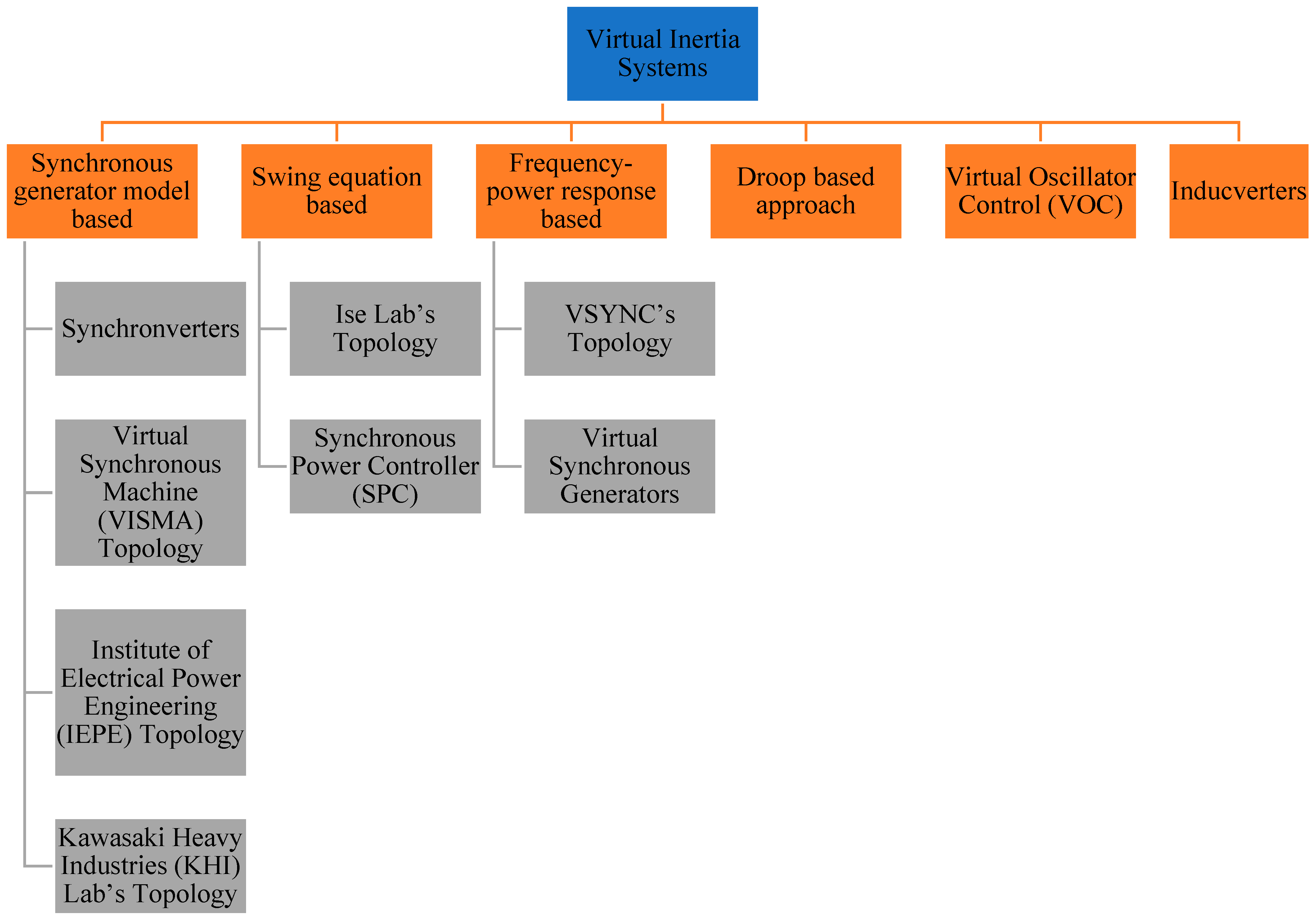
2. Current Virtual Inertia Topologies

The ROCOF in a power system network grows as the system inertia decreases, resulting in a bigger fluctuation in the frequency of the system. As new RESs are incorporated into the power system, the system will require greater inertia [11]. In 2007, Beck and Hesse presented the virtual-synchronous machine (VSM) technique [19], which uses power electronics to mimic some of the properties of synchronous generation and provides power system assistance. The VSM control approach has so far been established to regulate power converters to mimic the inertia and other features of the synchronous machine, in light of the growth in renewable production and the resulting reduction in power system inertia [20]. VSM can emulate the inertia of a conventional power network by an integrated approach of control algorithms, power electronics, RES, and energy storage devices [10,21,22]. Although the principle of modeling virtual inertia is similar for various topologies, the execution of each topological model is different. Some topologies use mathematical equations to emulate synchronous machine behavior, whereas a few topologies utilize swing equations to simulate the synchronous generator behavior [23]. Distributed generation (DG) units react to utility grid system frequency variations in a few topologies. This section covers a number of prominent VSM topologies. In the literature, many key topologies of VSM have been proposed, as shown in Figure 4 [6,23,24,25].

2.1. Topology Based on Synchronous Generator Model

2.1.1. Synchronverters

Synchronverters perform as an equivalent to a combination of an SG and a small-capacitor bank. Synchronverters control inverter-based DG units as SGs, which, from the grid’s perspective, depict the same dynamics. Synchronverters may be used as grid-forming units without making substantial modifications to their operating structure and are particularly well-suitable for inertia imitation from DGs that are not linked to the grid [26,27]. A frequency droop control algorithm regulates the inverter output power since the frequency derivative is not necessary when using this topology and there is less noise in the system. Furthermore, the moment of inertia and the damping factor may need to change to satisfy certain needs [6]. The overall schematic of the synchronverters is shown in Figure 5.
A synchronverter is made up of two parts: a power component, which is similar to the typical power electronic converter shown in Figure 6, and an electronic part, shown in Figure 7, which includes the sensing, protection, and control circuits, where D p is a damping factor, T e and T m are the electromagnetic and mechanical torques, and J is the moment of inertia [27].
The synchronverter uses the following equations to model SG behavior, as expressed in [6,18]:
T e = M f i f i , sin   θ ˜  
e = θ ˙ M f i f sin   θ ˜  
Q = θ ˙ M f i f i , cos   θ ˜  
where, M f represents the size of the mutual inductance between the stator coil and the field coil, i f represents the field excitation current, θ represents the angle between one of the phases of the stator winding and the rotor axis, e represents the no-load voltage generated, and Q represents the reactive power produced [18].
A three-phase cylindrical-rotor synchronous machine’s mathematical model is at the heart of the controller of a three-phase synchronverter, as illustrated in Figure 7. The back electromotive force, e , estimated using the mathematical model, is sent into a PWM generating block, which generates PWM pulses to operate the power semiconductors, as shown in Figure 6. The currents that flow out of the power stage’s inductors are counted as the stator current i and return into the mathematical model representation [6,23,26,27]. The synchronverter’s power part is the circuit to the left of the three capacitors, along with the capacitors. If we ignore the ripple, this section of the circuit will operate as an SG with the identical capacitors linked in parallel. Although the L g inductors are not part of the synchronverter, they are important for synchronization and power regulation. It is essential to include energy storage on the side of the dc bus because the power consumption from the dc bus reflects the power received from the fictitious prime mover and the inertia of the spinning component of the hypothetical SG. The latter component of electricity may arrive in large bursts, proportionate to the grid frequency’s derivative [27]. The synchronverter can reproduce the precise dynamics of an SG, yet the intricacy of the underlying differential equations might lead to numerical instabilities. Additionally, a voltage-source technique may need additional protection mechanisms for safe operation since it lacks inherent safety against powerful grid transients. This might be performed without making significant modifications to the operation’s structure [18].

2.1.2. Kawasaki Heavy Industries (KHI)

Instead of employing a complete dynamic model representation of the SG, the KHI topology implements an analogous model of a governor and automatic voltage regulator (AVR) in a discrete controller to produce the virtual machine’s voltage amplitude and phase reference. These references are employed to generate reference currents using the algebraic phasor representation approach for a synchronous generator, as shown in Figure 8 [18,28,29].

2.1.3. VISMA and IEPE Topologies

The virtual synchronous machine (VISMA) and Institute of Electrical Power Engineering (IEPE) approaches are two more topologies and techniques that have been introduced in various research works [23,30]. For all topologies, the basic principle of simulating an inertia response is the same. In the research effort of [30], the VISMA approach simulates the SG using d - q based architecture. When this architectural design is implemented using a digital control unit of a power converter, the dynamics of a synchronous generator are replicated. However, it has been suggested in the literature that the VISMA approach is unstable due to the use of numerical data. Using a three-phase model, a strategy is created to boost the strength. For asymmetrical loads and abrupt fluctuations in the utility grid, this novel approach is quite effective.
The IEPE topology is a topology that is similar to VISMA, but the main distinction is that IEPE uses the output current of a DG to provide a reference voltage for virtual machines. In the grid-linked mode of IEPE, dealing with transient currents during the synchronization phase is difficult. The IEPE approach, on the other hand, is best-suited for islanded mode [31].

2.2. A Swing Equation-Based Topology

2.2.1. Ise Lab’s Topology

This architecture resolves the power- and frequency-based swing equation in each control step to simulate inertia rather than needing a fully detailed description of the synchronous generator [18,32]. Figure 9 depicts a simplified example of this topology. From the common connection point, the frequency and power measuring equipment collects the voltage and determines the output current of the inverter. It makes an estimate of the utility grid frequency and the inverter’s active output power. The control algorithm unit receives prime mover input power as well as two computed values [23,32,33]. The control technique may be implemented without the need of a frequency derivative, much like a synchronverter. This is very beneficial since frequency derivatives are established to add disturbance into the system, making it challenging to control. This topology may also be utilized to run DG as grid-forming systems. However, there are still issues with numerical instability, which when combined with incorrect setting of the parameters J and D p , can cause oscillatory behavior of the system [18,33].
A SG’s typical swing equation is:
P in - P out = J ω m ( d ω m dt ) + D p Δ ω  
Δ ω = ω m ω g  
where, P i n and P o u t are the input and output powers (W), J is the moment of inertia (Kg· m 2 ), ω m is the virtual angular frequency (rad/s), D p is the damping factor (Kg· m 2 /s), and ω g is the reference value of the angular frequency (rad/s) [18,33]. The input power, P i n , is calculated using the governor model, as illustrated in Figure 10, where, P 0 is the DG unit’s continuous power reference. With gain K and a time constant T d , the governor is characterized as a lag element of the first order. However, as a result of the governor model’s delay, ROCOF is increased, which raises frequency nadirs [18].

2.2.2. Synchronous Power Controller (SPC)

The SPC, as presented in Figure 11, is another common topology for implementing virtual inertia. The control algorithm’s general structure is similar to that presented in the Ise lab’s architecture, nonetheless, the converter is not operated as a voltage- or current-controlled system; rather, with an inner current and outer voltage control loops, it uses a virtual admittance to build a cascaded control system [34,35,36]. In general, during severe transient operating circumstances, such system control offers intrinsic over-current protection. This feature is absent from other open-loop methods, including synchronverters and Ise Lab. SPC also eliminates the discontinuities that occur while solving mathematical models, resulting in a system that is more resistant to numerical instabilities.
The nested loop structure, on the other hand, makes setting the control system parameters more difficult. Furthermore, with an over-damped response, a second-order representation is provided as an alternative to employing the swing equation for inertia emulation. This helps to minimize the system’s oscillations [36]. The authors of [37] offered improved versions of this second-order model.

2.3. Inducverters

Another type of inertia simulation control technology is the inducverter. The inducverter’s principle is established mostly on an induction machine’s inertial characteristics. A self-starting and soft-starting induction machine is available. It has the ability to synchronize with the utility grid and follow changes to the utility grid. The inducverter uses the same principles to simulate inertia. An inducverter’s active power and frequency can be altered using power electronic inverter-based virtual rotor inertia [6,38]. An inverter with a filter makes up the electrical portion of the inducverter, along with a control portion that makes the inverter behave as an induction machine by generating the voltage signals, as illustrated in Figure 12. This approach offers the benefit of automatic synchronization without a phase-locked loop (PLL).

2.4. Virtual Oscillator Control (VOC)

Another VSM topology is the virtual oscillator controller (VOC), which synchronizes DG units devoid of any kind of communication by implementing a non-linear oscillator inside the controller rather than simulating SG or induction generators. This strategy is especially advantageous in a grid controlled by DGs, because the controller is capable of maintaining synchronism and sharing the overall system load [18,39].

2.5. Frequency–Power Response-Based Topologies

The easiest method of simulating inertia is to use a frequency–power response-based architecture [18]. This architecture is not incorporated into any synchronous generator modeling.

Virtual-Synchronous Generators (VSG)

The inertial responding properties of an SG in a DG network, particularly its capacity to adapt to frequency variations, are mimicked by virtual-synchronous generators (VSG). This simulates the kinetic energy’s production or absorbing in the same way as an SG does, allowing the DG units to be dispatched. The VSG technique, in contrast to classic droop controllers that simply allow frequency regulation, may offer frequency control. This control is based on the frequency measurement’s derivative and is similar to an SG’s inertial power generation or absorption in a power imbalance. As a result, the VSG, then, is a dispatchable distributed generation that adjusts its output in response to variations in system frequency. Since it does not include all the complicated equations needed in an SG, VSG is among the easiest ways to apply virtual inertia. Using several DG units as current sources, on the other hand, is known to cause instability. Equation (6) is used to adjust the VSG converter’s output power:
P VSG = K D Δ ω + K I ( d Δ ω dt )  
where, Δ ω is the change in angular frequency, d Δ ω d t is rate-of-change in angular frequency, K D is the damping constant, and K I is the inertial constant. The ROCOF is stopped by the inertial constant, and this, based on the frequency derivative, provides a quick dynamic frequency response. In an isolated grid, this functionality is particularly critical, given that the initial ROCOF might be quite large, causing protective relays to be unnecessarily triggered. Figure 13 depicts the structure of the VSG. The system frequency change and ROCOF are measured using a PLL. For the inverter, the active power reference is then calculated using Equation (6). On this basis, references for the current controller are created [40].
The architecture shown here uses a direct and quadrature axis d - q current control method, although any alternative current control method can be employed. The d-axis current reference for d - q control may be computed as:
I * d = 2 3 ( V d P VSG - V q Q V d 2 + V q 2 )  
where V d and V q are the d q parts of the observed grid voltage, v , respectively. As the active power is regulated only, the q-axis current reference, I q , and the reactive power, Q , are both set to zero. The gate signals to operate the inverter are produced by the current controller, which is established on grid current feedback. As a result, the inverter functions as a voltage source inverter with current control.
Another sort of VSG used to simulate the inertial features of an SG is the VSYNCH’s VSG. It can respond to variations in frequency. The block diagram of the VSYNCH’s VSG is presented in Figure 14. In the inertial response, the control method creates a control signal to add, from the storage device, the needed quantity of power. The VSG acts as a current control source, simulating inertia. The PLL is built in such a way so that it produces the ROCOF and Δω in this case [6].

2.6. Droop-Based Approaches

To increase inertial responsiveness of inverter-dominated power systems, the techniques reported until now attempt to emulate or simulate the SG’s performance. For the autonomous functioning of isolated microgrid systems, frequency droop-based controllers have been created [18], which differ from existing strategies. The frequency droop is accomplished as follows, assuming that the grid’s impedance is inductive:
ω g = ω *     m p ( P out     P in )  
where P i n represents the active power reference, P o u t represents the DG unit output measured active power, m p represents the active power droop, ω * represents the reference frequency, and ω g represents the local grid frequency. The voltage droop is implemented in the same way:
v g = v *     m q ( Q out     Q in )  
where, v * represents the reference voltage, v g represents the grid voltage, Q i n represents the reference reactive power, Q o u t represents the DG unit output measured reactive power, and m q represents the reactive power droop. Figure 15 depicts the architecture of the method based on Equation (8). To measure the inverter output power and to attenuate high-frequency parts from the inverter output, a low-pass filter with a time constant T f is frequently employed [18]. The filters employed in these controllers for power measurements create a delay that is mathematically comparable to the virtual inertia, whereas the droop gain is comparable to damping. Conventional droop-based systems, such as those explained in (8) and (9), are known to possess a delayed transient reaction. There have been suggestions for ways to enhance droop controllers, by employing virtual output impedance or increasing the dynamic performance of the droop structure.
Finally, Table 1 summarizes the key features of each VSM topology. The summary highlights the key information of each topology. Virtual inertia models built on synchronous generators have the advantage of being an exact copy of synchronous generator dynamics. In a synchronous generator-based approach, PLL is used for phase synchronization and frequency derivatives are not necessary. These topologies lack over-current protection and have numerical instability as drawbacks. In contrast to SG-based models, swing equation-based models are easier to understand. PLL is only utilized for phase synchronization in these topologies, and frequency derivatives are not necessary. Power and frequency fluctuations as well as a lack of over-current safety are some of these topologies’ drawbacks. The construction of the frequency–power approach-based model, on the other hand, is simple since it uses a standard current-source implementation and includes built-in over-current protection. Due to PLL, these topologies are insecure, most often in weak grids. The frequency–power method is a model that is subject to noise.

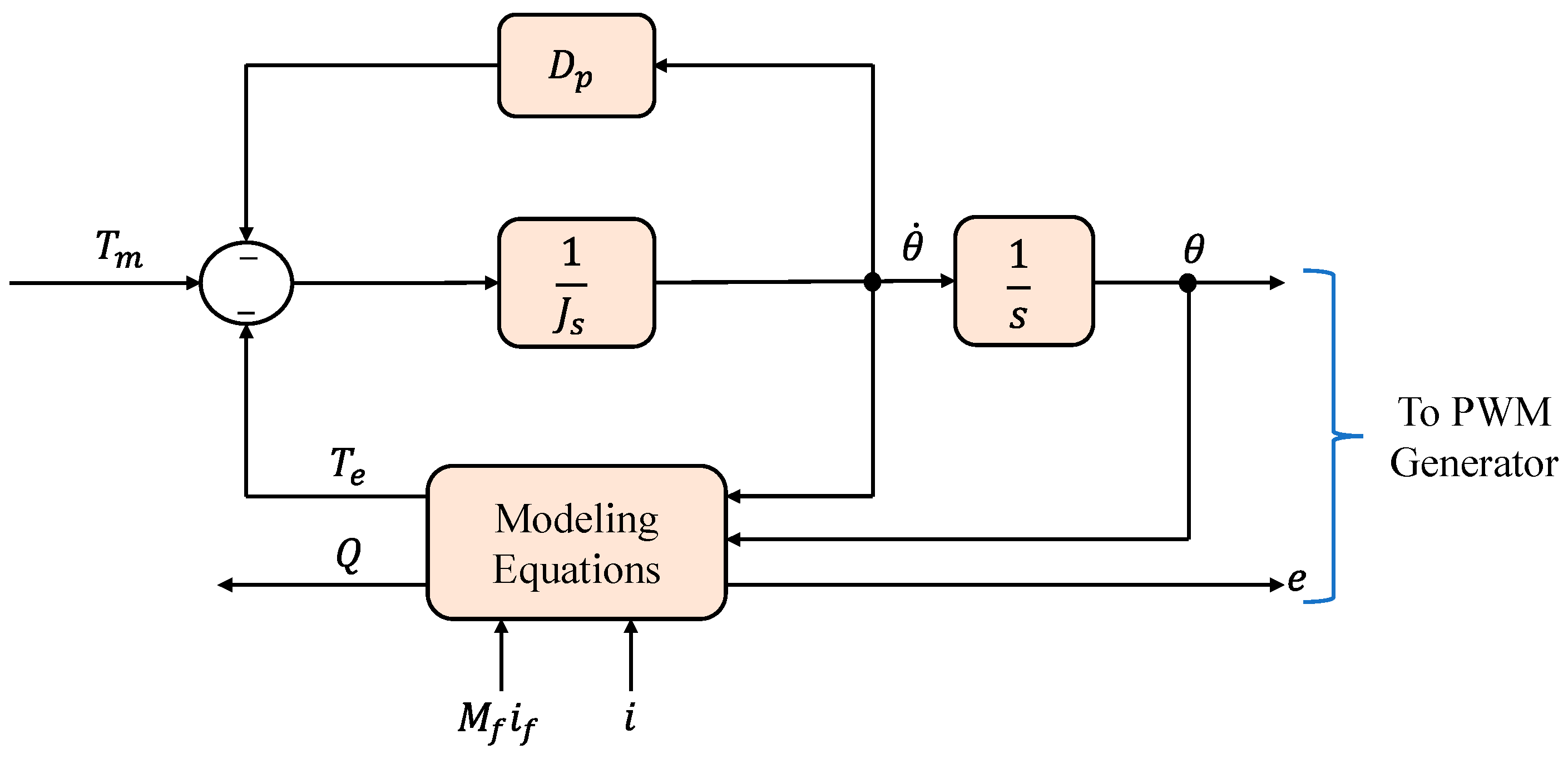
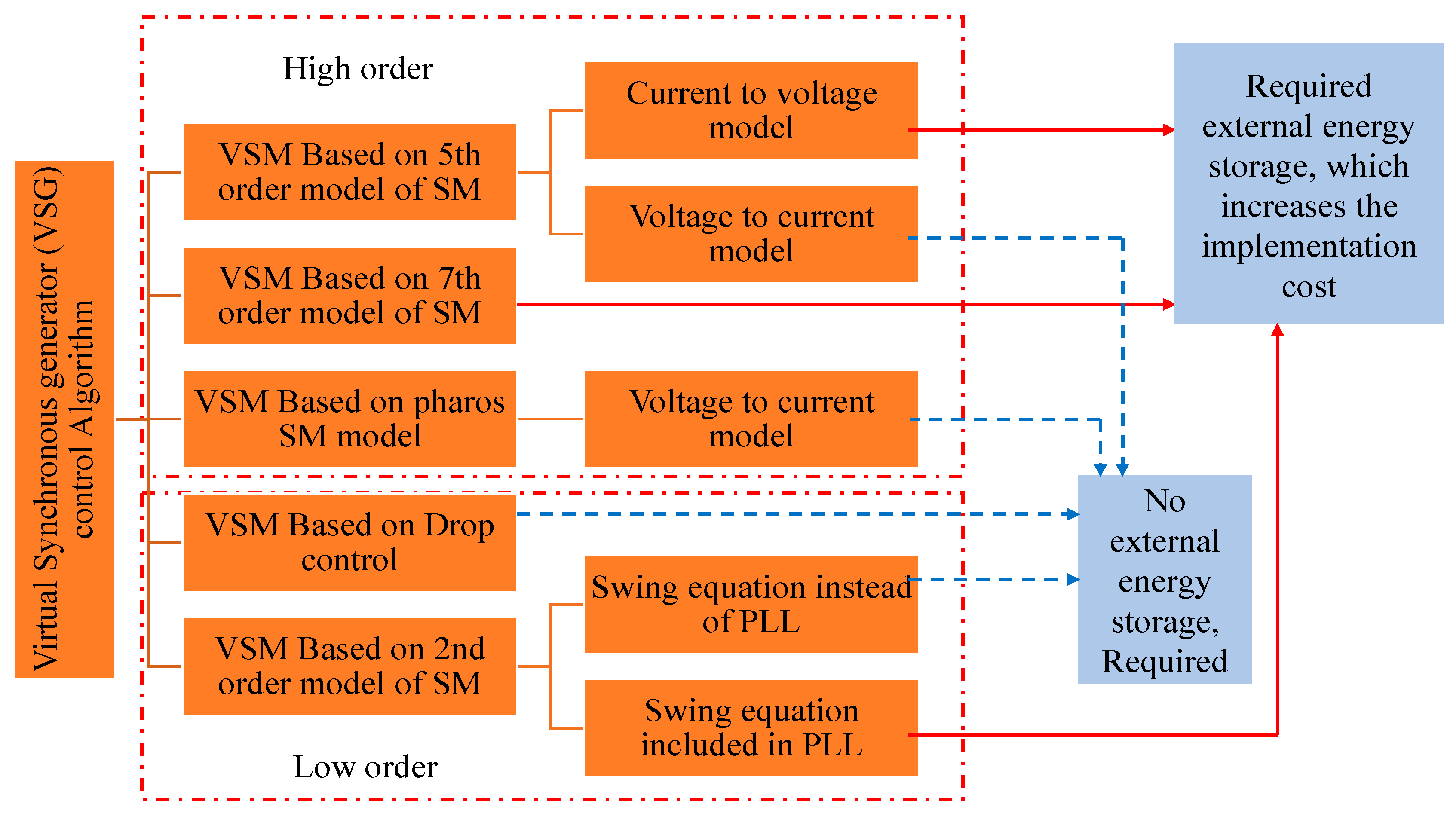
3. Virtual-Synchronous Generator (VSG) Principles and Control Orders

VSG has a basic and very simple construction [23], as illustrated in Figure 16, which contains a filter circuit, DG system, storage unit, DC/AC converter, governor, and a grid. If the input torque of the prime mover is considered the power of the DG unit and energy storage device, and it is presumed that the electromechanical energy transfer between the rotor and stator is the DC/AC converter. The electromotive force of the VSG is represented by the fundamental component of midpoint voltage. The stator winding impedance is represented by the filter’s inductance and resistance [23,41].
The voltage and current on the AC side of the inverter, displayed in Figure 16, are v a b c and i a b c , respectively. The filter voltage and current are v o a b c and i o a b c , respectively. The grid voltage is v g a b c , while R , L f , and C f are the resistance, inductance, and capacitance of the filter, respectively. The gridline inductance is L g , the VSG internal voltage amplitude is E, the phase difference is δ, the voltage magnitude and phase of VSG terminal are V and θ, and the active and reactive power output by VSG are P e , P m and Q e , Q m , respectively. The higher-order and lower-order VSG control techniques may be established by making minimal changes to the voltage source controller’s control structure. Despite that both types of VSG strategies regulate active and reactive power, every approach has its own control structure. Furthermore, numerous VSG control algorithms have been devised for a power electronic converter to replicate the properties of an SG [23,42,43]. Furthermore, models of VSG can be split according to the need for an additional component, such as energy storage; hence, Figure 17 summarizes the distinctions between VSG models at various phases, as discovered in the literature [42].

3.1. VSM Model with High Order

By including effective inertia and damping ability into the VSC control algorithm and utilizing the mathematical model of SM, it is possible to emulate the characteristics of SM inertia [42]. The reference values are calculated using the SM’s high-order model. It is worth noting that SM’s mathematical model includes both electrical and mechanical components. The mechanical portion is in charge of creating the swing equation. There are two versions of the high-order VSG control method. The first configuration is a voltage-to-current one, and it is based mostly on detecting the point of common coupling of AC voltages. The second configuration is a current-to-voltage model with energy storage. As shown in Figure 18a, the voltage-to-current model offers set point values of current to manage the VSC, whereas the current-to-voltage model gives reference voltage values, as illustrated in Figure 18b [42,44]. In [44], an evaluation of both VISMA high-order models was conducted during typical operating conditions using distinct switching strategies.

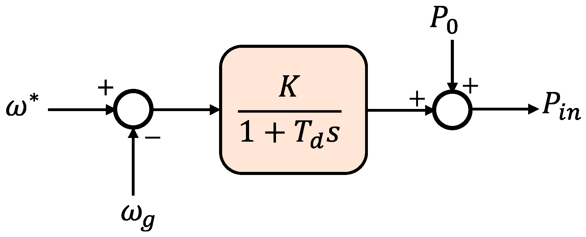
3.2. Model of Low-Order VSM

The features of the high-order VSM model outlined earlier are similar to those of SM. The low-order VSM control technique, on the other hand, is comparable to the traditional droop technique, which is based on the swing equation, as illustrated in Figure 19. The replication of the inertia and damping behavior of SMs may be obtained by employing the swing equation because the major goal behind adding VSM is to emulate SM behavior. As a result, torque parameters are used to express the general version of the SM swing equation based on Newton’s law, and it may also be represented in terms of real power in a situation of executing VSM control [42].
The major distinction between the high- and low-order VSM control methods is the regulated topology of the VSC. Despite that both low-order and high-order VSM algorithms provide real and reactive power regulation separately, and each of them has a unique control framework, both control orders in VSM algorithms undoubtedly imitate the inertia and damping behavior of SM since the swing equation is presented in the control approach. It is still unclear which of the control order options is the most efficient. As a result, the work in [42] provides a complete comparison of VSM order control methods to provide unambiguous advice on which VSM method to choose [42]. The authors found that the low-order VSM control method is clearly extra dependable compare to the high-order VSM control method. Furthermore, utilizing a high-order model to regulate VSC and simulate inertia may cause numerical issues because of the use of AC voltage measurements, which is not optimal. An unstable AC voltage was used to test the stability of both control methods. Clearly, the most promising method is the low-order VSM based on a frequency–power droop technique controller since it also stays stable when electrical distribution systems are subjected to aberrant conditions. Moreover, the low-order VSM’s cascaded voltage and current management protects the converter against overloading difficulties, and it features a function that may limit the direction of power flow [42].

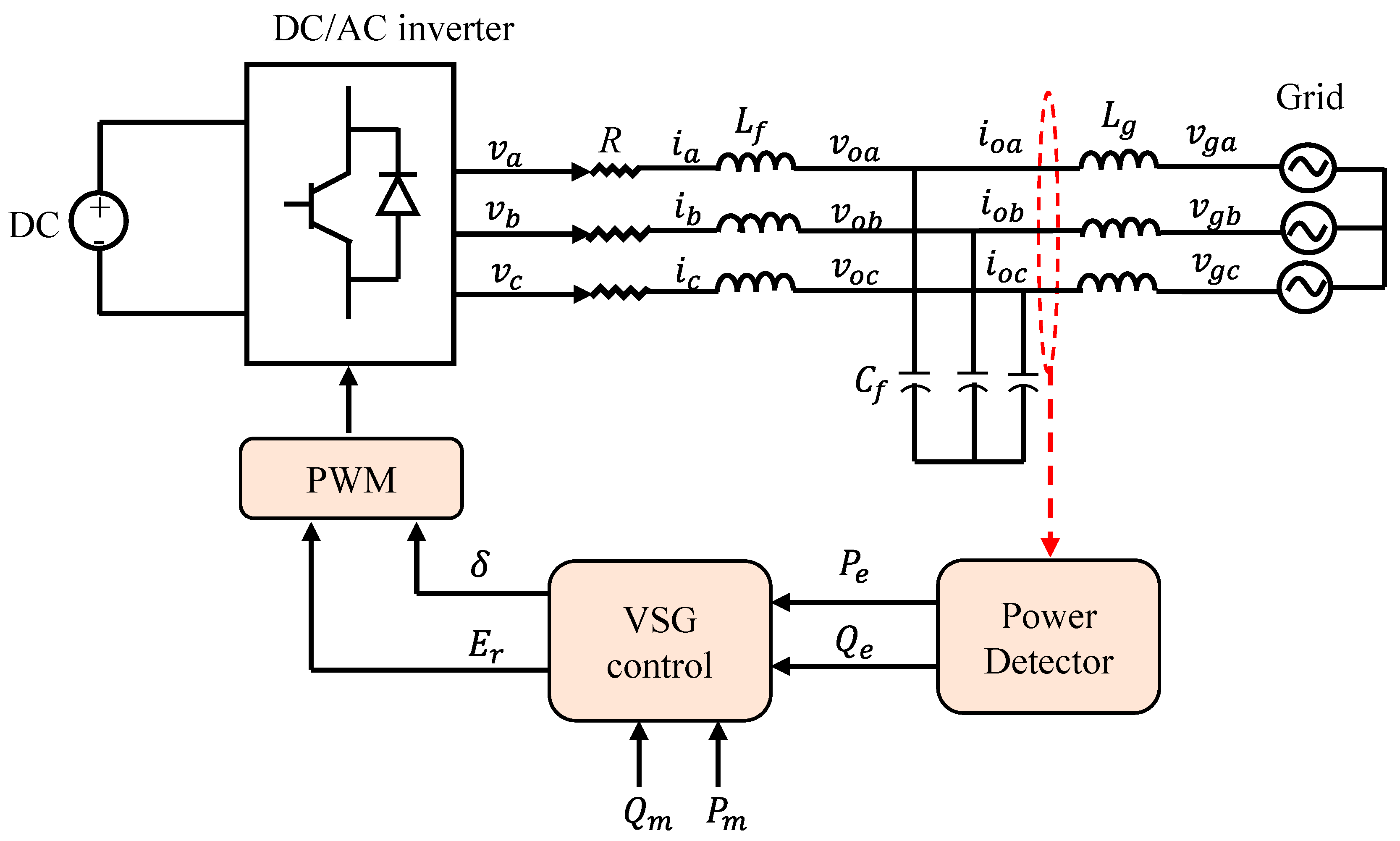
4. VSG Operation Control

The appropriate operating mechanism of the inverter at its interface allows VSG to control its input/output. Typical control approaches include real and reactive power control, voltage and frequency control, and a droop controller. The deployment of the control strategy into the system is often dependent on the power system’s operational mode. The sole difference between a regular inverter and a VSG is that the VSG replicates the features of an SG through its control algorithm. VSG’s control algorithm may be separated into two types, which are detailed as follows [23,41].

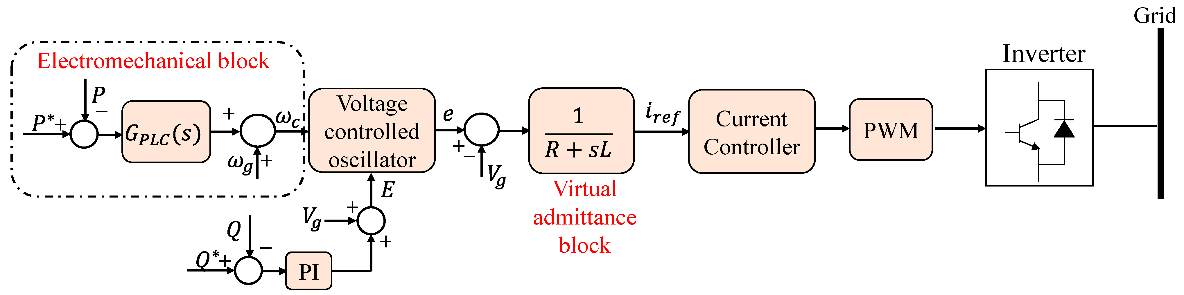
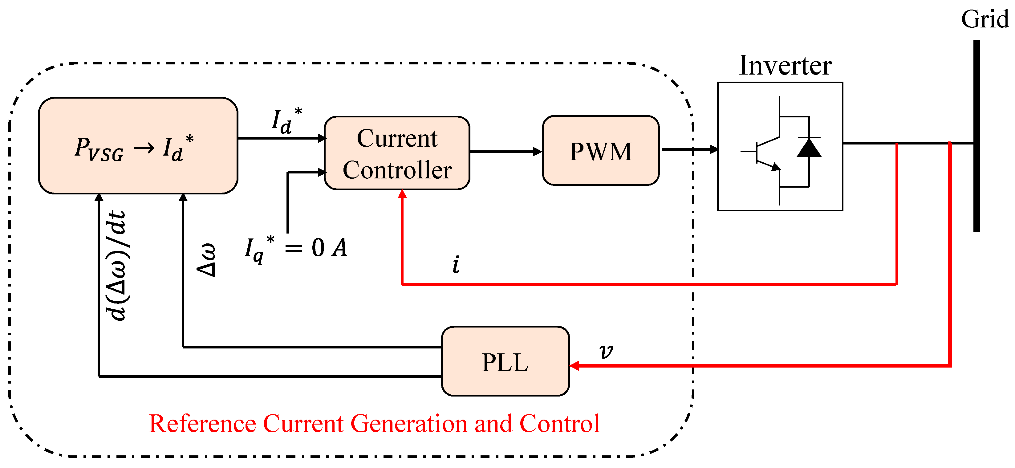
4.1. Active and Reactive Power Controls

The outermost power loop and the inner current loop make dispersed generators’ output a constant scheduling power through real and reactive power control. This control mechanism is generally employed in grid-connected VSG units. In the power system, the converter’s active and reactive power control work as control buses. The majority of the buses in the power grid system are control buses. Active and reactive control buses are the most prevalent storage devices for electric cars. When the active and reactive power techniques are used in grid-linked mode, active power can closely follow the governor unit’s dispatch instruction. However, the reactive power controller does not properly follow the dispatch instruction and fails to supply the system with the requisite reactive power. VSG’s active power control is a duplicate of SG’s governor unit. Figure 20 shows the control diagram, with P e and P m representing the VSG real power and reference active power, respectively [23,41,45,46].
Due to its simplicity, most VSG control systems now employ the active and reactive power control method. Work in [47] presents a new frequency control technique for electric vehicles (EVs) to support in main and secondary microgrid frequency management. A virtual-synchronous generator with AC/DC control is utilized to introduce effective inertia and damping characteristics. As a result, the charging/discharging device possesses inertia and damping characteristics comparable to an SG. A fuzzy controller based on the VSG architecture to attenuate disturbance throughout transients by enhancing the system’s inertia is proposed in [48]. The suggested fuzzy control boosts the system inertia during transients by adding a corrective term to the output power of the governor. On a VSG platform, the difference between the suggested fuzzy-based control approaches and the cost function-employed optimization for inertia and damping coefficients are performed to compare the improvement of the inertial response. Compared to other time-consuming strategies, online measurement-based adaptive systems offer a greater inertial response. In [49], according to a comparison of standard droop control and VSG control, a general droop control (GDC) for a grid-forming inverter is presented in this study. Moreover, in [50], an enhanced droop control technique integrating coupling compensation and virtual impedance is suggested to increase the microgrid’s efficiency and stability.

4.2. Voltage and Frequency Control

In this control technique, the current inner loop and the voltage outer loop of the voltage and frequency control may output constant voltage and frequency. This is a common control method in islanding VSG units. During the islanding operation, the primary control unit provides voltage and frequency assistance for the passive unit as a slack bus, employing active and reactive power regulation. This technology has a high-speed feature that makes it excellent for use in solar and wind energy-generating and storage systems. By mimicking the SG’s function excitation regulator, the VSG’s voltage control unit accomplishes the voltage amplitude. In general, the voltage control adjusts the output voltage according to the amplitude deviation of the VSG output voltage and utilizes the voltage adjustment coefficient, K q , to characterize the VSG’s voltage regulation capabilities. Figure 21 depicts the principal control framework for voltage control and reactive power regulation. In Figure 21, V o and V r represent the actual and reference voltages, respectively. The computed reactive power is Q e and the set point reactive power is Q m . The reactive voltage droop coefficient and the integral coefficient are K q and K E , respectively. E r is the amount of the reference output voltage. To make a VSG voltage reference, the amplitude of the reference output voltage is paired with the angle of active frequency control [23,41,46].
Voltage and frequency control using an interleaving method provides self-adaptive inertia and damping to increase the stability of the frequency [50]. The suggested method’s efficiency is demonstrated by tests on the MATLAB/Simulink VSG model. In [43], under unbalanced voltage situations, a comprehensive VSG control approach is provided. Experimental and simulation results are utilized to confirm the validity and efficacy of the suggested control approach. Self-adaptive VSG is a relatively recent frequency support control technology for VSG power systems. The inertia of a non-adaptive VSG-based power network is constant, and the use of different inertia values has a considerable effect on the stability of the frequency. The self-adaptive VSG approach is presented in order to suppress these difficulties [51,52]. In [52], a fuzzy-based, self-adaptive, virtual inertia controller is developed to ensure steady stability of frequency. This control approach updates the virtual inertia constant based on real power injection from renewable energy sources and system frequency changes, thus preventing inappropriate selection, and affording a speedy inertia response. The simulation findings demonstrate that applying self-adapting VSG significantly improves frequency stability; nonetheless, the article lacks experimental results. As a result, simulation findings are only reported for a single islanded microgrid, with no discussion of outcomes for several VSG-based islanded microgrids.
Furthermore, in [53], virtual inertia enhancement using a novel, optimum, robust control technique is developed to improve the modern power systems’ frequency stability while taking into account impacts of frequency measurement, nonlinearities, and renewable intermittencies. To collect the estimated system frequency information, a PLL is needed when using the virtual inertia control approach [53].

5. Virtual Inertia (VI) Control Strategies

Various VI-based inverter control approaches have been constructed and developed to enhance power quality, tracking of inverter output voltage or current, and disturbance rejection. Different types of controllers can be used to build grid-following and grid-forming inverters. The controller optimizes and manipulates the voltage or current to create inverter PWM. The most prevalent control approach for VI-based inverters is inner-loop voltage and current control. Based on the peculiarities of inverter architectures, several established control mechanisms are applied. Straightforward approaches to complicated mathematical procedures are used to construct control systems. In general, the most often utilized control approach is a proportional integral derivative (PID). However, it has a number of serious flaws, including performance decrease during the disruption [10].
Recent work on approaches for controlling virtual inertia in islanded microgrids is discussed in [54]. Some of the methodologies examined included the coefficient diagram techniques, particle-swarm-based techniques, fuzzy-logic-based techniques, H-infinity-based techniques, model-predictive controllers, and reinforcement learning-based techniques, and these methodologies are shown in Table 2 [54].
Furthermore, in [5,20,46,55,56,57,58,59,60,61,62,63,64,65,66,67,68], the use of various control strategies and their effects on VI are investigated. In [55], a new control method for an isolated PV-Diesel hybrid power plant using virtual synchronous generators is proposed for output voltages’ synchronization with no need for a PLL, and meanwhile adjusting the starting position of the diesel generator’s rotor and assuring that the two sources are sharing power in accordance with the specified power ratio. In [56], an energy storage system (ESS)-based new VSG using model-predictive control (MPC) is developed to minimize irregularities and improve the MG’s stability. During transient states, the suggested approach may offer inertia support and improve the dynamic system voltage and frequency characteristics. The research in [57] proposes a new VI control technique. An in-depth analysis on the lack of agreement between the VI concept and the energy storage control algorithm is performed in conjunction with the potential inertia benefits of the VSG technique. To increase control precision, the paper focuses on analyzing the frequency response properties of the alternating current (AC) side. This research regulates the ac frequency more precisely and directly using the virtual inertia produced by the ESS and the grid-connected inverter. The work in [58] provides a unique VSG-based multi-loop control method for managing integrated inverter-based renewable DGs in a plug-and-play way. In this multi-loop control approach, the virtual flux-oriented controller is used to eliminate harmonic intrusion and make sure that the voltage/current closed-loop feedback-based vector control system correctly manages the vector orientation process. The VSG-based control is capable of obtaining a quick current response and stable output voltage tracking control with no errors. A fast-responding external energy reserve is employed in [59] to regulate the frequency of a microgrid under transient situations. With a virtual synchronous machine, the weak grid properties are researched and modeled. To connect the ESS to the grid, an inverter model is designed, as well as a dual second-order generic integrator PLL that can synchronize the system in inaccurate and imbalanced situations. A novel method for estimating the microgrid’s frequency is described. Furthermore, the work in [60] focuses on the economics of resource inertia as a grid service, with the goal of determining a low-cost commitment of fast-acting storage devices to improve primary frequency responses. In [61], the inertia needed from ES systems during a generation transition is calculated using an analytical approach. The work in [62] introduced a new microgrid control approach that incorporates a model-predictive control (MPC)-based virtual inertia technology to simulate virtual inertia in the microgrid control loop, therefore steadying microgrid frequency. In [5], an intelligent and autonomous connection strategy for DC microgrids into the established ac grid is presented based on the VSM idea. In [46], a control technique of a VSG is provided to increase the system’s frequency stability. For a microgrid, an enhanced bang-bang control strategy-based adaptive virtual inertia control method is introduced. In [63], Gray-box system identification is used to perform the equivalence between the VSM-based microgrid (VSMG) small-signal model and a revised third-order model of SG, which is accomplished by alternately and repeatedly estimating equivalent electrical parameters. Variable-speed wind turbines can use the synchronverter and inertial control method in [64]. Furthermore, a complete evaluation of frequency-based inertial control and synchronverter inertial controls was performed using a model of a type 4 permanent magnet synchronous generator-based wind power generation system. The work in [65] examined the effect of damping and moment of inertia on the system, using a comparative relation between the synchronous machine and three-phase inverter’s, as well as the rotor motion equation of the VSG. This study also uses the small-signal model and root locus to perform stability analysis. Based on the current control technique, a VSG cooperative control approach based on the ideal damping ratio was developed. In [66], the research then proposed an adaptive control technique according to the findings of the parameter evaluation. In another work, in order to increase the dynamic performance and decrease the reactive power-sharing error in a low-inertia microgrid, the study in [67] proposed enhanced VSG control algorithms. The frequency response and stability of three parallel VSG-based photovoltaic systems combined with battery energy storage are investigated in [20]. Furthermore, the best values of the droop controller parameters utilized in VSG are obtained using an advanced genetic algorithm optimization approach. In addition, two separate situations involving variations in the system’s supply and load power are thoroughly examined. In order to simulate both damping and inertia characteristics concurrently for the microgrid and improve frequency stability and performance, the work in [69] proposed a unique analysis and design of VI control. To compute the frequency derivative for VI imitation, the suggested virtual inertia control employs the derivative approach.

6. Energy Storage

Battery energy storage systems (BESSs) might be utilized to simulate the inertial reaction of synchronous generators, such as the virtual-synchronous generators. Virtual inertia refers to the idea of simulating inertia in which the reaction to disturbances in the power grid is unconnected from the power generation. This can be carried out by adding a second control to the power electronic interface that regulates power output or installing an energy storage device to help supplement the power that is currently being injected into the power system [70]. The energy required to manage the active power output is provided by the storage [71,72,73]. For small power networks with low inertia, ESS is vital and significant [73]. Work in [74] introduces several modes of BESS management with varying grid consequences, such as correcting the inertia and main frequency response’s performance. An energy storage system may be employed to enhance power flow control. However, the amount of energy required for this service does not necessitate the need of an energy storage device if the power plant only offers inertial support. Furthermore, a battery storage system’s existence might be considered during the VSG tuning phase by depending on the storage capacity, choosing the inertial constant. The capacity of the storage system for main and secondary frequency control is determined by the plant’s management strategy and any contractual agreements with the transmission system operators (TSO) [75]. Energy support for inertia and main frequency regulation of VSG can be provided by a variety of energy storage technologies, including batteries, flywheels, supercapacitors, and superconducting magnetic energy storage [76]. Table 3 summarizes the essential properties of various energy storage systems.
When choosing energy storage units for an ESS, high-energy density units should be utilized in conjunction with high-power density units to improve system operational efficiency and/or lifetime while lowering system costs. The hybrid energy storage system battery/ultracapacitor (HESS), as an example, uses the battery to compensate for low-frequency power variations, while the ultracapacitor compensates for high-frequency power fluctuations [77]. The master–slave and peer-to-peer control techniques of the active power reserve, where the reserve power is employed as the inertia power and primary frequency modulation (FM) power, are offered as different approaches to achieving the maximum power point (MPP) of PV power plants in [78]. A general approach for optimally dimensioning a BESS device utilized for frequency regulation in a standalone power system was demonstrated in [79]. The ideal solution was achieved through the use of a dynamically changeable state of charge restrictions and a suitable device size.

7. Future Research Scope

RESs are rapidly expanding and integrating. Therefore, in the past years, there has been a major advancement in VSG regulation and associated techniques. The creation of VSG offers a practical and affordable way to use renewable energy sources and expands the opportunities for their use. Furthermore, the rising integration of VSG into the power system indicates that a sizable portion of the future power system will include both traditional SGs and a large number of VSGs. As a result, more research needs to be carried out on coordinated control between VSGs and traditional SGs during different operational modes and fault conditions.
The best distribution of renewable energy resources may be achieved by ensuring that VSG and SG effectively interact. As a relatively new technology, the VI inverter has a lot of space for development and advancement. Moreover, regarding the VSG control methods, due to its conventional design and slower transient response, the traditional controller is anticipated to be replaced within the next few years by a new generation of VI inverters with an improved controller. The algorithm is changing from a traditional controller to an intelligent and adaptive one, such as model-predictive control (MPC) and artificial intelligence (AI) control, including fuzzy-logic controllers. Digital stochastic control is a robust control approach that has been studied for power system applications [76]. This control approach can be investigated for virtual inertia emulation for stochastically varying renewable energy sources. Therefore, more studies on the VSG control design techniques employing intelligent controllers are required to achieve efficient and improved power sharing among the inverter-interfaced VSG.
High penetration of renewables using VSG mandates to investigate the reliability, energy security, and system stability from a utility point of view. Multilevel power electronic converters with appropriate control techniques can be investigated to maintain a minimum level of harmonic injection and other grid codes provided by the TSO [80]. This also triggers to examine the appropriate size of the VSG required for a power system network to ensure inertia support for a particular duration. Various optimization techniques can be utilized to determine inertia support duration for a given size of the VSG. In addition, economic aspects of this technique to tackle the rate of change of frequency issues in modern power systems need to be investigated.
Performance of VSG highly depends on the measurement, detection, and computing algorithms. Advanced computing algorithms, and accurate and fast detection and measurement of the rate of change in frequency, are essential for a wide range of uses of VSG. Therefore, massive research can be conducted using different signal processing techniques, such as wavelet theory, and machine learning techniques to attain optimal performance of the VSG deployment [81]. In addition, a high penetration level of VSG requires revisiting the system modeling for performance analysis and reliability and stability studies.
Although deregulation policies are in place, policies regarding reserve margin and technology to be deployed are yet to be developed in case of high levels of VSG penetration. Hybridization of energy storage can provide high-energy density and fast response solutions, which are required for virtual inertia applications. Therefore, further investigation into energy storage units is also required to obtain novel solutions to respond to the demands of virtual inertia in future power networks. Table 4 provides a summary of potential hybridization of various energy storage technologies in order to mitigate different issues [82].

8. Conclusions

The mismatch of converter-based non-dispatchable renewable energy production affects grid frequency stability as RES has been integrated more and more over time. Thus, VI-based inverters are created to provide an inertial response through the imitation of SM, thereby regulating the frequency of future power systems. Under conditions of substantial RES penetration, grid support via power converters is required.
This study presented an insightful description of the VSG structure and an overview of several topologies for virtual inertia. The overview drew attention to the essential details of each topology. At the same time, synchronous generator-based virtual inertia models have the benefit of being a precise replica of synchronous generator dynamics. On the other hand, the disadvantages of the synchronous generator-based technique include a lack of over-current protection and numerical instability. Swing equation-based models are more straightforward to understand than SG-based models. These topologies’ shortcomings include power and frequency variations and a lack of over-current protection. On the other hand, the frequency–power approach-based model employs a conventional current-source implementation and has built-in over-current protection, making its construction straightforward. These topologies are unsafe due to PLL, mostly in weak grids. The frequency–power approach is also a noisy modeling technique.
Additionally, a detailed explanation of VSG control was provided, including active and reactive power regulation as well as voltage and frequency control. According to the desired design, the appropriate VI-based inverter topology may often be chosen. The parameters for selection depend on whether a current source or voltage source is being used, as well as the amount of equation order that is required to accurately simulate SG behavior.
High-level penetration of renewable power involves multi-energy units and multifunctional power conditioning stages. To achieve stable, reliable, uninterruptable, and efficient power delivery in the network, coordinated control and monitoring are critical. Such an issue can be solved using advanced techniques, such as machine learning and blockchain technologies, and advanced power electronic topologies, such as multilevel modular power converters.

Author Contributions

Conceptualization, R.A.; methodology, M.S.; software, M.S.; validation, R.A., R.S.A., A.A.-B. and M.A.; formal analysis, R.A.; investigation, R.A. and M.S.; resources, M.S.; data curation, M.S.; writing—original draft preparation, M.S.; writing—review and editing, R.A., R.S.A., A.A.-B. and M.A.; visualization, M.A. and M.J.; supervision, R.A. and R.S.A.; project administration, R.A. and R.S.A.; funding acquisition, R.A. and R.S.A. All authors have read and agreed to the published version of the manuscript.

Funding

This research was funded by the Sustainable Energy Research Center (SERC) at Sultan Qaboos University (SQU) under grant number IG/DVC/SERC/22/01.

Conflicts of Interest

The authors declare no conflict of interest.

Abbreviations

The following abbreviations are used in this manuscript:
AI Artificial intelligence
AVR Automatic voltage regulator
BESSs Battery energy storage systems
DER Distributed energy resources
DG Distributed generation
ESS Energy storage system
FM Frequency modulation
GDC Generalized droop control
HESS Hybrid energy storage system
IEPE Institute of Electrical Power Engineering
KHI Kawasaki Heavy Industries
MPC Model predictive control
MPPT Maximum power point tracking
PCC Point of common coupling
PLL Phase-locked loop
PV Photovoltaics
PWM Pulse width modulation
RES Renewable energy sources
ROCOF Rate of change of frequency
SG Synchronous generator
SM Synchronous machine (SM)
SOC State of charge
SPC Synchronous power controller
TSO Transmission system operators
VI Virtual inertia
VSG Virtual-synchronous generator
VSM Virtual synchronous machine
VSMG VSM-based microgrid
VOC Virtual oscillator controller

References

  1. REN22, R. Global Status Report, 2022. 2022. Available online: https://www.ren21.net/ (accessed on 21 October 2022).
  2. Edrah, M.; Lo, K.L.; Anaya-Lara, O. Impacts of high penetration of DFIG wind turbines on rotor angle stability of power systems. IEEE Trans. Sustain. Energy 2015, 6, 759–766. [Google Scholar] [CrossRef] [Green Version]
  3. Kahani, R.; Jamil, M.; Iqbal, M.T. Direct Model Reference Adaptive Control of a Boost Converter for Voltage Regulation in Microgrids. Energies 2022, 15, 5080. [Google Scholar] [CrossRef]
  4. Fernández-Guillamón, A.; Gómez-Lázaro, E.; Muljadi, E.; Molina-García, Á. Power systems with high renewable energy sources: A review of inertia and frequency control strategies over time. Renew. Sustain. Energy Rev. 2019, 115, 109369. [Google Scholar] [CrossRef] [Green Version]
  5. Chen, D.; Xu, Y.; Huang, A.Q. Integration of DC microgrids as virtual synchronous machines into the AC grid. IEEE Trans. Ind. Electron. 2017, 64, 7455–7466. [Google Scholar] [CrossRef]
  6. Ratnam, K.S.; Palanisamy, K.; Yang, G. Future low-inertia power systems: Requirements, issues, and solutions-A review. Renew. Sustain. Energy Rev. 2020, 124, 109773. [Google Scholar] [CrossRef]
  7. Hossain, M.A.; Pota, H.R.; Hossain, M.J.; Blaabjerg, F. Evolution of microgrids with converter-interfaced generations: Challenges and opportunities. Int. J. Electr. Power Energy Syst. 2019, 109, 160–186. [Google Scholar] [CrossRef]
  8. Shah, R.; Mithulananthan, N.; Bansal, R.; Ramachandaramurthy, V. A review of key power system stability challenges for large-scale PV integration. Renew. Sustain. Energy Rev. 2015, 41, 1423–1436. [Google Scholar] [CrossRef]
  9. Bajaj, M.; Singh, A.K. Grid integrated renewable DG systems: A review of power quality challenges and state-of-the-art mitigation techniques. Int. J. Energy Res. 2020, 44, 26–69. [Google Scholar] [CrossRef]
  10. Yap, K.Y.; Sarimuthu, C.R.; Lim, J.M.-Y. Virtual inertia-based inverters for mitigating frequency instability in grid-connected renewable energy system: A review. Appl. Sci. 2019, 9, 5300. [Google Scholar] [CrossRef] [Green Version]
  11. Hartmann, B.; Vokony, I.; Táczi, I. Effects of decreasing synchronous inertia on power system dynamics—Overview of recent experiences and marketisation of services. Int. Trans. Electr. Energy Syst. 2019, 29, e12128. [Google Scholar] [CrossRef]
  12. Chown, G.; Wright, J.G.; Van Heerden, R.P.; Coker, M. System inertia and Rate of Change of Frequency (RoCoF) with increasing non-synchronous renewable energy penetration. In Proceedings of the 8th CIGRE Southern Africa Regional Conferenc, Cape Town, South Africa, 14-17 November 2017. [Google Scholar]
  13. Milano, F.; Dörfler, F.; Hug, G.; Hill, D.J.; Verbič, G. Foundations and challenges of low-inertia systems. In Proceedings of the 2018 Power Systems Computation Conference (PSCC), Dublin, Ireland, 11–15 June 2018; pp. 1–25. [Google Scholar]
  14. Mandal, R.; Chatterjee, K. Virtual inertia emulation and RoCoF control of a microgrid with high renewable power penetration. Electr. Power Syst. Res. 2021, 194, 107093. [Google Scholar] [CrossRef]
  15. Modi, N.; Yan, R. Low inertia power systems: Frequency response challenges and a possible solution. In Proceedings of the 2016 Australasian Universities Power Engineering Conference (AUPEC), Brisbane, Australia, 25–28 September 2016; pp. 1–6. [Google Scholar]
  16. Rahman, M.S.; Oo, A. Distributed multi-agent based coordinated power management and control strategy for microgrids with distributed energy resources. Energy Convers. Manag. 2017, 139, 20–32. [Google Scholar] [CrossRef]
  17. Rangu, S.K.; Lolla, P.R.; Dhenuvakonda, K.R.; Singh, A.R. Recent trends in power management strategies for optimal operation of distributed energy resources in microgrids: A comprehensive review. Int. J. Energy Res. 2020, 44, 9889–9911. [Google Scholar] [CrossRef]
  18. Tamrakar, U.; Shrestha, D.; Maharjan, M.; Bhattarai, B.P.; Hansen, T.M.; Tonkoski, R. Virtual inertia: Current trends and future directions. Appl. Sci. 2017, 7, 654. [Google Scholar] [CrossRef] [Green Version]
  19. Beck, H.-P.; Hesse, R. Virtual synchronous machine. In Proceedings of the 2007 9th International Conference on Electrical Power Quality and Utilisation, Barcelona, Spain, 9–11 October 2007; pp. 1–6. [Google Scholar]
  20. Rehman, H.U.; Yan, X.; Abdelbaky, M.A.; Jan, M.U.; Iqbal, S. An advanced virtual synchronous generator control technique for frequency regulation of grid-connected PV system. Int. J. Electr. Power Energy Syst. 2021, 125, 106440. [Google Scholar] [CrossRef]
  21. Tamrakar, U.; Galipeau, D.; Tonkoski, R.; Tamrakar, I. Improving transient stability of photovoltaic-hydro microgrids using virtual synchronous machines. In Proceedings of the 2015 IEEE Eindhoven PowerTech, Eindhoven, The Netherlands, 29 June–2 July 2015; pp. 1–6. [Google Scholar]
  22. Serban, I.; Ion, C.P. Microgrid control based on a grid-forming inverter operating as virtual synchronous generator with enhanced dynamic response capability. Int. J. Electr. Power Energy Syst. 2017, 89, 94–105. [Google Scholar] [CrossRef]
  23. Cheema, K.M. A comprehensive review of virtual synchronous generator. Int. J. Electr. Power Energy Syst. 2020, 120, 106006. [Google Scholar] [CrossRef]
  24. Chen, M.; Zhou, D.; Blaabjerg, F. Modelling, implementation, and assessment of virtual synchronous generator in power systems. J. Mod. Power Syst. Clean Energy 2020, 8, 399–411. [Google Scholar] [CrossRef]
  25. Dai, Y.; Zhang, L.; Chen, Q.; Zhou, K.; Hua, T. Multi-VSG-based frequency regulation for uninterruptible power AC micro-grid with distributed electric vehicles. Int. J. Electr. Power Energy Syst. 2022, 137, 107785. [Google Scholar] [CrossRef]
  26. Zhong, Q.-C. Virtual Synchronous Machines: A unified interface for grid integration. IEEE Power Electron. Mag. 2016, 3, 18–27. [Google Scholar] [CrossRef]
  27. Zhong, Q.-C.; Weiss, G. Synchronverters: Inverters that mimic synchronous generators. IEEE Trans. Ind. Electron. 2010, 58, 1259–1267. [Google Scholar] [CrossRef]
  28. Hirase, Y.; Abe, K.; Sugimoto, K.; Shindo, Y. A grid-connected inverter with virtual synchronous generator model of algebraic type. Electr. Eng. Jpn. 2013, 184, 10–21. [Google Scholar] [CrossRef]
  29. Ise, T.; Bevrani, H. Virtual synchronous generators and their applications in microgrids. In Integration of Distributed Energy Resources in Power Systems; Elsevier: Amsterdam, The Netherlands, 2016; pp. 282–294. [Google Scholar]
  30. Zhang, W.; Cantarellas, A.M.; Rocabert, J.; Luna, A.; Rodriguez, P. Synchronous power controller with flexible droop characteristics for renewable power generation systems. IEEE Trans. Sustain. Energy 2016, 7, 1572–1582. [Google Scholar] [CrossRef]
  31. Tamrakar, U. Optimization-Based Fast-Frequency Support in Low Inertia Power Systems; South Dakota State University: Brookings, SD, USA, 2020. [Google Scholar]
  32. Sakimoto, K.; Miura, Y.; Ise, T. Stabilization of a power system with a distributed generator by a virtual synchronous generator function. In Proceedings of the 8th International Conference on Power Electronics-ECCE Asia, Jeju, Korea, 30 May–3 June 2011; pp. 1498–1505. [Google Scholar]
  33. Alipoor, J.; Miura, Y.; Ise, T. Power system stabilization using virtual synchronous generator with alternating moment of inertia. IEEE J. Emerg. Sel. Top. Power Electron. 2014, 3, 451–458. [Google Scholar] [CrossRef]
  34. Tarrasó, A.; Verdugo, C.; Lai, N.B.; Candela, J.I.; Rodriguez, P. Synchronous power controller for distributed generation units. In Proceedings of the 2019 IEEE Energy Conversion Congress and Exposition (ECCE), Baltimore, MD, USA, 29 September–3 October 2019; pp. 4660–4664. [Google Scholar]
  35. Rakhshani, E.; Remon, D.; Cantarellas, A.; Garcia, J.M.; Rodriguez, P. Modeling and sensitivity analyses of VSP based virtual inertia controller in HVDC links of interconnected power systems. Electr. Power Syst. Res. 2016, 141, 246–263. [Google Scholar] [CrossRef]
  36. Zhang, W.; Remon, D.; Rodriguez, P. Frequency support characteristics of grid-interactive power converters based on the synchronous power controller. IET Renew. Power Gener. 2017, 11, 470–479. [Google Scholar] [CrossRef] [Green Version]
  37. Zhang, W.; Remon, D.; Mir, A.; Luna, A.; Rocabert, J.; Candela, I.; Rodriguez, P. Comparison of different power loop controllers for synchronous power controlled grid-interactive converters. In Proceedings of the 2015 IEEE Energy Conversion Congress and Exposition (ECCE), Montreal, QC, Canada, 20–24 September 2015; pp. 3780–3787. [Google Scholar]
  38. Ashabani, M.; Freijedo, F.D.; Golestan, S.; Guerrero, J.M. Inducverters: PLL-less converters with auto-synchronization and emulated inertia capability. IEEE Trans. Smart Grid 2015, 7, 1660–1674. [Google Scholar] [CrossRef] [Green Version]
  39. Hu, J.; Ma, H. Synchronization of the carrier wave of parallel three-phase inverters with virtual oscillator control. IEEE Trans. Power Electron. 2016, 32, 7998–8007. [Google Scholar] [CrossRef]
  40. Padmawansa, N.U.; Arachchige, L.N.W. Improving Transient Stability of an Islanded Microgrid Using PV Based Virtual Synchronous Machines. In Proceedings of the 2020 Moratuwa Engineering Research Conference (MERCon), Moratuwa, Sri Lanka, 28–30 July 2020; pp. 543–548. [Google Scholar]
  41. Wang, R.; Chen, L.; Zheng, T.; Mei, S. VSG-based adaptive droop control for frequency and active power regulation in the MTDC system. CSEE J. Power Energy Syst. 2017, 3, 260–268. [Google Scholar] [CrossRef]
  42. Alsiraji, H.A.; El-Shatshat, R. Comprehensive assessment of virtual synchronous machine based voltage source converter controllers. IET Gener. Transm. Distrib. 2017, 11, 1762–1769. [Google Scholar] [CrossRef]
  43. Zheng, T.; Chen, L.; Guo, Y.; Mei, S. Comprehensive control strategy of virtual synchronous generator under unbalanced voltage conditions. IET Gener. Transm. Distrib. 2018, 12, 1621–1630. [Google Scholar] [CrossRef]
  44. Chen, Y.; Hesse, R.; Turschner, D.; Beck, H.-P. Comparison of methods for implementing virtual synchronous machine on inverters. In Proceedings of the International Conference on Renewable Energies and Power Quality, Vigo, Spain, 27–29 July 2022; pp. 414–424. [Google Scholar]
  45. Cheema, K.M.; Mehmood, K. Improved virtual synchronous generator control to analyse and enhance the transient stability of microgrid. IET Renew. Power Gener. 2020, 14, 495–505. [Google Scholar] [CrossRef]
  46. Li, J.; Wen, B.; Wang, H. Adaptive virtual inertia control strategy of VSG for micro-grid based on improved bang-bang control strategy. IEEE Access 2019, 7, 39509–39514. [Google Scholar] [CrossRef]
  47. Li, P.; Hu, W.; Xu, X.; Huang, Q.; Liu, Z.; Chen, Z. A frequency control strategy of electric vehicles in microgrid using virtual synchronous generator control. Energy 2019, 189, 116389. [Google Scholar] [CrossRef]
  48. Karimi, A.; Khayat, Y.; Naderi, M.; Dragičević, T.; Mirzaei, R.; Blaabjerg, F.; Bevrani, H. Inertia response improvement in AC microgrids: A fuzzy-based virtual synchronous generator control. IEEE Trans. Power Electron. 2019, 35, 4321–4331. [Google Scholar] [CrossRef]
  49. Meng, X.; Liu, J.; Liu, Z. A generalized droop control for grid-supporting inverter based on comparison between traditional droop control and virtual synchronous generator control. IEEE Trans. Power Electron. 2018, 34, 5416–5438. [Google Scholar] [CrossRef]
  50. Peng, Z.; Wang, J.; Bi, D.; Wen, Y.; Dai, Y.; Yin, X.; Shen, Z.J. Droop control strategy incorporating coupling compensation and virtual impedance for microgrid application. IEEE Trans. Energy Convers. 2019, 34, 277–291. [Google Scholar] [CrossRef]
  51. Yu, Y.-j.; Cao, L.-k.; Zhao, X. A novel control strategy of virtual synchronous generator in island micro-grids. Syst. Sci. Control Eng. 2018, 6, 136–145. [Google Scholar] [CrossRef] [Green Version]
  52. Kerdphol, T.; Watanabe, M.; Hongesombut, K.; Mitani, Y. Self-adaptive virtual inertia control-based fuzzy logic to improve frequency stability of microgrid with high renewable penetration. IEEE Access 2019, 7, 76071–76083. [Google Scholar] [CrossRef]
  53. Ali, H.; Magdy, G.; Xu, D. A new optimal robust controller for frequency stability of interconnected hybrid microgrids considering non-inertia sources and uncertainties. Int. J. Electr. Power Energy Syst. 2021, 128, 106651. [Google Scholar] [CrossRef]
  54. Skiparev, V.; Machlev, R.; Chowdhury, N.R.; Levron, Y.; Petlenkov, E.; Belikov, J. Virtual inertia control methods in islanded microgrids. Energies 2021, 14, 1562. [Google Scholar] [CrossRef]
  55. Belila, A.; Amirat, Y.; Benbouzid, M.; Berkouk, E.M.; Yao, G. Virtual synchronous generators for voltage synchronization of a hybrid PV-diesel power system. Int. J. Electr. Power Energy Syst. 2020, 117, 105677. [Google Scholar] [CrossRef]
  56. Long, B.; Liao, Y.; Chong, K.T.; Rodríguez, J.; Guerrero, J.M. MPC-controlled virtual synchronous generator to enhance frequency and voltage dynamic performance in islanded microgrids. IEEE Trans. Smart Grid 2020, 12, 953–964. [Google Scholar] [CrossRef]
  57. Shi, K.; Ye, H.; Song, W.; Zhou, G. Virtual inertia control strategy in microgrid based on virtual synchronous generator technology. IEEE Access 2018, 6, 27949–27957. [Google Scholar] [CrossRef]
  58. Zhao, H.; Yang, Q.; Zeng, H. Multi-loop virtual synchronous generator control of inverter-based DGs under microgrid dynamics. IET Gener. Transm. Distrib. 2017, 11, 795–803. [Google Scholar] [CrossRef]
  59. Bose, U.; Chattopadhyay, S.K.; Chakraborty, C.; Pal, B. A novel method of frequency regulation in microgrid. IEEE Trans. Ind. Appl. 2018, 55, 111–121. [Google Scholar] [CrossRef] [Green Version]
  60. Xu, T.; Jang, W.; Overbye, T. Commitment of fast-responding storage devices to mimic inertia for the enhancement of primary frequency response. IEEE Trans. Power Syst. 2017, 33, 1219–1230. [Google Scholar] [CrossRef]
  61. Renjit, A.A.; Guo, F.; Sharma, R. An analytical framework to design a dynamic frequency control scheme for microgrids using energy storage. In Proceedings of the 2016 IEEE Applied Power Electronics Conference and Exposition (APEC), Long Beach, CA, USA, 20–24 March 2016; pp. 1682–1689. [Google Scholar]
  62. Kerdphol, T.; Rahman, F.S.; Mitani, Y.; Hongesombut, K.; Küfeoğlu, S. Virtual inertia control-based model predictive control for microgrid frequency stabilization considering high renewable energy integration. Sustainability 2017, 9, 773. [Google Scholar] [CrossRef] [Green Version]
  63. Hu, W.; Wu, Z.; Dinavahi, V. Dynamic analysis and model order reduction of virtual synchronous machine based microgrid. IEEE Access 2020, 8, 106585–106600. [Google Scholar] [CrossRef]
  64. Yan, W.; Cheng, L.; Yan, S.; Gao, W.; Gao, D.W. Enabling and evaluation of inertial control for PMSG-WTG using synchronverter with multiple virtual rotating masses in microgrid. IEEE Trans. Sustain. Energy 2019, 11, 1078–1088. [Google Scholar] [CrossRef]
  65. Qu, S.; Wang, Z. Cooperative control strategy of virtual synchronous generator based on optimal damping ratio. IEEE Access 2020, 9, 709–719. [Google Scholar] [CrossRef]
  66. Wang, F.; Zhang, L.; Feng, X.; Guo, H. An adaptive control strategy for virtual synchronous generator. IEEE Trans. Ind. Appl. 2018, 54, 5124–5133. [Google Scholar] [CrossRef]
  67. Rasool, A.; Yan, X.; Rasool, U.; Abbas, F.; Numan, M.; Rasool, H.; Jamil, M. Enhanced control strategies of VSG for EV charging station under a low inertia microgrid. IET Power Electron. 2020, 13, 2895–2904. [Google Scholar] [CrossRef]
  68. Rasool, A.; Fahad, S.; Yan, X.; Rasool, H.; Jamil, M.; Padmanaban, S. Reactive Power Matching Through Virtual Variable Impedance for Parallel Virtual Synchronous Generator Control Scheme. IEEE Syst. J. 2022. [Google Scholar] [CrossRef]
  69. Kerdphol, T.; Rahman, F.S.; Watanabe, M.; Mitani, Y.; Turschner, D.; Beck, H.-P. Enhanced virtual inertia control based on derivative technique to emulate simultaneous inertia and damping properties for microgrid frequency regulation. IEEE Access 2019, 7, 14422–14433. [Google Scholar] [CrossRef]
  70. Abuagreb, M.; Allehyani, M.F.; Johnson, B.K. Overview of Virtual Synchronous Generators: Existing Projects, Challenges, and Future Trends. Electronics 2022, 11, 2843. [Google Scholar] [CrossRef]
  71. Obaid, Z.A.; Cipcigan, L.; Muhssin, M.T.; Sami, S.S. Control of a population of battery energy storage systems for frequency response. Int. J. Electr. Power Energy Syst. 2020, 115, 105463. [Google Scholar] [CrossRef]
  72. Fang, J.; Lin, P.; Li, H.; Yang, Y.; Tang, Y. An improved virtual inertia control for three-phase voltage source converters connected to a weak grid. IEEE Trans. Power Electron. 2018, 34, 8660–8670. [Google Scholar] [CrossRef] [Green Version]
  73. Luo, X.; Wang, J.; Dooner, M.; Clarke, J. Overview of current development in electrical energy storage technologies and the application potential in power system operation. Appl. Energy 2015, 137, 511–536. [Google Scholar] [CrossRef] [Green Version]
  74. Behi, B.; Baniasadi, A.; Arefi, A.; Gorjy, A.; Jennings, P.; Pivrikas, A. Cost–benefit analysis of a virtual power plant including solar PV, flow battery, heat pump, and demand management: A western australian case study. Energies 2020, 13, 2614. [Google Scholar] [CrossRef]
  75. Mallemaci, V.; Mandrile, F.; Rubino, S.; Mazza, A.; Carpaneto, E.; Bojoi, R. A comprehensive comparison of Virtual Synchronous Generators with focus on virtual inertia and frequency regulation. Electr. Power Syst. Res. 2021, 201, 107516. [Google Scholar] [CrossRef]
  76. Sang, W.; Guo, W.; Dai, S.; Tian, C.; Yu, S.; Teng, Y. Virtual Synchronous Generator, a Comprehensive Overview. Energies 2022, 15, 6148. [Google Scholar] [CrossRef]
  77. Fang, J.; Tang, Y.; Li, H.; Li, X. A battery/ultracapacitor hybrid energy storage system for implementing the power management of virtual synchronous generators. IEEE Trans. Power Electron. 2017, 33, 2820–2824. [Google Scholar] [CrossRef]
  78. Zhang, X.; Gao, Q.; Hu, Y.; Zhang, H.; Guo, Z. Active power reserve photovoltaic virtual synchronization control technology. Chin. J. Electr. Eng. 2020, 6, 1–6. [Google Scholar] [CrossRef]
  79. Mercier, P.; Cherkaoui, R.; Oudalov, A. Optimizing a battery energy storage system for frequency control application in an isolated power system. IEEE Trans. Power Syst. 2009, 24, 1469–1477. [Google Scholar] [CrossRef]
  80. Saleh, S.; Ahshan, R.; Al-Durra, A. Developing and Testing Model Predictive Control to Minimize Ground Potentials in Transformerless Interconnected Five-Level Power Electronic Converters. IEEE Trans. Ind. Appl. 2021, 57, 3500–3510. [Google Scholar] [CrossRef]
  81. Saleh, S.; Ahshan, R. Resolution-level-controlled WM inverter for PMG-based wind energy conversion system. IEEE Trans. Ind. Appl. 2012, 48, 750–763. [Google Scholar] [CrossRef]
  82. Ahshan, R. Pumped hydro storage for microgrid applications. In Recent Advances in Renewable Energy Technologies; Elsevier: Amsterdam, The Netherlands, 2022; pp. 323–354. [Google Scholar]
Figure 1. Integration of power electronic interface distributed generation into the future power system [6,10].
Energies 15 08406 g001
Figure 2. Effect of inertia on frequency [6].
Energies 15 08406 g002
Figure 3. Concept of virtual inertia [18].
Energies 15 08406 g003
Figure 4. Topologies of VSM.
Energies 15 08406 g004
Figure 5. Synchronverter topology overall schematic showing the operating principle [18].
Energies 15 08406 g005
Figure 6. Power stage component of a synchronverter [26].
Energies 15 08406 g006
Figure 7. The components of a synchronverter: controller [26].
Energies 15 08406 g007
Figure 8. Simple structure of KHI topology [29].
Energies 15 08406 g008
Figure 9. Overall diagram of Ise Lab’s architecture [18].
Energies 15 08406 g009
Figure 10. Ise Lab’s topology: the governor model [18].
Energies 15 08406 g010
Figure 11. Synchronous power controller (SPC) control diagram [6].
Energies 15 08406 g011
Figure 12. Inducverter control diagram [6,38].
Energies 15 08406 g012
Figure 13. Virtual-synchronous generator (VSG) topology [18].
Energies 15 08406 g013
Figure 14. VSYNCH’s virtual-synchronous generator block diagram [6].
Energies 15 08406 g014
Figure 15. Frequency droop control [18].
Energies 15 08406 g015
Figure 16. VSG construction.
Energies 15 08406 g016
Figure 17. VSG classification according to model order [42].
Energies 15 08406 g017
Figure 18. High-order VSG models: (a) voltage-to-current model, and (b) current-to-voltage model [42,44].
Energies 15 08406 g018
Figure 19. Model of low-order VSM.
Energies 15 08406 g019
Figure 20. VSG control approach using real and reactive power.
Energies 15 08406 g020
Figure 21. VSG control of voltage and frequency.
Energies 15 08406 g021
Table 1. Key features of VSM topologies.
TopologiesTypeRef.FeaturesStrengthWeaknessesPLL
SynchronvertersSynchronous Generator Model-Based Topology[6,23,26,27]
  • Synchronverters may be used as grid-forming units without making substantial modifications to their operating structure.
  • Frequency droop algorithm controls output power.
  • Adjustable moment inertia and dampening.
  • It is capable of simulating the precise dynamics of an SG.
  • There is no requirement for a frequency derivative.
  • There is less noise in the system.
  • Power sharing is scalable, and voltage phase and frequency are well-controlled.
  • Particularly well-suited for inertia imitation from DGs that are not linked to the grid.
  • The numerical instability might be caused by the complexity of the differential equations involved.
  • A voltage-source approach lacks intrinsic safety against strong grid transients.
  • External protection systems are required.
Required for initial synchronization
Kawasaki Heavy Industries (KHI)Synchronous Generator Model-Based Topology[18,28,29]
  • An equal governor and automated voltage regulator (AVR) model are used instead of a full dynamic model of the SG.
  • Highly efficient for asymmetrical loads and sharp changes in the utility grid.
VISMA and IEPE topologiesSynchronous Generator Model-Based Topology[23,30,31]
  • The VISMA approach uses d-q -based architecture to simulate the synchronous generator.
  • IEPE uses the output current of a DG to provide a reference voltage for virtual machines.
VISMA:
  • Accurate replication of SG dynamics.
  • Automated power-sharing and syncing capabilities.
  • Standalone and microgrid operation.
  • Conceptually straightforward.
IEPE:
  • Best-suited for islanded mode.
VISMA:
  • Unstable due to the use of numerical data.
  • Implementation of a PLL that is difficult.
IEPE:
  • It is challenging to cope with transient currents in the synchronization period in a grid-connected case.
Required for initial synchronization
Ise Labs Topology A Swing Equation-Based Topology[18,32,33]
  • To simulate inertia, this architecture solves the power–frequency swing equation per control cycle.
  • It estimates the active output power of the inverter as well as the utility grid frequency.
  • Imitates SG behavior.
  • Designed for the self-contained functioning of isolated systems.
  • There is less noise in the system since the frequency derivative is not required to execute the control procedure.
  • Problems related to numerical instability.
  • System oscillation might result from incorrect parameter tuning.
  • As a result of the governor model’s delay, greater ROCOF and therefore larger frequency nadirs result.
Required for initial synchronization
Synchronous Power Controller (SPC)A Swing Equation-Based Topology[6,34,35,36,37]
  • A cascaded control system is implemented using a virtual admittance, with an inner current and an outer voltage control loop.
  • A cascaded control system offers intrinsic over-current protection.
  • Eliminates the discontinuities that occur while solving mathematical models, resulting in a system that is more resistant to numerical instabilities.
  • The nested loop structure makes setting the control system parameters more difficult.
Inducverters [6,38]
  • Inducverter’s principle is established mostly on the induction machine inertial characteristics.
  • Offers the benefit of automatic synchronization without the need of a PLL.
  • Able to share total system load.
Virtual Oscillator Control (VOC) [18,39]
  • Synchronizes DG units devoid of any kind of communication by implementing a non-linear oscillator inside the controller rather than simulating SG or induction generators.
  • This strategy is especially advantageous in a grid controlled by DGs.
  • The controller is capable of maintaining synchronism and sharing the overall system load.
  • Offers better voltage regulation.
VSYNC VSG TopologyFrequency–Power Response-Based[6,18,40]
  • It is established on the frequency measurement’s derivative.
  • Simulates the inertial reaction to frequency variation.
  • Uses virtual inertia in DG systems because it does not include all the SG’s precise equations.
  • The easiest method of simulating inertia is to use a frequency–power response-based architecture.
  • Allows load sharing amongst parallel-connected devices.
  • Inherent over-current protection.
  • Quick reaction in tracking steady-state frequency.
  • A successful operation necessitates the use of a powerful and sophisticated PLL.
  • Noise-sensitive, which might lead to unsteady functioning.
  • In grid-connected mode.
  • Reacts to changes in frequency rather than voltage.
  • Execution time is lengthy.
  • Under AC weak grids, a PLL has a negative impact on control performance.
Needed
Droop-Based Approaches [18]
  • For the autonomous functioning of standalone microgrid systems, frequency droop-based controllers have been established.
  • Traditional droop control in SGs is similar to the concepts employed.
  • The delay created by the filters employed in these controllers for power measurements is mathematically comparable to virtual inertia.
  • Traditional droop-based systems are known to have a delayed transient reaction.
Needed
Table 2. Islanded microgrids VI control approaches [54].
Control TypeControl MethodAdvantageDrawbacksComplexityRobustness
ClassicalRobust H-infinity
  • ▪ Robust frequency control.
  • ▪ Strong overshoot minimization.
  • ▪ Notable rises when connection disruptions occur.
  • ▪ Order reduction is required.
  • ▪ Robustness is insufficient.
MediumHigh
Coefficient diagram method
  • ▪ Robustness is high.
  • ▪ Order reduction is not required.
  • ▪ Robustness is limited.
MediumHigh
Advanced algorithmsFuzzy-logic-based controller
  • ▪ Flexible reaction.
  • ▪ Manual optimization.
  • ▪ Computing time is long.
  • ▪ Fuzzy rules adaption limitations.
HighHigh
Reinforcement learning-based controller
  • ▪ Rewarding system for learning.
  • ▪ Efficient system feedback.
  • ▪ Superior robustness.
  • ▪ There is a requirement for sample data.
  • ▪ Particularly to the reward/penalty optimization.
Very HighHigh
Hybrid algorithmPI/PID and particle-swarm optimization
  • ▪ Straightforward controller.
  • ▪ Minimally complex numeric.
  • ▪ Global optimum solution convergence is not assured.
  • ▪ Lack of robustness.
LowLow
Model-predictive control
  • ▪ Superior robustness.
  • ▪ Rapid response based on prediction.
  • ▪ Quick optimization.
  • ▪ Required dataset for prediction model.
  • ▪ Complicated optimization.
HighHigh
Table 3. Key properties of various energy storage systems.
Energy Storage TypeEfficiency (%)Power Capability (MW)LifetimeResponse TimeCharge Time
Lithium Batteries90–950.015–503–15 k times<100 millisecondsHours
Flywheels85–960.1–20>15 years<2 millisecondsMinutes
Supercapacitors65–800.05–0.1500 k times<1 millisecondsSeconds
Superconducting magnetic>951–10>30 years<2 millisecondsSeconds
Table 4. Energy storage hybridization opportunities to mitigate various issues while deploying large-scale VSGs. X shows no opportunity, √ provides a significant potential, and * shows a possibility of hybridization.
Issues/FunctionalitiesPumped Hydro-Storage—AlonePumped Hydro-Storage—Flywheel Energy StoargePumped Hydro-Stoarge—BatteryPumped Hydro-Storage—Fuel Cell Pumped Hydro-Storage—Superconducting Magnetic Energy Storage Pumped Hydro-Storage—Supercapacitor
Power quality X*
Energy management
Intermittency mitigationX**
Back-up for renewable power integration*
Back-up for emergency X****
Load following and rampingX***
Time shifting
Peak shaving
Load leveling
Seasonal energy storage*****
Low-voltage ride throughX**
Black start****
Voltage control and regulationX***
Grid fluctuation mitigationX*
Spinning reserveX***X
Uninterruptible power supplyX**
Transmission system upgrade deferral*
Standing reserve****
Publisher’s Note: MDPI stays neutral with regard to jurisdictional claims in published maps and institutional affiliations.

