1. Introduction
Recent developments in the field of the low carbon operation of ships have led to a renewed interest in marine main engine waste heat recovery. The combustion efficiency of marine main engines can reach 48–51%, while the rest releases into the environment [
1]. Waste heat recovery is an indirect way to reduce carbon emissions [
2]. Organic Rankine cycle (ORC) technology has gained attention due to its simple structure [
3] and its ability to recover waste heat effectively. There is evidence that the ORC plays a crucial role in recovering waste heat. Bertrand et al. [
4] reviewed the use of the ORC for power generation. They pointed out that ORC was becoming the premier technology for converting heat sources into power. Sylvain et al. [
5] studied the economic applications of the ORC and concluded that the ORC was well suited to recover decentralized low-volume waste heat. Singh et al. [
6] compared technologies in marine waste heat recovery. They suggested that the ORC technology was characterized by higher thermal efficiency and lower operating temperatures.
The heat of the exhaust gas (EG) and jacket cooling water (JCW) account for more than 60% of the marine waste heat [
6], which is the most valuable waste heat to be recovered. Ma et al. [
7] designed a basic ORC with the JCW and the EG as the heat source. Yang et al. [
8,
9,
10] developed two independent basic ORC systems to recover the EG and JCW waste heat. According to their designs, seawater was the coolant. However, a primary concern of marine waste heat recovery is that a large amount of condensation heat is absorbed by the seawater, and is not recovered.
Recently, in addition to recovering waste heat using basic ORC techniques, researchers have shown an increased interest in the dual-loop ORC, which could recover the condensation heat. Ge et al. [
11] analyzed the thermodynamic performance of the dual-loop ORC for ICE; the results show that the net power output is mainly influenced by HTL working fluid. Zhang et al. [
12] designed a dual-loop ORC system for a marine main engine. It was concluded that the shaft power produced by the marine main engine increased by 14–16% at high loads and 38–43% at low loads. Yang et al. [
13] developed a dual-loop ORC model for the CNG engine and analyzed the thermodynamic and economic performance. They discovered the negative impact of higher evaporation pressures and lower condensation temperature on the system. Abbas et al. [
14] analyzed six alkanes with low GWP, and thirty-one organic work fluids were discussed with thermal efficiency as a performance indicator. Among the six alkanes, Cyclohexane was superior and provided high thermal efficiency to the cycle. Ping et al. [
15] analyzed the thermodynamic performance of a dual-loop ORC for a CNG engine, which achieved a thermal efficiency of 14.27% and a net power of 37.1 kW. Wang et al. [
16] discussed the thermodynamic selection criterion of the working fluid. The results showed that the critical temperature of the working fluid could be used as an essential indicator of the thermodynamic economy. Zhi et al. [
17] analyzed the parameters of a transcritical and subcritical dual-loop ORC. The maximum net power was 97.95 kW, with an increase of 6.52–19.78% compared to the pure working fluid. Shu et al. [
18] presented the potential of pumps to enhance the capabilities of a dual-loop ORC. Sciubba et al. [
19] compared single loop and dual-loop ORCs designed explicitly as a bottom for marine engines in different power ranges. As a result, the net power could be raised significantly, to a maximum of 8.11%, using R245fa and R600 in the LT loop. In addition, R245fa is preferred over R600 since it allows for the production of the same power considering lower values for the cycle top pressures. Ge et al. [
20] analyzed the dual-loop ORC using zeotropic mixtures for ICE. When compared to a system using pure working fluids with an engine exhaust gas temperature of 573.15–623.15 K, the system net power output relative increment rates of the mixture systems are 2.5–9.0% and 1.4–4.3%, respectively.
Recently, investigators have examined the effects of the combination of heat sources, working fluid selection, operating parameters, and thermo-economic performance on the dual-loop ORC. Although extensive research has been carried out on dual-loop ORC, no single study considers the thermal parameters of the condenser of the HT loop in the dual-loop ORC. Since the condenser of the HT loop is one of the evaporators of the LT loop, it is an important component in the dual-loop ORC system and plays a key role in recovering condensation heat. It is not yet clear what impact the heat load and dew point of the condenser of the HT loop have on the system’s performance.
This paper describes the design and implementation of a dual-loop ORC system for recovering waste heat from a marine main engine. There are two primary parts of a dual-loop ORC: an HT loop for EG waste heat recovery, an LT loop for JCW and the condensation heat of the HT loop waste heat recovery. Several environmentally friendly organics were used as working fluids. With the net power as the optimal target, the thermal performance of the dual-loop ORC was investigated under different working fluid combinations. This study aims to contribute to the growing body of research into marine main engine waste heat recovery by investigating the effects of the condenser thermal parameters of the HT loop on the system performance. This paper is divided into five parts. The first part offers a system description, the second discusses the thermal model, the third addresses the methodology, the fourth offers the results and discussion, and the fifth presents the conclusions.
2. System Description
2.1. Marine Main Engine
A diagram of the WARTSILA 5RT-flex35 marine main engine is presented in
Figure 1. The EG outlet temperature must be controlled above 375 K to avoid acid corrosion [
21]. The actual measurements were taken, and the recorded operating parameters of WARTSILA 5RT-flex35 at its daily working load (86%) are shown in
Table 1. The fuel energy conversion diagram is shown in
Figure 2, with 54.8%, 2.5%, 8.4%, 31.3%, and 3.1% shaft power output, lubricating oil cooler, jacket water cooler, exhaust gas, and heat radiation, respectively.
2.2. The Dual-Loop ORC System and Working Fluids
A schematic diagram of a dual-loop ORC system is presented in
Figure 3. The HT loop contains the following components: evaporator 1, expander 1, a generator, condenser 1, and pump 1. First, the working fluid is pumped to evaporator 1, where it absorbs the EG heat. Second, the working fluid expands and works toward producing electricity in expander 1. Third, it is cooled to a liquid. Finally, it is drawn in and compressed by pump 1, and the process is repeated to create a cycle. The LT loop comprises evaporator 2, evaporator 3, expander 2, a generator, condenser 2, and pump 2. The HT and LT loops couple with a heat exchanger.
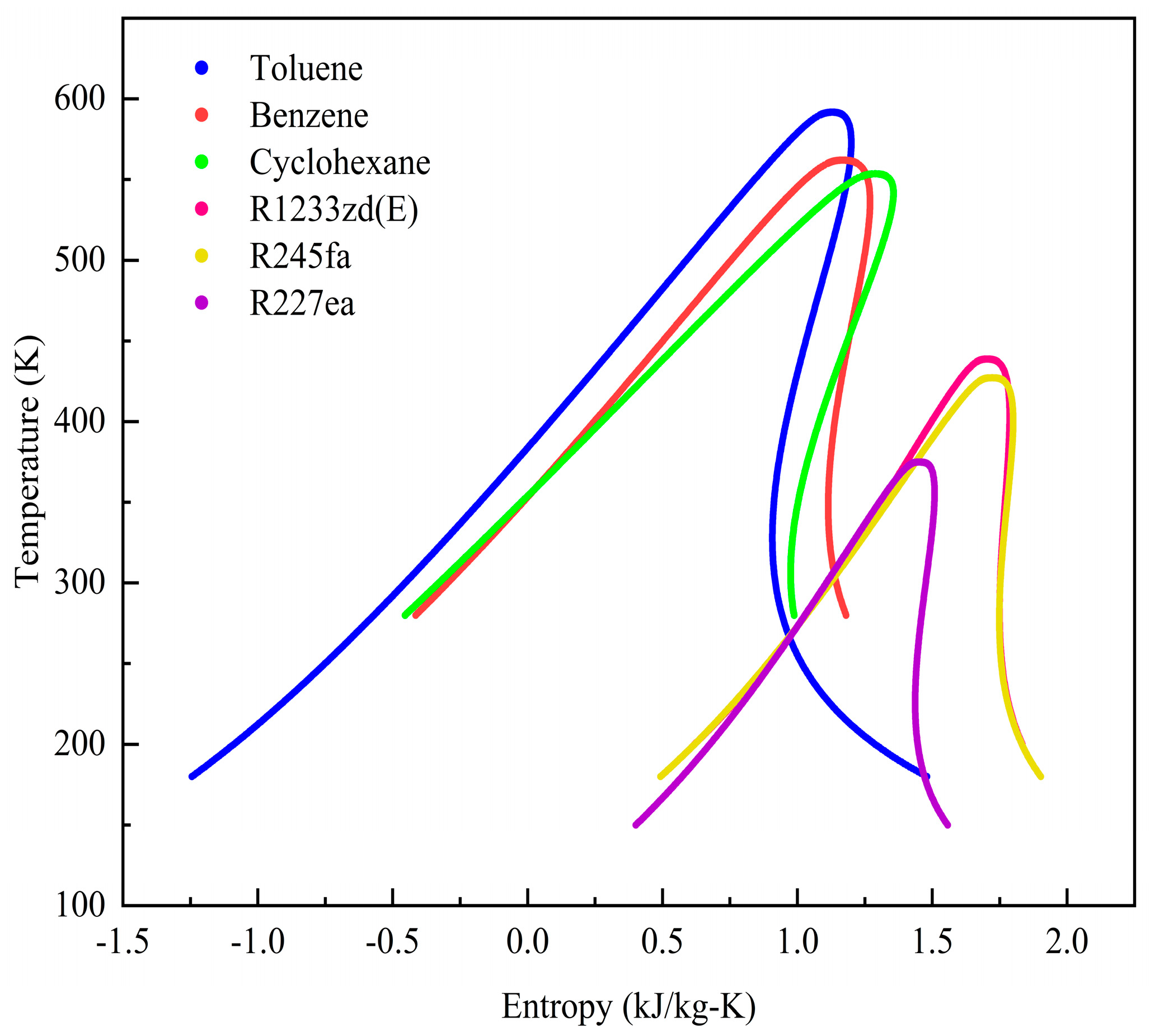
The selection of organics is an important step in designing a dual-loop ORC. Thermal, physical, environmental, and safety impacts should be considered when selecting working fluids. The ideal working fluid should have the following properties: high density; high specific heat; a critical temperature and pressure compatible with the heat source; low viscosity; low GWP and ODP; high heat of vaporization; additionally, it must be non-toxic and non-flammable. In addition, fluids with GWP values above 2500 were banned by the European Parliament regulation on fluorinated gases. CFC and HCFC fluids were prohibited by MARPOL Annex VI Regulation-12 [
22]. Based on the above requirements, the primary principles for selecting candidate fluids in this paper are: low GWP, zero ODP, and suitable critical temperature and pressure with the heat source. Toluene, benzene, and cyclohexane, which have low global warming potential (GWP), were selected for the HT loop since they have been proven in the literature [
23,
24,
25] to have superior performance in marine main engine EG waste heat recovery. R1233zd (E), R245fa, and R227ea were chosen for the LT loop based on their suitable critical temperatures and working pressures for low-temperature sources [
26,
27,
28]. R1233zd (E) has a low GWP value and is considered a replacement for R245fa [
29]. The T-s diagrams of the six working fluids are shown in
Figure 4. The properties of the working fluids are listed in
Table 2.
3. Thermal Model
The Organic Rankine Cycle (ORC) is a heat-to-power conversion technology, which is performed by expanders, heat exchangers, and pumps. In order to conduct a proper comparison, different powers must be analyzed [
30]. In this paper, mechanical and power generation losses were ignored. For the expander, the expansion is assumed to be adiabatic; therefore, the adiabatic power is equal to the mechanical as well as to the electrical power. For the pump, assuming that the fluid is incompressible, the hydraulic power is used as the ideal power, which is equal to the isentropic as well as the electrical power. Based on the combination of these powers, the isentropic efficiency can be defined as adiabatic power/isentropic power.
3.1. HT Loop System
The T-s diagram of the HT loop is shown in
Figure 5. The theoretical thermal process is composed of 1-2-3-4-5-6-1, which consists of the boiling (6–1), expansion (1–2), condensation (2–4), pumping (4–5), and preheating (5–6) processes.
Point 6 identifies the starting point for the boiling of the working fluid. Points 2’ and 5’ show the actual thermal process state points. Points 7–9 indicate an EG heat transfer process under constant pressure. The pinch point occurs at point 8. When the cooling fluid flows into the condenser, there are two situations: boiling (a) and unboiling (b).
The heat transferred by the EG can be calculated according to Equation (1):
The evaporator is divided into the preheating and boiling areas. The boiling process (point6→1 in
Figure 5) can be described as follows:
The heat released by the EG during phases 7–8 can be calculated as follows:
where Subscript
is the pinch point temperature.
The expansion process (1–2) can be described as follows:
The condensation process (2–4) can be described as follows:
The pumping process (4–5) can be described as follows:
The preheating process (5–6) can be described as follows:
The net power of the HT loop can be calculated as follows:
The thermal efficiency of the HT loop can be calculated as follows:
The back work ratio (BWR) of the HT loop refers to the ratio of pump work required and expander work.
3.2. LT Loop System
The T-s diagram of the LT loop is shown in
Figure 6. Nevertheless, there are two waste heat sources in the LT loop system.
The heat released by the JCW can be calculated as follows:
where subscript
is the jacket cooling water.
The evaporation process (5-1) can be described as follows:
According to the first law of thermodynamics:
The expansion process (1–2) can be described as follows:
The condensation process (2–4) can be described as follows:
The pumping process (4–5) can be described as follows:
The net power and thermal efficiency of the LT loop can be calculated as follows:
3.3. Dual-Loop System
The total net power and thermal efficiency of the system can be calculated as follows:
4. Materials and Methods
According to the critical temperature range of the working fluids, Toluene, Benzene, and Cyclohexane were selected as the working fluids for the HT loop. R227ea, R245fa, and R1233zd (E) were chosen as the working fluids for the LT loop. Nine combinations, such as Toluene-R227ea, Toluene-R245fa, Toluene-R1233zd (E), Cyclohexane-R227ea, Cyclohexane-R245fa, Cyclohexane-R1233zd (E), Benzene-R227ea, Benzene-R245fa, and Benzene-R1233zd (E), were built. The simulation was built in the SIMULINK and REFPROP 9.0 software environment.
Before the simulation, several assumptions were made, as follows:
- (1)
The EG outlet temperature was above 375 K.
- (2)
The heat exchanger pinch points were set at a temperature difference of 6 K [
31] or more.
- (3)
The isentropic efficiency was 0.8 for the expander and the pump.
- (4)
The condensation pressure in the HT Loop was 102 kPa to avoid sealing difficulties.
- (5)
The resistance loss of the pipeline and all kinds of heat transfer loss were ignored.
- (6)
A condensation temperature of 308.15 K was set in the LT loop.
As mentioned above, when the cooling fluid flows into the HT loop condenser, there are two cases: boiling (a), in which the pinch point occurs in the LT loop evaporator 2; unboiling (b), in which the pinch point happens in the LT loop evaporator 3. The T-s diagram of the LT loop in case a is shown in
Figure 7.
In the case of a, the
and
need to be set first. The LT loop working fluid heat absorption process can be divided into two stages: the preheating and boiling areas. The energy balance equations for the preheating and boiling areas can be obtained as follows:
Define:
where
is the ratio of the heat released by the heat source in the boiling area to the preheating area.
is the ratio of the heat absorbed by the working fluid of the LT loop in the boiling area to the preheating area. If
is greater than
, the evaporation pressure should be increased further. The opposite is true. The calculation processes should end up with an equal ratio between them.
The calculation process for the evaporation pressure of the LT loop in case a is listed in
Figure 8.
The
T-s diagram of the LT loop in case b is shown in
Figure 9. In the case of b, the
and
need to be set first. The heat absorption process of the LT loop can be classified as two evaporators: evaporator 2 and evaporator 3. The energy balance equation within evaporator 2 and evaporator 3 can be obtained as follows:
where
is the entropy of the working fluid at the outlet of the evaporator 2.
Define:
where
is the ratio of the condensation heat of the HT loop to the heat of the JCW.
is the ratio of the heat absorbed in evaporator 3 (HT loop condenser) to the evaporator 2. If
is greater than
, the evaporation pressure should be increased further. The opposite is true. The calculation processes should end up with an equal ratio between them.
The calculation flow for
in case b is listed in
Figure 10.
The optimum thermal parameters for a dual-loop ORC system can be found through the above calculation processes.
5. Results and Discussion
5.1. HT Loop
Toluene, benzene, and cyclohexane were selected as the working fluids for the HT loop. Because the condensation pressure in the HT loop was 102 kPa, the first set of analyses examined the impact of the ratio between evaporation pressure and critical pressure (RECP) on the thermal performance of the HT loop.
Figure 11a provides the variation of the EG outlet temperature with the RECP of the HT loop. There is a clear increasing trend between the EG outlet temperature and RECP. For cyclohexane, however, it decreases first and then increases. When the RECP of the HT loop is 0.072 (toluene), 0.061 (benzene), or 0.073 (cyclohexane), the EG outlet temperature was 393.6 K (toluene), 360.4 K (benzene), or 351.5 K (cyclohexane). Meanwhile, at an RECP of 0.605 (toluene), 0.509 (benzene), or 0.612 (cyclohexane) in the HT loop, the EG outlet temperature was 515.4 K (toluene), 422.5 K (benzene), or 393.9 K (cyclohexane). Considering the acid dew point (375 K), one interesting finding is that it would clearly be possible to meet the EG outlet temperature limit for toluene. At the same time, a higher evaporation pressure would be required for cyclohexane and benzene.
From
Figure 11b above, we can see that the heat of condensation for cyclohexane was reported to be significantly higher than that of the other two working fluids. With an RECP of 0.072 (toluene), 0.061 (benzene), or 0.073 (cyclohexane) in the HT loop, the heat of condensation was 1337.8 kW (toluene), 1574 kW (benzene), or 1639.9 kW (cyclohexane). Furthermore, at an RECP of 0.605 (toluene), 0.509 (benzene), or 0.612 (cyclohexane) in the HT loop, the heat of condensation was 409.9 kW (toluene), 996.9 kW (benzene), and 1202.2 or (Cyclohexane). What is striking about the data in this figure is that the condensation heat is a significant heat source in the LT loop. At a condensation pressure of 102 kPa, a lower evaporation pressure is required to produce as much condensation heat as possible. Compared to
Figure 11a, the most crucial relevant finding is that there will be an optimum evaporation pressure of the HT loop that both allows the EG outlet temperature limit to be met, and produces a higher amount of condensation heat.
Figure 11c shows the variation of the back work ratio as the RECP increases. The back work ratio at an RECP of 0.072 (toluene), 0.061 (benzene), or 0.073 (cyclohexane) in the HT loop was 1.04% (toluene), 0.92% (benzene), or 1.11% (cyclohexane). Additionally, at an RECP of 0.605 (toluene), 0.509 (benzene), or 0.612 (cyclohexane) in the HT loop, the back work ratio was 3.88% (toluene), 3.43% (benzene), and 4.02% (cyclohexane). The most interesting aspect of this figure is the trend of rapid growth in the back work ratio with increasing RECP. During isentropic compression, the pump discharge pressure rises in parallel with the increase in evaporation pressure, while the thermal parameters of the pump inlet remain constant. Cyclohexane has the highest back work ratio at the same RECP.
Figure 11d presents the trend in the net power increasing and decreasing with RECP. At an RECP of 0.072 (toluene), 0.061 (benzene), or 0.073 (cyclohexane) in the HT loop, the net power was 103.8 kW (toluene), 126.3 kW (benzene), or 130.4 kW (cyclohexane). Meanwhile, at an RECP of 0.605 (toluene), 0.509 (benzene), or 0.612 (cyclohexane) in the HT loop, the net power was 83 kW (toluene), 225.7 kW (benzene), and 245.7 kW (cyclohexane). Further analysis showed that the maximum net power in the HT loop with toluene as the working fluid was 160.3 kW at an RECP of 0.242. Similarly, when using Benzene as the working fluid in the HT loop, the maximum net power was 238 kW at an RECP of 0.336. Furthermore, in the HT loop, with cyclohexane as the working fluid, the maximum net power was 253.4 kW at an RECP of 0.428. This result may be explained by the fact that, due to the increase in the evaporation pressure, the power in the expander increases while the mass flow rate decreases. Therefore, an optimal evaporation pressure can be obtained. At the same evaporation pressure, cyclohexane has the highest net power of 253.4kW, followed by benzene and toluene.
The results obtained from the preliminary analysis of thermal efficiency are set out in
Figure 11e. When at an RECP of 0.605 (toluene), 0.509 (benzene), or 0.612 (cyclohexane) in the HT loop, the thermal efficiency is 16.9% (toluene), 18.5% (benzene), or 17% (cyclohexane). These relationships may partly be explained by the fact that the heat of the EG does not change much with increasing RECP, while the net power rises and the pump power increases less markedly. Furthermore, the growth of the thermal efficiency slows down as the RECP increases. Benzene has the highest thermal efficiency at the same RECP, followed by cyclohexane and toluene.
5.2. LT Loop and Dual Loop
R227ea, R245fa, and R1233zd (E) were selected as the working fluids for the LT loop. The condenser of the HT loop is the connection point for the dual loop. When the working fluid of the LT loop flows into the HT loop condenser, there are two cases: unboiling (a), and boiling (b). However, the heat exchange process must satisfy two requirements: (1) the evaporation temperature of the LT loop must not exceed the temperature difference limit; (2) the condenser of the HT loop must provide sufficient heat for the working fluid of the LT loop to complete the heat exchange process. The performances of the LT loop and the dual loop are discussed separately when cyclohexane, benzene and toluene are used in the HT loop.
5.2.1. Cyclohexane as the HT Loop’s Working Fluid; R227ea, R245fa, or R1233zd (E) as the LT Loop’s Working Fluid
Figure 12 compares the net power of LT loop with cyclohexane as the HT loop’s working fluid. It is interesting to note that, when the working fluid of the LT loop flows into the HT loop condenser, it is boiling, and the pinch point occurs in the LT loop evaporator 2. When the condensation heat load of the HT loop is 1574.4 kW, the maximum net power of the LT loop is 169.5 kW (R227ea), 175 kW (R245fa), or 176.6 kW (R1233zd (E)). This result may be explained by the fact that, when cyclohexane is used as the working fluid in the HT loop, the condensation pressure and temperature in the HT loop are 102 kPa and 354 K, respectively. On the other hand, the inlet temperature of the JCW is 363.15 K. As such, the evaporation temperature of the LT loop must be limited to below 348 K. The heat of condensation in the HT loop is another key factor that has an impact on the performance of the LT loop. Because the condensation heat of the HT loop drops along with the increase in the evaporation pressure in the HT loop, there is a reduction in the total heat in the LT loop.
Figure 13 provides the total net power data for the dual loop. With the increase in condensation heat load in the HT loop, the total net power tends to increase and decrease, and there is an optimum value. The simulation results show that, when the evaporation pressure of the HT loop is above 1800 kPa, the EG outlet temperature will be above the acid dew point of 375 K. Further analysis showed that, when the evaporation pressure of the HT loop is above 1800 kPa, and the condensation heat load is above 1388.2 kW, the total net power shows a decreasing trend. The maximum net power of the dual-loop system is 410.6 kW at an HT evaporation pressure of 1800 kPa and an LT evaporation pressure of 580 kPa. With the combination of cyclohexane-R1233zd (E), the total net power of the dual-loop ORC system could reach 410.6 kW.
5.2.2. Benzene as the HT Loop’s Working Fluid, R227ea, R245fa, R1233zd (E) as the LT Loop’s Working Fluid
As can be seen from
Figure 14, the net power of LT loop with R1233zd (E) as the LT loop working fluid was shown to be significantly higher than when the other two working fluids were used. However, the current study found that, when the cooling fluid flows into the HT loop condenser, it is boiling, and the pinch point occurs in the LT loop evaporator 2. A possible explanation for this might be that the thermal parameters of the condenser of the HT loop have a strong influence on system performance. First, the condenser temperature of HT loop (Benzene) is 353.4 K, which means that the evaporation temperature of the working fluid in the LT loop could not exceed 347.4 K. Second, the inlet temperature of the JCW is 363.15 K, which provides the necessary requirements for boiling in evaporator 2 of the LT loop. Third, the heat of condensation in the HT loop is not enough for the working fluid in the LT loop to start the boiling process. When the heat of condensation in the HT loop is 1459.2 kW, the maximum net power of the LT loop is 158.2 kW (R227ea), 163.5 kW (R245fa), or 165.1 kW (R1233zd (E)). With the decrease in the HT loop condensation heat, the net power of the LT loop showed an increasing trend. The net power of R1233zd (E) is always higher than that of both R245fa and R227ea.
Figure 15 illustrates the trend in the total net power of the dual loop. When the condensation heat of the HT loop is 1268 kW, the maximum total net power is 378.5 kW (R227ea), 383 kW (R245fa), or 384.5 kW (R1233zd (E)). Considering the EG temperature limit (375 K), it was discovered from the simulation that the condensation heat of the HT loop must be less than 1370 kW. The maximum total net power is 384.5 kW with the combination of Benzene-R1233zd (E).
5.2.3. Toluene as the HT Loop’s Working Fluid; R227ea, R245fa, or R1233zd (E) as the LT Loop’s Working Fluid
Figure 16 explains the decay trend in the net power of the LT loop with toluene as the HT loop’s working fluid. The pinch point of R227ea and R1233zd (E) is located in the LT loop evaporator 2. It is surprising that the pinch point of R245fa is located in the HT loop condenser when the condensation heat of the HT loop is 1337–1287.5 kW. At 1287.5–715.2 kW, the pinch point is located in the LT loop evaporator 2. Another possible explanation is that a higher evaporation pressure for the working fluid could be selected. When the toluene condensation temperature is 383.9 K, the maximum evaporation temperature is 376.9 K. When the heat of the JCW is certain, the HT loop condensation heat is sufficient to provide enough heat for the LT loop working fluid to start the boiling process, and the pinch point can be located in the HT loop condenser. On the contrary, if the HT loop condenser cannot provide sufficient heat for the LT loop to start the boiling process, the pinch point only occurs in the LT loop evaporator2.
Figure 17 shows the trend in the total net power of the dual loop. The net power of the dual loop tends to increase and decrease, and an optimum value exists. In the combination, R227ea is the largest and R1233zd (E) is the smallest.
According to these data, we can infer that higher condensation temperatures and levels of condensation heat of the HT loop are beneficial to the net power of the LT loop, but not to the HT loop. Due to the limitations of the exhaust gas outlet temperature, higher condensation temperatures and heat levels are unavailable.
Table 3 shows the optimal numerical setup for a dual-loop ORC.
6. Conclusions
A dual-loop ORC system was designed for recovering waste heat from a WARTSILA 5RT-flex35 marine main engine. The high-grade waste heat (EG) was recovered by the HT loop, and the low-grade waste heat (JCW and condensation heat) was recovered by the LT loop. The energy conversion of the marine main engine was measured at an 86% load. According to the critical temperature range of the working fluids, six working fluids, such as toluene, cyclohexane, benzene R1233zd (E), R245fa, and R227ea, were selected. The thermodynamic model of the dual-loop ORC system was established, and a simulation analysis of the performance of the system was carried out. The main conclusions obtained from this study are listed as follows:
In the HT loop, the maximum net power of the HT loop can reach 253.4kW with cyclohexane as the working fluid, and the maximum thermal efficiency of the HT loop can reach 18.5% with benzene as working fluid. It would clearly be possible to meet the EG outlet temperature limit for toluene at evaporation pressures of 300–2500 kPa. In addition, at a condensation pressure of 102 kPa, higher condensation temperatures and levels of condensation heat in the HT loop have a positive effect on the performance of the LT loop. Due to the EG outlet temperature limitation, higher condensation temperatures and heat levels are unavailable.
In the LT loop, the thermal states of the LT loop working fluid flowing into the HT loop condenser were analyzed in two cases, using the pinch point method. When the HT loop working fluid is either cyclohexane or benzene, the pinch points of R227ea, R1233zd (E), and R245fa are located in LT loop evaporator 2. However, with toluene as the HT loop working fluid, the pinch point of R245fa is located in the HT loop condenser at evaporation pressures of 300–500 kPa and in the LT loop evaporator 2 at evaporation pressures of 500–1800 kPa. Notably, the findings reported here shed new light on the fact that, in most conditions, the HT loop condensation heat could not provide enough heat for the LT loop’s working fluid to start the boiling process.
With the combination of cyclohexane-R1233zd (E), the total net power of the dual-loop ORC for marine main engines could reach 410.6 kW, which would improve the thermal efficiency of the marine main engine by 10.9%, when comparing the simulation results of the nine working fluid combinations.
Although the current study was based on a 4350KW diesel engine, the results show the great potential and value of a dual-loop organic Rankine cycle for waste heat recovery. It is strongly recommended that further techno-economic studies are carried out to investigate and experiment with dual-loop organic Rankine cycle technology.
Author Contributions
Conceptualization, J.Z.; methodology, A.K.; software, L.L. and S.X.; validation, S.X.; formal analysis, L.L. and A.K.; investigation, Y.Z.; resources, W.C.; data curation, L.L.; writing—original draft preparation, L.L.; writing—review and editing, W.C.; visualization, J.Z.; supervision, S.X.; project administration, A.K.; funding acquisition, L.L. and W.C. All authors have read and agreed to the published version of the manuscript.
Funding
The work was supported by the Science and Technology Plan Project of Fujian Province, China (grant numbers: 2022J011110) and the Thousand Sail Talent Program (2020–2023) of Jiang Su Maritime Institute, China.
Data Availability Statement
The datasets supporting the conclusions of this article are included within the article, and the sequencing data correspond with the Figures. The data will be made available upon reasonable academic request to the corresponding author, within the limitations of informed consent.
Acknowledgments
The authors would also like to thank the Wärtsilä Groups Co., Ltd. for supplying the materials.
Conflicts of Interest
The authors declare no conflict of interest.
Nomenclature
| Acronyms |
| ORC | organic Rankine cycle |
| M/E | marine main engine |
| EG | exhaust gas |
| JCW | jacket cooling water |
| HT | high temperature |
| LT | low temperature |
| GWP | global warming potential |
| ODP | ozone depletion potential |
| RECP | ratio between evaporation pressure and critical pressure |
| Subscripts |
| gas | exhaust gas |
| jw | jacket cooling water |
| PPT | pinch point temperature |
| boil | boiling process |
| wf | working fluid |
| exp | expander |
| pump | pump |
| con | condenser |
| pre | preheating process |
| net | net |
| the | thermal |
| eva | evaporation process |
| tot | total |
| Nomenclature |
| Q | heat load(kW) |
| ṁ | mass flow rate (kg/s) |
| h | specific enthalpy (kJ/kg) |
| cp | specific heat capacity (kJ/(kg K)) |
| T | temperature (K) |
| W | power (kW) |
| P | pressure (kPa) |
| Greek symbols |
| η | efficiency |
References
- Shu, G.; Liang, Y.; Wei, H.; Tian, H.; Zhao, J.; Liu, L. A review of waste heat recovery on two-stroke IC engine aboard ships. Renew. Sustain. Energy Rev. 2013, 19, 385–401. [Google Scholar] [CrossRef]
- Xing, H.; Spence, S.; Chen, H. A comprehensive review on countermeasures for CO2 emissions from ships. Renew. Sustain. Energy Rev. 2020, 134, 110222. [Google Scholar] [CrossRef]
- Mahmoudi, A.; Fazli, M.; Morad, M.R. A recent review of waste heat recovery by Organic Rankine Cycle. Appl. Therm. Eng. 2018, 143, 660–675. [Google Scholar] [CrossRef]
- Tchanche, B.F.; Lambrinos, G.; Frangoudakis, A.; Papadakis, G. Low-grade heat conversion into power using organic Rankine cycles—A review of various applications. Renew. Sustain. Energy Rev. 2011, 15, 3963–3979. [Google Scholar] [CrossRef]
- Quoilin, S.; Broek, M.V.D.; Declaye, S.; Dewallef, P.; Lemort, V. Techno-economic survey of Organic Rankine Cycle (ORC) systems. Renew. Sustain. Energy Rev. 2013, 22, 168–186. [Google Scholar] [CrossRef] [Green Version]
- Singh, D.V.; Pedersen, E. A review of waste heat recovery technologies for maritime applications. Energy Convers. Manag. 2016, 111, 315–328. [Google Scholar] [CrossRef]
- Ma, J.; Liu, L.; Zhu, T.; Zhang, T. Cascade utilization of exhaust gas and jacket water waste heat from an Internal Combustion Engine by a single loop Organic Rankine Cycle system. Appl. Therm. Eng. 2016, 107, 218–226. [Google Scholar] [CrossRef]
- Yang, M.-H. Optimizations of the waste heat recovery system for a large marine diesel engine based on transcritical Rankine cycle. Energy 2016, 113, 1109–1124. [Google Scholar] [CrossRef]
- Yang, M.-H.; Yeh, R.-H. Analyzing the optimization of an organic Rankine cycle system for recovering waste heat from a large marine engine containing a cooling water system. Energy Convers. Manag. 2014, 88, 999–1010. [Google Scholar] [CrossRef]
- Yang, M.-H.; Yeh, R.-H. Thermodynamic and economic performances optimization of an organic Rankine cycle system utilizing exhaust gas of a large marine diesel engine. Appl. Energy 2015, 149, 1–12. [Google Scholar] [CrossRef]
- Ge, Z.; Li, J.; Duan, Y.; Yang, Z.; Xie, Z. Thermodynamic Performance Analyses and Optimization of Dual-Loop Organic Rankine Cycles for Internal Combustion Engine Waste Heat Recovery. Appl. Sci. 2019, 9, 680. [Google Scholar] [CrossRef] [Green Version]
- Zhang, H.G.; Wang, E.H.; Fan, B.Y. A performance analysis of a novel system of a dual loop bottoming organic Rankine cycle (ORC) with a light-duty diesel engine. Appl. Energy 2013, 102, 1504–1513. [Google Scholar] [CrossRef]
- Yang, F.; Cho, H.; Zhang, H.; Zhang, J. Thermoeconomic multi-objective optimization of a dual loop organic Rankine cycle (ORC) for CNG engine waste heat recovery. Appl. Energy 2017, 205, 1100–1118. [Google Scholar] [CrossRef]
- Abbas, W.K.A.; Vrabec, J. Cascaded dual-loop organic Rankine cycle with alkanes and low global warming potential refrigerants as working fluids. Energy Convers. Manag. 2021, 249, 114843. [Google Scholar] [CrossRef]
- Ping, X.; Yao, B.; Zhang, H.; Yang, F. Thermodynamic analysis and high-dimensional evolutionary many-objective optimization of dual loop organic Rankine cycle (DORC) for CNG engine waste heat recovery. Energy 2021, 236, 121508. [Google Scholar] [CrossRef]
- Wang, Z.; Hu, Y.; Xia, X.; Zuo, Q.; Zhao, B.; Li, Z. Thermo-economic selection criteria of working fluid used in dual-loop ORC for engine waste heat recovery by multi-objective optimization. Energy 2020, 197, 117053. [Google Scholar] [CrossRef]
- Zhi, L.-H.; Hu, P.; Chen, L.-X.; Zhao, G. Parametric analysis and optimization of transcritical-subcritical dual-loop organic Rankine cycle using zeotropic mixtures for engine waste heat recovery. Energy Convers. Manag. 2019, 195, 770–787. [Google Scholar] [CrossRef]
- Shu, G.; Yu, Z.; Liu, P.; Xu, Z.; Sun, R. Potential of a thermofluidic feed pump on performance improvement of the dual-loop Rankine cycle using for engine waste heat recovery. Energy Convers. Manag. 2018, 171, 1150–1162. [Google Scholar] [CrossRef]
- Sciubba, E.; Tocci, L.; Toro, C. Thermodynamic analysis of a Rankine dual loop waste thermal energy recovery system. Energy Convers. Manag. 2016, 122, 109–118. [Google Scholar] [CrossRef]
- Ge, Z.; Li, J.; Liu, Q.; Duan, Y.; Yang, Z. Thermodynamic analysis of dual-loop organic Rankine cycle using zeotropic mixtures for internal combustion engine waste heat recovery. Energy Convers. Manag. 2018, 166, 201–214. [Google Scholar] [CrossRef]
- Bahadori, A. Estimation of combustion flue gas acid dew point during heat recovery and efficiency gain. Appl. Therm. Eng. 2011, 31, 1457–1462. [Google Scholar] [CrossRef]
- Civgin, M.G.; Deniz, C. Analyzing the dual-loop organic rankine cycle for waste heat recovery of container vessel. Appl. Therm. Eng. 2021, 199, 117512. [Google Scholar] [CrossRef]
- Wang, E.; Zhang, M.; Meng, F.; Zhang, H. Zeotropic working fluid selection for an organic Rankine cycle bottoming with a marine engine. Energy 2022, 243, 123097. [Google Scholar] [CrossRef]
- Siddiqi, M.A.; Atakan, B. Alkanes as fluids in Rankine cycles in comparison to water, benzene and toluene. Energy 2012, 45, 256–263. [Google Scholar] [CrossRef]
- Bellos, E.; Tzivanidis, C. Investigation of a hybrid ORC driven by waste heat and solar energy. Energy Convers. Manag. 2018, 156, 427–439. [Google Scholar] [CrossRef]
- Yang, J.; Sun, Z.; Yu, B.; Chen, J. Experimental comparison and optimization guidance of R1233zd(E) as a drop-in replacement to R245fa for organic Rankine cycle application. Appl. Therm. Eng. 2018, 141, 10–19. [Google Scholar] [CrossRef]
- Borsukiewicz-Gozdur, A. Experimental investigation of R227ea applied as working fluid in the ORC power plant with hermetic turbogenerator. Appl. Therm. Eng. 2013, 56, 126–133. [Google Scholar] [CrossRef]
- Karellas, S.; Schuster, A.; Leontaritis, A.-D. Influence of supercritical ORC parameters on plate heat exchanger design. Appl. Therm. Eng. 2012, 33–34, 70–76. [Google Scholar] [CrossRef]
- Eyerer, S.; Wieland, C.; Vandersickel, A.; Spliethoff, H. Experimental study of an ORC (Organic Rankine Cycle) and analysis of R1233zd-E as a drop-in replacement for R245fa for low temperature heat utilization. Energy 2016, 103, 660–671. [Google Scholar] [CrossRef]
- Landelle, A.; Tauveron, N.; Haberschill, P.; Revellin, R.; Colasson, S. Performance Evaluation and Comparison of Experimental Organic Rankine Cycle Prototypes from Published Data. Energy Procedia 2017, 105, 1706–1711. [Google Scholar] [CrossRef]
- Zhang, C.; Liu, C.; Wang, S.; Xu, X.; Li, Q. Thermo-economic comparison of subcritical organic Rankine cycle based on different heat exchanger configurations. Energy 2017, 123, 728–741. [Google Scholar] [CrossRef]
Figure 1.
Physical picture of Wartsilas5rt-flex35.
Figure 1.
Physical picture of Wartsilas5rt-flex35.
Figure 2.
The fuel energy conversion diagram.
Figure 2.
The fuel energy conversion diagram.
Figure 3.
Schematic diagram of a dual-loop ORC.
Figure 3.
Schematic diagram of a dual-loop ORC.
Figure 4.
T-s diagram of the working fluids.
Figure 4.
T-s diagram of the working fluids.
Figure 5.
T-s diagram of the HT loop.
Figure 5.
T-s diagram of the HT loop.
Figure 6.
T-s diagram of the LT loop.
Figure 6.
T-s diagram of the LT loop.
Figure 7.
T-s diagram of the LT loop in case a.
Figure 7.
T-s diagram of the LT loop in case a.
Figure 8.
Flow chart of the calculation in case a.
Figure 8.
Flow chart of the calculation in case a.
Figure 9.
T-s diagram of the LT loop in case b.
Figure 9.
T-s diagram of the LT loop in case b.
Figure 10.
Flow chart of the calculation in case b.
Figure 10.
Flow chart of the calculation in case b.
Figure 11.
Thermodynamic parameters of the HT-loop ORC system. (a) this is the variation of the EG outlet temperature with the RECP of the HT loop. (b) this is the variation of the heat of condensation with the RECP of the HT loop. (c) this is the variation of the back work ratio as the RECP increases. (d) this is the trend in the net power increasing and decreasing with RECP. (e) this is the variation of the thermal efficiency with the RECP of the HT loop.
Figure 12.
Net power of the LT loop with cyclohexane as the HT loop’s working fluid.
Figure 12.
Net power of the LT loop with cyclohexane as the HT loop’s working fluid.
Figure 13.
Total net power of the dual-loop system with cyclohexane as the HT loop working fluid.
Figure 13.
Total net power of the dual-loop system with cyclohexane as the HT loop working fluid.
Figure 14.
Net power of the LT loop with benzene as the HT loop’s working fluid.
Figure 14.
Net power of the LT loop with benzene as the HT loop’s working fluid.
Figure 15.
Total net power of the dual loop with benzene as the HT loop’s working fluid.
Figure 15.
Total net power of the dual loop with benzene as the HT loop’s working fluid.
Figure 16.
Net power of the LT loop with toluene as the HT loop’s working fluid.
Figure 16.
Net power of the LT loop with toluene as the HT loop’s working fluid.
Figure 17.
Total net power of the dual loop with toluene as the HT loop’s working fluid.
Figure 17.
Total net power of the dual loop with toluene as the HT loop’s working fluid.
Table 1.
The recorded operating parameters of WARTSILA 5RT-flex35.
Table 1.
The recorded operating parameters of WARTSILA 5RT-flex35.
| Category | Unit | Value |
|---|
| Maximum continuous power | kW | 4350 |
| Load | | 86.20% |
| Shaft output power | kW | 3750 |
| Numbers of cylinders | | 5 |
| Rotation speed per min (RPM) | r/min | 155 |
| The inlet temperature of the EG | K | 578.15 |
| The outlet temperature of the EG | K | 378.15 |
| The mass flow rate of the EG | kg/h | 26,766.79 |
| Average specific heat capacity of the EG | kJ/(kg K) | 1.05 |
| The inlet temperature of the JCW | K | 338.15 |
| The outlet temperature of the JCW | K | 363.15 |
| The mass flow rate of the JCW | kg/h | 19,760 |
| Average specific heat capacity of the JCW | kJ/(kg K) | 4.19 |
Table 2.
Properties of the working fluids.
Table 2.
Properties of the working fluids.
| Name | Chemical Formula | GWP | ODP | Normal Boiling Point (K) | Critical Pressure (kPa) |
|---|
| Toluene | C7H8 | 3 | 0 | 383.75 | 4126.30 |
| Benzene | C6H6 | ~20 | 0 | 353.22 | 4907.30 |
| Cyclohexane | C6H12 | ~20 | 0 | 353.87 | 4080.50 |
| R1233zd (E) | C3H2ClF3 | 7 | 0 | 291.47 | 3570.90 |
| R245fa | CF3CH2CHF2 | 1030 | 0 | 288.29 | 3651.00 |
| R227ea | CF3CHFCF3 | 3500 | 0 | 256.81 | 2925.00 |
Table 3.
The optimal numerical setup for a dual-loop ORC.
Table 3.
The optimal numerical setup for a dual-loop ORC.
| Dual-Loop ORC | HT Loop | LT Loop | HT Loop | LT Loop | HT Loop | LT Loop |
|---|
| Working fluid | Cyclohexane | R1233zd (E) | Benzene | R1233zd (E) | Toluene | R227ea |
| Peva (kPa) | 1800 | 580 | 1300 | 569 | 700 | 1850 |
| Pcon (kPa) | 102 | 182 | 102 | 182 | 102 | 608 |
| Mass flow (kg/s) | 2.76 | 8.99 | 2.82 | 8.68 | 2.72 | 14.2 |
| Tgas,out (K) | 375.3 | | 393.9 | | 410.7 | |
| Absorbed heat load (kW) | 1583 | 1913.1 | 1497.7 | 1843 | 1306.8 | 1730 |
| Net power (kW) | 253.4 | 157.2 | 234.8 | 149.6 | 154.4 | 186 |
| Max total net power (kW) | 410.6 | 384.4 | 340.4 |
| Thermal efficiency | 0.16 | 0.082 | 0.156 | 0.081 | 0.118 | 0.107 |
| Publisher’s Note: MDPI stays neutral with regard to jurisdictional claims in published maps and institutional affiliations. |
© 2022 by the authors. Licensee MDPI, Basel, Switzerland. This article is an open access article distributed under the terms and conditions of the Creative Commons Attribution (CC BY) license (https://creativecommons.org/licenses/by/4.0/).


