1. Introduction
Electric machines have been among the largest consumers of electricity for many years. They are used in many industries as key elements of many drive systems. It is also difficult to imagine everyday life without the possibility of using basic appliances with electric motors in households. The market of electric vehicles [
1] has been developing rapidly for several years now—not only passenger cars but also public transport vehicles (e.g., buses [
2]) and inland waterway boats [
3]. This development was possible owing to, among other things, the development of highly efficient electric motors, particularly synchronous motors with permanent magnets, which are characterized by a high power-to-weight ratio, a high efficiency and good dynamic parameters [
4]. Modern drive systems often operate at high rotational speeds, which means that the stator windings must be supplied with high-frequency voltage. In modern drive systems, in order to supply permanent magnet motors, power electronic converters are used, which enable the implementation of complex control strategies. The most frequently used converter systems are those based on PWM modulation, in which the regulation of output parameters (voltage, current and frequency) is performed by modulating the pulse width and changing the switching frequency of power electronic transistors. This control enables the smooth regulation of the frequency and amplitude of the first harmonic of the voltage supplying the electric machine. Undoubtedly, the advantages of using converters have led to their widespread use in electric drives. Unfortunately, these converters introduce higher harmonics into the voltage supplying the motor, which, in turn, triggers a number of unfavorable phenomena. The use of converters contributes to, among other things, an increase in the generated noise and an increase in the amplitudes of forces causing vibrations of the motor [
5], leading to a higher risk of bearing damage. Another negative result caused by converter usage is the appearance of bearing voltages and currents [
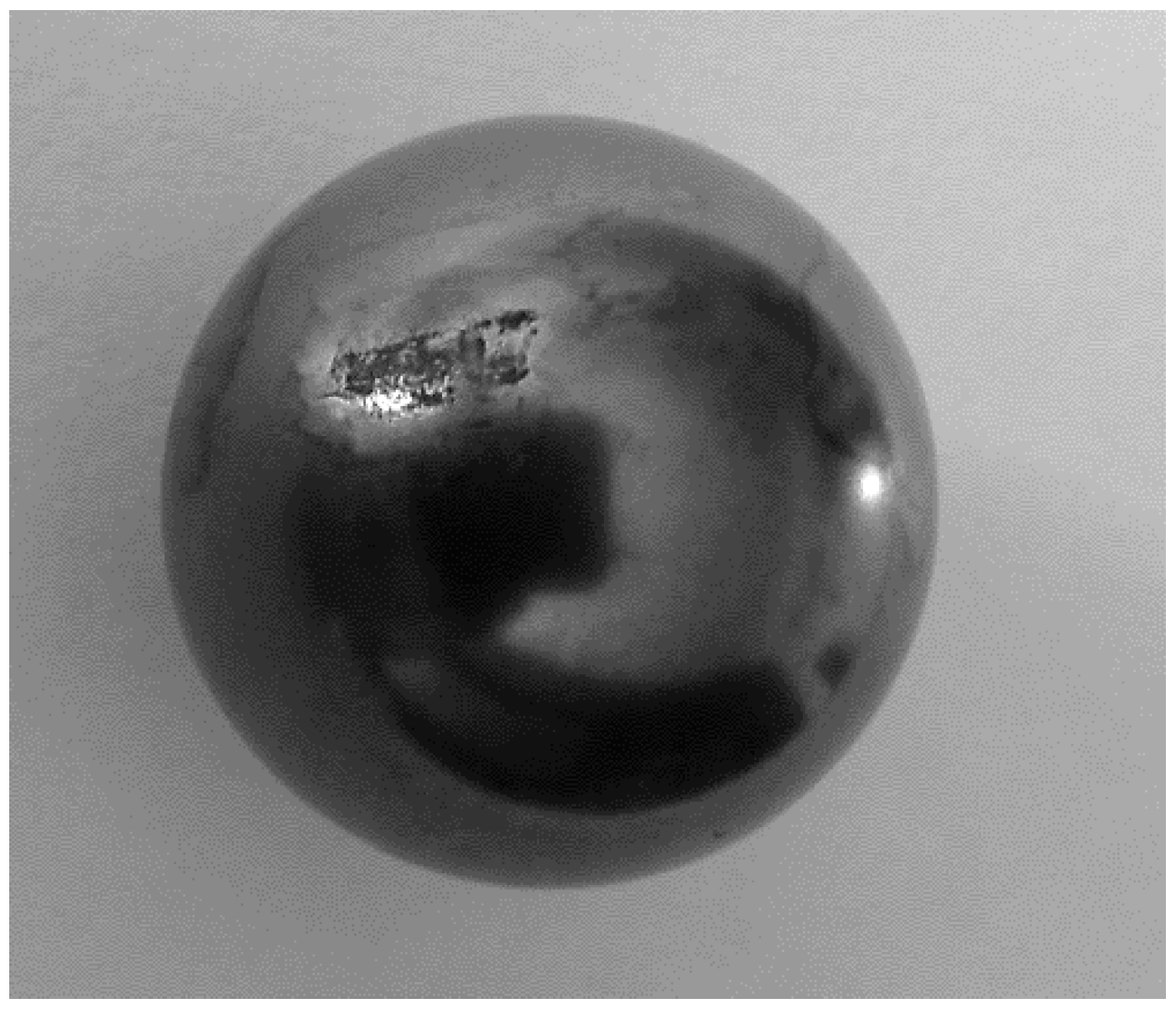
6]. There is a small layer of oil film between the raceways and rolling elements of the bearings. The bearing voltage can break the oil film, causing the current flow in the circuit consisting of the bearings, the frame and the machine shaft. Due to the small contact area between raceways and rolling elements, the current flow can reach densities that can damage the raceway surfaces. This current causes local pitting on the raceway surfaces and on the rolling elements of the bearings. An example of damage to the rolling element of a bearing resulting from the flow of the bearing current is shown in
Figure 1. The bearing voltage is the main source of bearing currents. On the contact surfaces, that is, where rolling elements touch the raceways, an effect similar to electrical arc welding occurs. The current flowing through the bearing often causes local heating of the bearing, even to the melting point. In places where the metal has been melted, traces of discoloration or pitting of various shapes and sizes are formed [
7]. The further flow of bearing currents in the presence of precipitated metal filings results in a deepening of the bearing damage process. The intensity of the damage largely depends on the intensity of the current, the time of its flow, the rotational speed, the mechanical load and the type of lubricant used [
8].
The available publications provide comprehensive information on bearing failures by categorizing the causes of their occurrence and present photographs of the consequences of bearing current flow [
7,
9,
10,
11]. Bearing current density
Jb is defined as the ratio of the bearing current amplitude
Ib(peak) to the Hertzian contact area
AHz (1):
The available literature provides different values of the permissible bearing current densities, but in general, it can be assumed that values below
Jb < 0.1 A/mm
2 do not threaten the bearing service life, while the bearing current with a density of
Jb > 1 A/mm
2 significantly reduces the failure-free time of its operation [
12]. For this reason, sliding bearings, which are used in high-power machines, are less sensitive to the phenomenon of bearing currents due to the much larger contact area between the bearing elements [
12].
It is worth emphasizing here that bearing currents may appear not only when motors are supplied from power electronic converters but also when the supply voltage is sinusoidal [
13]. The mechanisms for the generation of bearing currents are different for each case. When the machine is supplied with sinusoidal voltage, bearing currents are characterized by a low frequency (
f < 1 kHz) and occur in machines with asymmetry in the electromagnetic circuit [
14]. This asymmetry may be caused by, among other things, the asymmetry of the air gap (static or dynamic), damage to the magnets placed in the rotor, the asymmetrical connection of windings, the short-circuit of the stator sheets, the anisotropy of the magnetic circuit or the segmentation of the stator core, which occurs in large-sized electrical machines. Another reason for the formation of magnetic circuit asymmetry may be the asymmetrical arrangement of ventilation ducts or stator core mounting welds on the magnetic circuit. In such cases, a circular flux appears in the stator yoke, surrounding the machine shaft [
15]. It induces a potential difference between the ends of the shaft, under the influence of which current flows in a closed circuit consisting of the frame, bearings and shaft [
16]. For a symmetrical electromagnetic circuit of the machine, the distribution of the magnetic field across the cross-section is the same within each polar pitch, so circular flux does not occur.
In the case of machines powered by power electronic converters, the main role is played by the interaction of the fast-changing common-mode voltage occurring at the winding star point with the system of parasitic capacitances of the machine. In both cases, the bearing currents can cause severe damage to the raceways and rolling elements. The damage intensity depends mainly on the bearing current, its duration, its bearing load and its rotational speed. Therefore, methods of limiting bearing voltages in electrical machines are still being developed. Considering that the vast majority of permanent magnet synchronous machines work with power electronic converters, this article focuses on methods of limiting bearing voltages and currents under such power supply. More detailed information related to the discussed issues is described in the second chapter of this article.
The aim of the article is to present the idea of limiting bearing voltages in electric machines, particularly in synchronous machines with permanent magnets placed inside the rotor. The research presented in the article is a continuation of the publication [
17], in which the authors conducted a detailed analysis of the impact of machine design solutions on parasitic capacitances. It was limited to the simulation of two-dimensional models, and the subject of the research was the comparison of, among other things, the shape of the stator slot opening, the number of shielding wires used in the slot opening space and the demonstration of their influence on parasitic capacitances and bearing voltages. The conclusions were used to conduct research aimed at determining the internal capacitances of the machine on the basis of a three-dimensional model of an electric machine with an IPM rotor.
2. Bearing Voltages and Currents in Electric Machines Powered by Power Electronic Converters
The vast majority of currently used power electronic converters work with PWM (Pulse Width Modulation), for which the SVM (Space Vector Modulation) method is most frequently used. It consists in forming the output voltage of the converter using vector relationships. In the case of a two-level power electronic converter, the diagram of which is shown in
Figure 2a, each of the operating states of the system is represented by voltage vectors: six active vectors and two zero vectors. In the SVM algorithm, the vector of the set converter output voltage is generated for each transistor switching period as a combination of zero vectors and two adjacent active vectors. The transistor switching combinations corresponding to each control vector are shown in
Figure 2b.
The sequence and switching times of the individual transistors are controlled by a vector modulator in the control system. The examples of the output voltages of a two-level converter,
uu,
uv and
uw, are shown in
Figure 3. The voltages on the individual phases of the winding assume values that depend on the voltage in the DC-link circuit
UDC:
UDC/2 or −
UDC/2. The result of the voltages at the output of the converter formed in such a way is the presence of a non-zero voltage at the neutral point of the winding called the common-mode voltage
uCM, the value of which is equal to the average value of the voltages in the individual phases according to formula (2) [
18]:
The turn-on times of transistors depend on the amplitude of the voltage vector and the sector in which it is located. The construction of the voltage vector
Vref can be described by Equation (3) [
19]:
where:
V0—zero vector;
V1, V2—active vectors;
Ts—switching period of transistors (1/fs);
T0—duration of the zero vector;
T1, T2—durations of active vectors V1 and V2.
The common-mode voltage when the machine is fed from a two-level converter has the shape of a stepped curve, with a frequency equal to the switching frequency of the transistors and a steepness resulting from the switching rate. The
uCM voltage assumes values of −
UDC/2, −
UDC/6,
UDC/6 and
UDC/2, with amplitudes falling on zero vectors, as shown in
Figure 3.
As shown above, powering the motor from a power electronic converter contributes to the occurrence of a non-zero common-mode voltage
uCM in the stator winding. The presence of this voltage can contribute to capacitive or discharge-bearing current (EDM) [
15]. Capacitive current refers to the case where the bearing current
ib = (d
ub/d
t) ∙
Cb flows through the oil film of the bearing. Due to the small capacitance of the bearing
Cb, capacitive currents are usually harmless to the bearing. The second type of bearing current (EDM) occurs when the oil film is punctured, and it appears as a point short-circuit arc that destructively affects the bearing raceway surfaces. The main elements through which the bearing current flows are the metal structural parts of the machine. Since the resistances of the shaft, bearing and frame are very small, the oil film has a decisive influence on the value of the bearing current. Its thickness decreases with increasing temperature. If its electrical strength is exceeded, then a short-term current pulse flows through the bearing, which is the main cause of pitting on the bearing raceways and rolling elements. Both types of currents occur when there is a stepped, rapidly changing common-mode voltage in the machine winding that affects the parasitic capacitances of the machine.
2.1. Parasitic Capacitances of the Machine and Their Equivalent Diagram
As described above, the power supply of a machine from a power electronic converter involves the occurrence of common-mode voltage uCM, whose rapid changes duCM/dt reaching up to several kV/µs stimulate the capacitive couplings present in an electric machine and play an important role in the mechanism of generating bearing currents. These capacitances occur between three characteristic elements (frame, winding and rotor) isolated from each other. In order to analyze the equivalent circuit that takes into account the parasitic capacitances of the machine, it is necessary to distinguish its following design elements:
Stator iron core, placed in the grounded frame of the machine;
Stator winding, isolated from the inner surface of the stator slots and supplied from an external voltage source;
Rotor installed inside the frame by bearings, isolated from the structure due to the presence of an oil film.
Bearing in mind the insulation between the stator winding and the ferromagnetic circuit, as well as the isolation of the rotor from the other structural components of the machine (due to the presence of an oil film in the bearings), one can formulate its equivalent circuit diagram that consists of parasitic capacitances [
20]. In a simplified model of an electric machine, capacitances can be distinguished:
Cws—the capacitance between the stator winding and the grounded stator,
Cwr—the capacitance between the stator winding and the rotor,
Csr—the capacitance between the rotor and the grounded stator,
Cb1 and
Cb2—the capacitances of the bearings on the drive and non-drive sides [
21]. It is worth noting that the capacitance
Cwr occurs both along the active length of the stator iron core and in the end-windings region. Thus, it is possible to distinguish two components of
Cwr capacitance connected in parallel:
Cwr(ew) and
Cwr(slot), which correspond to the capacitance between the windings located in the stator slots and the end-winding capacitance, respectively [
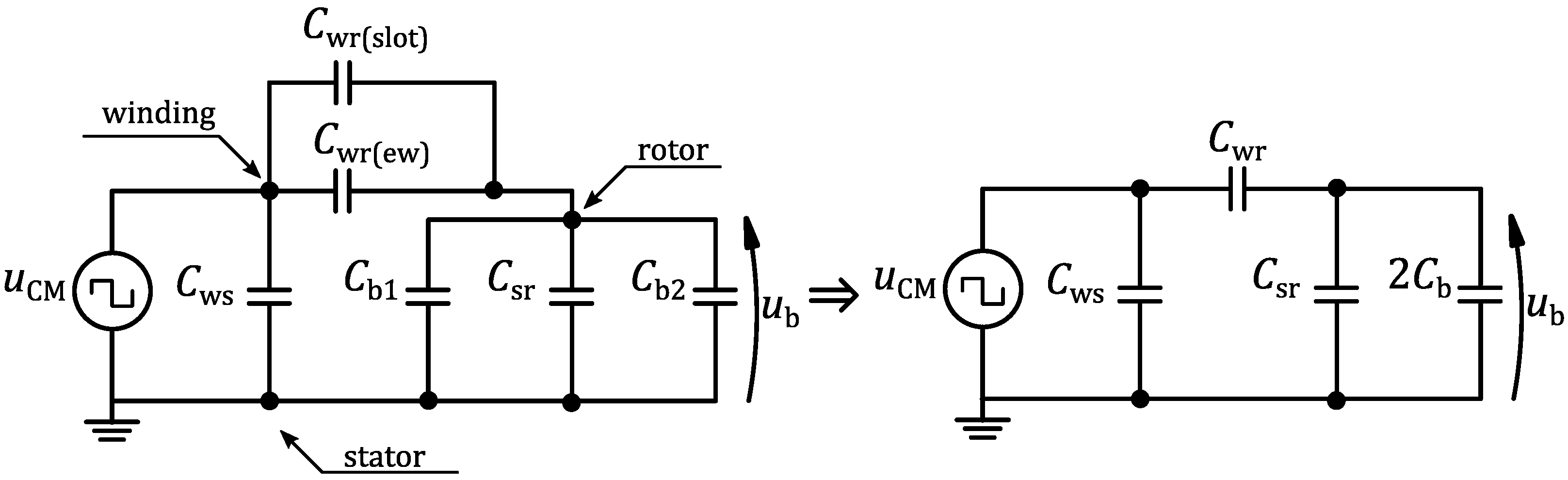
22]. The location of the above-mentioned parasitic capacitances is illustrated in a cross-sectional view of the electric machine in
Figure 4, whereas the equivalent diagram with lumped parameters is shown in
Figure 5. It is worth noting here that, in the case of supplying the stator windings with a sinusoidal voltage at the frequency of
f = 50 Hz, these capacitances do not play any role in generating bearing voltages due to the large value of reactance
Xc = 1/(2π
fC).
The value of the Cws capacitance depends on, among other things, the geometrical dimensions of the machine and the configuration of the windings, as well as on the dielectric parameters of the stator slot insulation used. The Cwr value depends on the shape and dimensions of the electromagnetic circuit. The article omits the bearing resistances, limiting it to the equivalent diagram that consists only of parasitic capacitances.
The equivalent circuit diagram shown in
Figure 5 explains that the source of the voltage
ub that occurs between the raceways of the bearing is the common-mode voltage
uCM. The ratio of these voltages (BVR—Bearing Voltage Ratio) is given by the equation [
23,
24]:
The above equation shows the relationship between the bearing voltage and the common-mode voltage, ignoring the stator-to-ground resistance. The higher the BVR coefficient, the greater the observed values of the bearing voltages, which are the main sources of currents flowing through the bearings. Various methods are used to limit the bearing voltages. They are described in the next chapter of the article.
3. Methods of Limiting Bearing Voltages
The dynamic development of electric machines and drives has contributed to the development of various methods of counteracting and reducing the effects of bearing current flow. Generally, two groups of methods can be distinguished:
The first group of methods includes methods based on modifications to the power supply systems of the electric machine (the use of multi-level converters, the modification of control algorithms [
25], the use of additional passive filters [
26] or active filters [
24,
27]) as well as modifications to the machine structure (the use of shielding windings, the use of an oblique opening of the stator slots [
28], etc.). The second group of methods is restricted to the use of insulated bearings—fully ceramic or hybrid [
29]. The use of appropriate countermeasures depends primarily on the type of supply and the applicability of individual methods. Both groups of methods can be combined and applied in drive systems in order to provide protection against the destructive phenomenon of bearing voltages and currents.
As was shown in the previous chapter, the value of the bearing voltage depends on the parasitic capacitances, particularly on the capacitance between the stator winding and the rotor. Different solutions aimed at limiting the
Cwr capacitance are presented in existing publications on the subject. One of them is to increase the distance between the stator windings located in the slots and the rotor surface [
30]. Solutions based on the introduction of a grounded shield into the slot opening space [
31,
32] and around the stator end-winding [
33,
34,
35] are highly effective. These shields are implemented in the form of, among other things, tapes of conductive material or copper wires.
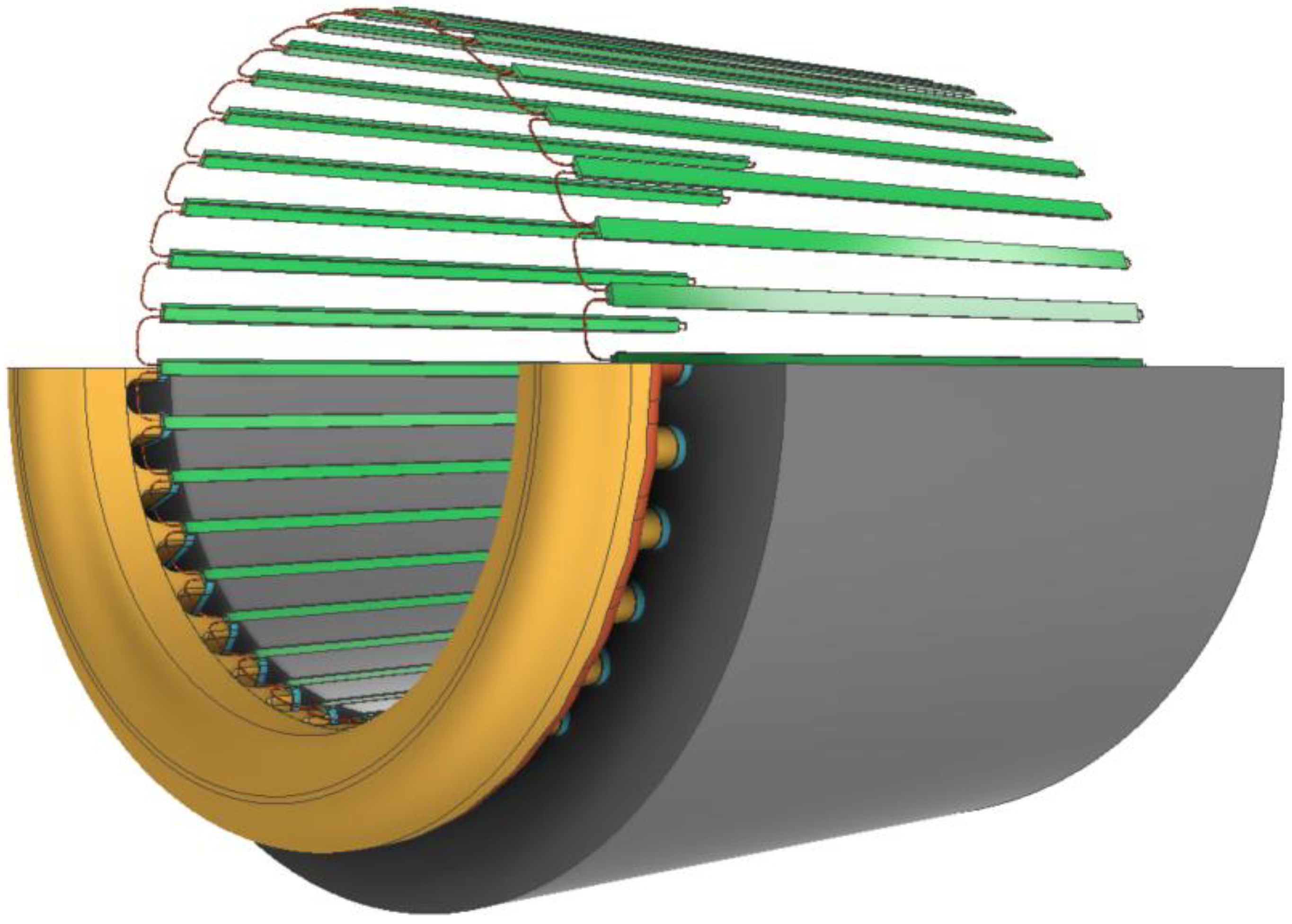
The concept suggested by the authors is based on the use of special wedges closing the stator slots, in which there are copper wires along the entire length. These wires can be connected, for example, in series, thus creating a special shielding winding, one terminal of which is connected to the grounded frame. Such a solution is characterized, among other things, by the following advantages: the wires are evenly distributed in the wedges along the entire slot opening length of the stator core and are also prevented from accidentally touching the stator winding. The concept and an exemplary connection of the wires in the slot wedges are shown in
Figure 6 and
Figure 7.
4. Analysis of the Influence of Shielding Windings on the Parasitic Capacitances of a Permanent Magnet Synchronous Machine
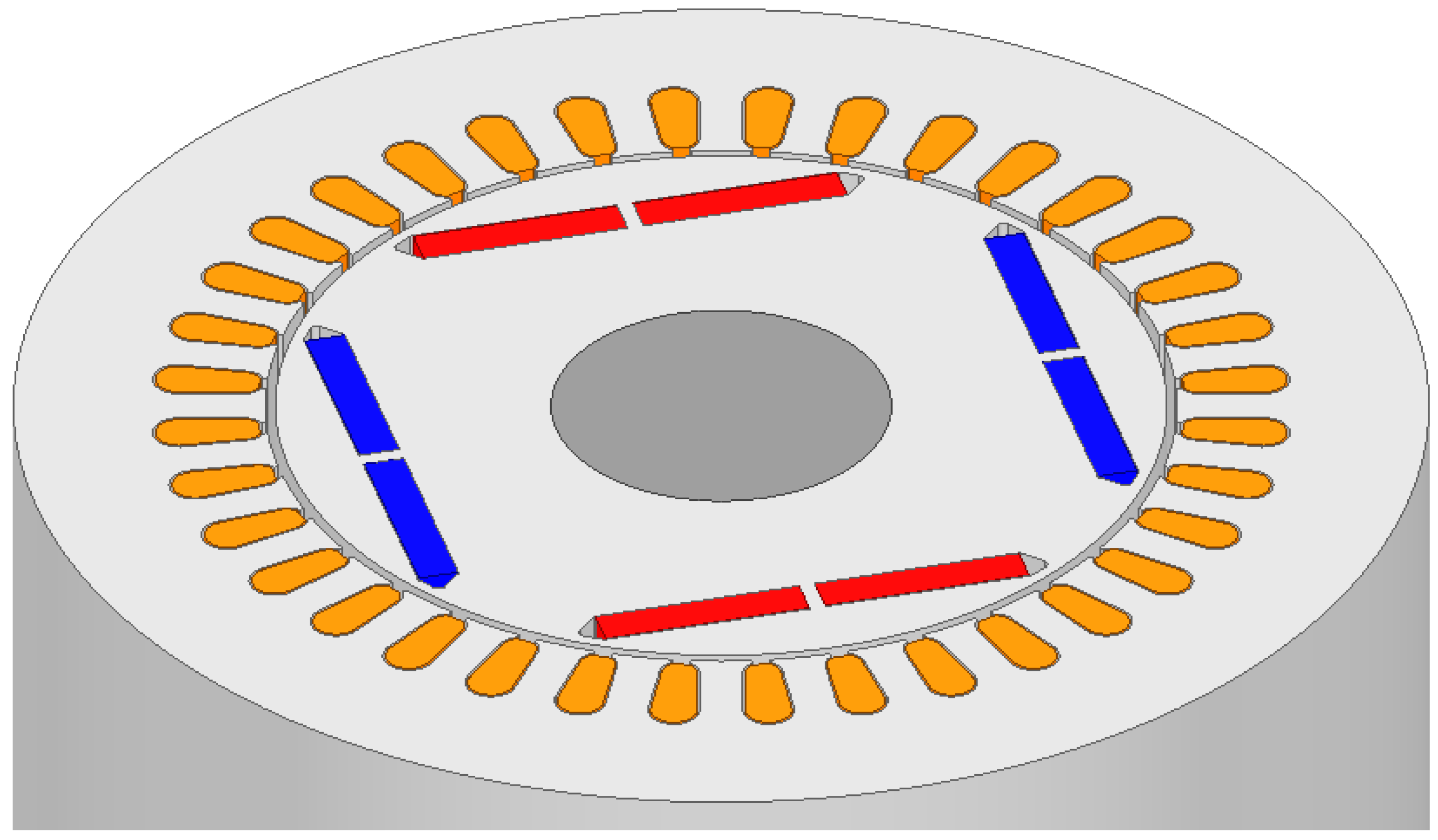
In order to determine the parasitic capacitances of an electric machine, a three-dimensional simulation model of a synchronous machine with permanent magnets placed inside the rotor (IPM) was developed. The choice of such a machine model is due to the numerous advantages of such design. These include, first of all, the presence of a reluctance torque, which interacts with the torque produced by the permanent magnets [
36]. The reason for the presence of the reluctance torque is the magnetic asymmetry of the rotor, since the reluctances for the armature interaction fluxes in the direct and quadrature axes are not equal. Compared to machines with SPM rotors, IPM rotors have a higher torque overload and also do not require additional protection against the effects of centrifugal force on the magnets.
Traditional methods for the analytical determination of parasitic capacitances are being replaced by modern numerical methods more and more often. Nowadays, among the increasingly used numerical methods intended, among other things, for calculating the parameters of electrical machines is the finite element method. With this method, it is possible to develop models of electrical machines that take into account multivariate design changes without the need to build costly prototypes [
37]. A certain limitation in determining parameters in this way is the relatively long calculation time, especially in cases where three-dimensional models of electrical machines are investigated.
In order to analyze the effect of shielding windings on parasitic capacitances and bearing voltages in the machine, it was decided to conduct a series of analyses based on simulations of three-dimensional FEM models. First, a reference model without shielding windings was developed. Using such a model, the values of the parasitic capacitances of the machine were determined, which was the starting point for the analysis of the effect of different shielding winding designs on the parasitic capacitances and BVR coefficients. The purpose of such a comparative analysis is to try to answer the question “which of the analyzed variants has the greatest effectiveness in reducing dangerous bearing voltages”.
4.1. Calculation of Parasitic Capacitances for the Reference Machine Model
The developed reference model lacks solutions that would limit the value of capacitance
Cwr, and it is treated as a starting model for further analysis. The model was developed based on the design data of the actual machine shown in
Table 1. The basic dimensions of the machine are shown in
Figure 8. The stator winding was modeled as a single geometric solid, which significantly simplified the model and made it possible to reduce the number of mesh elements. It is practically impossible to model all the wires of the stator winding with their mutual alignment in a three-dimensional model. The construction of the model and calculations to determine the parasitic capacitances of the machine were performed in the Ansys Maxwell environment using an electrostatic solver. The calculations presented in the paper were carried out using a workstation equipped with a 32-core processor (Threadripper 3970×) supporting a 256 GB quad-channel DDR4 memory controller.
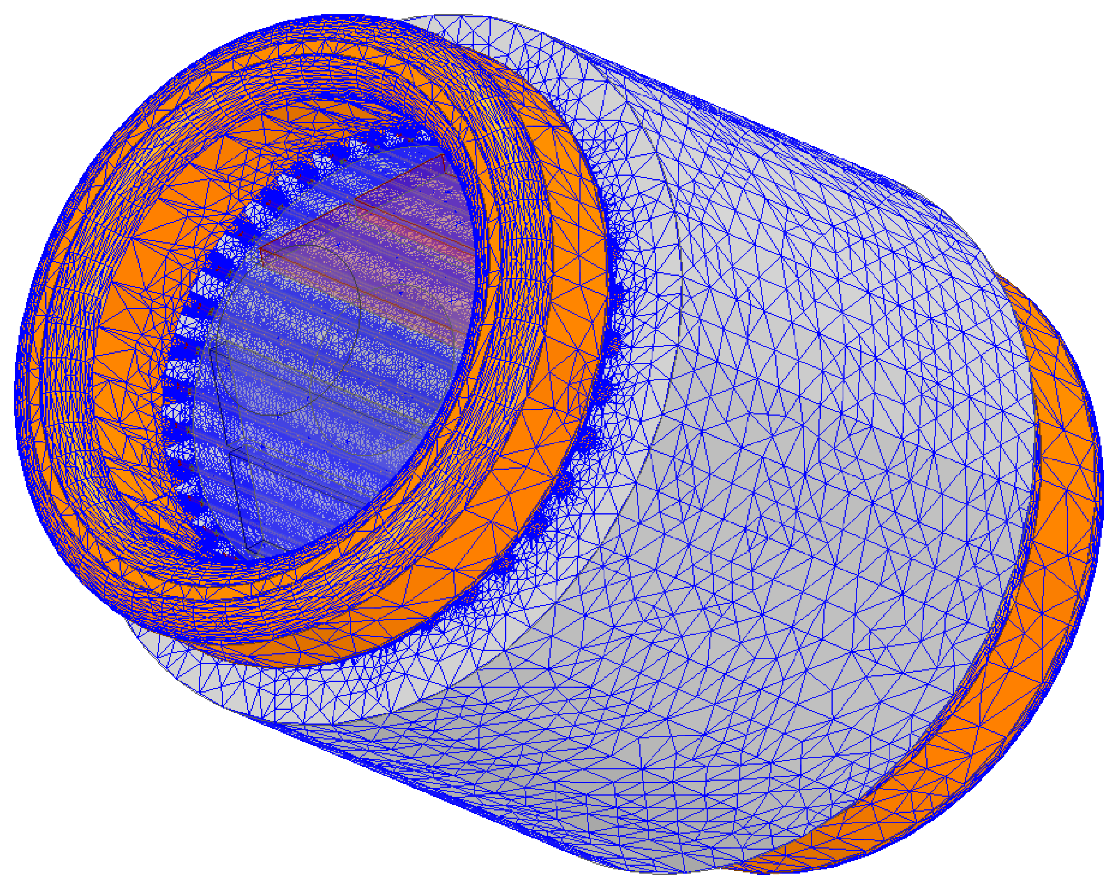
In order to ensure reliable results of the simulation model calculations, the finite element mesh was parameterized in a way that ensures a high density of finite elements in the key spaces of the model, particularly in the space between the stator and the rotor. The generated mesh is shown in
Figure 9. The number of mesh elements was approximately 8.9 million tets.
The presented model is a reference model that was used to determine the parasitic capacitances of the machine: Cwr(ref) = 33.84 pF, Cws(ref) = 4921 pF, Csr(ref) = 324 pF. Such values of capacitances determine the contribution of the bearing voltage in the common-mode voltage defined by the parameter BVR = 6.07%. These values define the starting point for the analysis of the effectiveness of the solutions discussed in the subsequent chapters of the article. The obtained values may differ from the capacitances of the real model, particularly due to the simplification of the winding shape. However, in further simulations, this shape remains unchanged, so the obtained changes in the capacitances values will reflect the actual yield and effectiveness of the analyzed solutions. Since the article provides, among other things, an analysis of the influence of the shielding winding located in the end-windings region, it becomes reasonable to modify the reference model, by means of which it will be possible to calculate the capacitance between the end-windings and the rotor Cwr(ew). The next subsection of the article is dedicated to this issue.
Modified Reference Model
In order to determine the contribution of the
Cwr(slot_ref) and
Cwr(ew_ref) components to the total capacitance
Cwr(ref) between the stator winding and the rotor of the machine under consideration, the simulation model was modified by depriving it of end-windings, as shown in
Figure 10. Using the modified model created in this way made it possible to determine the capacitance
Cwr(slot_ref) of the reference model. The difference in values for the full and modified reference model determines the value of the capacitance that exists between the stator end-windings and the rotor
Cwr(ew_ref):
All model dimensions, except for the end-windings, remained unchanged. The values of the components of the capacitance (
Cwr(ref),
Cwr(slot_ref),
Cwr(ew_ref)) determined for the reference model are presented in
Table 2. The presented values show that the contribution of capacitance in the slot part
Cwr(slot_ref) in relation to the total capacitance
Cwr(ref) amounts to approximately 69%. In view of the above, it is reasonable to shield this machine space, which fits well with the concept of using slot wedges with a shielding winding proposed by the authors, the effectiveness of which is the subject of the studies described in an upcoming part of the article. The ratio of the capacitance components
Cwr(ew) and
Cwr(slot) depends on the geometrical dimensions of the machine’s electromagnetic circuit, particularly on the length of the iron core and the length of the end-winding overhang [
38]. Thus, the ratio will be different for high-speed and low-speed machines.
Next, the modified reference model was supplemented with shielding winding wires placed in slot wedges. Similar to the case above, the model lacked the end-windings. Simulation studies allowed us to determine the effect of using such a shielding winding on the value of capacitance Cwr(slot). In this case, the value of capacitance Cwr(slot) = 3.17 pF was obtained. It means a reduction of this component by 86.5% with respect to the model without shielding windings, which shows the high effectiveness of the suggested solution in reducing the capacitance of Cwr(slot).
4.2. Analysis of the Influence of the Shielding Winding Placed in the Stator Slots on the Parasitic Capacitances of the Machine
According to the previously described concept, the shielding winding was added to the reference model from
Section 4.1, located in the wedges closing the stator slots. This winding consists of 72 copper wires, with 2 wires placed in each wedge, connected in series, as shown in
Figure 11.
The analysis of the effect of the shielding winding was carried out in two variants. The first variant involved studying the effect of the diameter of the wire forming the shielding winding on the parasitic capacitances of the machine. The range of these changes was from 0.45 to 0.6 mm.
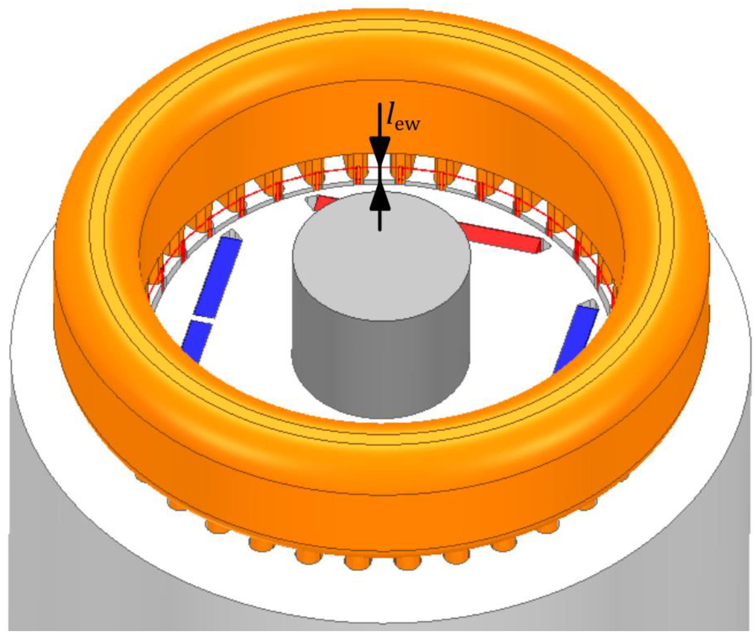
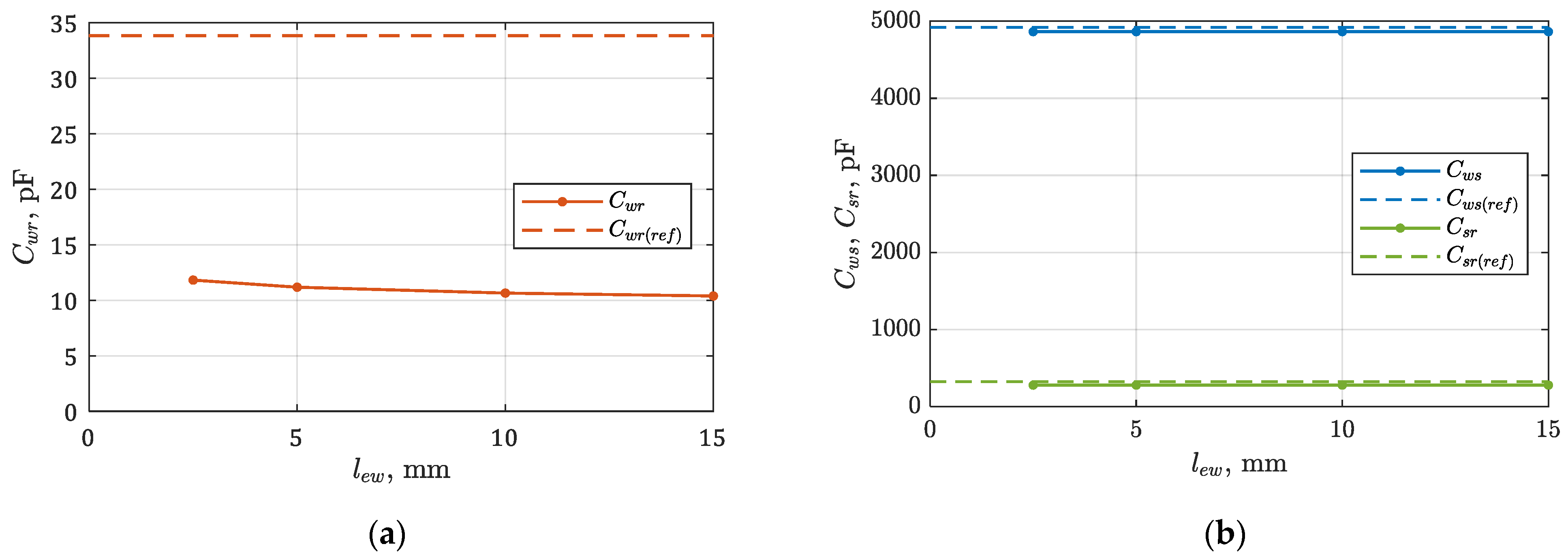
Figure 12 shows the characteristics of the changes in these capacitances. The second variant of calculations concerned the analysis of the effect of the length of end-windings overhang in range from 2.5 to 15 mm. The results of these calculations are shown in
Figure 13. For each of the analyzed cases, the number of mesh elements slightly differed and ranged from 22 to 28 million tets. Such a large number of elements resulted from, among other thing, the small diameters of the shielding wires used.
On the basis of the performed calculations, it can be concluded that the use of the shielding winding located in the stator slot wedges reduces the value of the capacitance Cwr compared to the same capacitance determined for the reference model. The reduction in this capacitance in relation to the reference model ranges from 65.0 to 69.3%, depending on the analyzed calculation variants. The values of the remaining capacitances Cws and Csr are practically insensitive to changes in the parameters lew and dw. The reduction in the Cwr capacitance along with the increase in the diameter of the shielding wires result from the increasing filling of the slot opening space by the grounded shielding winding. The connections of the shielding winding are located under the stator end-windings; hence, with the increase in the lew parameter, a non-significant reduction in the capacitance Cwr can be observed.
4.3. Analysis of the Effect of a Shielding Winding Placed in the End-Winding Region on the Parasitic Capacitances of the Machine
The solution based on the shielding winding placed in the slot wedges, due to its location, noticeably reduces the value of the capacitance component
Cwr(slot) and only slightly reduces the value of the component
Cwr(ew). As previously shown, the
Cwr(ew) capacitance is approximately 30% of the total
Cwr capacitance. In view of the above, it is reasonable to study the impact of the effect of an additional winding, placed at the end-windings. For this purpose, the reference model was supplemented with an additional helix winding made of copper wires located on both sides of the stator iron core, as shown in
Figure 14. The diameter of the helix shielding winding is
dw = 0.5 mm. This helix was placed at a distance of
h1 = 4.0 mm from the stator iron core, and its pitch is
yhelix = 2 mm. The simulations were carried out for a different number of helix turns:
nhelix = 3 ÷ 6, and the results of the obtained parasitic capacitances of the machine are shown in
Figure 15a,b.
Due to the location of the helix shielding winding (directly under the end-winding, at a distance of h1 = 4.0 mm from the stator iron core), its contribution to the reduction in the capacitance component Cwr(slot) is negligible. The change in capacitance Cwr caused by this winding refers to a reduction in the capacitance component of Cwr(ew) by 5.62 pF (54%) for nhelix = 3 and by 7.70 pF (74%) for nhelix = 6.
4.4. Determination of Parasitic Capacitances for the Final Machine Model
The last studied variant is the solution that uses both shielding windings described in the previous sections. In the case of the winding placed in the slot wedges, it was decided to have a minimum overhang length of the shielding winding
lew = 2.5 mm (in order to provide space for the placement of the winding in the form of a helix), and the value of the diameter of the shielding wire
dw = 0.5 mm. In the case of the shielding winding, it was limited to a helix with the number of turns
nhelix = 4. The model developed in this way is shown in
Figure 16. Due to the presence of a large number of objects and small geometric dimensions, the model is characterized by a large number of mesh elements—more than 33 million tets. Since the number of finite elements is so high, the calculation time is very long; for the presented variant, the calculations lasted almost 8.5 days. The values of the obtained parasitic capacitances are shown in
Table 3.
4.5. Summary
In summary, the obtained results were limited to four variants:
Ref.—reference model without any solutions reducing the Cwr capacitance;
Var. A—model with shielding windings in stator slots, dw = 0.5 mm, lew = 2.5 mm;
Var. B—model with helix shielding winding, nhelix = 4;
Var. C—model with shielding winding in stator slots, dw = 0.5 mm, lew = 2.5 mm, and with helix shielding winding, nhelix = 4 (Var. A + Var. B).
The values of capacitance
Cwr and BVR coefficients for the mentioned design variants are compared graphically in
Figure 17a,b. They show that the effective solution is the shielding winding located in the stator slots. It makes it possible to significantly reduce the capacitance
Cwr and, consequently, the BVR coefficient. Its effectiveness can be further improved by adding a helix winding placed from the inside of the stator end-windings. If only the helix winding is used, the effect is unsatisfactory. It is also worth noting that the overall impact on the reduction in
Cwr for variants A and B is greater than that for variant C. To determine the value of the BVR coefficient, the bearing capacitances
Cb1 =
Cb2 = 100 pF were used.
6. Conclusions
The source of the bearing voltage is primarily the asymmetrical nature of the voltage that occurs when the machine is powered from a power electronic converter. In order to reduce the negative effects associated with it, the authors suggest the use of two additional shielding windings in the machine. The main advantage of the suggested solutions is that there is no need to redesign the magnetic core of the machine.
The only fundamental change is to equip the machine with stator slot wedges in which the wires are placed, which, from the technological point of view, is a relatively easy task to perform. This solution is also supported by technical reasons—the grounded shielding winding is protected from short-circuiting to the main winding located in the stator slots.
From the presented calculations of bearing voltages, it can be seen that the use of a shielding winding placed in the stator slot wedges causes a reduction in the value of the capacitance Cwr, resulting in a decrease in the amplitude of the bearing voltage from 17.2 V to 6.8 V.
Simulation research has shown that the overhang length of the shielding winding does not significantly reduce the resultant capacitance Cwr. Therefore, for technological reasons, it is reasonable to use the shortest possible connections between wedges. It reduces the problems of ensuring the electrical insulation of these connections and also has a beneficial effect on their stiffness.
If the above solution turns out to be insufficient from the point of view of bearing voltage levels, equipping the machine with a helix-shaped shielding winding located in stator end-winding region may be considered. This solution, together with the shielding winding in wedges, increases the effectiveness of the bearing voltage limitation. Compared to the reference model, the bearing voltage amplitudes were reduced from 17.2 V to 4.7 V (when the machine is powered from a conventional two-level converter).
The calculations obtained using converter circuit models showed that the method of limiting bearing voltages can additionally be successfully combined with other available methods. For example, when the levels of bearing voltages cause their accelerated wear, it is possible to additionally consider the use of a three-level converter to power the machine. For this supply type, the bearing voltage amplitudes of the machine under consideration were reduced to about 3.1 V.
Due to the nature of the 3D FEM models used, capacitance calculations are time-consuming. The most time-consuming variant turned out to be the model with two shielding windings—for this model, calculations took more than 8 days. For the other cases, the calculations were correspondingly shorter.
The presented results of the simulations justify the desirability of using shielding windings in machines powered by converters, particularly where the high operational reliability of drive systems is required.


