Review

Hybrid Indirect Evaporative Cooling-Mechanical Vapor Compression System: A Mini-Review

1
Water Desalination and Reuse Center, Biological and Environmental Science and Engineering Division, King Abdullah University of Science and Technology, Thuwal 23955, Saudi Arabia
2
Institute for Ocean Engineering, Shenzhen International Graduate School, Tsinghua University, Shenzhen 518055, China
3
Department of Mechanical and Construction Engineering, Northumbria University, Newcastle upon Tyne NE1 8ST, UK
4
School of Mechanical Engineering, Beijing Institute of Technology, Beijing 100081, China
5
Institute of Building Environment and Sustainable Technology, Xi’an Jiaotong University, Xi’an 710049, China
*
Authors to whom correspondence should be addressed.
Energies 2022, 15(20), 7810; https://doi.org/10.3390/en15207810
Submission received: 18 September 2022 / Revised: 10 October 2022 / Accepted: 14 October 2022 / Published: 21 October 2022
(This article belongs to the Special Issue Research and Development on Indirect Evaporative Cooling Technology)

Abstract

:
The hybrid indirect evaporative cooling-mechanical vapor compression (IEC-MVC) process is deemed a promising cooling system for hot and humid areas. It possesses the merits of high energy efficiency and strong capability of temperature and humidity control. Herein, we provide an overview of the state-of-the-art investigations over different aspects of the hybrid IEC-MVC process. Firstly, we evaluate the potential of IEC as a pre-cooler and heat-recovery device. Then, we compare the energy efficiency of IEC-MVC with standalone MVC and summarize its long-term energy-saving potential under specific weather conditions. Subsequently, we discuss the economic viability and water consumption of the hybrid process. These studies form a solid foundation for the future installation of the IEC-MVC system.

1. Introduction

The requirement for better indoor thermal comfort has been increasing due to the desire for higher living standards [1]. Consequently, air-conditioning (AC) has become a basic demand in daily life. In hot regions like the Gulf region, AC has always been a part of the life cycle [2]. For other regions with moderate climate conditions, the demand for AC is also increasing rapidly due to climate change [3,4]. The high demand for AC results in substantial amounts of energy consumption. It is projected by the International Energy Agency (IEA) that the electricity consumption for AC will grow by 3–6 times by 2050, approaching 6000 TWh [5,6].
The most widely used AC technology is based on the mechanical vapor compression cycle (MVC). The merits of MVC include high technology maturity, high robustness, and low costs. However, the specific energy consumption of MVC has stagnated at 0.85 ± 0.02 kW/Rton for a few decades, and further improvement in energy efficiency is becoming more and more difficult [2,7]. Other novel technologies like absorption and adsorption chillers have also emerged, but they are energy intensive and are only competitive in places with waste heat [8,9,10,11]. With the objectives of reducing energy consumption and carbon emission, the industry has a strong motivation to develop more sustainable AC technologies.
The indirect evaporative cooler (IEC) is deemed a promising alternative to MVC in cooling applications [12]. It uses water evaporation as the driving force for cooling and requires little energy input. The energy efficiency of IEC, expressed as the coefficient of performance (COP), is several times higher than that of MVC [13]. Other merits of IEC include simplicity of design and operation. In the past few decades, IEC has been the subject of great research interest. Comprehensive reviews of the most recent advances of IEC are widely available in the literature [14,15,16,17].
Despite the great potential for energy saving, IEC has some intrinsic limitations. Firstly, its performance degrades severely with increasing ambient humidity, making it unsuitable for humid areas. Secondly, IEC is a passive cooler and has little control over supply air conditions. To overcome these limitations, recent research efforts have focused on the integration of IEC with MVC. The hybrid process combines the advantages of both systems and is applicable in most climatic conditions. Experimental and theoretical studies on the hybrid IEC-MVC process have been reported by many researchers, and several review papers on IEC (e.g., [15]) have also mentioned IEC-MVC hybridization in specific sections. However, there exists no systematic summarization and analysis of the existing research efforts. Moreover, several key aspects of IEC-MVC are missing in the existing reviews, such as water consumption and economic viability.
This paper is intended to provide a comprehensive review of recent studies of the hybrid IEC-MVC process. The working principles of IEC and IEC-MVC will be introduced first. Then, existing efforts on IEC-MVC will be summarized in three aspects, namely, (i) evaluating IEC as a pre-cooler and heat-recovery device, (ii) comparing the energy efficiency of IEC-MVC with standalone MVC, and (iii) predicting the long-term energy-saving potential of IEC-MVC in specific weather conditions. Afterward, the economic viability and water consumption of IEC-MVC will be discussed. Finally, key conclusions and future perspectives will be presented.

2. Working Principles of IEC

A conventional IEC consists of alternating dry and wet channels, as shown in Figure 1. Water is supplied to the wet channels and contacts with the working air (3). Due to the difference in moisture content between the sprayed water and the working air, water evaporates and cools the channel plates. Meanwhile, the product air (1) passes through the dry channels and is cooled by the plate through convective heat transfer. A schematic illustration of this process in the psychrometric chart is also provided in Figure 1. During the cooling process, there is no moisture added to the product air, and the supply air temperature (2) can approach the wet bulb temperature of the working air.
To achieve lower product air temperature, two variations of IEC have been proposed, namely, regenerative indirect evaporative cooler (RIEC) [18,19] and Maisotsenko-cycle (M-cycle) cooler [20,21], as shown in Figure 2. Both configurations split a portion of the cooled air from the dry channels to the wet channels. In RIEC, air split happens at the exit of the dry channels (2), while in an M-cycle cooler, air split happens in several locations along the channels (a–e). Due to the pre-cooling of working air in the dry channels, its wet bulb temperature is reduced, and the product air (2) has the potential to approach the dew point temperature of the inlet air (1).
Most IECs are flat-plate heat exchangers with cross-flow, counter-flow, or hexagon configurations [22,23,24]. Several novel configurations have also been proposed, such as tubular IEC [15,25] and heat-pipe IEC [26,27]. Other efforts to improve IEC performance include adding internal structures [28,29,30,31,32] and exploring new materials [33,34,35,36]. However, the performance of IEC is still limited by the outdoor air humidity, and the desired temperature cannot be achieved if the ambient humidity is high [37]. To overcome such a limitation, several researchers have integrated dehumidifiers (including liquid desiccant [38,39,40] and desiccant wheel [41,42]) with IEC. As illustrated in Figure 3, the moisture content of the air is first removed by the dehumidifier, and then the dry air is cooled to the desired temperature using IEC. The combined desiccant dehumidifier + IEC system was found to be 10–18% more energy efficient than the traditional mechanical chiller [43], but the energy efficiency is not as promising as the standalone IEC [44]. The main reason is that most dehumidifiers are energy-intensive and their COPs are usually lower than 1 [45].

3. Hybrid IEC-MVC Process

To achieve better cooling performance, the hybridization of IEC with MVC has been proposed. A schematic chart of the hybrid process is shown in Figure 4 [46]. In this hybrid configuration, the outdoor air is first pre-cooled by the IEC, and then it is further processed by MVC to achieve the desired temperature and humidity. The exhaust air from the indoor conditioned spaces is usually supplied to the wet channels as the working air to recover the cold energy. Therefore, IEC functions as both the pre-cooler and the energy recovery device. The advantages of the hybrid IEC-MVC process are very obvious. It combines IEC’s high energy efficiency and MVC’s capability of temperature and humidity control, making it applicable in different climatic conditions. Therefore, it is considered the most promising cooling technology and has become the subject of great research interest.
In the following subsections, the potential of IEC as a pre-cooler and heat-recovery device will be evaluated first. Then, the energy efficiency of IEC-MVC will be compared with that of standalone MVC. After that, the long-term energy-saving potential of IEC-MVC will be discussed under specific weather conditions.

3.1. IEC for Pre-Cooling and Heat Recovery

Following previous studies on IEC, it is easy to evaluate IEC as a pre-cooler of MVC and an energy-recovery device. The main difference of the IEC pre-cooler is that condensation may occur in the dry channels. To capture this unique feature, Chen et al. [37,47,48] developed a simplified analytical model for IEC considering different condensation states in the dry channels, namely, non-condensation, partial condensation, and total condensation. Non-condensation occurs when the plate surface temperature is always higher than the dew-point temperature of the product air, while total condensation occurs when the plate temperature is lower than the dew-point temperature. The partial condensation state happens when the outdoor air is initially unsaturated but gradually cools to below the dew point temperature. The schematics of the three condensation states are illustrated in Figure 5. The authors first modified the heat transfer coefficient and specific heat capacity to extend their applicability to wet surfaces. Then, a method for judging the three condensation states was established. Finally, the electricity consumption of fans and pumps was modeled for evaluating energy efficiency.
To better describe the condensation situations, Zheng et al. [49] developed a two-dimensional cross-flow IEC model considering condensation. The model was solved using the finite element method, and heat and mass transfer coefficients were assumed to be constant. A test rig with visualized air channels was developed to validate the model, as shown in Figure 6. The results revealed that condensation is more likely to occur near the outlet of the dry channels. Up to 30% of the moisture was removed in the dry channels, and the condensation heat reached 3.9 kW.
You et al. [50] developed a three-dimensional numerical model for a cross-flow plate IEC. The effects of the mass transfer time relaxation parameter on supply air temperature and humidity were tested first, and a fitting equation was developed based on the testing results. The fitting equation was then employed in a three-dimensional model to predict IEC performance, and the error was observed to be within ±10%.
In addition to the abovementioned analytical models, other approaches have also been proposed. For example, Pandelidis et al. [51] established an ε-NTU model to evaluate the heat and mass transfer in a heat-recovery IEC. The balances of heat and mass were calculated using ordinary differential equations, and the model was solved using the finite element method. In each element, the air temperature was compared with its dew point temperature at each iteration step to determine whether condensation occurs. In another study, a statistical model was developed to study IEC as an energy-recovery device [52]. The flow chart for model development is illustrated in Figure 7. Numerical simulations were first carried out to generate data under different operating conditions. The data were used to train a decision model that identifies the occurrence of condensation. Afterward, a two-level factorial design was performed to develop correlations to predict IEC performance under different condensation states. The model predicted the wet-bulb efficiency within 9.52% errors.
Based on the developed models, the energy-saving potential of using IEC as a pre-cooler was evaluated. For example, Cui et al. [53] estimated a RIEC as a pre-cooling device of MVC under humid outdoor conditions. The outdoor air temperature varied between 30 and 35 °C, and the relative humidity was 70–90%. The outdoor air temperature can be reduced by 7.2–11.7 °C, and the air humidity ratio also decreases by 2.9–11.6 g/kg. The RIEC handles 35–47% of the total cooling load from the outdoor humid air, and the energy-saving potential is significant.
Experimental studies on IEC as a pre-cooler have also been conducted. Chen et al. [46] tested a hexagon IEC as an energy-recovery device from room exhaust air. The outdoor temperature and humidity ranges were 30–42 °C and 13–20 g/kg, respectively, while the room air condition was 23 ± 1 °C and 11 ± 1 g/kg. Under the operating conditions considered, the outdoor air temperature and humidity ratio can be reduced by 6–15 °C and 0.5–4 g/kg, respectively. To quantify the energy recovery performance, a parameter named effectiveness of enthalpy recovery was introduced, which is expressed as
ε = min h 1 h 2 h 1 h 2 , s , h 5 h 4 h 5 , s h 4
The subscriptions refer to the locations illustrated in Figure 4. h 2 , s represents the minimum enthalpy that can be achieved by the outdoor air, i.e., it reaches the same temperature as the room air. Similarly, h 5 , s is the theoretical maximum enthalpy of the purge air and is achieved when the purge air reaches the outdoor air temperature and its RH is 100%. Based on the test data, the effectiveness was correlated to the main operating parameters (outdoor temperature and humidity, room air temperature and humidity, and air flowrates):
ε = 0.416 5.81 × 10 3 T O A + 4.65 × 10 3 ω O A + 1.42 × 10 3 T R A 5.65 × 10 3 ω R A + 7.49 × 10 4 m ˙ o a m ˙ R A
From these research efforts, the potential of IEC as a pre-cooler and energy-recovery device has been demonstrated. Such potential provides strong motivations for further studies into the hybrid IEC-MVC process, which will be discussed in the next subsection.

3.2. Comparison with Standalone MVC

After the potential of IEC as a pre-cooler was demonstrated, the hybrid IEC-MVC system was commissioned and tested. Chen et al. [54] developed a 1-Rton IEC-MVC unit at King Abdullah University of Science and Technology (KAUST). As shown in Figure 8, the unit consists of a hexagon IEC and an MVC chiller that are connected in series. Tests were conducted at outdoor temperature ranges of 30–40 °C and humidity ranges of 10–20 g/kg. The final supply air temperature can be regulated over a wide range by changing the compressor frequency and the air flowrate. Such temperature control capability can never be realized using IEC alone. The COP of the hybrid process was 15–35% higher than the standalone MVC under the same conditions. Based on the test results, an empirical model was developed for quick estimation of IEC-MVC performance.
Similar efforts were reported by Delfani et al. [55], who connected an IEC unit with a packed-unit air-conditioner (PUA). Two air simulators were employed to simulate the outdoor and indoor conditions, as shown in Figure 9. The system was tested under temperature and humidity ranges of 27–45 and 2–16 g/kg, respectively, which covers the weather conditions of four major cities in Iran (Tehran, Bam, Tabas, and Yazd). IEC was observed to handle 75% of the cooling load, and the electricity can be reduced by up to 55%.
In addition to regular IEC, the M-cycle was also integrated with MVC. Zanchini and Naldi [56] evaluated the energy-saving potential of using an M-cycle cooler as a pre-cooler of MVC. The hourly needs of cooling and dehumidification in a real office building in Milan were considered during July and August. Two configurations were considered: one using M-cycle cooler to pre-cool the outdoor air and the other using M-cycle cooler to cool recirculated air. The latter configuration, as shown in Figure 10, demonstrated better performance, and the total electricity was reduced by 38%.
The abovementioned studies verified the energy-saving potential of the hybrid IEC-MVC process. However, most results are limited to the lab scale with fixed operating conditions, and the actual savings over the whole year requires further validation, which will be addressed in the next subsection.

3.3. Long-Term Performance Prediction

As the energy saving of IEC-MVC is highly dependent on climatic conditions, it is needed to consider long-term operation. Chen et al. [15,57] evaluated the seasonal performance of a hybrid IEC-MVC in a wet market in Hong Kong. As the air in the market contains moisture and smell, it cannot be reused and 100% fresh air (5112 m3/h/AHU) has to be considered. The annual electricity savings is predicted to be 70,000 kWh, as compared to 40,000 kWh for the rotating wheel. Based on the test data, a mathematical model was developed and validated, and then annual simulations were conducted for eight selected cities in southern China (Haikou, Shantou, Hong Kong, Nanning, Guangzhou, Fuzhou, Changsha, and Wenzhou) [58]. The annual energy savings ranged from 14.4% to 26.4%.
Duan et al. [59] evaluated a hybrid RIEC-MVC system for an office building in Beijing. As shown in Figure 11, the room return air is mixed with the outdoor air and then supplied to the RIEC dry channels. After pre-cooling, the air is split into two streams: one is further cooled in the evaporator and supplied to the room, and the other is firstly directed to the wet channels as the working air and then passes through the condenser to remove condensation heat. A dynamic model is developed using EnergyPlus, and the annual system performance was evaluated under the weather conditions of Beijing. An energy saving of 38.2% was observed.
Chen et al. [54] evaluated a 1-Rton IEC-MVC unit under the climatic conditions of Saudi Arabia. To quantify the need for cooling and dehumidification, two parameters were introduced, namely, cooling degree hours (CDH) and dehumidifying gram hours (DGM). The former accumulates the annual need for cooling on an hourly basis, while the latter adds up the hourly need for dehumidification:
C D H = T h o u r 18 ° C   w h e n   T > 18 ° C
D G H = ω h o u r 9   g / kg   w h e n   ω > 9   g / kg
Analytical results revealed that IEC-MVC shows the maximum energy savings in hot and humid cities that have high CDH and low DGM, and up to 40–60% of energy saving was observed.
Cui et al. [60] theoretically evaluated the energy-saving potential of IEC-MVC under the design conditions of five cities, as summarized in Figure 12. Hourly simulations demonstrated significant energy savings for the hybrid system when treating outdoor air: 38% for Singapore, 49% for Cairo, 47% for Florence, 45% for Athens, and 35% for Xi’an.
The long-term analyses further validated the advantages of IEC-MVC over existing AC systems. Although the actual numbers vary in different cities, more than 30% of savings in electricity consumption can be achieved in most cities considered. Such savings will significantly reduce primary energy consumption and the corresponding carbon emissions, thus forming a strong thrust for the commercialization of this new technology.

4. Discussions

Although the energy-saving potential of the hybrid IEC-MVC process has been well demonstrated, other important factors also need to be considered for realizing the future commercialization of this new technology. The first concern is water consumption. As the evaporation of water is the source of the cooling effect, water consumption is significant in areas with a high sensible cooling load. Ali et al. [61] estimated the annual water consumption of an M-cycle cooler in Riyadh, a city located at the center of the desert. The benchmark building had a floor area of 97.1 m2 and the average height was 2.8 m. For the summer months, the water consumption can reach 10 m3/month. Chen et al. [54] also mated the water consumption of IEC in Riyadh, and the annual water consumption was 75 m3 assuming an outdoor air flowrate of 1 kg/s. Such water consumption is a great burden in arid areas that face severe water scarcity.
A common way to reduce water consumption is to recover the condensate from the MVC unit. As shown in Figure 13, the moisture content is condensed in the MVC evaporator when outdoor air is humid, and the condensate can be supplied to the IEC wet channels as part of the water source [15,57]. In cities with moderate humidity, the recovered condensate is almost sufficient for IEC consumption. For example, in Dhahran, (a city in eastern Saudi Arabia, CDH = 899,671 °C-h/year, DGH = 22,225 g-h/year), the annual average water consumption is 9.15 L/h for processing 1 kg/s of outdoor air, while the recovered condensate is 8.25 L/h [54]. In cities with higher humidity (e.g., Jazan, Saudi Arabia, CDH = 899,671 °C-h/year, DGH = 22,225 g-h/year), the amount of collected condensate is twice that of water consumption, and extra water can be used elsewhere [54]. A summary of water consumption and condensation amounts is provided in Table 1.
In coastal cities, IEC can also be modified for desalination applications to get fresh water. As illustrated in Figure 14, the exhaust air from the wet channels of IEC can be supplied to a humidification–dehumidification desalination (HDH) system [62,63]. As the exhaust air has higher moisture content and lower temperature than the ambient air, seawater evaporation will be promoted in the HDH cycle, leading to more freshwater production. Analytical results reveal that the water productivity of the hybrid IEC-HDH cycle is >60% higher than standalone HDH under the same heat input [62]. Moreover, the amount of water produced in the IEC is several times higher than the water consumption of the IEC. Thus, the hybrid IEC-HDH cycle is an ideal solution for the simultaneous production of fresh water and cooling effects.
In addition to desalination, the water source for IEC can also be provided by the atmospheric water harvesting (AWH) process. AWH collects water from the ambient, and various devices have been developed to produce water in different geographical locations with varying humidity levels [64]. One important method for AWH is to cool the air to its dew point temperature, and a cooling effect is also produced during this process [65]. Therefore, optimal integration of IEC-MVC with AWH potentially provides more promising solutions for cooling and water production.
Another concern of the hybrid system is its economic viability. According to the limited literature that involved cost analysis, the IEC-MVC system is not always economically promising. For example, the payback period was estimated to be 2.9 years for the case of a wet market in Hong Kong [15,57], while for the case of Beijing the payback period is as long as 18 years [59]. The factors that determine the payback period include ambient conditions, annual cooling need, sensible/latent cooling load ratio, electricity and water prices, etc. A thorough life-cycle cost analysis based on long-term operation data is required for evaluating the economic viability of IEC-MVC in each city.

5. Conclusions and Future Perspectives

This article presents a comprehensive review of the hybrid IEC-MVC system. Standalone IEC as the pre-cooler and the hybrid IEC-MVC system are described in terms of theoretical modeling, experimental demonstration, energy-saving analysis, long-term potential, economic viability, and water consumption. Key findings are summarized as follows:
(1)
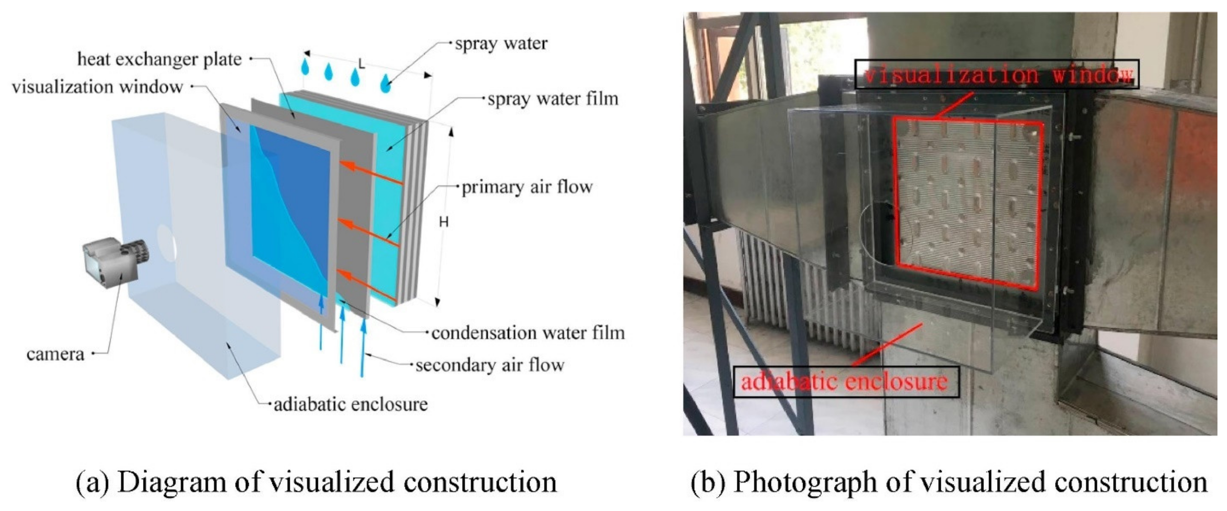
When IEC works as a pre-cooler and heat recovery device, a major difference with the regular IEC is the occurrence of condensation in dry channels. Analytical IEC models considering condensation, including one-dimensional, two-dimensional, and three-dimensional models, have achieved high accuracy. Mathematical analyses revealed that IEC can handle 35–47% of the total cooling load;
(2)
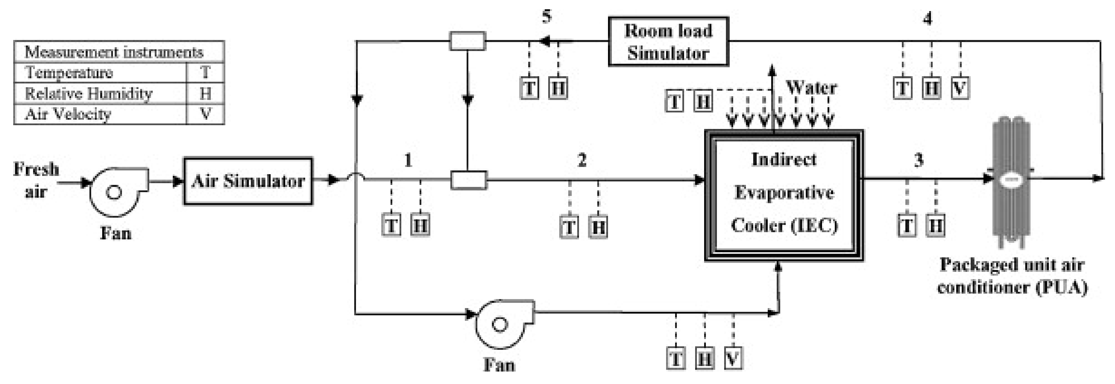
The energy-saving potential of IEC-MVC over standalone MVC has been demonstrated experimentally and analytically. Depending on the design and operation conditions, the energy consumption of IEC-MVC is 15–55% lower than that of standalone MVC;
(3)
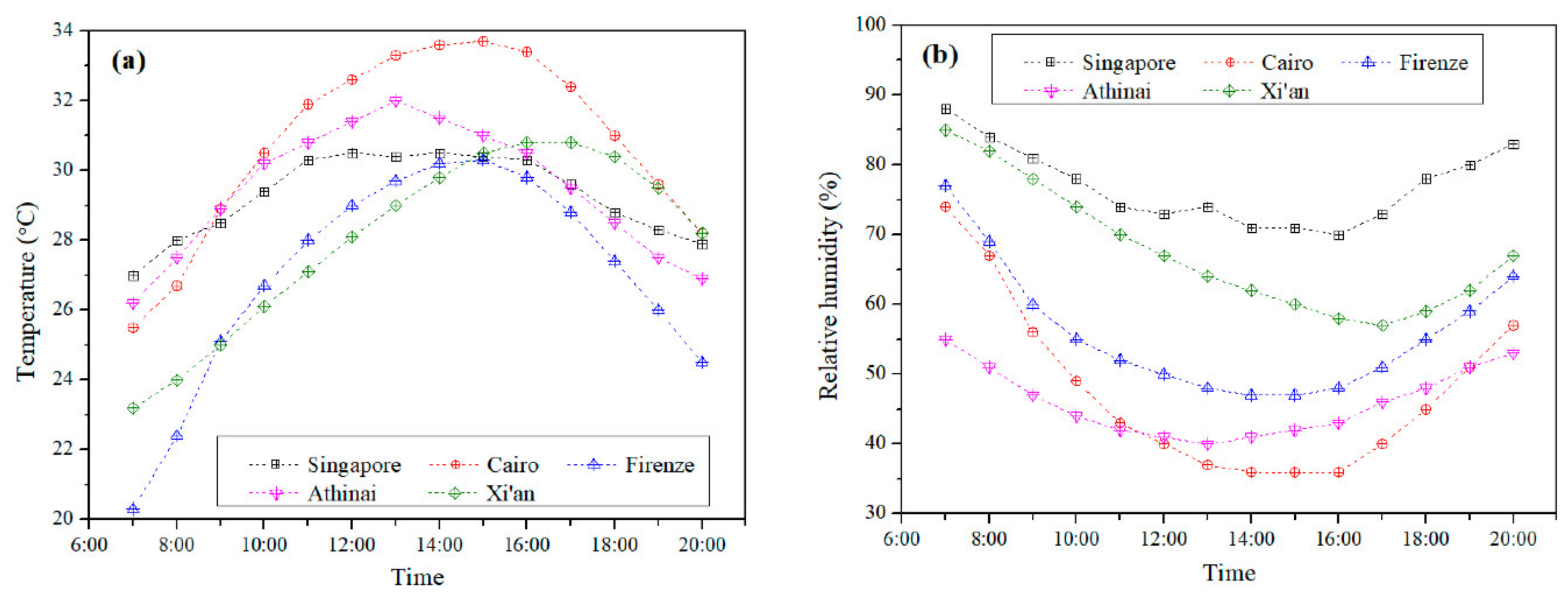
The long-term performance of IEC-MVC has been evaluated using annual weather data. The calculations cover many cities in different countries, including China, Saudi Arabia, and Europe. In humid cities like Hong Kong, the energy savings is moderate at 14–26%. On the other hand, for arid cities in Saudi Arabia, the energy savings can reach 60%;
(4)
Water consumption of IEC is significant, especially in areas with a high sensible load. The condensate produced in the MVC can be recovered as part of the water sources. Additionally, IEC can be coupled with desalination systems or atmospheric water harvesters to get fresh water;
(5)
The economic viability of IEC-MVC varies with climatic conditions as well as water and electricity prices. A robust life-cycle analysis based on long-term operation data is required to quantify the economic viability of the hybrid system.
Although the hybrid IEC-MVC process has shown great energy-saving potential, field test data and reliable cost analyses are scarce. These aspects will be the focus of future studies. In addition, the improvement of IEC and MVC will also contribute to wider applications of the IEC-MVC system in air conditioning for commercial, industrial, and residential sectors. The authors believe the quantum improvement in electricity savings is one of the keys to future sustainable air conditioning globally.

Author Contributions

Conceptualization, Q.C.; methodology, M.B. and M.K.J.; formal analysis, M.W.S., D.Y., H.Z. and X.C.; writing—original draft preparation, Q.C.; writing—review and editing, Q.C. and K.C.N.; visualization, Q.C.; supervision, K.C.N.; project administration, K.C.N.; funding acquisition, K.C.N. All authors have read and agreed to the published version of the manuscript.

Funding

The authors gratefully acknowledge the generous funding from (1) the KAUST Cooling Initiative (KCI) project, REP/1/3988-01-01, (2) the Water Desalination and Reuse Center (WDRC), King Abdullah University of Science and Technology (KAUST), and (3) Shenzhen International Graduate School, Tsinghua University.

Conflicts of Interest

The authors declare no conflict of interest.

Nomenclatures

ACAir-conditioning
AWHAtmospheric water harvesting
CDHCooling degree hours
COPCoefficient of performance
DGMDehumidifying gram hours
HDHHumidification–dehumidification desalination
IEAInternational Energy Agency
IECIndirect evaporative cooling
MVCMechanical vapor compression
NTUNumber of heat transfer units
PUAPacked-unit air-conditioner
R-IECRegenerative indirect evaporative cooling
Symbols
hEnthalpy
TTemperature
mMass flowrate
Greek letters
εEffectiveness
ωHumidity ratio

References

  1. Wu, T.; Cao, B.; Zhu, Y. A field study on thermal comfort and air-conditioning energy use in an office building in Guangzhou. Energy Build. 2018, 168, 428–437. [Google Scholar] [CrossRef]
  2. Shahzad, M.W.; Lin, J.; Bin Xu, B.; Dala, L.; Chen, Q.; Burhan, M.; Sultan, M.; Worek, W.; Ng, K.C. A spatiotemporal indirect evaporative cooler enabled by transiently interceding water mist. Energy 2021, 217, 119352. [Google Scholar] [CrossRef]
  3. Smith, S.T.; Hanby, V.; Harpham, C. A probabilistic analysis of the future potential of evaporative cooling systems in a temperate climate. Energy Build. 2011, 43, 507–516. [Google Scholar] [CrossRef]
  4. Spandagos, C.; Ng, T.L. Equivalent full-load hours for assessing climate change impact on building cooling and heating energy consumption in large Asian cities. Appl. Energy 2017, 189, 352–368. [Google Scholar] [CrossRef]
  5. IEA. The Future of Cooling in China; IEA: Paris, France, 2019. [Google Scholar]
  6. Waite, M.; Cohen, E.; Torbey, H.; Piccirilli, M.; Tian, Y.; Modi, V. Global trends in urban electricity demands for cooling and heating. Energy 2017, 127, 786–802. [Google Scholar] [CrossRef] [Green Version]
  7. Shahzad, M.W.; Burhan, M.; Ybyraiymkul, D.; Oh, S.J.; Ng, K.C. An improved indirect evaporative cooler experimental investigation. Appl. Energy 2019, 256, 113934. [Google Scholar] [CrossRef]
  8. Aliane, A.; Abboudi, S.; Seladji, C.; Guendouz, B. An illustrated review on solar absorption cooling experimental studies. Renew. Sustain. Energy Rev. 2016, 65, 443–458. [Google Scholar] [CrossRef]
  9. Nikbakhti, R.; Wang, X.; Hussein, A.K.; Iranmanesh, A. Absorption cooling systems–Review of various techniques for energy performance enhancement. Alex. Eng. J. 2020, 59, 707–738. [Google Scholar] [CrossRef]
  10. Li, X.H.; Hou, X.H.; Zhang, X.; Yuan, Z.X. A review on development of adsorption cooling—Novel beds and advanced cycles. Energy Convers. Manag. 2015, 94, 221–232. [Google Scholar] [CrossRef]
  11. Mohammed, R.H.; Mesalhy, O.; Elsayed, M.L.; Chow, L.C. Assessment of numerical models in the evaluation of adsorption cooling system performance. Int. J. Refrig. 2019, 99, 166–175. [Google Scholar] [CrossRef]
  12. Yan, W.; Meng, X.; Cui, X.; Liu, Y.; Chen, Q.; Jin, L. Evaporative cooling performance prediction and multi-objective optimization for hollow fiber membrane module using response surface methodology. Appl. Energy 2022, 325, 119855. [Google Scholar] [CrossRef]
  13. Jradi, M.; Riffat, S. Experimental and numerical investigation of a dew-point cooling system for thermal comfort in buildings. Appl. Energy 2014, 132, 524–535. [Google Scholar] [CrossRef]
  14. Duan, Z.; Zhan, C.; Zhang, X.; Mustafa, M.; Zhao, X.; Alimohammadisagvand, B.; Hasan, A. Indirect evaporative cooling: Past, present and future potentials. Energy Rev. 2012, 16, 6823–6850. [Google Scholar] [CrossRef]
  15. Yang, H.; Shi, W.; Chen, Y.; Min, Y. Research development of indirect evaporative cooling technology: An updated review. Renew. Sustain. Energy Rev. 2021, 145, 111082. [Google Scholar] [CrossRef]
  16. Sajjad, U.; Abbas, N.; Hamid, K.; Abbas, S.; Hussain, I.; Ammar, S.M.; Sultan, M.; Ali, H.M.; Hussain, M.; Rehman, T.U.; et al. A review of recent advances in indirect evaporative cooling technology. Heat Mass Transf. 2021, 122, 105140. [Google Scholar] [CrossRef]
  17. Yang, Y.; Cui, G.; Lan, C.Q. Developments in evaporative cooling and enhanced evaporative cooling-A review. Renew. Sustain. Energy Rev. 2019, 113, 109230. [Google Scholar] [CrossRef]
  18. Cui, X.; Islam, M.; Chua, K. An experimental and analytical study of a hybrid air-conditioning system in buildings residing in tropics. Energy Build. 2019, 201, 216–226. [Google Scholar]
  19. Duan, Z.; Zhan, C.; Zhao, X.; Dong, X. Experimental study of a counter-flow regenerative evaporative cooler. Build. Environ. 2016, 104, 47–58. [Google Scholar] [CrossRef]
  20. Baakeem, S.S.; Orfi, J.; Mohamad, A.; Bawazeer, S. The possibility of using a novel dew point air cooling system (M-Cycle) for A/C application in Arab Gulf Countries. Build. Environ. 2019, 148, 185–197. [Google Scholar]
  21. Oh, S.J.; Shahzad, M.W.; Burhan, M.; Chun, W.; Jon, C.K.; Ja, M.K.; Ng, K.C. Approaches to energy efficiency in air conditioning: A comparative study on purge configurations for indirect evaporative cooling. Energy 2019, 168, 505–515. [Google Scholar] [CrossRef]
  22. Min, Y.; Chen, Y.; Yang, H. Numerical study on indirect evaporative coolers considering condensation: A thorough comparison between cross flow and counter flow. Int. J. Heat Mass Transf. 2019, 131, 472–486. [Google Scholar]
  23. Jia, L.; Liu, J.; Wang, C.; Cao, X.; Zhang, Z. Study of the thermal performance of a novel dew point evaporative cooler. Appl. Therm. Eng. 2019, 160, 114069. [Google Scholar] [CrossRef]
  24. Pandelidis, D.; Niemierka, E.; Pacak, A.; Jadwiszczak, P.; Cichoń, A.; Drąg, P.; Worek, W.; Cetin, S. Performance study of a novel dew point evaporative cooler in the climate of central Europe using building simulation tools. Build. Environ. 2020, 181, 107101. [Google Scholar]
  25. Wang, F.; Sun, T.; Huang, X.; Chen, Y.; Yang, H. Experimental research on a novel porous ceramic tube type indirect evaporative cooler. Appl. Therm. Eng. 2017, 125, 1191–1199. [Google Scholar] [CrossRef]
  26. Boukhanouf, R.; Amer, O.; Ibrahim, H.; Calautit, J. Design and performance analysis of a regenerative evaporative cooler for cooling of buildings in arid climates. Build. Environ. 2018, 142, 1–10. [Google Scholar] [CrossRef]
  27. Riffat, S.; Zhu, J. Mathematical model of indirect evaporative cooler using porous ceramic and heat pipe. Appl. Therm. Eng. 2004, 24, 457–470. [Google Scholar] [CrossRef]
  28. Park, J.-Y.; Kim, B.-J.; Yoon, S.-Y.; Byon, Y.-S.; Jeong, J.-W. Experimental analysis of dehumidification performance of an evaporative cooling-assisted internally cooled liquid desiccant dehumidifier. Appl. Energy 2019, 235, 177–185. [Google Scholar] [CrossRef]
  29. Moshari, S.; Heidarinejad, G. Analytical estimation of pressure drop in indirect evaporative coolers for power reduction. Energy Build. 2017, 150, 149–162. [Google Scholar] [CrossRef]
  30. Kabeel, A.; Bassuoni, M.; Abdelgaied, M. Experimental study of a novel integrated system of indirect evaporative cooler with internal baffles and evaporative condenser. Energy Convers. Manag. 2017, 138, 518–525. [Google Scholar]
  31. Kabeel, A.; Abdelgaied, M. Numerical and experimental investigation of a novel configuration of indirect evaporative cooler with internal baffles. Energy Convers. Manag. 2016, 126, 526–536. [Google Scholar] [CrossRef]
  32. Ali, M.; Ahmad, W.; Sheikh, N.A.; Ali, H.; Kousar, R.; Rashid, T.U. Performance enhancement of a cross flow dew point indirect evaporative cooler with circular finned channel geometry. J. Build. Eng. 2021, 35, 101980. [Google Scholar] [CrossRef]
  33. Zhao, X.; Liu, S.; Riffat, S. Comparative study of heat and mass exchanging materials for indirect evaporative cooling systems. Build. Environ. 2008, 43, 1902–1911. [Google Scholar] [CrossRef]
  34. Rashidi, S.; Kashefi, M.H.; Kim, K.C.; Samimi-Abianeh, O. Potentials of porous materials for energy management in heat exchangers–A comprehensive review. Appl. Energy 2019, 243, 206–232. [Google Scholar] [CrossRef]
  35. Boukhanouf, R.; Alharbi, A.; Ibrahim, H.G.; Amer, O.; Worall, M. Computer modelling and experimental investigation of building integrated sub-wet bulb temperature evaporative cooling system. Appl. Therm. Eng. 2017, 115, 201–211. [Google Scholar] [CrossRef] [Green Version]
  36. Lee, J.; Lee, D.-Y. Experimental study of a counter flow regenerative evaporative cooler with finned channels. Int. J. Heat Mass Transf. 2013, 65, 173–179. [Google Scholar] [CrossRef]
  37. Chen, Y.; Yang, H.; Luo, Y. Indirect evaporative cooler considering condensation from primary air: Model development and parameter analysis. Build. Environ. 2016, 95, 330–345. [Google Scholar] [CrossRef]
  38. Cui, X.; Liu, Y.; Liu, Y.; Jin, L.; Zhao, M.; Meng, X. Studying the performance of a liquid desiccant indirect evaporative cooling system. Energy Procedia 2019, 158, 5659–5665. [Google Scholar] [CrossRef]
  39. Cui, X.; Islam, M.; Mohan, B.; Chua, K. Theoretical analysis of a liquid desiccant based indirect evaporative cooling system. Energy 2016, 95, 303–312. [Google Scholar] [CrossRef]
  40. Sohani, A.; Sayyaadi, H.; Balyani, H.H.; Hoseinpoori, S. A novel approach using predictive models for performance analysis of desiccant enhanced evaporative cooling systems. Appl. Therm. Eng. 2016, 107, 227–252. [Google Scholar] [CrossRef]
  41. Heidari, A.; Roshandel, R.; Vakiloroaya, V. An innovative solar assisted desiccant-based evaporative cooling system for co-production of water and cooling in hot and humid climates. Energy Convers. Manag. 2019, 185, 396–409. [Google Scholar] [CrossRef]
  42. Pandelidis, D.; Anisimov, S.; Worek, W.M.; Drąg, P. Comparison of desiccant air conditioning systems with different indirect evaporative air coolers. Energy Convers. Manag. 2016, 117, 375–392. [Google Scholar] [CrossRef]
  43. Lee, S.-J.; Kim, H.-J.; Dong, H.-W.; Jeong, J.-W. Energy saving assessment of a desiccant-enhanced evaporative cooling system in variable air volume applications. Appl. Therm. Eng. 2017, 117, 94–108. [Google Scholar] [CrossRef]
  44. Zhang, F.; Yin, Y.; Zhang, X. Performance analysis of a novel liquid desiccant evaporative cooling fresh air conditioning system with solution recirculation. Build. Environ. 2017, 117, 218–229. [Google Scholar] [CrossRef]
  45. Xiao, L.; Yang, M.; Yuan, W.-Z.; Huang, S.-M. Performance characteristics of a novel internally-cooled plate membrane liquid desiccant air dehumidification system. Appl. Therm. Eng. 2020, 172, 115193. [Google Scholar] [CrossRef]
  46. Chen, Q.; Ja, M.K.; Burhan, M.; Akhtar, F.H.; Shahzad, M.W.; Ybyraiymkul, D.; Ng, K.C. A hybrid indirect evaporative cooling-mechanical vapor compression process for energy-efficient air conditioning. Energy Convers. Manag. 2021, 248, 114798. [Google Scholar] [CrossRef]
  47. Chen, Y.; Yang, H.; Luo, Y. Parameter sensitivity analysis and configuration optimization of indirect evaporative cooler (IEC) considering condensation. Appl. Energy 2017, 194, 440–453. [Google Scholar] [CrossRef]
  48. Chen, Y.; Luo, Y.; Yang, H. A simplified analytical model for indirect evaporative cooling considering condensation from fresh air: Development and application. Energy Build. 2015, 108, 387–400. [Google Scholar] [CrossRef]
  49. Zheng, B.; Guo, C.; Chen, T.; Shi, Q.; Lv, J.; You, Y. Development of an experimental validated model of cross-flow indirect evaporative cooler with condensation. Appl. Energy 2019, 252, 113438. [Google Scholar] [CrossRef]
  50. You, Y.; Wang, G.; Guo, C.; Jiang, H. Study on mass transfer time relaxation parameter of indirect evaporative cooler considering primary air condensation. Appl. Therm. Eng. 2020, 181, 115958. [Google Scholar] [CrossRef]
  51. Pandelidis, D.; Cichoń, A.; Pacak, A.; Anisimov, S.; Drąg, P. Counter-flow indirect evaporative cooler for heat recovery in the temperate climate. Energy 2018, 165, 877–894. [Google Scholar] [CrossRef]
  52. Chen, Y.; Yang, H. A statistical modeling approach on the performance prediction of indirect evaporative cooling energy recovery systems. Appl. Energy 2019, 255, 113832. [Google Scholar]
  53. Cui, X.; Chua, K.; Islam, M.; Ng, K. Performance evaluation of an indirect pre-cooling evaporative heat exchanger operating in hot and humid climate. Energy Convers. Manag. 2015, 102, 140–150. [Google Scholar] [CrossRef]
  54. Chen, Q.; Ja, M.K.; Burhan, M.; Shahzad, M.W.; Ybyraiymkul, D.; Zheng, H.; Ng, K.C. Experimental study of a sustainable cooling process hybridizing indirect evaporative cooling and mechanical vapor compression. Energy Rep. 2022, 8, 7945–7956. [Google Scholar] [CrossRef]
  55. Delfani, S.; Esmaeelian, J.; Pasdarshahri, H.; Karami, M. Energy saving potential of an indirect evaporative cooler as a pre-cooling unit for mechanical cooling systems in Iran. Energy Build. 2010, 42, 2169–2176. [Google Scholar] [CrossRef]
  56. Zanchini, E.; Naldi, C. Energy saving obtainable by applying a commercially available M-Cycle evaporative cooling system to the air conditioning of an office building in North Italy. Energy 2019, 179, 975–988. [Google Scholar] [CrossRef]
  57. Chen, Y.; Luo, Y.; Yang, H. Fresh air pre-cooling and energy recovery by using indirect evaporative cooling in hot and humid region–a case study in Hong Kong. Energy Procedia 2014, 61, 126–130. [Google Scholar] [CrossRef]
  58. Min, Y.; Chen, Y.; Shi, W.; Yang, H. Applicability of indirect evaporative cooler for energy recovery in hot and humid areas: Comparison with heat recovery wheel. Appl. Energy 2021, 287, 116607. [Google Scholar] [CrossRef]
  59. Duan, Z.; Zhao, X.; Liu, J.; Zhang, Q. Dynamic simulation of a hybrid dew point evaporative cooler and vapour compression refrigerated system for a building using EnergyPlus. J. Build. Eng. 2019, 21, 287–301. [Google Scholar] [CrossRef]
  60. Cui, X.; Sun, L.; Zhang, S.; Jin, L. On the study of a hybrid indirect evaporative pre-cooling system for various climates. Energies 2019, 12, 4419. [Google Scholar] [CrossRef] [Green Version]
  61. Sohani, A.; Sayyaadi, H.; Mohammadhosseini, N. Comparative study of the conventional types of heat and mass exchangers to achieve the best design of dew point evaporative coolers at diverse climatic conditions. Energy Convers. Manag. 2018, 158, 327–345. [Google Scholar] [CrossRef]
  62. Chen, Q.; Burhan, M.; Shahzad, M.W.; Ybyraiymkul, D.; Akhtar, F.H.; Ng, K.C. Simultaneous production of cooling and freshwater by an integrated indirect evaporative cooling and humidification-dehumidification desalination cycle. Energy Convers. Manag. 2020, 221, 113169. [Google Scholar] [CrossRef]
  63. Kabeel, A.; Abdelgaied, M.; Feddaoui, M. Hybrid system of an indirect evaporative air cooler and HDH desalination system assisted by solar energy for remote areas. Desalination 2018, 439, 162–167. [Google Scholar] [CrossRef]
  64. Jarimi, H.; Powell, R.; Riffat, S. Review of sustainable methods for atmospheric water harvesting. Int. J. Low-Carbon Technol. 2020, 15, 253–276. [Google Scholar] [CrossRef]
  65. Kandeal, A.; Joseph, A.; Elsharkawy, M.; Elkadeem, M.; Hamada, M.A.; Khalil, A.; Moustapha, M.E.; Sharshir, S.W. Research progress on recent technologies of water harvesting from atmospheric air: A detailed review. Sustain. Energy Technol. Assess. 2022, 52, 102000. [Google Scholar] [CrossRef]
Figure 1. Working principle of IEC and its psychrometric chart illustration.
Energies 15 07810 g001
Figure 2. Working principles and psychrometric chart illustrations of (a) RIEC and (b) M-cycle cooler.
Energies 15 07810 g002
Figure 3. The combined desiccant dehumidifier + IEC system (a) front view of stacked channels, and (b) top view of a single channel pair. Reprinted with permission from Ref. [40]. Copyright 2016, Elsevier.
Energies 15 07810 g003
Figure 4. The hybrid IEC-MVC process: (a) schematic and (b) psychrometric chart demonstration [46].
Energies 15 07810 g004
Figure 5. Schematic diagrams of IEC under different condensation states: (a) non-condensation, (b) partial condensation, and (c) condensation. Reprinted with permission from Ref. [48]. Copyright 2015, Elsevier.
Energies 15 07810 g005
Figure 6. IEC test rig with visualization channels: (a) schematic diagram, and (b) pictorial view. Reprinted with permission from Ref. [49]. Copyright 2019, Elsevier.
Energies 15 07810 g006
Figure 7. Flow chart for developing a statistical IEC model. Reprinted with permission from Ref. [52]. Copyright 2019, Elsevier.
Energies 15 07810 g007
Figure 8. Pilot IEC-MVC unit at KAUST. Reprinted with permission from Ref. [54]. Copyright 2022, Elsevier.
Energies 15 07810 g008
Figure 9. Experimental setup of hybrid IEC-PUA system. Reprinted with permission from Ref. [55]. Copyright 2019, Elsevier.
Energies 15 07810 g009
Figure 10. Hybrid RIEC-MVC system using RIEC to treat recirculated air. Reprinted with permission from Ref. [56]. Copyright 2019, Elsevier.
Energies 15 07810 g010
Figure 11. Schematic of RIEC-MVC system. Reprinted with permission from Ref. [59]. Copyright 2019, Elsevier.
Energies 15 07810 g011
Figure 12. Hourly average (a) temperatures and (b) relative humidity for five cities evaluated. Reprinted with permission from Ref. [60]. Copyright 2019, MDPI.
Energies 15 07810 g012
Figure 13. Hybrid IEC-MVC that collects condensate from MVC and reuses it in IEC. Reprinted with permission from Ref. [57]. Copyright 2014, MDPI.
Energies 15 07810 g013
Figure 14. Hybrid IEC-HDH cycle for simultaneous production of cooling and water. Reprinted with permission from Ref. [62]. Copyright 2020, Elsevier.
Energies 15 07810 g014
Table 1. Long-term performance of IEC-MVC for treating 1 kg/s of outdoor air. Adopted with permission from Ref. [54]. Copyright 2022, Elsevier.
CityCDH, °C-h/YearDGH, g-h/YearEnergy Saving Over MVC, %Water Consumption, L/hWater Collection, L/h
Riyadh92,248.4432.5740.528.570.18
Hail71,265.46.8437.576.330.00
Qassim88,722.4124.6540.988.210.04
Dhahran89,967.122,225.8026.049.158.25
Al-Jouf65,980.49.2437.835.870.00
Turaif48,481.686.8233.443.940.01
Tabuk62,562.6155.2936.125.360.03
Mecca107,079.721,044.1624.7810.867.90
Madinah101,092.6995.8440.159.530.25
Abha17,674.9815.627.550.380.01
Jazan111,837.058,262.6317.2012.2223.56
Najran58,329.4409.7528.134.290.11
Al-Bahah20,167.71113.437.870.510.04
Publisher’s Note: MDPI stays neutral with regard to jurisdictional claims in published maps and institutional affiliations.

