1. Introduction
As water is the main source of survival for every living being on Earth, conservation of water sources and improvement of the pumping and treatment is very important due to climate change and increase of pollutions in the environment. Additionally, due to huge consumption of fossil fuel, i.e., coal, natural gas and oil, energy consumption cost has been increasing day by day, and it is a very important factor to be considered while operating public water treatment plant and industries. Generally, a water supply system consists of raw water pumping station (also called as Intake), water treatment plant (clear water pumping station) and intermediate pumping stations (booster) and main Reservoir. The required raw power supply of each pumping stations is drawn from the grid through distribution companies or power and electricity department. Additionally, the power requirement of each pumping station depends on the plant design and capacity of each pump design.
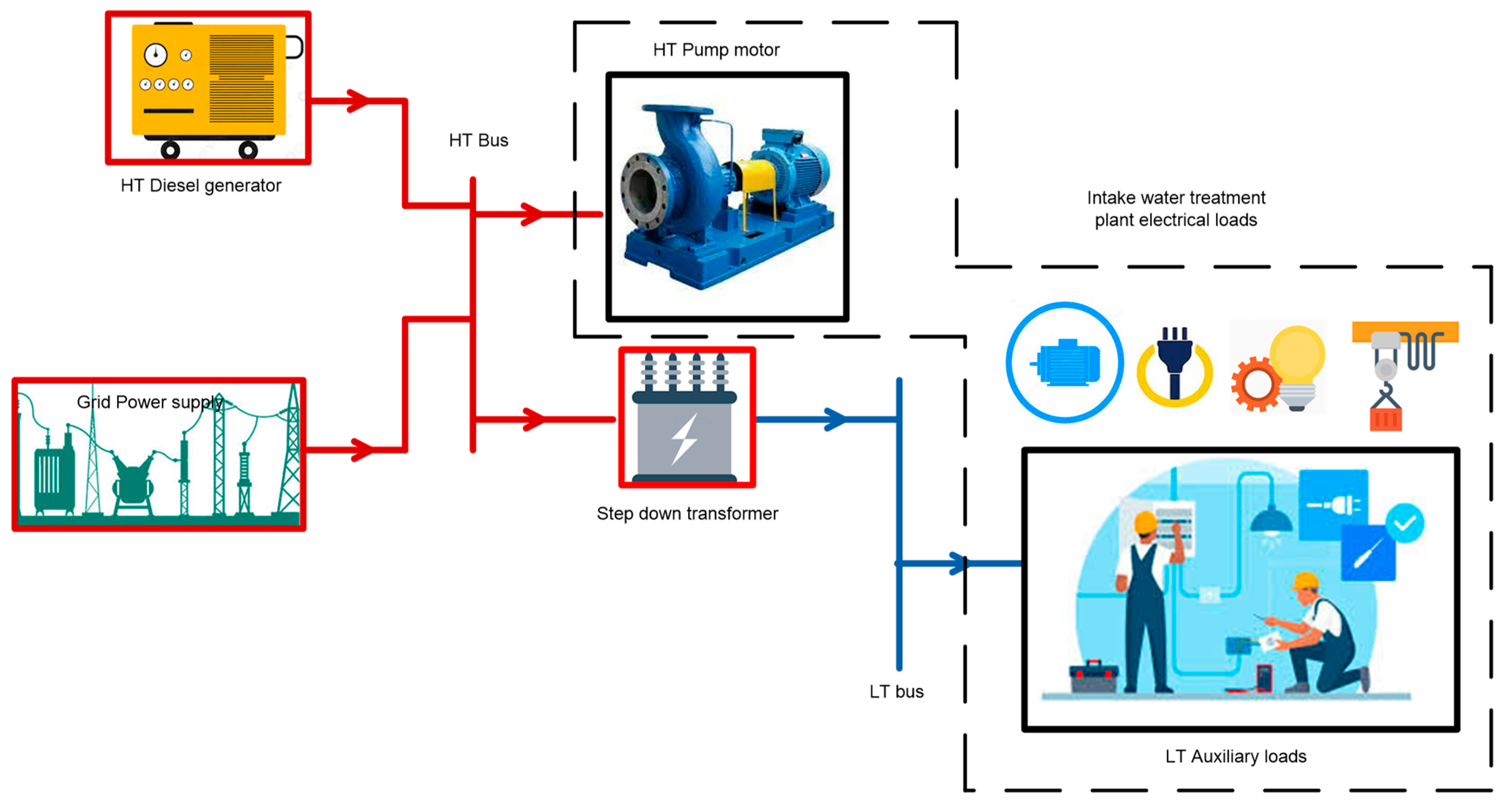
The single line diagram (SLD) of a typical Intake is shown in
Figure 1. Unlike other industries/plant the power requirement for the plant is drawn under high tension (HT) category (also considered as a bulk-consumers) and further stepped down to low tension (LT) for auxiliary loads, as shown in the figure, apart from the main power supply, a HT diesel generator is provided for standby power supply, and the step-down power transformer feeds various auxiliary loads, which could be around 5–20% of the total loads. As public water treatment plant falls under the category of bulk consumers, the running cost as well as the energy cost becomes one of the Government and municipal burden every year. Additionally, operational cost of a diesel generator (DG) set alone contributes huge financial burden, and it is being used by almost all of the water treatment plant so as to meet energy demand during power failure. Not only that, the production of pollutants (particularly CO
2 gas) into the atmosphere harms the environment in many ways. Therefore, Considering the importance and ever-ending demand of reliable public water supply, sustainable treatment as well as sustainable power supply becomes very important so as to improve the treatment as well as reduce the burden of every municipals.
The introduction of distributed energy resources (DER) commonly referred as distributed generation (DG) plays an important role in many power sector applications and could also be applied to the aforesaid problems, especially being faced with a water supply system. Due to the decentralized nature and flexibility, RES becomes more and more popular to overcome the ever-increasing energy demand and is being used in many applications to provide various auxiliary power demand. Moreover, DER offers a wide range of applications and are linked and incorporated with the main grid using control panels and power electronic devices such as converters. In this connection, introduction of microgrid concept in the aforesaid applications can be a game changer for solving various issues and problems encountered in the fields of power sectors.
A microgrid can be defined as an independent energy system (such as university campus, industrial complex, military complex, treatment plants and neighborhood, etc.) consisting of various loads and one or more distributed energy source such as solar panels, wind turbines, battery energy storage system, generators, etc. Microgrid normally operates in synchronous with the grid (grid connected mode) and incase of fault occurrence on the line/grid side, microgrid isolates itself from the main grid and activates the islanded mode of operation, so as to provide uninterrupted power supply to the system. There are different types of control techniques available in grid-connected and in islanded modes, one of the challenges being faced in the microgrid environment is to maintain the system frequency and control the voltage while ensuring the system stability. In grid-connected mode of operation, the basic primary focus is energy management. On the other hand, in an islanded mode of operation, the primary objective becomes control of the frequency as well as the voltage while satisfying the energy demand. Synchronous machine is generally provided to balance supply and demand of power in many system operations. However, if the microgrid system do not contain synchronous machine, inverter alone plays a very important role in providing frequency and voltage control especially in islanded mode of operation [
1,
2]. In short, Active Power (P) as well as Reactive Power (Q) control strategy is being used in the grid-connected mode, and quickly changes its control to voltage frequency control (V/f), when an islanded mode of operation is activated. Additionally, the centralized control architecture is widely used in traditional power networks mainly at the generating station. Whereas, under DER/DG applications, decentralized control architectures are generally applied and used [
3,
4].
Apart from the above case, the microgrid line impedance of different voltage level plays a very important role in considering droop control, generally, in a low voltage (LV) based microgrid system. the lines are normally assumed to be more resistive and thereby considered a relation between (P-V), active power (P) & voltage (V) similarly, (Q-f), reactive power (Q) & frequency (f) relations is considered. Therefore, P-V and Q-f droop combinations and its relations are considered for control of the microgrid voltage and frequency [
5,
6]. Moreover, in a medium voltage (MV) microgrid system, the lines are assumed to be more inductive and hence (P-f), active power (P) & frequency (f) relations is considered similarly, (Q-V), reactive power(Q) & voltage (V) relation is considered. Therefore, improved droop methods, i.e., P-f and Q-V droops and its variants are used for controlling the frequency and voltage [
7,
8,
9]. In line with this, intake of the water treatment plant could be considered as a combination of low voltage and medium voltage loads acting as a separate unit, therefore, resistance as well as the inductance are considered in the line. In this paper the respective P-f and Q-V droop and is considered for controlling the frequency and voltage while considering intake microgrid system [
10,
11].
Apart from the above, some study shows that due to the periodic and fluctuating nature of renewable sources such as wind and solar, the power producing capacity of such DGs is also varying and periodic. Therefore, monitoring and compensation of the reactive power is very important to avoid problems such as voltage change, transient stability and voltage collapse.
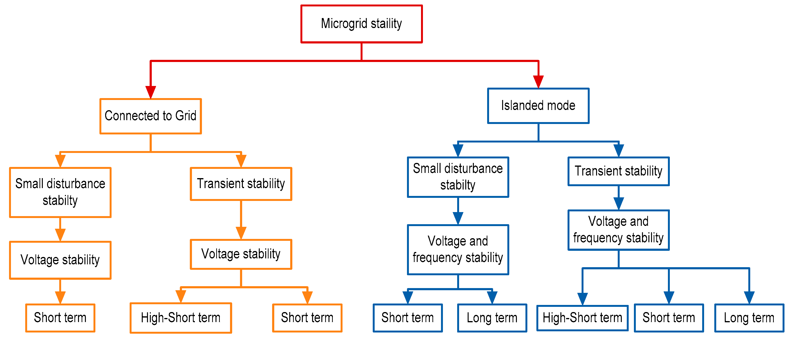
Figure 2 shows different classification of MG stability and, stability in microgrid are categorized into two phenomena such as short-term phenomena (may last up to only a few seconds) and long-term phenomena. Other stability issues more than the short-term phenomena timeframe are categorized as long-term stability. As per requirement, different control methods are available to prevent instability [
12,
13]. In order to solve various problems, including stability issues related to microgrid systems, as mentioned earlier, several efforts have been proposed in various papers. Mostly, microgrid systems are integrated with various renewable energy sources and power electronic devices; improved energy storage elements have been incorporated for compensating energy deviations.
The droop control technique is commonly used to regulate the voltage and frequency for achieving power sharing in the microgrid system and most of the islanded microgrids are operated under droop control techniques. The generalized droop control technique performs well only under grid connected mode, this is due to the fact that generalized droop control relies on the inverter output impedance and impedance of the line between DGs and loads. However, it is difficult to chalk out the accurate line impedance value between the DGs and the corresponding load when the number of DG units are more [
14,
15]. Additionally, droop control requires further development and possesses drawbacks, such as the high droop coefficients, which may cause deviations in voltage and frequency, and this can compromise the grid stability. In addition, due to requirement of complex transformation of the microgrid parameters, implementation of droop control in microgrid is difficult [
16,
17]. Therefore, in order to avoid the aforesaid issues and to remove dependency on line parameters, different intelligent methods such as artificial neural network (ANN), adaptive neuro fuzzy inference system (ANFIS) and Fuzzy logic, etc. are being used in references [
18,
19].
Recent studies proposed various control schemes for power quality improvement in grid connected mode of operation, whereas voltage and frequency regulation in islanded mode of operation. Furthermore, introduction of intelligent based frequency control techniques has been immerged in many scenarios which seems to improve the system response compared to conventional methods. Additionally, application of ANN and fuzzy logic controller (FLC) based frequency regulation in an islanded microgrid is seen in [
20,
21], Many literatures suggested use of a storage elements such as batteries, electric vehicles, fuel cells, capacitors, flywheel storage, etc. to regulate the frequency [
22,
23]. Similarly, this paper has been formulated based on battery storage-based frequency regulation considering intake (public water supply) microgrid system with permanent magnet-based wind turbine and solar photovoltaic system. Additionally, latest intelligent techniques such as Artificial Neural Networks (ANNs), Fuzzy Logic Control (FLC), and Adaptive Neuro Fuzzy Inference (ANFIS) are being used in many papers [
24,
25]. However, application of microgrid system focusing on intake of the water supply system is not yet to be seen in literature. As intake consist mainly motor loads, the focus of the paper is to resolve the problem of frequency deviations in the microgrid system, this paper proposes droop control of a microgrid using Adaptive Neuro Fuzzy Inference System (ANFIS) technique.
The main objectives of this paper are:
To consider intake of water treatment plant as a microgrid system;
To implement DGs on the microgrid system;
To implement droop control and apply the Adaptive Neuro Fuzzy Inference ANFIS technique;
To analyze and compare the result with generalized droop control (GDC) method.
The rest of the paper is organized as follows: Intake microgrid configuration and modelling is discussed in
Section 2, and Control unit Diagram is discussed in
Section 3, in
Section 4 ANFIS-based Droop Control Approach is discussed, follows by Results and Discussion in
Section 5, and finally conclusions are addressed in
Section 6.
2. Intake Microgrid Configuration and Modeling (Topology)
One of the main objectives of a Microgrid system is to maintain equilibrium power flow between demand and supply within the system. In islanded mode of operation, the equilibrium in power flow between supply and demand is generally accomplished by performing load shedding or by adjusting the amount of power generation. Considering Intake microgrid system, various DG units viz. non-renewable (e.g., natural gas, diesel, thermal, nuclear, etc.) or renewable energy sources (e.g., wind, solar, hydro, etc.) can be utilized so as to improves the system performance [
26,
27]. Particularly, wind energy contributes less harmonics in the system compare to other renewable energy sources. However, in standalone system, the system is prone to frequency fluctuations due to its low inertia.
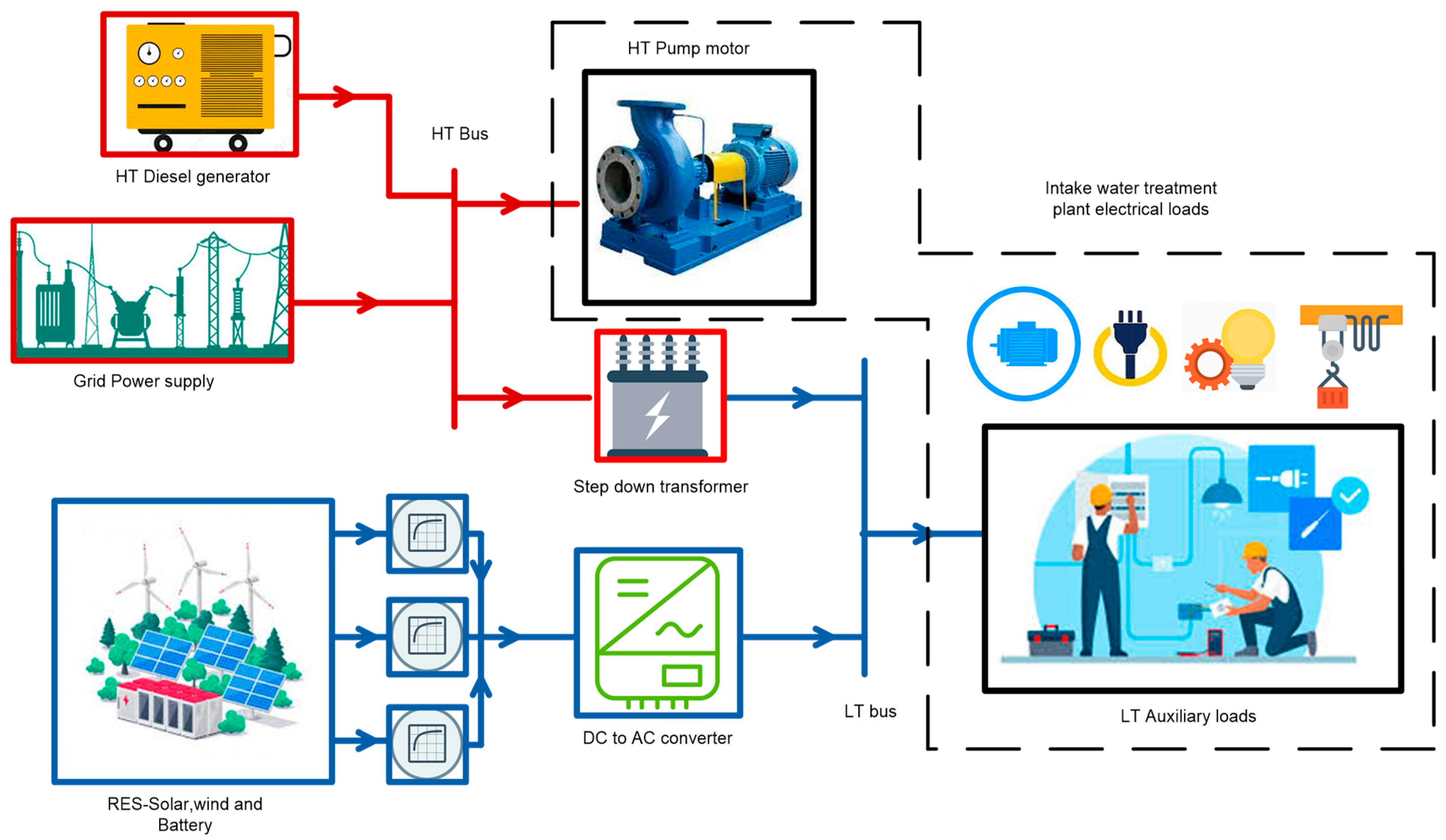
Figure 3 represents the configuration of the proposed intake microgrid system. The intake system has been considered as a microgrid system comprising of HT loads and auxiliary LT loads. In grid connected mode, the power supply from the grid is further stepped down to feed the mentioned various HT and LT loads. The general configuration of the intake microgrid system consist of two voltage levels. First, HT power system, comprises a parallel combination of HT (such as 11 kV) grid and HT Diesel generator, providing power supply to the HT load such as pumps. Second, LT power voltage level has been provided through step down power transformer for feeding various LT loads such as compound lighting, quarters and office, etc. In the LT side of the microgrid, implementation of various DGs such as PV system, battery energy storage system (BESS) and permanent magnet-based wind turbine generator such as interior (or buried) permanent magnet machines (IPM) are also provided as a backup power source, as shown in the figure. These DGs are interlinked with a boost converter (DC to DC) through voltage source converter. Similarly, the BESS is coupled to the converter (DC side) using bidirectional DC to DC converter. From the PV array, the boost converter (DC to DC) extracts the maximum available power to compensate for the load using maximum power point tracking (MPPT). On the other hand, the bidirectional converter provides charging and discharging of the battery. Additionally, BESS keeps the dc-link voltage of the converter constant while providing required power supply irrespective of change in PV power output. IPM based wind turbine generator is linked to the DC side of the converter via boost converter (DC to DC). The converters are further connected to the DC-AC converter through DC link. The output of the converter is fed to the LT bus through LC filter and a coupling inductor. Various LT loads are connected at LT bus or point of common coupling (PCC).
As the proposed microgrid system contains HT and LT combinations, Diesel engine generator alone is sufficient enough for the whole power back up, i.e., for HT load as well as LT load. However, due to high operational cost and maintenance cost, Diesel generator has been considered only for HT load. Therefore, in this paper various DGs are proposed for LT side only and the control strategy of the system has been considered only for the LT side of the microgrid system.
Table 1 and
Table 2 show details of the various loads and DGs connected to the intake microgrid system.
As the microgrid system operates in grid connected mode and islanded mode, the proposed intake microgrid system has been designed and considered to operate in both modes of operation.
Table 3 shows the operation of microgrid in grid connected and islanded mode of operation. In grid connected mode, various load such as Motor load, pumps and Light load, etc. are operated as per system requirement so as to pump maximum water from the river. The main power supply from the grid supplies power to the system in full, and BESS harvested the energy generated from the PV and Wind energy sources while providing the required power supply to the system. Additionally, as per requirement extra energy generated from the RES can be used to compensate power cost from the grid. In islanded mode of operation, the intake system gets isolated from the main grid and governs its own power flow, i.e., Diesel generator and RESs feeds the system in full while isolated from the main grid supply. Additionally, various converter plays a very important role in control and energy conversion. Management of power flow and optimization of stability in the system has been achieved by performing droop control in both the operating conditions.
2.1. Modeling and Control of PV with Battery System
Several renewable energy generation technologies have been utilized and practiced nowadays, out of these, solar photo voltaic system is one of the most important renewable energy generation sources and is being commonly used in many countries. The Solar PV system has various advantages such as pollution free, less maintenance cost and no fuel costs, etc., it is easy to install, and it plays a very important role in reduction of greenhouse gases and contributes positive impact in many environmental concerns. Therefore, it is ideal and a very good alternate source, when it comes to the topic of replacement of fossil fuel energy generations [
28,
29].
Under grid connected mode of operation, the main concern regarding control is power sharing between load and source, however in islanded or stand-alone mode of operation, the power sharing as well as voltage and frequency control becomes very important, in order to achieve this proper design and calculation of the microgrid system is required. Additionally, the dynamics of the loads and the power sources must be properly considered [
30,
31]. In islanded mode of operation, the PV system may not always follow the maximum power point in order to balance the sources and loads. Therefore, in order to satisfy the load requirements viz. linear and nonlinear loads, provision of additional energy source like a battery energy storage system (BESS) is required to optimize the operation of Solar PV system. In this paper, combination of PV system and battery energy sources is considered to obtain maximum power and control of DC link voltage is achieved by implementing electronic converters.
Figure 4 shows the schematic diagram of the Solar PV with BESS system. Here, solar PV and BESS are connected to DC link capacitor and further connects to the three-phase inverter (DC-AC). A DC to DC boost converter is used to boost the solar output voltage magnitude as per system requirement, and hence, it is basically used to drive the solar PV output power. Similarly, A bi-directional DC-to-DC converter is connected to the battery energy storage system, the converter alters the course of switching by charging or discharging the battery while achieving the DC link voltage. The three-phase inverter is used to convert DC voltage to AC voltage and controls the load voltage magnitude. In this paper, various loads analogous to intake LT loads are considered and implemented in MATLAB Simulink environment.
2.1.1. Solar Photo Voltaic (SPV) System
The designed parameters of the solar PV system are shown in
Table 4, the solar PV system equation of the nonlinear model relating to the PV current and the terminal voltage is defined in the following equations
where
Irs and
ϴ represents the reverse saturation current and the temperature of
p −
n junction.
A is the ideality factor
Iscr is the short-circuit current of a single PV cell and
S is solar irradiation level,
ns and
np are the series and parallel number of PV cells in a string,
q (=1.602 × 10
−19 C) and
k (=1.38 × 10
−23 J/K) are the unit electric charge and Boltzmann’s constant respectively, also,
ϴr is the cell temperature reference and
kϴ is the temperature coefficient [
32,
33].
Similarly, equations for Boost Converter and the PV System can be defined as follows
Therefore, from the above equations (
D1 = 1 −
S1)
2.1.2. Battery Energy Storage System (BESS)
Battery have been widely used in many applications nowadays, and the commonly used grid connected types of the battery are lead-acid batteries (PbAc), vanadium redox batteries (VRB), lithium-ion batteries (LIB), and sodium-sulfur batteries (NaS). However, one of the main issues being tackled is degradation of the battery efficiency. There are several factors causing degradation of the battery such as battery age, current, discharge/charge voltage, temperature, and the level of discharging/charging [
34,
35]. Additionally, the factors effecting the life of the battery can be broadly categorized as battery storage period, i.e., environmental factors, and during usage, i.e., cycling conditions. In this paper the battery energy storage system has been considered and it plays a very important role in achieving power sharing during islanded mode of operations.
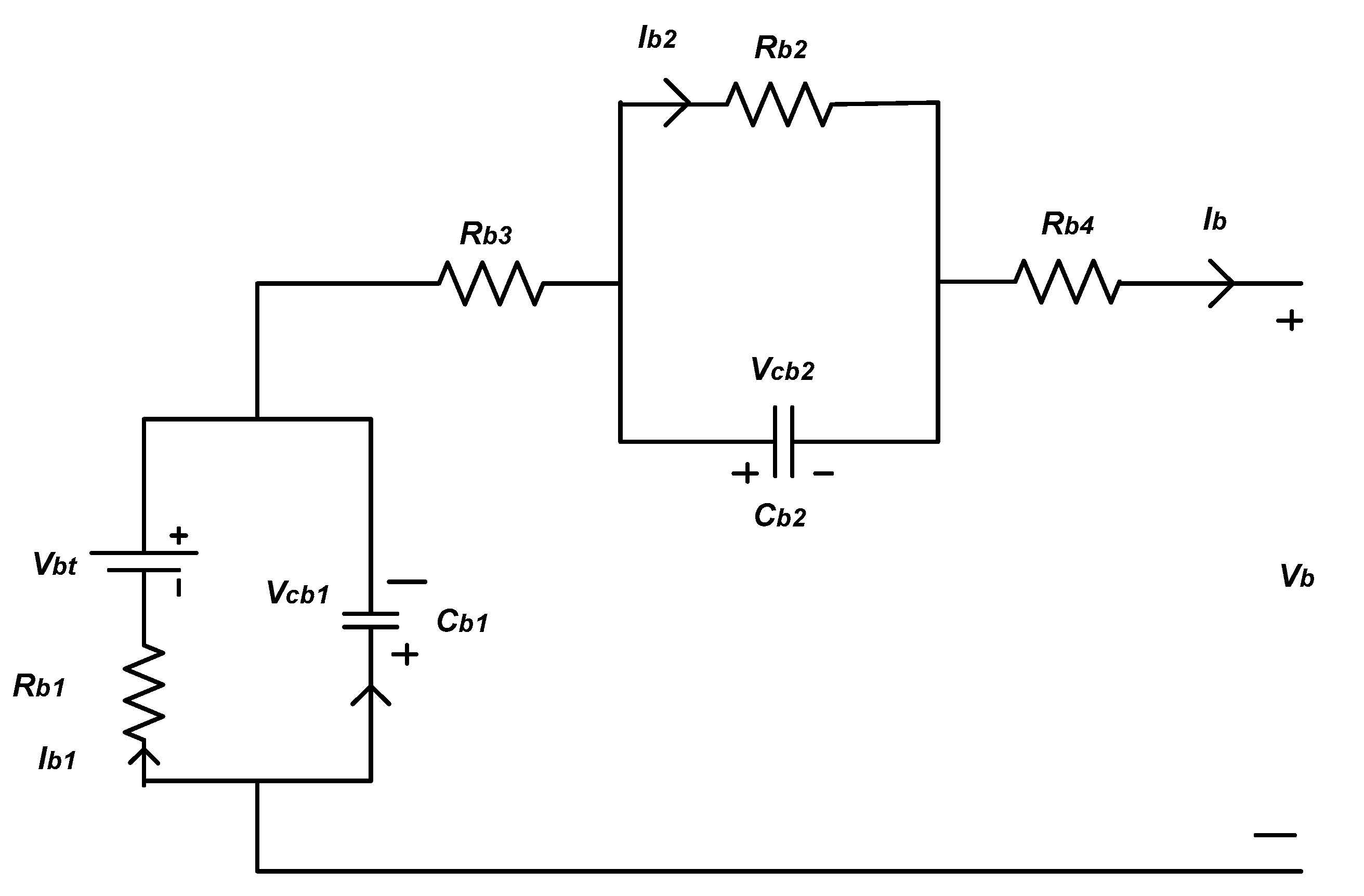
As shown in
Figure 4. The Battery energy storage system is connected with the solar PV system through a bidirectional converter (DC to DC converter), the bidirectional DC to DC converter is further connected to the DC-link and the battery equivalent circuit is shown in
Figure 5. Equations relating to the characteristics of the battery are defined in this section. Additionally, the parameters of the battery are given in
Table 5.
Where
Vb and
Vbt represents the terminal Voltage and the internal source voltage (V),
Rb1 represents the internal source resistance (Ω) and
Cb1 represents internal capacitance (F),
Vcb1 represents the Voltage (V) across
Cb1. Where
Ib1 represents internal battery current (A),
Rb2 represents poarization resistance (Ω) and
Rb3 represents ohmic resistance (Ω), which are connected to the charging and discharging properties of the battery, i.e., transient dynamics respectively.
Cb2 represnts the polarization capacitance (F) and
Vcb2 represents Voltage (V) across
Cb2. Additionally,
Ib represents the battery output Current (I). Equations related to the dynamic model of the battery can be expressed in the following equations [
36,
37].
The bidirectional boost converter for the battery is given by
When
S2 is on (
S2 = 1,
S3 = 0)
When
S2 is off (
S2 = 0,
S3 = 1)
After combination of the two modes of operation (
S3 = 1 −
S2)
From the above the DC link voltage equation can be given as
2.2. Modelling and Control of WIND Turbine Generator
Nowadays, the use and development of renewable energy sources such as geothermal, Solar and wind has become very popular and has been introduced worldwide. Like other sources, energy generation from the wind has been remarkably popularized and have been improved and developed since the last decade. Mostly wind turbines are either synchronous generator based or doubly fed induction generator (variable speed) type. Additionally, Permanent magnet (PM) based wind turbine generators are commonly used in wind turbine applications due to the nature of excitation free operations; Also, it offers high efficiency and reliability compared to the other generators [
38,
39,
40]. Permanent magnet synchronous machines are divided into two; one, permanent magnet (surface mounted) machines (SPM) and two, interior (or buried) permanent magnet machines (IPM). In SPM, the magnets are properly installed on the rotor surface. Thus, the saliency effect becomes negligible. However, in the IPM, saliency effect occurs due to non-uniform equivalent air gap. Therefore, in comparison, the IPM machine has advantages such as solid and robust structure, physically protected and contained magnets. Additionally, the generated magnetic torque and generated reluctance produces higher efficiency and allows the machine to operate in a wider range of speed. Due to this, the IPM model is considered in this paper and the AC-DC-AC converter is used between the main grid and the wind turbine [
41,
42].
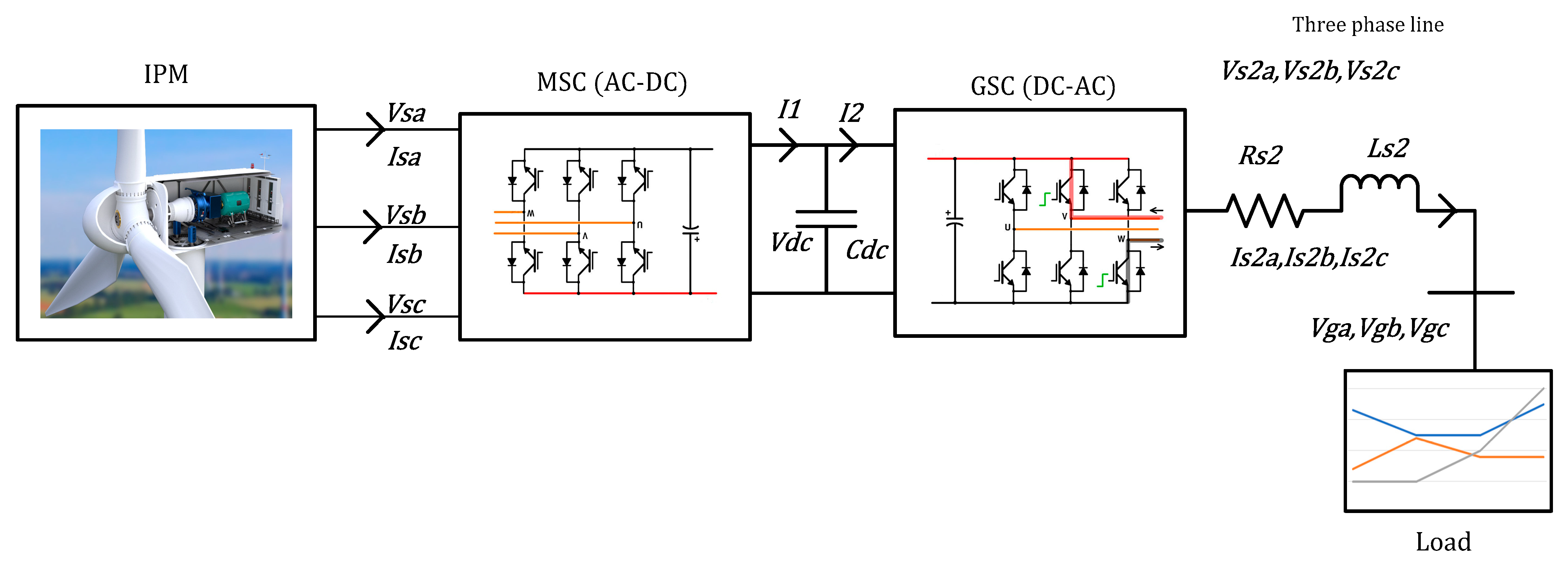
The basic diagram of the IPM wind turbine system is shown in
Figure 6. The wind turbine basically consists of blades, generator and converters. For design purpose a three-blade horizontally mount wind turbine is considered. Similar to the other wind turbine system, an IPM utilizes the mechanical energy of the gear system which is converted from the shaft of the turbine blades, the wind turbine converts further the mechanical energy into electrical energy, which is connected further to the electrical system through machine side converter (MSC, i.e., AC to DC converter) and Grid side converter (GSC, i.e., DC to AC converter). As shown in the figure, the GSC and the MSC are connected with the IPM. The MSC controls the speed of the wind turbine rotor and tracks maximum power point of the available power and minimizes the power losses. On the other hand, the grid side converter (GSC) maintains the DC link voltage and controls the flow of the reactive power to the grid as per system requirement [
43,
44].
The main focus relating to control of the wind turbine is to attain maximum available power from the wind while maintaining constant voltage at the DC link, one of the other important factors is assurance of unity power factor. The power and torque can be calculated as follows
where
ρ is the air density,
is the wind speed,
A (=
πR2) is area swept by the rotor,
R is the turbine rotor radius,
λ is tip speed ratio,
is the angular speed of the wind turbine shaft,
β is the rotor blade pitch angle, and
is the power coefficient [
45,
46]. The parameters of the wind turbine are shown in
Table 6.
4. ANFIS-Based Droop Control Approach
ANFIS Architecture and Controller
ANFIS falls under the category of an Artificial Intelligence (AI) system and it is a hybrid combination of Neural Networks (NN) and Fuzzy Logic (FL) technique. It is generally used in various fields for solving complex and nonlinear systems. The ANFIS provides an adaptive modelling method for learning information from the set of input data. The membership functions (MFs) and Fuzzy rules are obtained by training the system using selected data sets, during the training process the parameters of the MFs can be adjusted accordingly. Additionally, hybrid or back propagation learning methods are used so as to determine the parameters of the adaptive system.
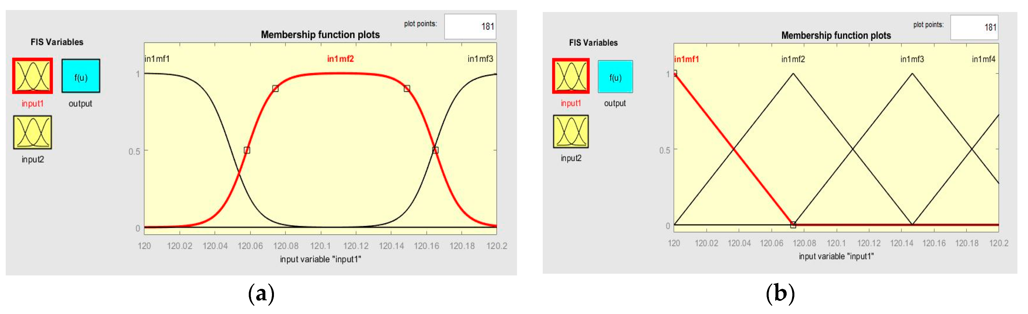
In this paper, the trained ANFIS has two input data, i.e., active power (P) and reactive power (Q) where the corresponding output are frequency (f) and Voltage (V). different learning algorithm, i.e., hybrid algorithm for each input is used in order to determine the parameters, one of the advantages of using ANFIS is non requirement of previously obtained information about the MFs rules if the ANN are properly tuned. Additionally, the ANFIS can selects the MFs parameters automatically based on requirement. The parameters of the MFs are set and determined by using Product of two sigmoidal membership function (psigmf) and the Triangular membership function (trimf) method.
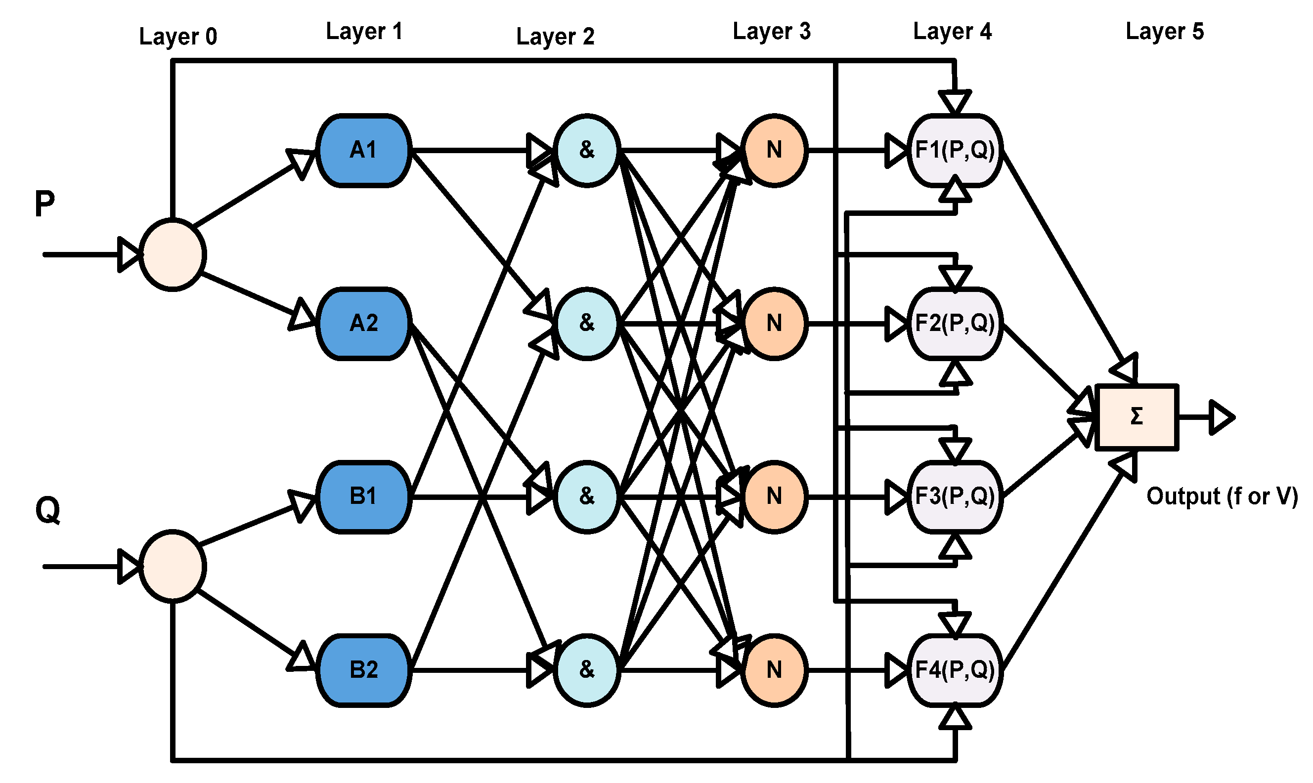
The typical ANFIS structure shown in
Figure 15 has Multi Input Single Output (MISO) structure and the structure contains five layers, where P and Q are the two active and reactive power inputs. Additionally, A1 and A2 represents the membership functions of input P, whereas B1 and B2 represents the membership functions of input Q. The First layer represents the membership function of each individual inputs. Additionally, AND operation is performed in the second layer for both the MFs of input one and input two, the corresponding rules for the input could be formed as follows; [
53,
54].
Rule no 1: If P is A1 and Q is B1, then f1 = p1P + q1Q + r1,
Rule no 2: If P is A2 and Q is B2, then f2 = p2P + q2Q + r2.
From the above rules, p1, q1, r1 and p2, q2, r2 represents the parameters of each of the output functions. Each node of these output is referred as firing strength of a rule. The corresponding layers of the ANFIS are explained in the followings
Layer 1: Every node in the first layer represents a square node containing a node functions, the fuzzy sets are obtained by applying the input variables, which are in proportional to the input variables. Each node representing as an I in the layers have a function representing the membership value of each input, the corresponding node output are described as follows
where
Q and
P represents the input of node
i,
Bi (or
Ai) represents the linguistic label (could be small, large, etc.). Additionally, it can be stated that
O1,
i is the MF of
Ai. and it specifies the degree to which it satisfies the quantifier
Ai. Normally,
μAi is selected in a bell-shaped form containing a limit set of 1 as maximum and 0 as minimum correspondingly,
μAi(
P) can be given as follows [
55,
56]
where
,
,
are known as the premise parameters and are called parameter set, as the values of these parameters change, they exhibit several forms of membership functions on
Ai or linguistic label.
Layer 2: Every node in the second layer is a multiplication of the output of first layer and sends the product out. It can be represented as,
Each node output represents the firing strength of a rule, i.e., Wi. The signals from the incoming are ith line with the precursor (if) of the rule.
Layer 3: In the third layer, every node represents a circle node written as
N. the activity of each and every rule is considered. The number of fuzzy rules and the number of layers is equal. This layer output is considered as a regularized form of the previous layer. The
ith node computes the ratio of the
ith rule’s firing strength against all rule’s firing strengths, as shown below [
57].
Layer 4: In fourth layer, the products are the fractional output values, i.e., from layer 0 and layer 3, the output node i are Takagi-Sugeno type represented as follows
Whereas, is the output of the fourth layer, , are the parameter set, denoted as consequent parameters
Layer 5: The final ANFIS output is obtained in the fifth layer. The output is nothing but the summation of the incoming signals from the layer four as shown below.
The fifth layer is nothing but the defuzzification layer, this fifth layer computes the result of the previous layers and the ANFIS output, the node function contains almost no constraints except piecewise differentiability in an adaptive network. Additionally, the one constraint in the adaptive network configuration is that it should be a feedforward type. Due to these constraints, applications are instantaneous and vast in many areas. Implementation of ANFIS and Validation
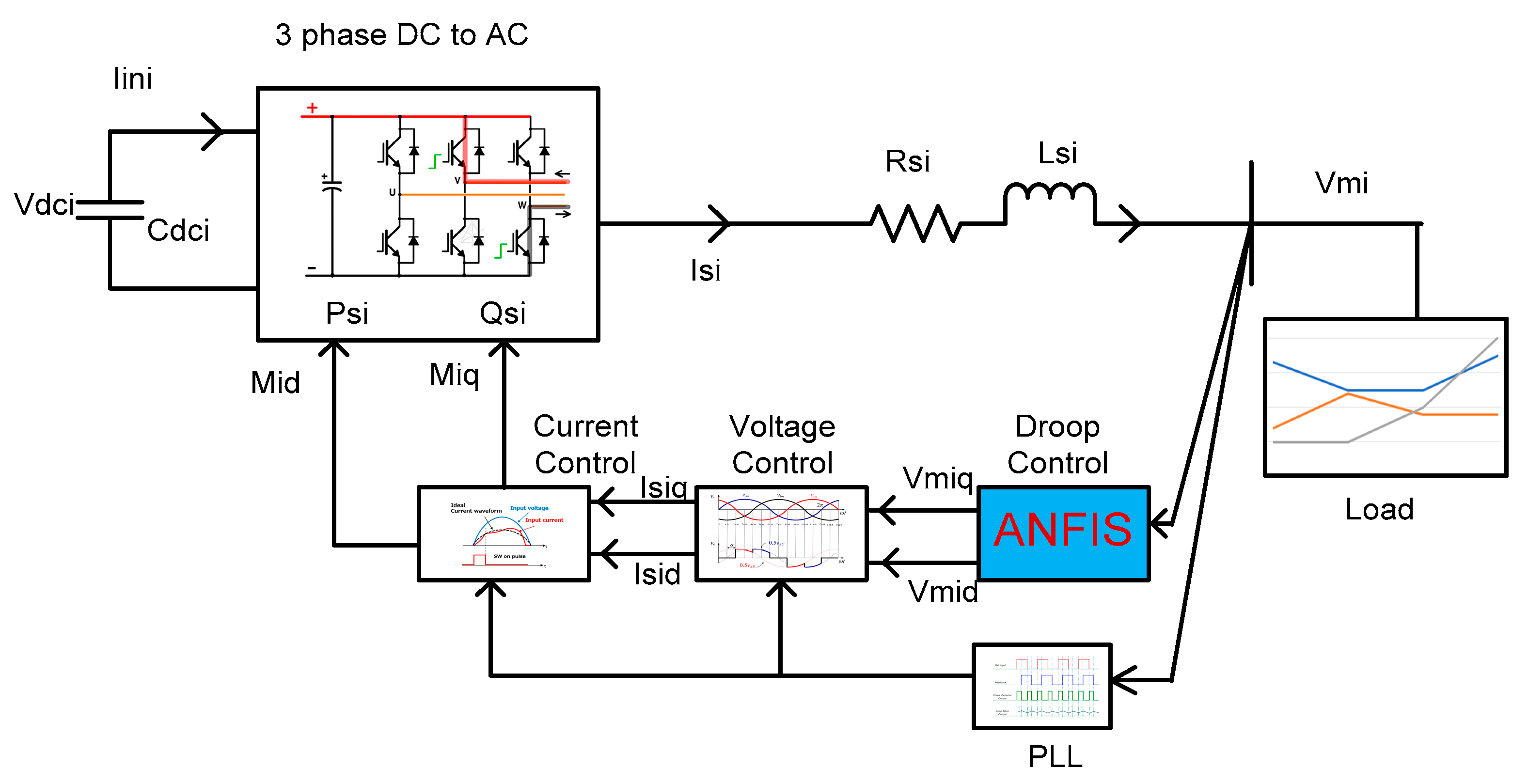
In order to implement the ANFIS-based controller, the generalized droop control structure, shown in the
Figure 7 can be remodelled by ANFIS as shown in
Figure 16. Therefore, after ensuring the validity of the model, the proposed ANFIS-based controller could be used for droop control as shown in the figure.
After implementation of the ANFIS-based droop control model, the input and output data set are used for training the ANFIS, the droop control unit consists two input data, i.e., active and reactive power and two output data, i.e., frequency and voltage amplitude, separately. In order to smoothly carry out the operations, two ANFIS blocks are individually applied for controlling the voltage and frequency outputs. Additionally, ANFIS operates on multi-input-single-output (MISO) signals only. The input and output data set are generated and stored in the system, and the corresponding ANFIS models are generated and trained. After continuous training of the ANFIS, the error tolerance values are evaluated and minimal training RMSE result shows that ANFIS has been trained successfully. Therefore, after successful training, the conventional controllers are now been replaced with the trained ANFIS controllers, the active and reactive loads are then changed by switching various loads and the system output frequency and voltage are compared to the conventional droop results. ANFIS training data for the frequency control as well as voltage control are shown in the
Table 7 and
Table 8 below.
Here, the Membership Functions data for frequency and Voltage are carefully chosen, such as input number of Membership Functions (MFs), Input MFs type are carefully chosen and compared with other combination options such as Triangular membership function (trimf), trapezoidal membership function (trapmf), Generalized bell-shaped membership function (gbellmf), Gaussian membership function (gaussmf), Gaussian combination membership function (gauss2mf), pi-shaped membership function (pimf), difference between two sigmoidal membership function (dsigmf). Selection of MFs plays a very important in choosing the optimal sets of output, each MFs type offers different results as per training procedures. After completion of training different combination of data sets. The ANFIS info such as Number of nodes, Number of linear parameters, Number of nonlinear parameters, Total number of parameters, Number of training data pairs, Number of checking data pairs, and Number of fuzzy rules are compared to see the optimal results and most important of all the lowest Minimal training RMSE is chosen as it shows best results where the selection of zero error tolerance is chosen in training the data sets. After finalization of the required data the optimal ANFIS train data for Frequency and Voltage are selected as shown in the below table. Similarly, the corresponding output P-f and Q-V sets of trained data are shown in
Table 9 below.
6. Conclusions
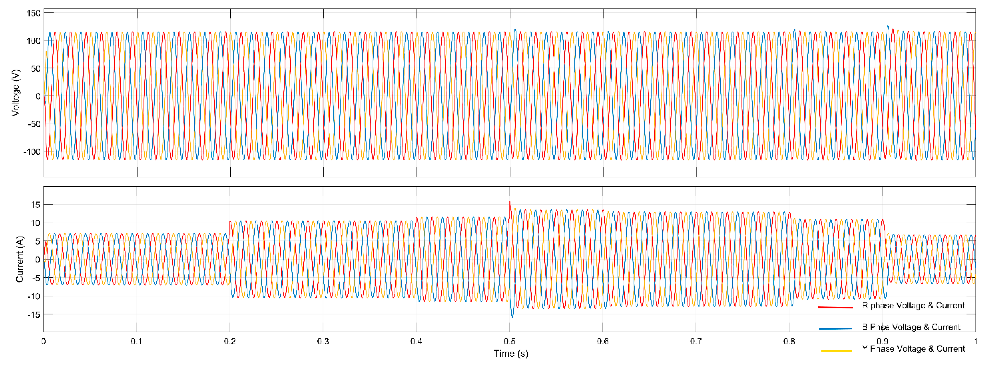
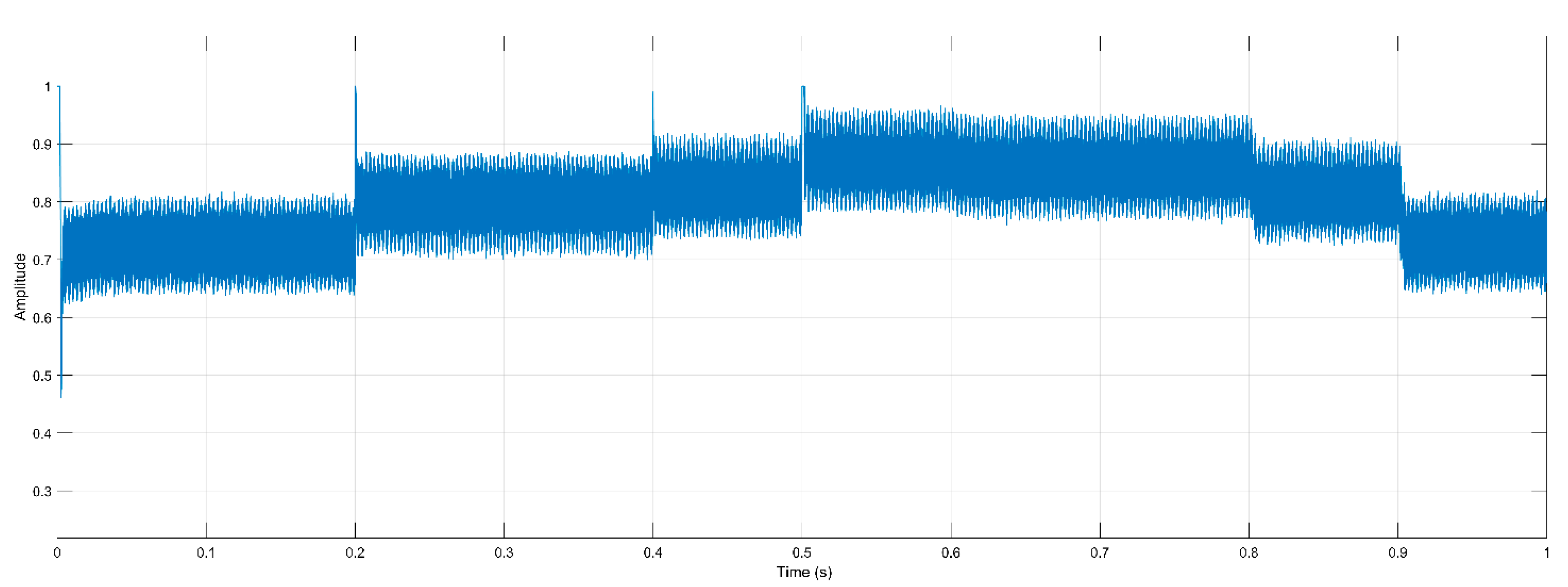
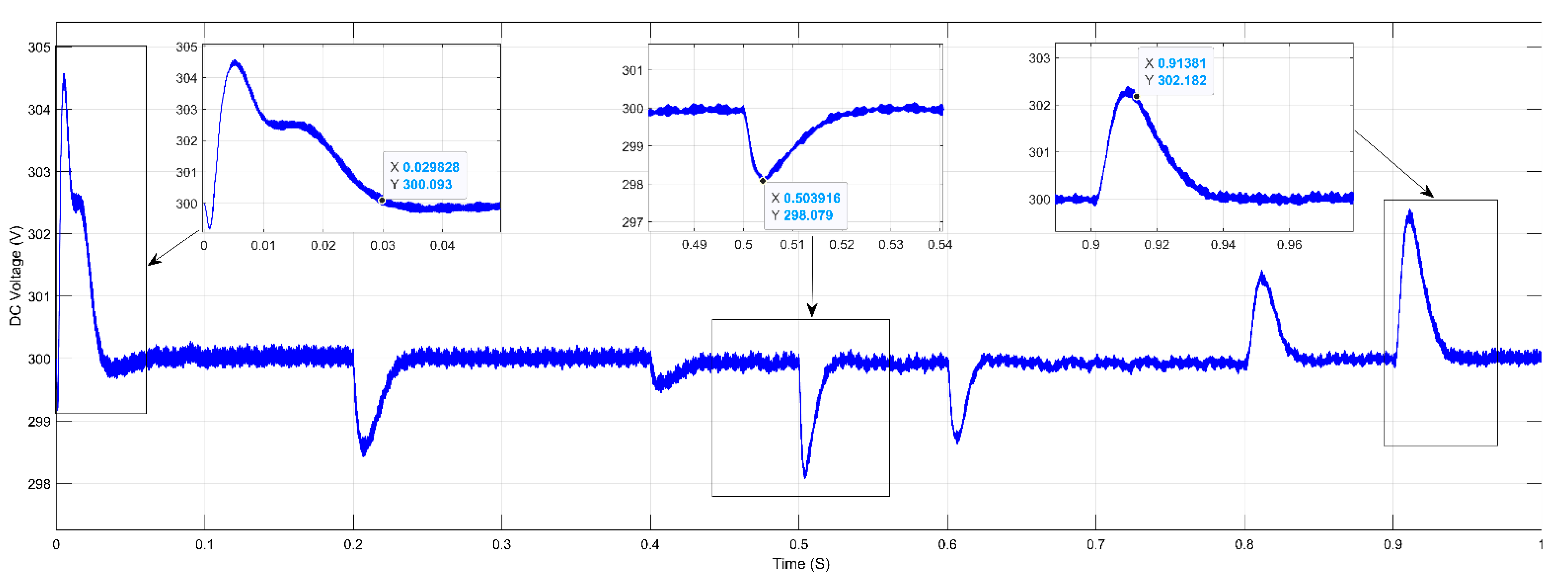
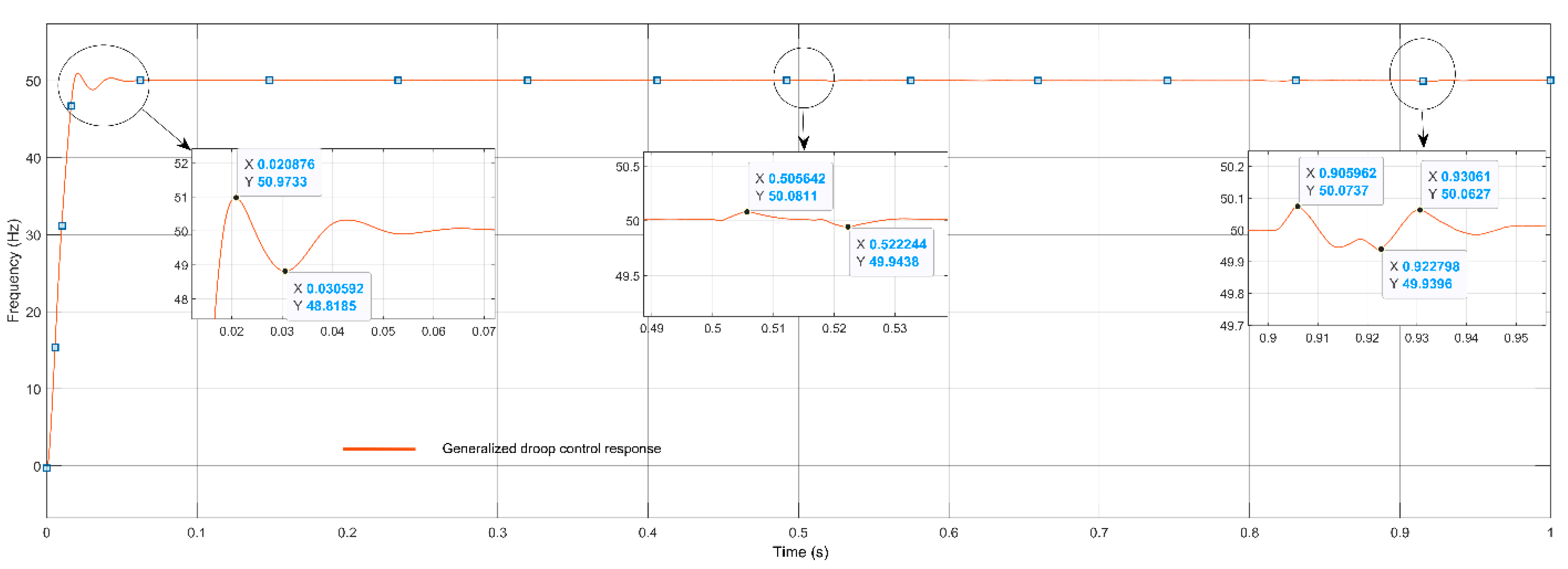
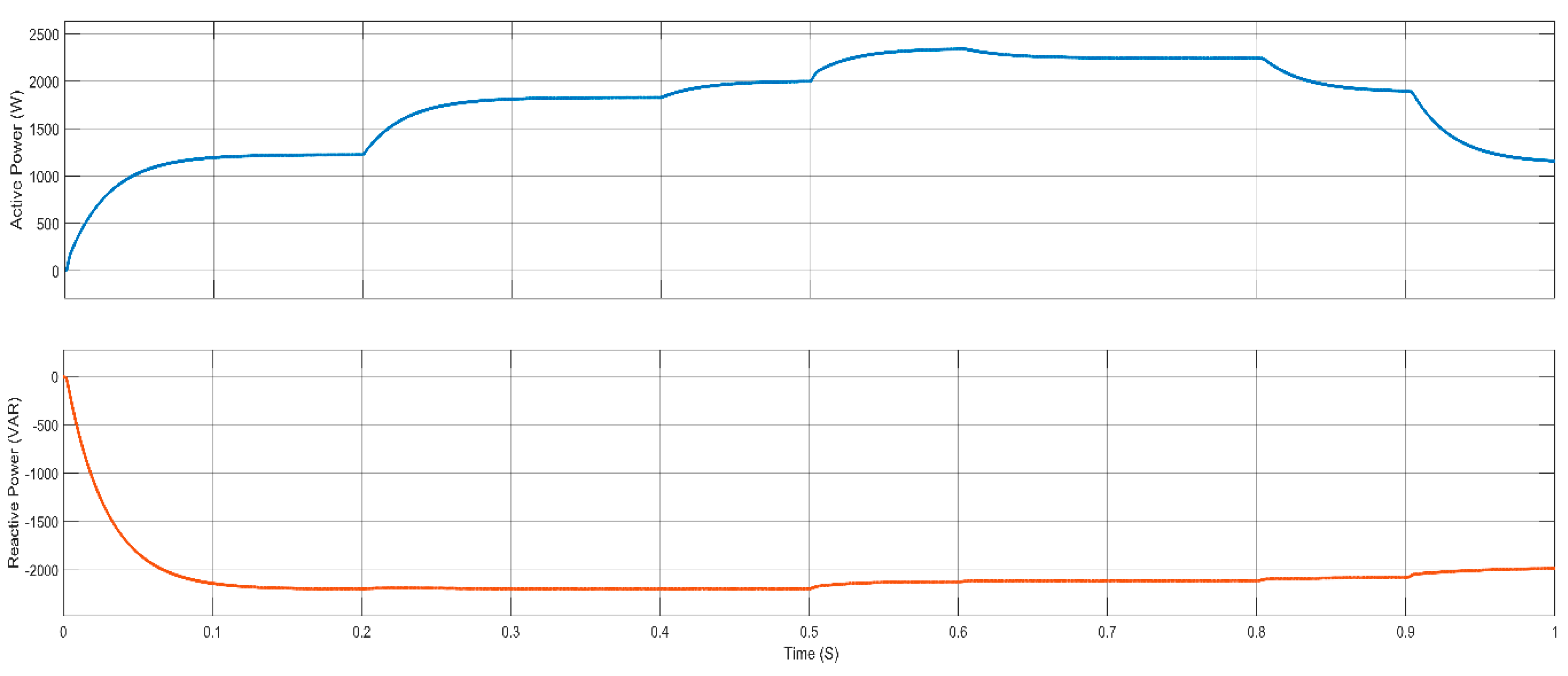
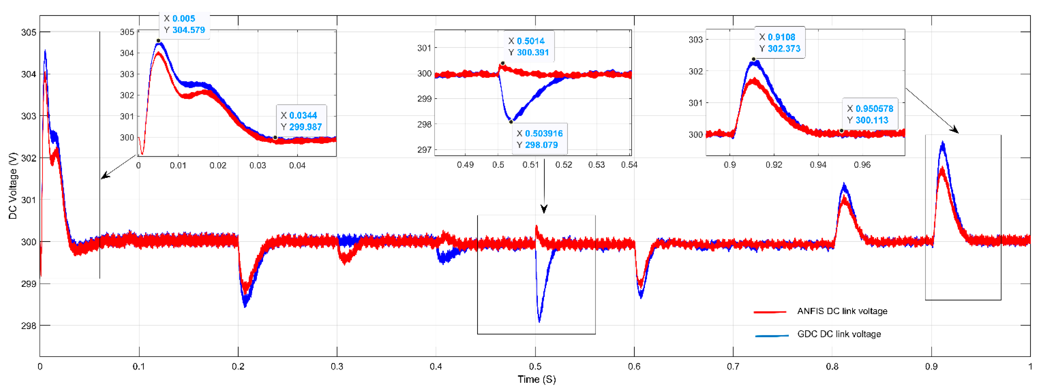
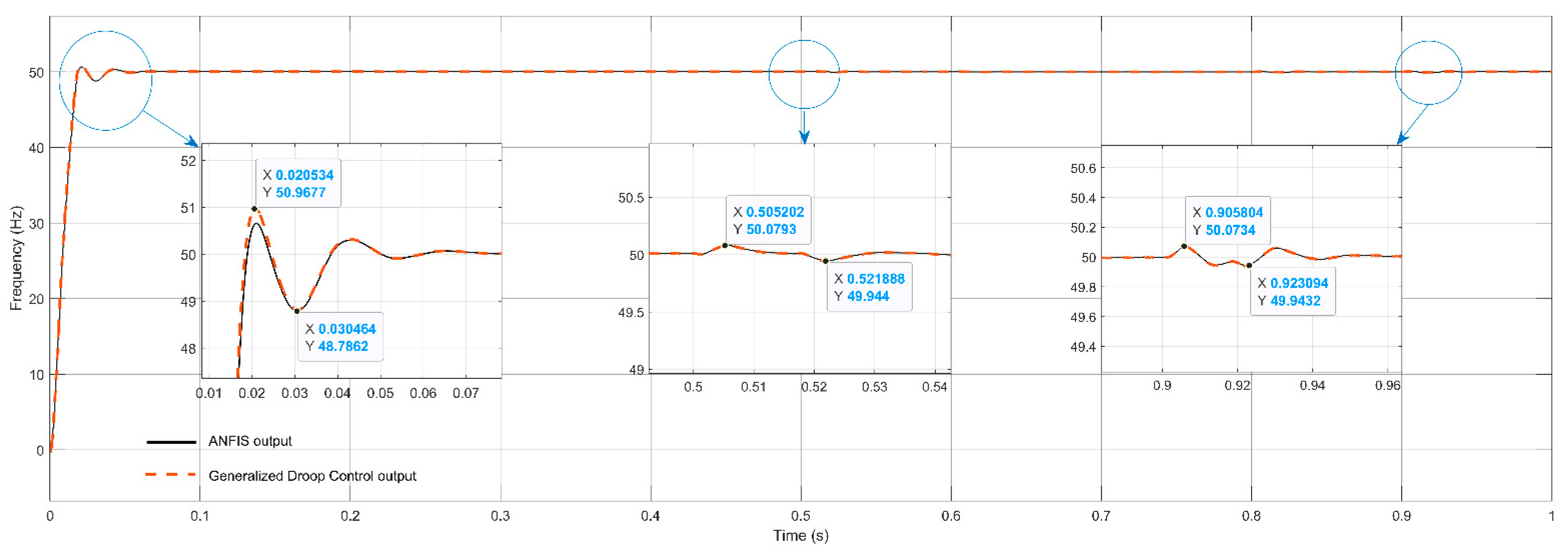
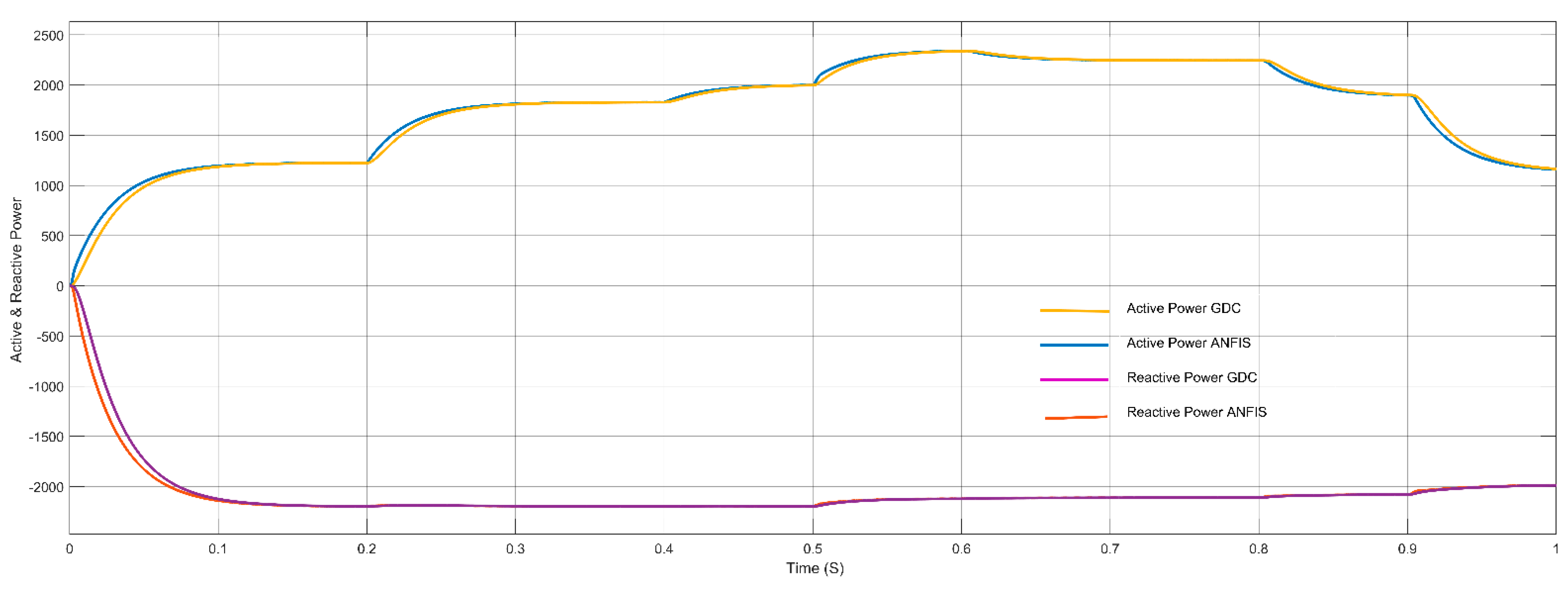
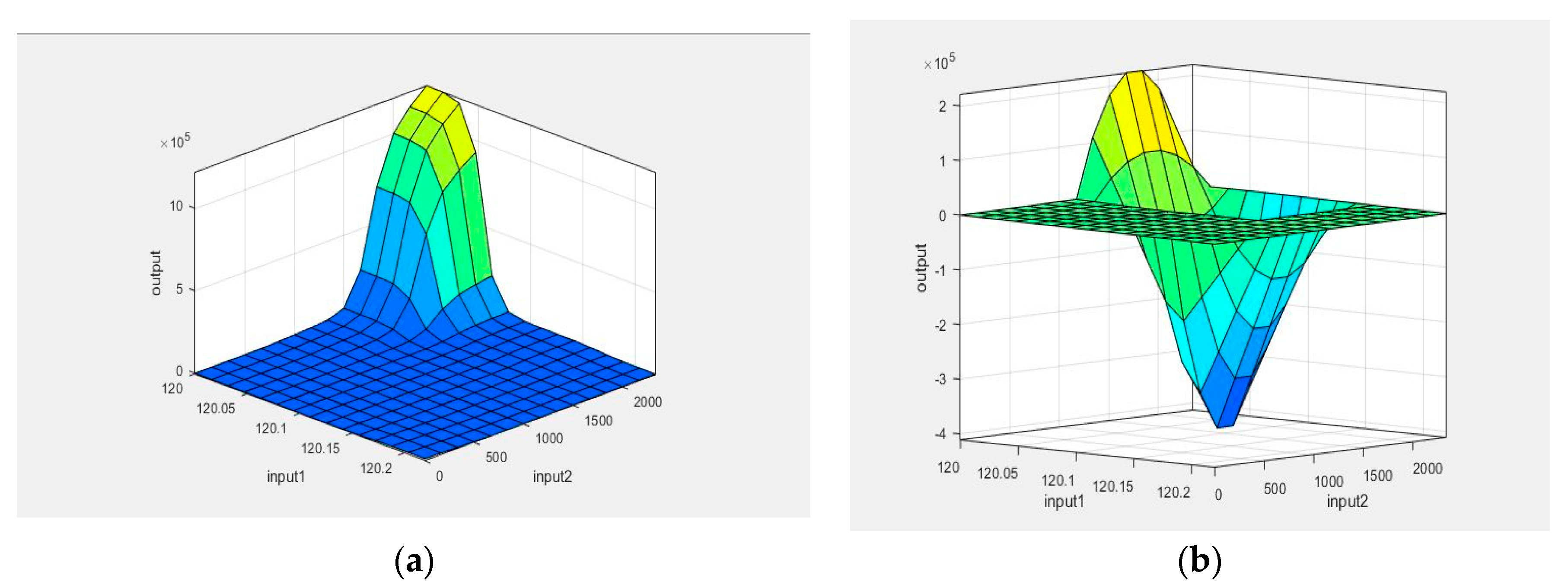
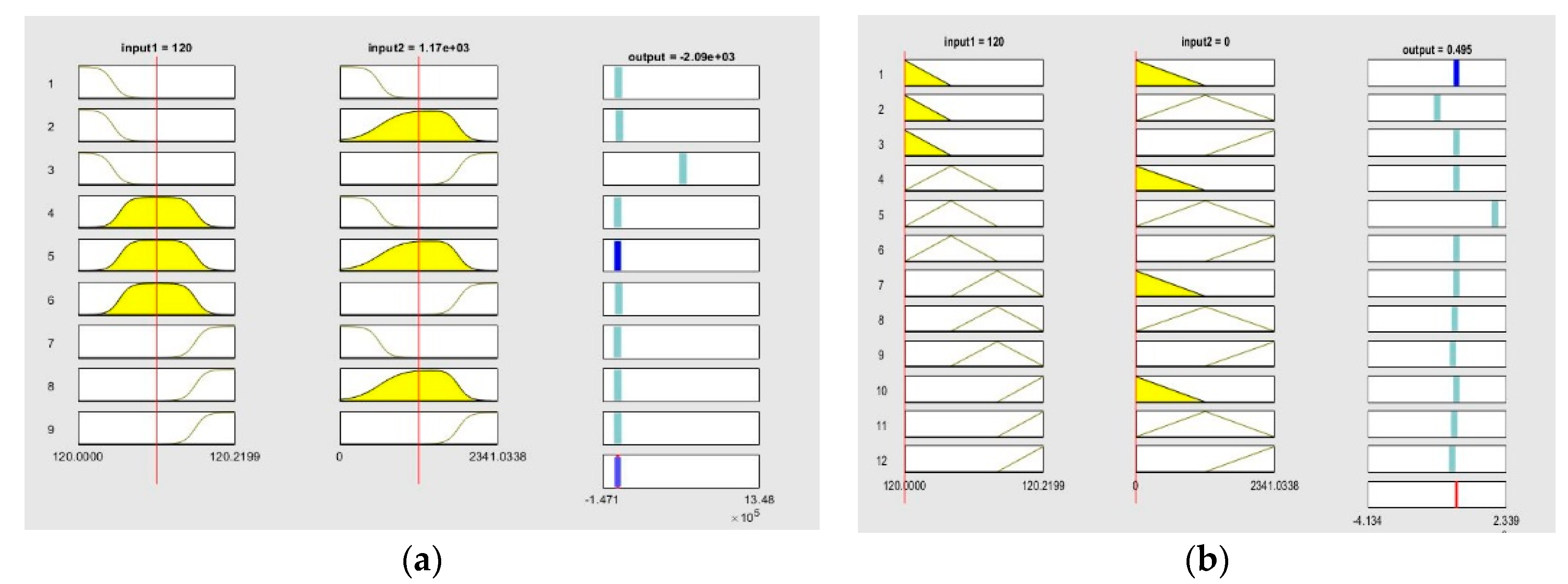
In this paper ANFIS-based Droop control technique considering intake microgrid system was analyzed under different loading conditions, which is considered analogous to different loadings of intake system. Similarly, in order to compare and analyze the results, the conventional droop control technique using generalized droop control (GDC) technique has also been considered. Simulation results were shown for different loading conditions. ANFIS has been successfully trained for considering both the cases of P-f and Q-V droop separately. Moreover, the controller block for both the P-f and Q-V droop are replaced with trained ANFIS controllers, and simulations were drawn for different loading conditions. GDC seems to show acceptable results under grid connected and islanded mode of operations, the corresponding graphs such as load vs. source power, V&I at PCC, Modulation index, DC link voltage, frequency, and active and reactive power were observed, and the system seems to show good results; however, transient behavior during switching may disturb the system and may even cause unwanted issues. In grid-connected mode, power sharing of active and reactive powers between source and load plays a very important role, whereas, in islanded mode, control of the system frequency and voltage becomes the main challenge and ANFIS-based droop control technique was considered for solving this issue. As the intake contains both the HT load and LT loads, only the LT side of the load has been considered in the simulation. The designed system operates in grid connected mode for 0.5 s and islanded mode for 1 s. As various load changes the battery system compensates the overall power sharing between source and load. The trained ANFIS data such as surface plot, fuzzy rules, membership function plot and RMSE value of both the P-f and Q-V droop shows successful training of the ANFIS and the corresponding application was made by replacing both the controller units of P-f and Q-V.
Considering the stability of the proposed microgrid system, frequency plays a very important role in analysis of the system performance. In fact, in the droop control technique, the frequency of the system is highly depending on the active power balance between load and source. In the proposed intake microgrid system, batteries play a very important role, and it injects and absorbs the real power during frequency imbalance. Additionally, the system voltage is highly depending on the reactive power balance between the source and load. The proposed ANFIS-based droop controller seems to show good results in regulating the frequency, as well as voltage of an intake microgrid system. The reliability has been tested by comparing the performance of the GDC, and it has been tested in different loading conditions. The comparison of the simulation results shows satisfactory performance of the ANFIS system.
As far as the consideration of water treatment plant-based intake microgrid is concerned, the same concept could be useful for solving various issues being faced in various water treatment plants, such as huge operational costs, power-related issues, frequent maintenance, etc. By adapting the same technique, ANFIS-based droop control could also be used in several treatment plants similar to waste water treatment such as sewage treatment, etc.


